EP4145802A1 - Dienstgüterahmenverbesserungen für 5g-dienst - Google Patents
Dienstgüterahmenverbesserungen für 5g-dienst Download PDFInfo
- Publication number
- EP4145802A1 EP4145802A1 EP22190260.4A EP22190260A EP4145802A1 EP 4145802 A1 EP4145802 A1 EP 4145802A1 EP 22190260 A EP22190260 A EP 22190260A EP 4145802 A1 EP4145802 A1 EP 4145802A1
- Authority
- EP
- European Patent Office
- Prior art keywords
- qos flow
- packet
- sdf
- wireless device
- data
- Prior art date
- Legal status (The legal status is an assumption and is not a legal conclusion. Google has not performed a legal analysis and makes no representation as to the accuracy of the status listed.)
- Granted
Links
Images



Classifications
-
- H—ELECTRICITY
- H04—ELECTRIC COMMUNICATION TECHNIQUE
- H04W—WIRELESS COMMUNICATION NETWORKS
- H04W28/00—Network traffic management; Network resource management
- H04W28/02—Traffic management, e.g. flow control or congestion control
-
- H—ELECTRICITY
- H04—ELECTRIC COMMUNICATION TECHNIQUE
- H04W—WIRELESS COMMUNICATION NETWORKS
- H04W28/00—Network traffic management; Network resource management
- H04W28/02—Traffic management, e.g. flow control or congestion control
- H04W28/0268—Traffic management, e.g. flow control or congestion control using specific QoS parameters for wireless networks, e.g. QoS class identifier [QCI] or guaranteed bit rate [GBR]
-
- H—ELECTRICITY
- H04—ELECTRIC COMMUNICATION TECHNIQUE
- H04L—TRANSMISSION OF DIGITAL INFORMATION, e.g. TELEGRAPHIC COMMUNICATION
- H04L1/00—Arrangements for detecting or preventing errors in the information received
- H04L1/12—Arrangements for detecting or preventing errors in the information received by using return channel
- H04L1/16—Arrangements for detecting or preventing errors in the information received by using return channel in which the return channel carries supervisory signals, e.g. repetition request signals
- H04L1/1607—Details of the supervisory signal
- H04L1/1642—Formats specially adapted for sequence numbers
-
- H—ELECTRICITY
- H04—ELECTRIC COMMUNICATION TECHNIQUE
- H04W—WIRELESS COMMUNICATION NETWORKS
- H04W28/00—Network traffic management; Network resource management
- H04W28/02—Traffic management, e.g. flow control or congestion control
- H04W28/04—Error control
-
- H—ELECTRICITY
- H04—ELECTRIC COMMUNICATION TECHNIQUE
- H04W—WIRELESS COMMUNICATION NETWORKS
- H04W28/00—Network traffic management; Network resource management
- H04W28/02—Traffic management, e.g. flow control or congestion control
- H04W28/06—Optimizing the usage of the radio link, e.g. header compression, information sizing, discarding information
-
- H—ELECTRICITY
- H04—ELECTRIC COMMUNICATION TECHNIQUE
- H04L—TRANSMISSION OF DIGITAL INFORMATION, e.g. TELEGRAPHIC COMMUNICATION
- H04L5/00—Arrangements affording multiple use of the transmission path
- H04L5/003—Arrangements for allocating sub-channels of the transmission path
- H04L5/0058—Allocation criteria
- H04L5/0064—Rate requirement of the data, e.g. scalable bandwidth, data priority
-
- H—ELECTRICITY
- H04—ELECTRIC COMMUNICATION TECHNIQUE
- H04L—TRANSMISSION OF DIGITAL INFORMATION, e.g. TELEGRAPHIC COMMUNICATION
- H04L69/00—Network arrangements, protocols or services independent of the application payload and not provided for in the other groups of this subclass
- H04L69/22—Parsing or analysis of headers
Definitions
- the present application relates to wireless communications, and more particularly to systems, apparatuses, and methods for supporting multiple Quality of Service flows for a service data flow in a wireless communication system.
- Wireless communication systems are rapidly growing in usage.
- wireless devices such as smart phones and tablet computers have become increasingly sophisticated.
- mobile devices i.e., user equipment devices or UEs
- GPS global positioning system
- wireless communication standards include GSM, UMTS (associated with, for example, WCDMA or TD-SCDMA air interfaces), LTE, LTE Advanced (LTE-A), NR, HSPA, 3GPP2 CDMA2000 (e.g., 1xRTT, 1xEV-DO, HRPD, eHRPD), IEEE 802.11 (WLAN or Wi-Fi), BLUETOOTH TM , etc.
- wireless communication devices also creates a continuous need for improvement in both wireless communications and in wireless communication devices.
- UE user equipment
- it is important to ensure the accuracy of transmitted and received signals through user equipment (UE) devices e.g., through wireless devices such as cellular phones, base stations and relay stations used in wireless cellular communications.
- UE user equipment
- increasing the functionality of a UE device can place a significant strain on the battery life of the UE device.
- Embodiments are presented herein of apparatuses, systems, and methods for supporting multiple Quality of Service flows for a service data flow in a wireless communication system.
- data packets of a service data flow may include information identifying a data packet category to which they belong. Multiple such categories may be possible, potentially each with different Quality of Service parameters.
- the category information may be found at a fixed or predetermined location in the packets of the service data flow, or the mechanism by which the category information is provided may be configured by an application function, for example when the service data flow is created or modified.
- a cellular network may be able to identify which packets of the service data flow belong to which category, for example based on the configuration by the application function.
- the category information may be used to establish different Quality of Service Flows for different categories of packets of the service data flow that have different Quality of Service requirements.
- Rules or filters for parsing data packets for the service data flow may be distributed within the cellular network, including to the wireless device with which the service data flow is established, which may allow for appropriate mapping of both uplink and downlink packets of the service data flow to the corresponding Quality of Service Flows established for them, and for transmission of those packets via those Quality of Service Flows.
- Techniques are also described herein for establishing a relation between multiple Quality of Service Flows. Such techniques may be used, for example, to coordinate scheduling of data packets of related Quality of Service flows to reduce application waiting times. Additionally, techniques are described for identifying related packets within a Quality of Service flow. Such techniques may be useful for improving the efficiency of network communication, for example by enabling dropping of packets that are dependent on other packets that are unable to be transmitted (for example, due to congestion), thereby potentially preventing transmission of packets that would not be useable at the receiver.
- the techniques described herein may be implemented in and/or used with a number of different types of devices, including but not limited to base stations, access points, cellular phones, portable media players, tablet computers, wearable devices, unmanned aerial vehicles, unmanned aerial controllers, automobiles and/or motorized vehicles, and various other computing devices.
- Figure 1 illustrates an exemplary (and simplified) wireless communication system in which aspects of this disclosure may be implemented, according to some embodiments. It is noted that the system of Figure 1 is merely one example of a possible system, and embodiments may be implemented in any of various systems, as desired.
- the exemplary wireless communication system includes a base station 102 which communicates over a transmission medium with one or more (e.g., an arbitrary number of) user devices 106A, 106B, etc. through 106N.
- Each of the user devices may be referred to herein as a "user equipment” (UE) or UE device.
- UE user equipment
- the user devices 106 are referred to as UEs or UE devices.
- the base station 102 may be a base transceiver station (BTS) or cell site, and may include hardware and/or software that enables wireless communication with the Ues 106A through 106N. If the base station 102 is implemented in the context of LTE, it may alternately be referred to as an 'eNodeB' or 'eNB'. If the base station 102 is implemented in the context of 5G NR, it may alternately be referred to as a 'gNodeB' or 'gNB'. The base station 102 may also be equipped to communicate with a network 100 (e.g., a core network of a cellular service provider, a telecommunication network such as a public switched telephone network (PSTN), and/or the Internet, among various possibilities).
- PSTN public switched telephone network
- the base station 102 may facilitate communication among the user devices and/or between the user devices and the network 100.
- the communication area (or coverage area) of the base station may be referred to as a "cell.”
- a base station may sometimes be considered as representing the network insofar as uplink and downlink communications of the UE are concerned.
- a UE communicating with one or more base stations in the network may also be interpreted as the UE communicating with the network.
- the base station 102 and the user devices may be configured to communicate over the transmission medium using any of various radio access technologies (RATs), also referred to as wireless communication technologies, or telecommunication standards, such as GSM, UMTS (WCDMA), LTE, LTE-Advanced (LTE-A), LAA/LTE-U, 5G NR, 3GPP2 CDMA2000 (e.g., 1xRTT, 1xEV-DO, HRPD, eHRPD), Wi-Fi, etc.
- RATs radio access technologies
- GSM Global System for Mobile communications
- WCDMA UMTS
- LTE LTE-Advanced
- LAA/LTE-U LAA/LTE-U
- 5G NR 5G NR
- 3GPP2 CDMA2000 e.g., 1xRTT, 1xEV-DO, HRPD, eHRPD
- Wi-Fi Wi-Fi
- Base station 102 and other similar base stations operating according to the same or a different cellular communication standard may thus be provided as one or more networks of cells, which may provide continuous or nearly continuous overlapping service to UE 106 and similar devices over a geographic area via one or more cellular communication standards.
- a UE 106 may be capable of communicating using multiple wireless communication standards.
- a UE 106 might be configured to communicate using either or both of a 3GPP cellular communication standard or a 3GPP2 cellular communication standard.
- the UE 106 may be configured to perform techniques for supporting multiple Quality of Service flows for a service data flow in a wireless communication system, such as according to the various methods described herein.
- the UE 106 might also or alternatively be configured to communicate using WLAN, BLUETOOTH TM , one or more global navigational satellite systems (GNSS, e.g., GPS or GLONASS), one and/or more mobile television broadcasting standards (e.g., ATSC-M/H), etc.
- GNSS global navigational satellite systems
- ATSC-M/H mobile television broadcasting standards
- FIG. 2 illustrates an exemplary user equipment 106 (e.g., one of the devices 106A through 106N) in communication with the base station 102, according to some embodiments.
- the UE 106 may be a device with wireless network connectivity such as a mobile phone, a hand-held device, a wearable device, a computer or a tablet, an unmanned aerial vehicle (UAV), an unmanned aerial controller (UAC), an automobile, or virtually any type of wireless device.
- the UE 106 may include a processor (processing element) that is configured to execute program instructions stored in memory. The UE 106 may perform any of the method embodiments described herein by executing such stored instructions.
- the UE 106 may include a programmable hardware element such as an FPGA (field-programmable gate array), an integrated circuit, and/or any of various other possible hardware components that are configured to perform (e.g., individually or in combination) any of the method embodiments described herein, or any portion of any of the method embodiments described herein.
- the UE 106 may be configured to communicate using any of multiple wireless communication protocols. For example, the UE 106 may be configured to communicate using two or more of CDMA2000, LTE, LTE-A, 5G NR, WLAN, or GNSS. Other combinations of wireless communication standards are also possible.
- the UE 106 may include one or more antennas for communicating using one or more wireless communication protocols according to one or more RAT standards. In some embodiments, the UE 106 may share one or more parts of a receive chain and/or transmit chain between multiple wireless communication standards.
- the shared radio may include a single antenna, or may include multiple antennas (e.g., for MIMO) for performing wireless communications.
- a radio may include any combination of a baseband processor, analog RF signal processing circuitry (e.g., including filters, mixers, oscillators, amplifiers, etc.), or digital processing circuitry (e.g., for digital modulation as well as other digital processing). Similarly, the radio may implement one or more receive and transmit chains using the aforementioned hardware.
- the UE 106 may include separate transmit and/or receive chains (e.g., including separate antennas and other radio components) for each wireless communication protocol with which it is configured to communicate.
- the UE 106 may include one or more radios that are shared between multiple wireless communication protocols, and one or more radios that are used exclusively by a single wireless communication protocol.
- the UE 106 may include a shared radio for communicating using either of LTE or CDMA2000 1xRTT (or LTE or NR, or LTE or GSM), and separate radios for communicating using each of Wi-Fi and BLUETOOTH TM .
- LTE or CDMA2000 1xRTT or LTE or NR, or LTE or GSM
- Other configurations are also possible.
- FIG. 3 illustrates a block diagram of an exemplary UE 106, according to some embodiments.
- the UE 106 may include a system on chip (SOC) 300, which may include portions for various purposes.
- the SOC 300 may include processor(s) 302 which may execute program instructions for the UE 106 and display circuitry 304 which may perform graphics processing and provide display signals to the display 360.
- the SOC 300 may also include sensor circuitry 370, which may include components for sensing or measuring any of a variety of possible characteristics or parameters of the UE 106.
- the sensor circuitry 370 may include motion sensing circuitry configured to detect motion of the UE 106, for example using a gyroscope, accelerometer, and/or any of various other motion sensing components.
- the sensor circuitry 370 may include one or more temperature sensing components, for example for measuring the temperature of each of one or more antenna panels and/or other components of the UE 106. Any of various other possible types of sensor circuitry may also or alternatively be included in UE 106, as desired.
- the processor(s) 302 may also be coupled to memory management unit (MMU) 340, which may be configured to receive addresses from the processor(s) 302 and translate those addresses to locations in memory (e.g., memory 306, read only memory (ROM) 350, NAND flash memory 310) and/or to other circuits or devices, such as the display circuitry 304, radio 330, connector I/F 320, and/or display 360.
- MMU memory management unit
- the MMU 340 may be configured to perform memory protection and page table translation or set up. In some embodiments, the MMU 340 may be included as a portion of the processor(s) 302.
- the SOC 300 may be coupled to various other circuits of the UE 106.
- the UE 106 may include various types of memory (e.g., including NAND flash 310), a connector interface 320 (e.g., for coupling to a computer system, dock, charging station, etc.), the display 360, and wireless communication circuitry 330 (e.g., for LTE, LTE-A, NR, CDMA2000, BLUETOOTH TM , Wi-Fi, GPS, etc.).
- the UE device 106 may include at least one antenna (e.g., 335a), and possibly multiple antennas (e.g., illustrated by antennas 335a and 335b), for performing wireless communication with base stations and/or other devices.
- Antennas 335a and 335b are shown by way of example, and UE device 106 may include fewer or more antennas. Overall, the one or more antennas are collectively referred to as antenna 335. For example, the UE device 106 may use antenna 335 to perform the wireless communication with the aid of radio circuitry 330. As noted above, the UE may be configured to communicate wirelessly using multiple wireless communication standards in some embodiments.
- the UE 106 may include hardware and software components for implementing methods for the UE 106 to perform techniques for supporting multiple Quality of Service flows for a service data flow in a wireless communication system, such as described further subsequently herein.
- the processor(s) 302 of the UE device 106 may be configured to implement part or all of the methods described herein, e.g., by executing program instructions stored on a memory medium (e.g., a non-transitory computer-readable memory medium).
- processor(s) 302 may be configured as a programmable hardware element, such as an FPGA (Field Programmable Gate Array), or as an ASIC (Application Specific Integrated Circuit).
- processor(s) 302 may be coupled to and/or may interoperate with other components as shown in Figure 3 , to perform techniques for supporting multiple Quality of Service flows for a service data flow in a wireless communication system according to various embodiments disclosed herein.
- Processor(s) 302 may also implement various other applications and/or end-user applications running on UE 106.
- radio 330 may include separate controllers dedicated to controlling communications for various respective RAT standards.
- radio 330 may include a Wi-Fi controller 352, a cellular controller (e.g., LTE and/or LTE-A controller) 354, and BLUETOOTH TM controller 356, and in at least some embodiments, one or more or all of these controllers may be implemented as respective integrated circuits (ICs or chips, for short) in communication with each other and with SOC 300 (and more specifically with processor(s) 302).
- ICs or chips e.g., LTE and/or LTE-A controller
- Wi-Fi controller 352 may communicate with cellular controller 354 over a cell-ISM link or WCI interface, and/or BLUETOOTH TM controller 356 may communicate with cellular controller 354 over a cell-ISM link, etc. While three separate controllers are illustrated within radio 330, other embodiments have fewer or more similar controllers for various different RATs that may be implemented in UE device 106.
- controllers may implement functionality associated with multiple radio access technologies.
- the cellular controller 354 may, in addition to hardware and/or software components for performing cellular communication, include hardware and/or software components for performing one or more activities associated with Wi-Fi, such as Wi-Fi preamble detection, and/or generation and transmission of Wi-Fi physical layer preamble signals.
- FIG. 4 illustrates a block diagram of an exemplary base station 102, according to some embodiments. It is noted that the base station of Figure 4 is merely one example of a possible base station. As shown, the base station 102 may include processor(s) 404 which may execute program instructions for the base station 102. The processor(s) 404 may also be coupled to memory management unit (MMU) 440, which may be configured to receive addresses from the processor(s) 404 and translate those addresses to locations in memory (e.g., memory 460 and read only memory (ROM) 450) or to other circuits or devices.
- MMU memory management unit
- the base station 102 may include at least one network port 470.
- the network port 470 may be configured to couple to a telephone network and provide a plurality of devices, such as UE devices 106, access to the telephone network as described above in Figures 1 and 2 .
- the network port 470 (or an additional network port) may also or alternatively be configured to couple to a cellular network, e.g., a core network of a cellular service provider.
- the core network may provide mobility related services and/or other services to a plurality of devices, such as UE devices 106.
- the network port 470 may couple to a telephone network via the core network, and/or the core network may provide a telephone network (e.g., among other UE devices serviced by the cellular service provider).
- the base station 102 may include at least one antenna 434, and possibly multiple antennas.
- the antenna(s) 434 may be configured to operate as a wireless transceiver and may be further configured to communicate with UE devices 106 via radio 430.
- the antenna(s) 434 communicates with the radio 430 via communication chain 432.
- Communication chain 432 may be a receive chain, a transmit chain or both.
- the radio 430 may be designed to communicate via various wireless telecommunication standards, including, but not limited to, NR, LTE, LTE-A WCDMA, CDMA2000, etc.
- the processor 404 of the base station 102 may be configured to implement and/or support implementation of part or all of the methods described herein, e.g., by executing program instructions stored on a memory medium (e.g., a non-transitory computer-readable memory medium).
- the processor 404 may be configured as a programmable hardware element, such as an FPGA (Field Programmable Gate Array), or as an ASIC (Application Specific Integrated Circuit), or a combination thereof.
- base station 102 may be designed as an access point (AP), in which case network port 470 may be implemented to provide access to a wide area network and/or local area network (s), e.g., it may include at least one Ethernet port, and radio 430 may be designed to communicate according to the Wi-Fi standard.
- AP access point
- network port 470 may be implemented to provide access to a wide area network and/or local area network (s), e.g., it may include at least one Ethernet port
- radio 430 may be designed to communicate according to the Wi-Fi standard.
- a common type of data communication may include exchanging Internet Protocol (IP) packets between endpoints (such as between an application function provided by an application server and a corresponding application executing on a wireless device, among various other possible scenarios) in a service data flow.
- IP Internet Protocol
- endpoints such as between an application function provided by an application server and a corresponding application executing on a wireless device, among various other possible scenarios
- QoS Quality of Service
- a cellular communication system such as a 3GPP 5th generation (5G) new radio (NR) cellular communication system
- 5G 3GPP 5th generation
- NR new radio
- Figure 5 is a flowchart diagram illustrating a method for supporting multiple QoS flows for a service data flow in a wireless communication system, at least according to some embodiments.
- a wireless device and/or a cellular network element such as a UE 106 and a BS 102 illustrated in and described with respect to various of the Figures herein, a user plane function (UPF), session management function (SMF), policy control function (PCF), or other cellular network element, or more generally in conjunction with any of the computer circuitry, systems, devices, elements, or components shown in the above Figures, among others, as desired.
- a processor (and/or other hardware) of such a device may be configured to cause the device to perform any combination of the illustrated method elements and/or other method elements.
- the wireless device may establish a wireless link with a cellular base station.
- the wireless link may include a cellular link according to 5G NR
- the wireless device may establish a session with an AMF entity of the cellular network by way of one or more gNBs that provide radio access to the cellular network.
- the wireless link may include a cellular link according to LTE.
- the wireless device may establish a session with a mobility management entity of the cellular network by way of an eNB that provides radio access to the cellular network.
- Other types of cellular links are also possible, and the cellular network may also or alternatively operate according to another cellular communication technology (e.g., UMTS, CDMA2000, GSM, etc.), according to various embodiments.
- Establishing the wireless link may include establishing a RRC connection with a serving cellular base station, at least according to some embodiments.
- Establishing the first RRC connection may include configuring various parameters for communication between the wireless device and the cellular base station, establishing context information for the wireless device, and/or any of various other possible features, e.g., relating to establishing an air interface for the wireless device to perform cellular communication with a cellular network associated with the cellular base station.
- the wireless device After establishing the RRC connection, the wireless device may operate in a RRC connected state. In some instances, the RRC connection may also be released (e.g., after a certain period of inactivity with respect to data communication), in which case the wireless device may operate in a RRC idle state or a RRC inactive state.
- the wireless device may perform handover (e.g., while in RRC connected mode) or cell re-selection (e.g., while in RRC idle or RRC inactive mode) to a new serving cell, e.g., due to wireless device mobility, changing wireless medium conditions, and/or for any of various other possible reasons.
- handover e.g., while in RRC connected mode
- cell re-selection e.g., while in RRC idle or RRC inactive mode
- the wireless device may establish multiple wireless links, e.g., with multiple TRPs of the cellular network, according to a multi-TRP configuration.
- the wireless device may be configured (e.g., via RRC signaling) with one or more transmission control indicators (TCIs), e.g., which may correspond to various beams that can be used to communicate with the TRPs.
- TCIs transmission control indicators
- TCIs transmission control indicators
- MAC media access control
- CE control element
- establishing the wireless link(s) may include the wireless device providing capability information for the wireless device.
- capability information may include information relating to any of a variety of types of wireless device capabilities.
- a service data flow may be established between the wireless device and an application function (AF) via the wireless link.
- the SDF may include multiple categories of data.
- the different categories of data may have different QoS parameters.
- the SDF could include a category of data packets with stricter QoS requirements (e.g., reliability, delay budget etc.), and a category of data packets with less strict QoS requirements.
- SDFs with more than two categories of data packets (and more than two sets of QoS parameters) are also possible.
- the multiple categories of application data may be identified in the SDF.
- the categories may be identified by the wireless device and/or by one or more cellular network elements.
- the category to which a data packet of the SDF belongs may be identified by the wireless device, and/or by one or more cellular network elements, based at least in part on IP header information for each such packet, according to some embodiments.
- IP header information may be derived from Traffic Class and/or Type of Service (ToS) information from IP packet headers, from Flow Type information in IPv6 headers, or a combination thereof.
- TMS Traffic Class and/or Type of Service
- these header fields may be set to standardized 5G QoS Identifier (5QI) values.
- the AF may provide a mapping of Traffic Class / ToS values to standardized 5QI values, for example as part of AF influence of traffic routing in 5GS. It may also be possible for category information for the SDF to be derived from higher layer headers, for example from the IP security (IPSec) header security parameters index, in the UPF. As another possibility, the AF may configure an offset in the IP packets at which the category information can be found as a rule for the SDF. For example, at an offset of "x" bits, the "y" bits in the IP header, or L4 header, could carry the category information.
- IPSec IP security
- the "y" bits in the next header of a specific type could carry the category information.
- a specific type e.g., TCP, UDP, ESP, etc.
- QoS Flows for each category of application data in the service data flow may be determined.
- QoS Flows for the different categories of the SDF may be established, for example between a SMF of the cellular network and the wireless device.
- the QoS Flows may have different QoS Flow Indicators (QFIs) and may have different 5QI values, which may be determined in accordance with the QoS parameters of the associated category.
- Downlink packet detection rules for the SDF may be created (e.g., by the SMF) based on the manner in which category information for the packets of the SDF is provided (e.g., as configured by the AF associated with the SDF), and may be provided to the UPF.
- uplink packet filter information may be created and may be provided to the wireless device.
- the downlink packet detection rules and uplink packet filters may be used (e.g., by the UPF and the wireless device for downlink and uplink packets of the SDF respectively) to parse packets of the SDF to determine with which category each packet of the SDF is associated. For example, in a scenario in which there are two categories (a "first" category and a "second" category) of data packets for the SDF, the downlink packet detection rules and uplink packet filters may be used to determine whether a packet is associated with the first category of data packets for the SDF or the second category of data packets for the SDF.
- the application data in the service data flow may be communicated using different QoS Flows.
- Downlink data packets for the QoS Flows of the SDF may be provided to the radio access network (RAN) of the cellular network (e.g., including to a cellular base station serving the wireless device), for example based on the parsing of the data packets of the SDF in accordance with the downlink packet detection rules.
- Data radio bearers (DRBs) configured to provide the required QoS for each QoS Flow may be established between the RAN and the wireless device, and the downlink data packets of each data packet category of the SDF may be transmitted to the wireless device using the DRB for the QoS Flow corresponding to that data packet category.
- DRBs data radio bearers
- data packets of the SDF may similarly be parsed by the wireless device in accordance with the provided packet filters for the SDF, and the uplink data packets of each data packet category of the SDF may be transmitted to the serving cellular base station using the DRB for the QoS Flow corresponding to that data packet category.
- a relationship between the QoS Flows of a SDF may include one QoS Flow depending on another (e.g., a lower priority QoS Flow depending on a higher priority QoS Flow), or any of a variety of other types of relationships.
- the relationship may be identified by the wireless device, for example based on parsing of uplink or downlink packets.
- the wireless device may provide an indication of the identified relationship to the cellular network, for example by providing a protocol data unit (PDU) session modification request to the SMF.
- PDU protocol data unit
- the SMF may verify whether the indicated relationship between the QoS Flows is allowed according to one or more cellular network policies (e.g., as provided by the PCF).
- the SMF may acknowledge the relation between the QoS Flows, for example by providing a PDU session modification command to the wireless device.
- the relationship may be identified by the UPF or another cellular network element, for example similarly based on parsing of uplink or downlink packets.
- the SMF may be informed, and a network initiated PDU session modification may be used to provide indication of the relationship between the QoS Flows to the wireless device.
- the SMF may provide an indication of the identified relationship to the RAN, which may perform scheduling for downlink and/or uplink communications for the QoS Flows based at least in part on the relationship between them. For example, the RAN may attempt to schedule packets of the related QoS Flows together to reduce waiting time at the application client.
- certain sequences of packets within the same QoS Flow of an SDF may further be grouped into sets of packets that have a strong relation with each other. Such sequences of packets may be referred to herein as application data units (ADUs).
- Identification of an ADU of a QoS Flow may be performed in any of a variety of ways. One possibility may include the use of uplink packet descriptors that provide rich metadata (e.g., Flow ID information, which may identify packets of a specific flow).
- configuration of an ADU identification mechanism may be performed by the AF, or an in-band mechanism in the IP packets may be utilized. In some instances, identification of the parts of an ADU may be carried along with QFI information in the GTP header in the downlink. Other techniques and mechanisms are also possible.
- the relation between the parts of an ADU is sufficiently strong that if one portion of an ADU is lost or otherwise unable to be communicated, the remaining parts are not useful to the receiver. Accordingly, it may be possible that the wireless device could make packet discarding decisions in the uplink, and/or that the cellular base station could make packet discarding decisions in the downlink, based at least in part on identification of such a relation between two packets of a QoS Flow.
- the wireless device can determine that a ("first") uplink packet of a QoS Flow is not successfully transmitted (e.g., due to congestion, as one possibility) at a packet data convergence protocol (PDCP) layer of the wireless device.
- the wireless device may determine that a ("second") uplink packet of the QoS Flow is dependent on the first uplink packet of the QoS Flow (e.g., they are identified as belonging to the same ADU), and may drop the second uplink packet of the QoS Flow at the PDCP layer of the wireless device based at least in part on the second uplink packet of the QoS Flow being dependent on the first uplink packet of the QoS Flow.
- PDCP packet data convergence protocol
- the PDCP layer of the wireless device may provide an indication that the second uplink packet of the QoS Flow is dropped to the cellular network.
- PDCP sequence numbers SNs
- a dummy PDCP packet with a PDCP SN corresponding to the PDCP SN of the dropped packet may be created.
- packet discarding decisions based at least in part on identification of a relation between two packets of a QoS Flow at the RLC layer of a wireless device. For example, continuing the preceding example, if the second uplink packet of the QoS Flow were already submitted from PDCP to RLC, it may be possible that the second uplink packet of the QoS Flow is dropped at the RLC layer of the wireless device, and that an indication that the second uplink packet of the QoS Flow is dropped at the RLC layer of the wireless device is provided to the cellular network.
- the cellular network may receive the indication of one or packet sequence numbers that are not transmitted by the wireless device at the PDCP or RLC layer of the wireless device at the corresponding layer of the cellular network.
- the receiver may be able to determine to skip waiting for the indicated packet sequence numbers and continue with processing any subsequently received packets.
- the cellular base station can determine that a ("first") downlink packet of a QoS Flow is not successfully transmitted (e.g., due to congestion, as one possibility) at a packet data convergence protocol (PDCP) layer of the cellular base station.
- the cellular base station may determine that a ("second") downlink packet of the QoS Flow is dependent on the first downlink packet of the QoS Flow (e.g., they are identified as belonging to the same ADU), and may drop the second downlink packet of the QoS Flow at the PDCP layer of the cellular base station based at least in part on the second downlink packet of the QoS Flow being dependent on the first downlink packet of the QoS Flow.
- PDCP packet data convergence protocol
- the PDCP layer of the cellular base station may provide an indication that the second downlink packet of the QoS Flow is dropped to the wireless device.
- packet discarding decisions based at least in part on identification of a relation between two packets of a QoS Flow at the RLC layer of a cellular base station. For example, continuing the preceding example, if the second downlink packet of the QoS Flow were already submitted from PDCP to RLC, it may be possible that the second downlink packet of the QoS Flow is dropped at the RLC layer of the cellular base station, and that an indication that the second downlink packet of the QoS Flow is dropped at the RLC layer of the cellular base station is provided to the wireless device.
- the wireless device may receive the indication of one or packet sequence numbers that are not transmitted by the cellular base station at the PDCP or RLC layer of the cellular base station at the corresponding layer of the wireless device. In such a case, the receiver may be able to determine to skip waiting for the indicated packet sequence numbers and continue with processing any subsequently received packets.
- the method of Figure 5 may be used to support multiple QoS flows for a service data flow, which may better meet the needs of services with multiple portions that need or otherwise benefit from differentiated QoS treatment, at least in some instances.
- Figures 6-8 illustrate further aspects that might be used in conjunction with the method of Figure 5 if desired. It should be noted, however, that the exemplary details illustrated in and described with respect to Figures 6-8 are not intended to be limiting to the disclosure as a whole: numerous variations and alternatives to the details provided herein below are possible and should be considered within the scope of the disclosure.
- a service data flow which may flow between a wireless device and a cellular network in accordance with 5G NR service (5GS), at least according to some embodiments, could potentially include Internet Protocol (IP) packets or sequences of IP packets that need or otherwise benefit from differentiated QoS treatments.
- IP Internet Protocol
- a sequence of IP packets may belong to an I-Frame of video encoding for a video stream SDF, and may include video encoding and/or commands of higher importance (e.g., translated in QoS terms as having stricter reliability, delay budget, etc., needs) than a sequence of IP packets carrying a P-Frame or B-frame for the video stream SDF, which may depend on previous or following frames, at least in some instances.
- extended reality (XR) or augmented reality (AR), multimodal, haptics, and/or any of a variety of other possible use cases may also potentially include different types of packets for which different QoS treatment may be preferred or required.
- the radio access network may treat IP packets at a DRB level of granularity, such that the RAN may not be aware of different QFIs mapped to a DRB.
- a sequence of IP packets of a SDF that contains one type of frames may be considered as or referred to as an Application Data Unit (ADU). It may be beneficial to provide a 5GS QoS framework that can account for such ADUs that need distinct QoS treatment within an SDF, e.g., since existing 5GS mechanisms do not currently provide such capability.
- ADU Application Data Unit
- ADUs from an SDF may be classified as belonging to different categories.
- category assignment could include categorizing I-Frames as a Category 1 (Cat-1), of higher priority and import, and categorizing P-Frames as Category 2 (Cat-2), of lower priority and import.
- Cat-1 Category 1
- Cat-2 categorizing P-Frames as Category 2
- a single SDF may carry ADUs of multiple categories.
- the "Category" concept may be defined as an attribute in 5GS, where categories can define the QoS treatment offered by 5GS (e.g., Cat-1 can have a stricter latency/reliability requirement than Cat-2, as one possibility).
- 5GS may derive categories from information in IP headers.
- category information may be indicated explicitly or implicitly by way of Traffic Class/ToS, Flow Type in IPv6, or a combination thereof.
- these header fields may be set to standardized 5GS 5G QoS Indicator (5QI) values.
- an application function AF may provide a mapping of Traffic Class/ToS or Flow Type values to standardized 5QI values to 5GS as part of the influence by the AF on traffic routing in 5GS.
- the category information may be derived in the user plane function (UPF), for example by deriving the information from the higher layer headers, such as from the IPSec header Security parameters index.
- the AF may configure as a rule a generic offset in the IP packet to define where the category information is found. For example, at an offset of "x" bits, the "y" bits in the IP header, or L4 header, carries the category information for an IP packet. As another example, at an offset of "x" bits, the "y” bits in the next header of a specific type (e.g., "TCP", or "UDP", or "ESP”) carries the category information for an IP packet.
- a specific type e.g., "TCP", or "UDP", or "ESP
- the UPF may be able to detect the category field from the incoming IP packets and apply the downlink (DL) packet detection rule (PDR) (e.g., SDF + category information) to map the IP packets to different QoS Flow Identifiers (QFIs).
- PDR downlink
- QFIs QoS Flow Identifiers
- FIG. 6 is a communication flow diagram illustrating aspects of one possible approach to assigning ADUs of an SDF to different QFIs, according to some embodiments.
- the illustrated communication flow may be performed between a UE 604 (which may include an application client 602 (e.g., for an application "App#1")), a NG-RAN 606, a UPF 608, a session management function (SMF) 610, a policy and control function (PCF) 612, a user data repository (UDR) 614, a network exposure function (NEF) 616, and an application server 618 for the application App#1.
- an application client 602 e.g., for an application "App#1”
- NG-RAN 606 e.g., a packet data repository
- PCF policy and control function
- UDR user data repository
- NEF network exposure function
- the application server 618 may provide a Nnef_TrafficInfluence_create message to the NEF 616, which may provide SDF packet filter parameters including the enhancements to separate IP packets with the same IP 5-tuple for potentially different QoS handling.
- the information may be stored in the UDR 614.
- the information is updated to PCFs that have subscribed to the data.
- PCC rules may be distributed to the SMF if there are PDU sessions impacted by the AF request.
- the SMF may create the DL PDR rules based on the AF information.
- the SMF may provide the packet filters to the UE for UL data.
- Basic IP packet handling in accordance with such a framework in the downlink may include using IP packet filters for the categorization of IP packets in the UPF, with the UPF mapping the different categories of IP packets to different QoS flows within the same PDU session according to configured QoS rules.
- configured packet filters may be used to guide categorization of IP packets at a UE.
- FIG. 7 is a communication flow diagram illustrating aspects of one such possible approach. As shown, the illustrated communication flow may be performed between a UE 704 (which may include an application client 702 (e.g., for an application "App#1")), a NG-RAN 706, an access and management function (AMF) 708, a UPF 710, a SMF 712, and a PCF 714.
- a UE 704 which may include an application client 702 (e.g., for an application "App#1")
- AMF access and management function
- PCC rules derived from an AF request may be distributed from the PCF 714 to the SMF 712.
- IP packets may be provided from the application client 702 of the UE 704 to UE baseband.
- the UE baseband 704 may detect that there are multiple categories associated with IP packets of a SDF, that should be mapped to different QoS Flows with different 5QIs.
- the UE 704 may identify the relationship between the two QoS Flows in a PDU Session Modification Request, which may be provided to the AMF 708 in 724.
- the AMF 708 may provide a Nsmf_PDUSession_UpdateSMContext_Request message to the SMF 712.
- the SMF may optionally verify the requested QoS Flow relations against the provided PCC rules.
- the SMF 712 may provide a N1N2MessageTransfer message to the AMF 708, which may confirm the relation between the QoS Flows and provide a PDU Session Modification Command.
- the AMF 708 may provide a N2 Session Request (indicating the relation between the QoS Flows) to the NG-RAN 706.
- the NG-RAN 706 may provide the PDU Session Modification Command to the UE 704, confirming the relation between QoS Flows indicated in authorized QoS Flow descriptions.
- the UE and the network may be able to identify and distribute knowledge of the mapped QoS flows and the relationship between the QoS flows.
- a relationship between QoS Flows may be detected at the UE side based on downlink reception of IP packets of related QoS Flows.
- Such techniques may thus potentially support the possibility for a QFI to be marked as dependent on another QFI.
- Such a function may be useful in a scenario in which a QFI to which P-Frames of an encoded video stream are mapped is marked as "dependent" on the QFI carrying I-Frames of the stream (e.g., which may be identified as "primary"), among various other possible use cases.
- the information about the relationship between QoS Flows can be used to optimize synchronization between the packets in the different QoS Flows; for example, the primary and dependent QoS Flows could be scheduled together in downlink to reduce waiting time in the application client, at least in some instances.
- the relationship information for related QoS Flows may be provided from the UE to the network in a PDU Session Modification Request from the UE to the SMF, as one possibility.
- the SMF may optionally verify the UE requested relationship between QoS Flows with the policies provided by the PCF, e.g., to confirm that the requested relationship is allowed and/or supported according to those policies.
- the SMF may acknowledge the indicated relationship between the QoS Flows in a PDU Session Modification Command.
- the SMF may set up the PDRs in the UPF and provide the corresponding packet filters to the UE, and may communicate the relationship between the QFIs to the NG-RAN (e.g., to help support the possibility of increased synchronization between the transmissions of packets of the related QoS Flows).
- a relationship between QoS Flows may be detected at the network side, for example by the UPF.
- a network initiated PDU Session Modification Command may be provided to the UE to indicate the detected relationship, and the UPF may also inform the SMF and the NG-RAN of the relationship between the QFIs.
- an ADU in a QoS Flow may include one or more IP packets.
- the IP packets belonging to an ADU within the same QoS Flow may have a strong relation between them. For example, at least in some instances, it could be the case that a receiver is unable to use only part of an ADU, such that if only 2 out of 3 IP packets belonging to an ADU are successfully delivered, the ADU as a whole may remain unusable. Accordingly, it may be possible for relationship information for IP packets belonging to an ADU to be used to determine when to drop a functionally useless IP packet, for example if another IP packet on which use of the IP packet depends has been lost or could not be transmitted.
- the identification of parts of an ADU could be performed in any of various ways. For example, implementation specific techniques, such as using packet descriptors that provide rich metadata (Flow ID, which identifies all packets of a specific Flow) in the uplink, could be used. In the downlink, the identification could be configured by the AF or by in-band mechanisms in the IP packets. Identification of the parts of an ADU may be carried along with QFI information on the GPRS tunnelling protocol (GTP) header for downlink; the RAN may be able to use this information to decide the packets that may be dropped in case of congestion, at least in some instances.
- GTP GPRS tunnelling protocol
- such "smart" discarding may be performed in the packet data convergence protocol (PDCP) layer based on the outcome for a dependent IP packet of the ADU. For example, for a UE that has identified the mapping of PDCP sequence numbers (SNs) 1, 2, and 3 as belonging to one ADU, if PDCP PDU with SN #1 has been discarded (e.g., due to congestion), then it may be the case that the UE also drops PDCP SN #2 and PDCP SN #3 at the UE, e.g., because it may be known that the receiver cannot work with an incomplete ADU.
- PDCP packet data convergence protocol
- the rest of the IP packets for such an ADU are dropped by the PDCP.
- PDCP PDUs with SN #2 and SN #3 may be recreated, however, this may lead to more load on UE processing, e.g., for ciphering.
- PDCP dummy PDUs may be created with SN #2 and SN #3.
- the UE informs the network of the dropped SNs in the PDCP Status Reports. This may facilitate the receiver stopping waiting for these SNs to ensure in-order delivery.
- the gNB may identify the relationship between the PDCP PDUs as part of an ADU. In case of dropping SNs due to the discard of a related PDCP PDU, the gNB may send a PDCP Status Report indicating the SNs that will not be transmitted, at least as one possibility.
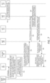
- Figure 8 is a communication flow diagram illustrating aspects of one possible approach to handling intra-ADU IP frames within a QFI, according to some embodiments. As shown, the illustrated communication flow may be performed between a UE PDCP entity 802, a UE RLC entity 804, a NG-RAN RLC entity 806, and a NG-RAN PDCP entity 808.
- a first ADU (“ADU #1”) 810 may include the PDCP SNs #1, #2, and #3.
- a second ADU (“ADU #2”) 812 may include the PDCP SNs #4 and #5.
- the PDCP SN #1 may be unable to be transmitted, and as the PDCP SN #2 and #3 are from the same ADU as SN #1, in 814, the UE may also discard these PDUs without attempting transmission.
- the UE PDCP 802 may provide a PDCP Status Report indicating that SN #2 and SN #3 are skipped to the NG-RAN PDCP 808.
- the PDCP SN #4 and SN #5 of the second ADU 812 may be handled independently from the PDCP SN #1, #2, and #3, e.g., since they belong to a different ADU.
- a smart automatic repeat request (ARQ) approach based on interested packets in the uplink may be used.
- ARQ automatic repeat request
- the UE may employ the smart ARQ mechanism to avoid further delay.
- the UE RLC may drop the RLC PDUs carrying the PDCP PDU SN #2 and SN #3 locally and may send a RLC status report to indicate the skipped SNs to the NG-RAN RLC.
- a similar smart ARQ approach based on interested packets in the downlink may also be used.
- the gNB may employ the smart ARQ mechanism to avoid further delay.
- the gNB RLC may drop the RLC PDUs carrying the PDCP PDU SN #2 and SN #3 locally and may send a RLC status report to indicate the skipped SNs to the UE RLC.
- Such mechanisms may allow the corresponding entities (e.g., NR-RAN RLC in the uplink scenario or UE RLC in the downlink scenario) to stop waiting for any skipped packets before providing successfully received packets with subsequent SNs to the PDCP for in-order delivery, at least according to some embodiments.
- One set of embodiments may include an apparatus, comprising: a processor configured to cause a wireless device to: establish a service data flow (SDF) with an application function (AF) via a cellular network; determine that the SDF includes at least two categories of data, wherein a first category of data for the SDF has different Quality of Service (QoS) parameters than a second category of data for the SDF; communicate the first category of data for the SDF using a first QoS Flow; and communicate the second category of data for the SDF using a second QoS Flow, wherein the first category of data for the SDF and the second category of data for the SDF are communicated using different QoS Flows based at least in part on determining that the first category of data for the SDF has different QoS parameters than the second category of data for the SDF.
- SDF service data flow
- AF application function
- the processor is further configured to cause the wireless device to: parse packets of the SDF according to a packet filter to determine whether the packets of the SDF are associated with the first category of data for the SDF or the second category of data for the SDF.
- the packet filter determines whether the packets of the SDF are associated with the first category of data for the SDF or the second category of data for the SDF based on one or more of: Internet Protocol (IP) header information indicating Traffic Class or Type of Service (ToS); IPv6 Flow Type information; IP Security (IPSec) header Security parameters index information; or an offset value indicating a location of category information in packets of the SDF.
- IP Internet Protocol
- ToS Traffic Class or Type of Service
- IPv6 Flow Type information IP Security (IPSec) header Security parameters index information
- an offset value indicating a location of category information in packets of the SDF.
- the processor is further configured to cause the wireless device to: provide an indication to the cellular network of a relationship between the first QoS Flow and the second QoS Flow.
- the processor is further configured to cause the wireless device to: determine that a first uplink packet of the first QoS Flow is not successfully transmitted at a packet data convergence protocol (PDCP) layer of the wireless device; determine that a second uplink packet of the first QoS Flow is dependent on the first uplink packet of the first QoS Flow; and drop the second uplink packet of the first QoS Flow at the PDCP layer of the wireless device based at least in part on the second uplink packet of the first QoS Flow being dependent on the first uplink packet of the first QoS Flow.
- PDCP packet data convergence protocol
- determining that the second uplink packet of the first QoS Flow is dependent on the first uplink packet of the first QoS Flow is based on packet descriptor information included in the first uplink packet of the first QoS Flow and the second uplink packet of the first QoS Flow.
- the processor is further configured to cause the wireless device to perform one or more of: providing an indication that the second uplink packet of the first QoS Flow is dropped at the PDCP layer of the wireless device to the cellular network; re-numbering PDCP sequence numbers (SNs) at the PDCP layer of the wireless device; or creating a dummy PDCP packet with a PDCP SN corresponding to a PDCP SN of the second uplink packet of the first QoS Flow at the PDCP layer of the wireless device.
- SNs PDCP sequence numbers
- the processor is further configured to cause the wireless device to: determine that a first uplink packet of the first QoS Flow is not successfully transmitted at a radio link control (RLC) layer of the wireless device; determine that a second uplink packet of the first QoS Flow is dependent on the first uplink packet of the first QoS Flow; drop the second uplink packet of the first QoS Flow at the RLC layer of the wireless device based at least in part on the second uplink packet of the first QoS Flow being dependent on the first uplink packet of the first QoS Flow; and provide an indication that the second uplink packet of the first QoS Flow is dropped at the RLC layer of the wireless device to the cellular network.
- RLC radio link control
- the processor is further configured to cause the wireless device to: receive an indication of one or more packet sequence numbers that are not transmitted to the wireless device by the cellular network at a packet data convergence protocol (PDCP) layer or a radio link control (RLC) layer of the wireless device.
- PDCP packet data convergence protocol
- RLC radio link control
- Another set of embodiments may include a cellular network element, comprising: a processor; and a network interface operably coupled to the processor, wherein the cellular network element is configured to: determine that a service data flow (SDF) between an application function (AF) and a wireless device includes at least two categories of packets, wherein a first category of packets of the SDF has different Quality of Service (QoS) parameters than a second category of packets of the SDF; establish a first QoS Flow for the first category of packets of the SDF; and establish a second QoS Flow for the second category of packets of the SDF.
- SDF service data flow
- AF application function
- QoS Quality of Service
- the cellular network element is further configured to: provide downlink packet detection rules for the SDF to a second cellular network element and uplink packet filter information to the wireless device, wherein the downlink packet detection rules and uplink packet filter information are configured for determining whether packets of the SDF are associated with the first category of packets of the SDF or the second category of packets of the SDF, wherein the downlink packet detection rules and the uplink packet filter information are based on one or more of: Internet Protocol (IP) header information indicating Traffic Class or Type of Service (ToS) for the packets of the SDF; IPv6 Flow Type information for the packets of the SDF; IP Security (IPSec) header Security parameters index information for the packets of the SDF; or an offset value indicating a location of category information in the packets of the SDF.
- IP Internet Protocol
- ToS Traffic Class or Type of Service
- IPv6 Flow Type information for the packets of the SDF
- the cellular network element is further configured to: determine a relationship between the first QoS Flow and the second QoS Flow; and provide an indication of the relationship between the first QoS Flow and the second QoS Flow to a second cellular network element.
- the cellular network element is further configured to: receive an indication of the relationship between the first QoS Flow and the second QoS Flow from the wireless device.
- the cellular network element is further configured to: verify whether the relationship between the first QoS Flow and the second QoS Flow is allowed according to one or more cellular network policies.
- Yet another set of embodiments may include a cellular base station, comprising: an antenna; a radio operably coupled to the antenna; and a processor operably coupled to the radio; wherein the cellular base station is configured to: establish a wireless link with a wireless device; transmit first packets to the wireless device on the wireless link using a first QoS Flow; and transmit second packets to the wireless device on the wireless link using a second QoS Flow, wherein both the first packets and the second packets are associated with a service data flow (SDF).
- SDF service data flow
- the cellular base station is further configured to: receive an indication of a relationship between the first QoS Flow and the second QoS Flow; and perform scheduling for one or more of downlink communications or uplink communications for the first QoS Flow and the second QoS Flow based at least in part on the relationship between the first QoS Flow and the second QoS Flow.
- the cellular base station is further configured to: determine that a first downlink packet of the first QoS Flow is not successfully transmitted; determine that a second downlink packet of the first QoS Flow is dependent on the first downlink packet of the first QoS Flow; and drop the second downlink packet of the first QoS Flow based at least in part on the second downlink packet of the first QoS Flow being dependent on the first downlink packet of the first QoS Flow.
- the second downlink packet of the first QoS Flow is dropped at one of a packet data convergence protocol (PDCP) layer or a radio link control (RLC) layer of the cellular base station, wherein the cellular base station is further configured to: provide an indication to the wireless device that the second downlink packet of the first QoS Flow is dropped at one of the PDCP layer or the RLC layer of the cellular base station.
- PDCP packet data convergence protocol
- RLC radio link control
- determining that the second downlink packet of the first QoS Flow is dependent on the first downlink packet of the first QoS Flow is based on header information included in the first downlink packet of the first QoS Flow and the second downlink packet of the first QoS Flow.
- the cellular base station is further configured to: receive an indication of one or packet sequence numbers that are not transmitted to the cellular base station by the wireless device at a packet data convergence protocol (PDCP) layer or a radio link control (RLC) layer of the cellular base station.
- PDCP packet data convergence protocol
- RLC radio link control
- a further exemplary embodiment may include a method, comprising: performing, by a device, any or all parts of the preceding examples.
- Another exemplary embodiment may include a device, comprising: an antenna; a radio coupled to the antenna; and a processing element operably coupled to the radio, wherein the device is configured to implement any or all parts of the preceding examples.
- a further exemplary set of embodiments may include a non-transitory computer accessible memory medium comprising program instructions which, when executed at a device, cause the device to implement any or all parts of any of the preceding examples.
- a still further exemplary set of embodiments may include a computer program comprising instructions for performing any or all parts of any of the preceding examples.
- Yet another exemplary set of embodiments may include an apparatus comprising means for performing any or all of the elements of any of the preceding examples.
- Still another exemplary set of embodiments may include an apparatus comprising a processing element configured to cause a wireless device to perform any or all of the elements of any of the preceding examples.
- personally identifiable information should follow privacy policies and practices that are generally recognized as meeting or exceeding industry or governmental requirements for maintaining the privacy of users.
- personally identifiable information data should be managed and handled so as to minimize risks of unintentional or unauthorized access or use, and the nature of authorized use should be clearly indicated to users.
- Any of the methods described herein for operating a user equipment may be the basis of a corresponding method for operating a base station, by interpreting each message/signal X received by the UE in the downlink as message/signal X transmitted by the base station, and each message/signal Y transmitted in the uplink by the UE as a message/signal Y received by the base station.
- Embodiments of the present disclosure may be realized in any of various forms.
- the present subject matter may be realized as a computerimplemented method, a computer-readable memory medium, or a computer system.
- the present subject matter may be realized using one or more custom-designed hardware devices such as ASICs.
- the present subject matter may be realized using one or more programmable hardware elements such as FPGAs.
- a non-transitory computer-readable memory medium e.g., a non-transitory memory element
- a non-transitory computer-readable memory medium may be configured so that it stores program instructions and/or data, where the program instructions, if executed by a computer system, cause the computer system to perform a method, e.g., any of a method embodiments described herein, or, any combination of the method embodiments described herein, or, any subset of any of the method embodiments described herein, or, any combination of such subsets.
- a device e.g., a UE
- a device may be configured to include a processor (or a set of processors) and a memory medium (or memory element), where the memory medium stores program instructions, where the processor is configured to read and execute the program instructions from the memory medium, where the program instructions are executable to implement any of the various method embodiments described herein (or, any combination of the method embodiments described herein, or, any subset of any of the method embodiments described herein, or, any combination of such subsets).
- the device may be realized in any of various forms.
Landscapes
- Engineering & Computer Science (AREA)
- Computer Networks & Wireless Communication (AREA)
- Signal Processing (AREA)
- Mobile Radio Communication Systems (AREA)
- Quality & Reliability (AREA)
- Computer Security & Cryptography (AREA)
Applications Claiming Priority (2)
| Application Number | Priority Date | Filing Date | Title |
|---|---|---|---|
| US202163240302P | 2021-09-02 | 2021-09-02 | |
| US17/882,765 US12439291B2 (en) | 2021-09-02 | 2022-08-08 | Quality of service framework enhancements for 5G service |
Publications (2)
| Publication Number | Publication Date |
|---|---|
| EP4145802A1 true EP4145802A1 (de) | 2023-03-08 |
| EP4145802B1 EP4145802B1 (de) | 2026-02-25 |
Family
ID=83318979
Family Applications (1)
| Application Number | Title | Priority Date | Filing Date |
|---|---|---|---|
| EP22190260.4A Active EP4145802B1 (de) | 2021-09-02 | 2022-08-12 | Dienstgüterahmenverbesserungen für 5g-dienst |
Country Status (5)
| Country | Link |
|---|---|
| US (1) | US12439291B2 (de) |
| EP (1) | EP4145802B1 (de) |
| KR (1) | KR102880119B1 (de) |
| CN (1) | CN115767632A (de) |
| FI (1) | FI4145802T3 (de) |
Cited By (1)
| Publication number | Priority date | Publication date | Assignee | Title |
|---|---|---|---|---|
| WO2023129475A1 (en) * | 2021-12-29 | 2023-07-06 | Ofinno, Llc | Data unit in wireless system |
Families Citing this family (7)
| Publication number | Priority date | Publication date | Assignee | Title |
|---|---|---|---|---|
| US12015960B1 (en) * | 2021-09-02 | 2024-06-18 | T-Mobile Innovations Llc | System and method for redirection to optimal antenna arrays |
| US12531671B2 (en) * | 2022-01-31 | 2026-01-20 | Qualcomm Incorporated | Techniques for application data unit signaling |
| US20240073734A1 (en) * | 2022-08-23 | 2024-02-29 | Meta Platforms Technologies, Llc | Systems and methods of control of quality-of-service of data units via multiple communication layers |
| WO2024239147A1 (en) * | 2023-05-19 | 2024-11-28 | Nokia Shanghai Bell Co., Ltd. | Coordination for round-trip communications |
| CN121359577A (zh) * | 2024-05-16 | 2026-01-16 | 北京小米移动软件有限公司 | 通信方法和装置、通信设备、通信系统及存储介质 |
| CN120980709A (zh) * | 2024-05-16 | 2025-11-18 | 维沃移动通信有限公司 | 无线通信方法、装置、设备以及可读存储介质 |
| WO2026036744A1 (en) * | 2024-08-14 | 2026-02-19 | Huawei Technologies Co., Ltd. | New layer for qos management on data processing and forwarding |
Citations (2)
| Publication number | Priority date | Publication date | Assignee | Title |
|---|---|---|---|---|
| US20080123660A1 (en) * | 2006-08-09 | 2008-05-29 | Interdigital Technology Corporation | Method and apparatus for providing differentiated quality of service for packets in a particular flow |
| CN112804711A (zh) * | 2021-01-04 | 2021-05-14 | 腾讯科技(深圳)有限公司 | 数据传输方法、装置、计算机可读介质及电子设备 |
Family Cites Families (8)
| Publication number | Priority date | Publication date | Assignee | Title |
|---|---|---|---|---|
| US20130326034A1 (en) * | 2012-05-30 | 2013-12-05 | Alcatel-Lucent Canada Inc. | Pcrf rule rollback due to insufficient resources on a downstream node |
| WO2016003805A1 (en) | 2014-06-30 | 2016-01-07 | Intel IP Corporation | An apparatus and method enhancing quality of service architecture for lte |
| WO2018128452A1 (en) * | 2017-01-06 | 2018-07-12 | Lg Electronics Inc. | Method for transmitting lossless data packet based on quality of service (qos) framework in wireless communication system and a device therefor |
| CN110463254B (zh) | 2017-03-22 | 2022-11-22 | Lg电子株式会社 | 用于在无线通信系统中基于服务质量(QoS)框架发送UL分组的方法及其设备 |
| EP4496287A3 (de) * | 2017-05-09 | 2025-04-02 | Huawei Technologies Co., Ltd. | Qos-steuerungsverfahren und -vorrichtung |
| KR102384282B1 (ko) * | 2017-06-09 | 2022-04-07 | 삼성전자주식회사 | 무선 통신 시스템에서 혼잡을 제어하기 위한 장치 및 방법 |
| CN110636544B (zh) * | 2018-06-22 | 2022-09-23 | 华为技术有限公司 | 一种数据传输方法及装置 |
| US11558778B2 (en) | 2019-06-07 | 2023-01-17 | Qualcomm Incorporated | Techniques for file aware communications |
-
2022
- 2022-08-08 US US17/882,765 patent/US12439291B2/en active Active
- 2022-08-12 EP EP22190260.4A patent/EP4145802B1/de active Active
- 2022-08-12 FI FIEP22190260.4T patent/FI4145802T3/fi active
- 2022-09-01 KR KR1020220110524A patent/KR102880119B1/ko active Active
- 2022-09-01 CN CN202211065324.4A patent/CN115767632A/zh active Pending
Patent Citations (2)
| Publication number | Priority date | Publication date | Assignee | Title |
|---|---|---|---|---|
| US20080123660A1 (en) * | 2006-08-09 | 2008-05-29 | Interdigital Technology Corporation | Method and apparatus for providing differentiated quality of service for packets in a particular flow |
| CN112804711A (zh) * | 2021-01-04 | 2021-05-14 | 腾讯科技(深圳)有限公司 | 数据传输方法、装置、计算机可读介质及电子设备 |
Cited By (3)
| Publication number | Priority date | Publication date | Assignee | Title |
|---|---|---|---|---|
| WO2023129475A1 (en) * | 2021-12-29 | 2023-07-06 | Ofinno, Llc | Data unit in wireless system |
| US12010202B2 (en) | 2021-12-29 | 2024-06-11 | Ofinno, Llc | Data unit in wireless system |
| US12375590B2 (en) | 2021-12-29 | 2025-07-29 | Ofinno, Llc | Data unit identification |
Also Published As
| Publication number | Publication date |
|---|---|
| FI4145802T3 (fi) | 2026-04-21 |
| KR102880119B1 (ko) | 2025-11-04 |
| CN115767632A (zh) | 2023-03-07 |
| KR20230034176A (ko) | 2023-03-09 |
| EP4145802B1 (de) | 2026-02-25 |
| US20230069008A1 (en) | 2023-03-02 |
| US12439291B2 (en) | 2025-10-07 |
Similar Documents
| Publication | Publication Date | Title |
|---|---|---|
| EP4145802B1 (de) | Dienstgüterahmenverbesserungen für 5g-dienst | |
| US11659512B2 (en) | Knowledge of slice quota availability for a UE | |
| US12213031B2 (en) | Point to point and point to multipoint switching with service continuity for broadcast and multicast service | |
| US20220322078A1 (en) | Split Bearer Communications | |
| US11991562B2 (en) | Multicast and broadcast services (MBS) mobility with service continuity in connected state | |
| US10966248B2 (en) | Coexistence features for cellular communication in unlicensed spectrum | |
| EP3993489A1 (de) | Reflexive qos-verbesserungen | |
| US12407464B2 (en) | Resource counting for reference signals | |
| US12120552B2 (en) | Enhanced packet filtering | |
| US20240155573A1 (en) | Time Domain Resource Selection | |
| US12063664B2 (en) | Multiplexing of uplink transmissions | |
| WO2025020127A1 (en) | Ue behavior relating to psi-based packet discarding | |
| US12532213B2 (en) | Communication coordination and reduced processing techniques for enhanced quality of service procedures | |
| US11470679B1 (en) | Framework for supporting custom signaling between a wireless device and a cellular network | |
| US20260032494A1 (en) | Fast Channel State Information Reporting Configuration Updates for Neighbor Cells | |
| EP4666688A1 (de) | Versatzinformationsspeicherung für nachbarzellen | |
| EP4666518A1 (de) | Konfiguration eines übertragungssteuerungsindikatorzustands für nachbarzellen |
Legal Events
| Date | Code | Title | Description |
|---|---|---|---|
| PUAI | Public reference made under article 153(3) epc to a published international application that has entered the european phase |
Free format text: ORIGINAL CODE: 0009012 |
|
| STAA | Information on the status of an ep patent application or granted ep patent |
Free format text: STATUS: REQUEST FOR EXAMINATION WAS MADE |
|
| 17P | Request for examination filed |
Effective date: 20220812 |
|
| AK | Designated contracting states |
Kind code of ref document: A1 Designated state(s): AL AT BE BG CH CY CZ DE DK EE ES FI FR GB GR HR HU IE IS IT LI LT LU LV MC MK MT NL NO PL PT RO RS SE SI SK SM TR |
|
| REG | Reference to a national code |
Ref country code: DE Free format text: PREVIOUS MAIN CLASS: H04L0047240800 Ref country code: DE Ref legal event code: R079 Ref document number: 602022031001 Country of ref document: DE Free format text: PREVIOUS MAIN CLASS: H04L0047240800 Ipc: H04W0028020000 |
|
| GRAP | Despatch of communication of intention to grant a patent |
Free format text: ORIGINAL CODE: EPIDOSNIGR1 |
|
| STAA | Information on the status of an ep patent application or granted ep patent |
Free format text: STATUS: GRANT OF PATENT IS INTENDED |
|
| RIC1 | Information provided on ipc code assigned before grant |
Ipc: H04W 28/02 20090101AFI20250909BHEP Ipc: H04L 5/00 20060101ALN20250909BHEP Ipc: H04L 69/22 20220101ALN20250909BHEP |
|
| INTG | Intention to grant announced |
Effective date: 20250922 |
|
| RIC1 | Information provided on ipc code assigned before grant |
Ipc: H04W 28/02 20090101AFI20250915BHEP Ipc: H04L 5/00 20060101ALN20250915BHEP Ipc: H04L 69/22 20220101ALN20250915BHEP |
|
| GRAS | Grant fee paid |
Free format text: ORIGINAL CODE: EPIDOSNIGR3 |
|
| P01 | Opt-out of the competence of the unified patent court (upc) registered |
Free format text: CASE NUMBER: UPC_APP_0017462_4145802/2025 Effective date: 20251212 |
|
| GRAA | (expected) grant |
Free format text: ORIGINAL CODE: 0009210 |
|
| STAA | Information on the status of an ep patent application or granted ep patent |
Free format text: STATUS: THE PATENT HAS BEEN GRANTED |
|
| AK | Designated contracting states |
Kind code of ref document: B1 Designated state(s): AL AT BE BG CH CY CZ DE DK EE ES FI FR GB GR HR HU IE IS IT LI LT LU LV MC MK MT NL NO PL PT RO RS SE SI SK SM TR |
|
| REG | Reference to a national code |
Ref country code: CH Ref legal event code: F10 Free format text: ST27 STATUS EVENT CODE: U-0-0-F10-F00 (AS PROVIDED BY THE NATIONAL OFFICE) Effective date: 20260225 Ref country code: GB Ref legal event code: FG4D |
|
| REG | Reference to a national code |
Ref country code: DE Ref legal event code: R096 Ref document number: 602022031001 Country of ref document: DE |
|
| REG | Reference to a national code |
Ref country code: IE Ref legal event code: FG4D |
|
| REG | Reference to a national code |
Ref country code: FI Ref legal event code: FGE |