EP4145688A1 - Power converter and control method thereof - Google Patents
Power converter and control method thereof Download PDFInfo
- Publication number
- EP4145688A1 EP4145688A1 EP22193209.8A EP22193209A EP4145688A1 EP 4145688 A1 EP4145688 A1 EP 4145688A1 EP 22193209 A EP22193209 A EP 22193209A EP 4145688 A1 EP4145688 A1 EP 4145688A1
- Authority
- EP
- European Patent Office
- Prior art keywords
- input
- controller
- power
- parameter
- set value
- Prior art date
- Legal status (The legal status is an assumption and is not a legal conclusion. Google has not performed a legal analysis and makes no representation as to the accuracy of the status listed.)
- Pending
Links
- 238000000034 method Methods 0.000 title claims description 26
- 239000003990 capacitor Substances 0.000 claims abstract description 61
- 230000002457 bidirectional effect Effects 0.000 claims description 4
- 238000004804 winding Methods 0.000 description 6
- 230000007423 decrease Effects 0.000 description 5
- 238000010586 diagram Methods 0.000 description 4
- 238000004891 communication Methods 0.000 description 1
- 238000005516 engineering process Methods 0.000 description 1
- 230000003071 parasitic effect Effects 0.000 description 1
Images



Classifications
-
- H—ELECTRICITY
- H02—GENERATION; CONVERSION OR DISTRIBUTION OF ELECTRIC POWER
- H02M—APPARATUS FOR CONVERSION BETWEEN AC AND AC, BETWEEN AC AND DC, OR BETWEEN DC AND DC, AND FOR USE WITH MAINS OR SIMILAR POWER SUPPLY SYSTEMS; CONVERSION OF DC OR AC INPUT POWER INTO SURGE OUTPUT POWER; CONTROL OR REGULATION THEREOF
- H02M1/00—Details of apparatus for conversion
- H02M1/0067—Converter structures employing plural converter units, other than for parallel operation of the units on a single load
- H02M1/0074—Plural converter units whose inputs are connected in series
-
- H—ELECTRICITY
- H02—GENERATION; CONVERSION OR DISTRIBUTION OF ELECTRIC POWER
- H02M—APPARATUS FOR CONVERSION BETWEEN AC AND AC, BETWEEN AC AND DC, OR BETWEEN DC AND DC, AND FOR USE WITH MAINS OR SIMILAR POWER SUPPLY SYSTEMS; CONVERSION OF DC OR AC INPUT POWER INTO SURGE OUTPUT POWER; CONTROL OR REGULATION THEREOF
- H02M3/00—Conversion of DC power input into DC power output
- H02M3/22—Conversion of DC power input into DC power output with intermediate conversion into AC
- H02M3/24—Conversion of DC power input into DC power output with intermediate conversion into AC by static converters
- H02M3/28—Conversion of DC power input into DC power output with intermediate conversion into AC by static converters using discharge tubes with control electrode or semiconductor devices with control electrode to produce the intermediate AC
- H02M3/325—Conversion of DC power input into DC power output with intermediate conversion into AC by static converters using discharge tubes with control electrode or semiconductor devices with control electrode to produce the intermediate AC using devices of a triode or a transistor type requiring continuous application of a control signal
- H02M3/335—Conversion of DC power input into DC power output with intermediate conversion into AC by static converters using discharge tubes with control electrode or semiconductor devices with control electrode to produce the intermediate AC using devices of a triode or a transistor type requiring continuous application of a control signal using semiconductor devices only
- H02M3/33569—Conversion of DC power input into DC power output with intermediate conversion into AC by static converters using discharge tubes with control electrode or semiconductor devices with control electrode to produce the intermediate AC using devices of a triode or a transistor type requiring continuous application of a control signal using semiconductor devices only having several active switching elements
- H02M3/33576—Conversion of DC power input into DC power output with intermediate conversion into AC by static converters using discharge tubes with control electrode or semiconductor devices with control electrode to produce the intermediate AC using devices of a triode or a transistor type requiring continuous application of a control signal using semiconductor devices only having several active switching elements having at least one active switching element at the secondary side of an isolation transformer
- H02M3/33584—Bidirectional converters
-
- H—ELECTRICITY
- H02—GENERATION; CONVERSION OR DISTRIBUTION OF ELECTRIC POWER
- H02M—APPARATUS FOR CONVERSION BETWEEN AC AND AC, BETWEEN AC AND DC, OR BETWEEN DC AND DC, AND FOR USE WITH MAINS OR SIMILAR POWER SUPPLY SYSTEMS; CONVERSION OF DC OR AC INPUT POWER INTO SURGE OUTPUT POWER; CONTROL OR REGULATION THEREOF
- H02M1/00—Details of apparatus for conversion
- H02M1/32—Means for protecting converters other than automatic disconnection
-
- H—ELECTRICITY
- H02—GENERATION; CONVERSION OR DISTRIBUTION OF ELECTRIC POWER
- H02M—APPARATUS FOR CONVERSION BETWEEN AC AND AC, BETWEEN AC AND DC, OR BETWEEN DC AND DC, AND FOR USE WITH MAINS OR SIMILAR POWER SUPPLY SYSTEMS; CONVERSION OF DC OR AC INPUT POWER INTO SURGE OUTPUT POWER; CONTROL OR REGULATION THEREOF
- H02M3/00—Conversion of DC power input into DC power output
- H02M3/01—Resonant DC/DC converters
-
- H—ELECTRICITY
- H02—GENERATION; CONVERSION OR DISTRIBUTION OF ELECTRIC POWER
- H02M—APPARATUS FOR CONVERSION BETWEEN AC AND AC, BETWEEN AC AND DC, OR BETWEEN DC AND DC, AND FOR USE WITH MAINS OR SIMILAR POWER SUPPLY SYSTEMS; CONVERSION OF DC OR AC INPUT POWER INTO SURGE OUTPUT POWER; CONTROL OR REGULATION THEREOF
- H02M3/00—Conversion of DC power input into DC power output
- H02M3/22—Conversion of DC power input into DC power output with intermediate conversion into AC
- H02M3/24—Conversion of DC power input into DC power output with intermediate conversion into AC by static converters
- H02M3/28—Conversion of DC power input into DC power output with intermediate conversion into AC by static converters using discharge tubes with control electrode or semiconductor devices with control electrode to produce the intermediate AC
- H02M3/285—Single converters with a plurality of output stages connected in parallel
-
- H—ELECTRICITY
- H02—GENERATION; CONVERSION OR DISTRIBUTION OF ELECTRIC POWER
- H02M—APPARATUS FOR CONVERSION BETWEEN AC AND AC, BETWEEN AC AND DC, OR BETWEEN DC AND DC, AND FOR USE WITH MAINS OR SIMILAR POWER SUPPLY SYSTEMS; CONVERSION OF DC OR AC INPUT POWER INTO SURGE OUTPUT POWER; CONTROL OR REGULATION THEREOF
- H02M3/00—Conversion of DC power input into DC power output
- H02M3/22—Conversion of DC power input into DC power output with intermediate conversion into AC
- H02M3/24—Conversion of DC power input into DC power output with intermediate conversion into AC by static converters
- H02M3/28—Conversion of DC power input into DC power output with intermediate conversion into AC by static converters using discharge tubes with control electrode or semiconductor devices with control electrode to produce the intermediate AC
- H02M3/325—Conversion of DC power input into DC power output with intermediate conversion into AC by static converters using discharge tubes with control electrode or semiconductor devices with control electrode to produce the intermediate AC using devices of a triode or a transistor type requiring continuous application of a control signal
- H02M3/335—Conversion of DC power input into DC power output with intermediate conversion into AC by static converters using discharge tubes with control electrode or semiconductor devices with control electrode to produce the intermediate AC using devices of a triode or a transistor type requiring continuous application of a control signal using semiconductor devices only
- H02M3/33569—Conversion of DC power input into DC power output with intermediate conversion into AC by static converters using discharge tubes with control electrode or semiconductor devices with control electrode to produce the intermediate AC using devices of a triode or a transistor type requiring continuous application of a control signal using semiconductor devices only having several active switching elements
- H02M3/33573—Full-bridge at primary side of an isolation transformer
-
- H—ELECTRICITY
- H02—GENERATION; CONVERSION OR DISTRIBUTION OF ELECTRIC POWER
- H02M—APPARATUS FOR CONVERSION BETWEEN AC AND AC, BETWEEN AC AND DC, OR BETWEEN DC AND DC, AND FOR USE WITH MAINS OR SIMILAR POWER SUPPLY SYSTEMS; CONVERSION OF DC OR AC INPUT POWER INTO SURGE OUTPUT POWER; CONTROL OR REGULATION THEREOF
- H02M1/00—Details of apparatus for conversion
- H02M1/0003—Details of control, feedback or regulation circuits
- H02M1/0032—Control circuits allowing low power mode operation, e.g. in standby mode
- H02M1/0035—Control circuits allowing low power mode operation, e.g. in standby mode using burst mode control
-
- Y—GENERAL TAGGING OF NEW TECHNOLOGICAL DEVELOPMENTS; GENERAL TAGGING OF CROSS-SECTIONAL TECHNOLOGIES SPANNING OVER SEVERAL SECTIONS OF THE IPC; TECHNICAL SUBJECTS COVERED BY FORMER USPC CROSS-REFERENCE ART COLLECTIONS [XRACs] AND DIGESTS
- Y02—TECHNOLOGIES OR APPLICATIONS FOR MITIGATION OR ADAPTATION AGAINST CLIMATE CHANGE
- Y02B—CLIMATE CHANGE MITIGATION TECHNOLOGIES RELATED TO BUILDINGS, e.g. HOUSING, HOUSE APPLIANCES OR RELATED END-USER APPLICATIONS
- Y02B70/00—Technologies for an efficient end-user side electric power management and consumption
- Y02B70/10—Technologies improving the efficiency by using switched-mode power supplies [SMPS], i.e. efficient power electronics conversion e.g. power factor correction or reduction of losses in power supplies or efficient standby modes
Definitions
- the present disclosure relates to a power converter, and more particularly to a power converter and a control method thereof.
- ISOP input-series-output-parallel converters
- the ISOP converter includes plural DC/DC modules with input terminals connected in series and output terminals connected in parallel.
- the difficulty of applying the ISOP converter is to realize the input voltage equalization control between the plural DC/DC modules.
- the ISOP converter can utilize the power loop of the system to adjust the power of each DC/DC module, so as to realize the input voltage equalization.
- the adjusting ability of the power loop is strong, thus it is easy to realize the input voltage equalization.
- the adjusting ability of the power loop is limited, thus it is difficult to realize the input voltage equalization.
- the DC/DC module is usually implemented with LLC resonant topology.
- the DC/DC module implemented with LLC resonant topology operates in frequency modulation mode.
- the DC/DC module operates in burst mode. Under this circumstance, the parasitic parameters of the DC/DC module cannot be ignored, which makes the gain curve oscillate and further causes non-monotonicity and instability of control.
- the present disclosure provides a power converter and a control method thereof.
- the switching frequency of the power unit is adjusted immediately. Accordingly, the voltage on the input capacitor decreases rapidly, thus the overvoltage on the input capacitor is avoided, the components of the power converter is prevented from being damaged, and the power converter can keep working.
- a power converter includes a plurality of power units and a plurality of local controller.
- Each power unit includes an input capacitor. Input terminals of the plurality of power units are connected to each other in series. Output terminals of the plurality of power units are connected to each other in parallel.
- the plurality of local controllers are electrically connected to the plurality of power units respectively.
- Each local controller is configured to control an operation of switching devices in the corresponding power unit.
- Each local controller receives an input capacitor voltage on the input capacitor of the corresponding power unit, an input reference voltage and an output voltage of the power converter. In each power unit and the corresponding local controller, when an input difference between the input reference voltage and the input capacitor voltage is smaller than a first set value, the local controller controls a switching frequency of the switching devices in the corresponding power unit to jump to a preset frequency.
- a control method configured to control the power converter.
- the control method includes: receiving an input capacitor voltage on the input capacitor of the power unit, an input reference voltage, and an output voltage of the power converter; and when an input difference between the input reference voltage and the input capacitor voltage being smaller than a first set value, controlling a switching frequency of the switching devices in the power unit to jump to a preset frequency.
- FIG. 1 is a schematic block diagram illustrating a power converter according to an embodiment of the present disclosure.
- the power converter 1 of the present disclosure includes a plurality of power units 10 and a plurality of local controllers 20.
- Each power unit 10 includes an input capacitor Cin.
- the input terminals of all the power units 10 are connected to each other in series, and the output terminals of all the power units 10 are connected to each other in parallel.
- the plurality of local controllers 20 are electrically connected to the plurality of power units 10 respectively. That is, each local controller 20 is corresponding to one power unit 10, and each local controller 20 is configured to control the operation of switching devices in the corresponding power unit 10.
- Each local controller 20 receives an input capacitor voltage Vin on the input capacitor Cin of the corresponding power unit 10, an input reference voltage Vinref, and an output voltage Vo of the power converter 1.
- the local controller 20 controls the switching frequency of the switching devices in the corresponding power unit 10 to jump to a preset frequency fsi.
- the input reference voltage Vinref may be set manually or may be a set value from another external controller.
- the switching frequency is adjusted immediately so that the input capacitor voltage Vin decreases rapidly. Accordingly, the input capacitor voltages Vin on the input capacitors Cin of the plurality of power units 10 are equalized, thus the overvoltage on the input capacitor Cin is avoided, the components of the power converter 1 is prevented from being damaged, and the power converter 1 can keep working.
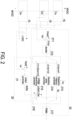
- FIG. 2 schematically shows the local controller 20 corresponding to one of the power units 10 of the power converter 1.
- each local controller 20 includes a calculator 211 and a decider 212.
- the calculator 211 receives the input capacitor voltage Vin and the input reference voltage Vinref, and calculates the input difference ⁇ Vin by comparing the input reference voltage Vinref with the input capacitor voltage Vin.
- the decider 212 receives the input difference ⁇ Vin and compares the input difference ⁇ Vin with the first set value VI and a second set value V2, where the first set value VI is smaller than the second set value V2.
- the local controller 20 controls the power unit 10 correspondingly (e.g., the different controls taken by the local controller 20 are switched through the switch shown in the figure, but not exclusively). Therefore, the voltage equalization between the input capacitors is realized, and the input overvoltage or undervoltage is prevented.
- the different controls taken by the local controller 20 are described in detail as follows.
- each local controller 20 further includes a frequency hopping controller 213.
- the frequency hopping controller 213 In each power unit 10 and the corresponding local controller 20, when the decider 212 determines that the input difference ⁇ Vin is smaller than the first set value V1, the frequency hopping controller 213 generates the preset frequency fsi according to the output voltage Vo, and the local controller 20 controls the switching devices in the corresponding power unit 10 to operate at the preset frequency fsi.
- a plurality of preset frequencies fsi corresponding to different output voltages Vo are preset in the frequency hopping controller 213, and the frequency hopping controller 213 generates the corresponding preset frequency fsi according to the magnitude of the output voltage Vo.
- the plurality of preset frequencies fsi may be different.
- the plurality of preset frequencies fsi may be the same. Since the input difference ⁇ Vin being smaller than the first set value VI means that the input capacitor voltage Vin is too high or close to an input overvoltage protection point, the switching devices are controlled to operate at a relatively low preset frequency fsi (e.g., 80-400 kHz) according to the output voltage Vo. Consequently, the input capacitor voltage Vin decreases rapidly, thereby avoiding the overvoltage occurring on the input capacitor. After the input capacitor voltage Vin returns to be within the normal range, the input voltage equalization control is performed.
- a relatively low preset frequency fsi e.g. 80-400 kHz
- each local controller 20 further includes a disabling pulse controller 214.
- the disabling pulse controller 214 outputs a disabling pulse command.
- the local controller 20 controls the switching devices in the corresponding power unit 10 to stop operating. Since the input difference ⁇ Vin being larger than the second set value V2 means that the input capacitor voltage Vin is too low or close to an input undervoltage protection point, the driving for the switching devices is disabled according to the disabling pulse command, and the switching devices are controlled to stop operating. Consequently, the input undervoltage is avoided. After the input capacitor voltage Vin returns to be within the normal range, the input voltage equalization control is performed.
- the power converter 1 further includes an output controller 31.
- the output controller 31 is configured to receive the output signal, where the output signal may be the output voltage Vo or an output current. Further, the output controller 31 calculates a control base parameter according to a difference between an output reference signal and the output signal, where the output reference signal may be an output reference voltage Voref or an output reference current.
- FIG. 2 schematically shows the situation that the output signal and the output reference signal are the output voltage Vo and the output reference voltage Voref respectively.
- the output controller 31 calculates the control base parameter according to a difference between the output reference voltage Voref and the output voltage Vo.
- the power converter 1 further includes a master controller 30 in communication with the plurality of local controllers 20.
- each local controller 20 further includes a voltage equalizing controller 215 and an operator 216.
- the decider 212 determines that the input difference ⁇ Vin is larger than the first set value VI and is smaller than the second set value V2
- the decider 212 outputs the input difference ⁇ Vin to the voltage equalizing controller 215, and the voltage equalizing controller 215 generates a comparing parameter according to the input difference ⁇ Vin.
- the operator 216 receives the comparing parameter and the control base parameter and calculates a designated parameter accordingly, and the local controller 20 controls the switching devices in the corresponding power unit 10 to operate with the designated parameter.
- the switching devices are controlled to operate with the designated parameter so as to equalize the input voltages.
- the type of the designated parameter varies with the work mode of the power converter 1, which would be described in detail as follow.
- the power unit 10 of the present disclosure is an isolated DC/DC converter and is usually implemented with LLC topology. Under the heavy load, the power converter 1 works in the frequency modulation mode.
- the above-mentioned comparing parameter, control base parameter, and designated parameter are the comparing frequency ⁇ fsi, the control base frequency fs, and the designated frequency respectively.
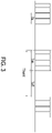
- the switching frequency of the switching devices in the power unit 10 increases correspondingly. As the switching frequency reaches the upper limit that the switching devices can bear, the power unit 10 can't be controlled through frequency modulation anymore. Under this circumstance, the power converter 1 changes to work in the burst mode, and the power converter 1 alternates between in operation for a period of time and out of operation for a period of time.
- Ton is a time period of the power converter 1 being in a working state
- Toff is a time period of the power converter 1 being in a non-working state
- Ts is a switching cycle in the working state
- Tburst is a working cycle in the burst mode
- the effective duty ratio Deff equals Ton/(Ton+Toff).
- the above-mentioned comparing parameter, control base parameter, and designated parameter are the comparing duty ratio ⁇ Dei, the control base duty ratio De, and the designated duty ratio respectively.
- each local controller 20 further includes a PWM (pulse width modulation) generator 217.
- the PWM generator 217 In each power unit 10 and the corresponding local controller 20, corresponding to the magnitude relations between the input difference ⁇ Vin and the first and second set values VI and V2, the PWM generator 217 generates the control signal according to the preset frequency fsi, the disabling pulse command or the designated parameter.
- the control signal is configured to control the operation of the switching devices in the corresponding power unit 10.
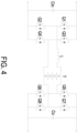
- the power unit 10 is for example but not limited to include the dual-active-bridge bidirectional DC/DC converter shown in FIG. 4 or the full-bridge DC/DC converter shown in FIG. 5 .
- the dual-active-bridge bidirectional DC/DC converter includes a primary circuit, an inductor L, a transformer T, a secondary circuit, and an output capacitor Co.
- the primary circuit includes switching devices Q1 to Q4.
- the serially connected switching devices Q1 and Q2 are connected to the input capacitor Cin in parallel, and the serially connected switching devices Q3 and Q4 are connected to the input capacitor Cin in parallel.
- the inductor L and a primary winding of the transformer T are serially connected between a connection node of the switching devices Q1 and Q2 and a connection node of the switching devices Q3 and Q4.
- the secondary circuit includes switching devices Q5 to Q8.
- the serially connected switching devices Q5 and Q6 are connected to the output capacitor Co in parallel, and the serially connected switching devices Q7 and Q8 are connected to the output capacitor Co in parallel.
- a secondary winding of the transformer T is connected between a connection node of the switching devices Q5 and Q6 and a connection node of the switching devices Q7 and Q8.
- the above-mentioned local controller 20 is configured to control the operation of the switching devices Q1 to Q8. As shown in FIG.
- the full-bridge DC/DC converter includes a primary circuit, a transformer, a secondary circuit, an inductor L, and an output capacitor Co.
- the primary circuit includes switching devices Q1 to Q4.
- the serially connected switching devices Q1 and Q2 are connected to the input capacitor Cin in parallel, and the serially connected switching devices Q3 and Q4 are connected to the input capacitor Cin in parallel.
- a primary winding of the transformer is connected between a connection node of the switching devices Q1 and Q2 and a connection node of the switching devices Q3 and Q4 in series.
- the secondary circuit includes diodes D1 and D2.
- An anode of the diode D1 is connected to a first terminal of a secondary winding of the transformer, an anode of the diode D2 is connected to a second terminal of the secondary winding of the transformer, and a cathode of the diode D2 is connected to a cathode of the diode D1.
- the inductor L is connected between the cathode of the diode D1 and one terminal of the output capacitor Co, and the central point of the secondary winding of the transformer is connected to the other terminal of the output capacitor Co.
- the above-mentioned local controller 20 is configured to control the operation of the switching devices Q1 to Q4.
- FIG. 6 is a schematic flow chart illustrating a control method according to an embodiment of the present disclosure.
- the control method is configured to control the power converter 1 stated above.
- the control method includes steps S1 and S2.
- step S1 the input capacitor voltage Vin of the power unit 10, the input reference voltage Vinref, and the output voltage Vo of the power converter 1 are received.
- step S2 when the input difference ⁇ Vin between the input reference voltage Vinref and the input capacitor voltage Vin is smaller than the first set value V1, the switching frequency of the switching devices in the corresponding power unit 10 is controlled to jump to the preset frequency fsi.
- the control method further includes the steps shown in FIG. 7 .
- the input reference voltage Vinref is compared with the input capacitor voltage Vin to calculate the input difference ⁇ Vin by the calculator 211.
- the input difference ⁇ Vin is compared with the first and second set values V1 and V2 by the decider 212.
- the power unit 10 is controlled correspondingly, so as to realize the input voltage equalization of the plurality of power units 10 and prevent the input overvoltage or undervoltage of each power unit 10, which would be described particularly as follows.
- the step S5 is performed.
- the preset frequency fsi is generated according to the output voltage Vo by the frequency hopping controller 213, and the switching devices in the corresponding power unit 10 are controlled to operate at the preset frequency fsi.
- the step S6 is performed.
- the disabling pulse command is outputted by the disabling pulse controller 214, and the switching devices in the corresponding power unit 10 are controlled to stop operating according to the disabling pulse command.
- the step S7 is performed.
- the input difference ⁇ Vin is outputted to the voltage equalizing controller 215.
- the control base parameter is calculated according to the difference between the output reference voltage Voref and the output voltage Vo by the output controller 31, and the comparing parameter is generated according to the input difference ⁇ Vin by the voltage equalizing controller 215.
- the comparing parameter and the control base parameter are calculated to acquire the designated parameter by the operator 216, and the switching devices in the corresponding power unit 10 are controlled to operate with the designated parameter.
- the control method further includes a step S10.
- the control signal is generated according to the preset frequency fsi, the disabling pulse command or the designated parameter by the PWM generator 217, and the operation of the switching devices in the corresponding power unit 10 are controlled according to the control signal.
- the present disclosure provides a power converter and a control method thereof.
- the power unit is controlled correspondingly, so as to equalize the input voltages of the plurality of power units 10 and prevent the input overvoltage or undervoltage of each power unit 10.
- the switching frequency of the power unit is adjusted immediately. Accordingly, the input capacitor voltage decreases rapidly, thus the overvoltage on the input capacitor is avoided, the components of the power converter is prevented from being damaged, and the power converter keeps working.
- the switching devices are controlled to stop operating through disabling the driving therefor, so as to avoid the input undervoltage.
- the switching devices are controlled to operate with the designated parameter, so as to equalize the input voltages.
- the type of the designated parameter varies with the work mode of the power converter so that the input voltage equalization can be realized under both heavy load and light load.
Landscapes
- Engineering & Computer Science (AREA)
- Power Engineering (AREA)
- Dc-Dc Converters (AREA)
Abstract
Description
- The present disclosure relates to a power converter, and more particularly to a power converter and a control method thereof.
- In high-voltage DC/DC converter applications, ISOP (input-series-output-parallel) converters are widely used. The ISOP converter includes plural DC/DC modules with input terminals connected in series and output terminals connected in parallel. The difficulty of applying the ISOP converter is to realize the input voltage equalization control between the plural DC/DC modules.
- The ISOP converter can utilize the power loop of the system to adjust the power of each DC/DC module, so as to realize the input voltage equalization. When the system works under heavy load, the adjusting ability of the power loop is strong, thus it is easy to realize the input voltage equalization. However, when the system works under light load, the adjusting ability of the power loop is limited, thus it is difficult to realize the input voltage equalization.
- In addition, in order to improve the efficiency of converter, the DC/DC module is usually implemented with LLC resonant topology. When the system works under heavy load, the DC/DC module implemented with LLC resonant topology operates in frequency modulation mode. When the system works under light load, the DC/DC module operates in burst mode. Under this circumstance, the parasitic parameters of the DC/DC module cannot be ignored, which makes the gain curve oscillate and further causes non-monotonicity and instability of control.
- Therefore, when the converter switches between the light load condition and the heavy load condition, the following two problems would be caused. Firstly, under light load, it is difficult to realize the input voltage equalization through adjusting the power loop. Secondly, switching between the frequency modulation mode and the burst mode would bring instability to the converter. Furthermore, if input overvoltage occurs in any of the DC/DC modules during switching the operating modes, the components of the converter would be damaged, which cause the converter breaks down.
- Therefore, there is a need of providing a power converter and a control method thereof in order to overcome the drawbacks of the conventional technologies.
- The present disclosure provides a power converter and a control method thereof. When the voltage on the input capacitor of any power unit is too high or close to an input overvoltage protection point, the switching frequency of the power unit is adjusted immediately. Accordingly, the voltage on the input capacitor decreases rapidly, thus the overvoltage on the input capacitor is avoided, the components of the power converter is prevented from being damaged, and the power converter can keep working.
- In accordance with an aspect of the present disclosure, a power converter is provided. The power converter includes a plurality of power units and a plurality of local controller. Each power unit includes an input capacitor. Input terminals of the plurality of power units are connected to each other in series. Output terminals of the plurality of power units are connected to each other in parallel. The plurality of local controllers are electrically connected to the plurality of power units respectively. Each local controller is configured to control an operation of switching devices in the corresponding power unit. Each local controller receives an input capacitor voltage on the input capacitor of the corresponding power unit, an input reference voltage and an output voltage of the power converter. In each power unit and the corresponding local controller, when an input difference between the input reference voltage and the input capacitor voltage is smaller than a first set value, the local controller controls a switching frequency of the switching devices in the corresponding power unit to jump to a preset frequency.
- In accordance with another aspect of the present disclosure, a control method configured to control the power converter is provided. Regarding each power unit, the control method includes: receiving an input capacitor voltage on the input capacitor of the power unit, an input reference voltage, and an output voltage of the power converter; and when an input difference between the input reference voltage and the input capacitor voltage being smaller than a first set value, controlling a switching frequency of the switching devices in the power unit to jump to a preset frequency.
- The above contents of the present disclosure will become more readily apparent to those ordinarily skilled in the art after reviewing the following detailed description and accompanying drawings, in which:
-
-
FIG. 1 is a schematic block diagram illustrating a power converter according to an embodiment of the present disclosure; -
FIG. 2 schematically shows an output controller of the power converter and a local controller corresponding to one of the power units; -
FIG. 3 schematically shows the operation of the burst mode; -
FIG. 4 is a schematic circuit diagram illustrating a dual-active-bridge bidirectional DC/DC converter; -
FIG. 5 is a schematic circuit diagram illustrating a full-bridge DC/DC converter; -
FIG. 6 andFIG. 7 are schematic flow charts illustrating a control method according to an embodiment of the present disclosure. - The present disclosure will now be described more specifically with reference to the following embodiments. It is to be noted that the following descriptions of preferred embodiments of this disclosure are presented herein for purpose of illustration and description only. It is not intended to be exhaustive or to be limited to the precise form disclosed.
-
FIG. 1 is a schematic block diagram illustrating a power converter according to an embodiment of the present disclosure. As shown inFIG. 1 , thepower converter 1 of the present disclosure includes a plurality ofpower units 10 and a plurality oflocal controllers 20. Eachpower unit 10 includes an input capacitor Cin. The input terminals of all thepower units 10 are connected to each other in series, and the output terminals of all thepower units 10 are connected to each other in parallel. The plurality oflocal controllers 20 are electrically connected to the plurality ofpower units 10 respectively. That is, eachlocal controller 20 is corresponding to onepower unit 10, and eachlocal controller 20 is configured to control the operation of switching devices in thecorresponding power unit 10. Eachlocal controller 20 receives an input capacitor voltage Vin on the input capacitor Cin of thecorresponding power unit 10, an input reference voltage Vinref, and an output voltage Vo of thepower converter 1. In eachpower unit 10 and the correspondinglocal controller 20, when an input difference ΔVin between the input reference voltage Vinref and the input capacitor voltage Vin (ΔVin = Vinref - Vin) is smaller than a first set value V1, thelocal controller 20 controls the switching frequency of the switching devices in thecorresponding power unit 10 to jump to a preset frequency fsi. - In an embodiment, the input reference voltage Vinref may be set manually or may be a set value from another external controller.
- Consequently, when the input capacitor voltage Vin of any
power unit 10 is too high or close to an input overvoltage protection point, the switching frequency is adjusted immediately so that the input capacitor voltage Vin decreases rapidly. Accordingly, the input capacitor voltages Vin on the input capacitors Cin of the plurality ofpower units 10 are equalized, thus the overvoltage on the input capacitor Cin is avoided, the components of thepower converter 1 is prevented from being damaged, and thepower converter 1 can keep working. - Please refer to
FIG. 2. FIG. 2 schematically shows thelocal controller 20 corresponding to one of thepower units 10 of thepower converter 1. As shown inFIG. 2 , eachlocal controller 20 includes acalculator 211 and adecider 212. In eachpower unit 10 and the correspondinglocal controller 20, thecalculator 211 receives the input capacitor voltage Vin and the input reference voltage Vinref, and calculates the input difference ΔVin by comparing the input reference voltage Vinref with the input capacitor voltage Vin. Thedecider 212 receives the input difference ΔVin and compares the input difference ΔVin with the first set value VI and a second set value V2, where the first set value VI is smaller than the second set value V2. In an embodiment, the first set value VI may be the negative of the second set value V2 (i.e., VI = -V2). According to the magnitude relations between the input difference ΔVin and the first and second set values VI and V2, thelocal controller 20 controls thepower unit 10 correspondingly (e.g., the different controls taken by thelocal controller 20 are switched through the switch shown in the figure, but not exclusively). Therefore, the voltage equalization between the input capacitors is realized, and the input overvoltage or undervoltage is prevented. The different controls taken by thelocal controller 20 are described in detail as follows. - In an embodiment, each
local controller 20 further includes afrequency hopping controller 213. In eachpower unit 10 and the correspondinglocal controller 20, when thedecider 212 determines that the input difference ΔVin is smaller than the first set value V1, thefrequency hopping controller 213 generates the preset frequency fsi according to the output voltage Vo, and thelocal controller 20 controls the switching devices in thecorresponding power unit 10 to operate at the preset frequency fsi. In an embodiment, a plurality of preset frequencies fsi corresponding to different output voltages Vo are preset in thefrequency hopping controller 213, and thefrequency hopping controller 213 generates the corresponding preset frequency fsi according to the magnitude of the output voltage Vo. In this embodiment, the plurality of preset frequencies fsi may be different. As an example, the higher the output voltage Vo is, the smaller the corresponding preset frequency fsi is. In another embodiment, the plurality of preset frequencies fsi may be the same. Since the input difference ΔVin being smaller than the first set value VI means that the input capacitor voltage Vin is too high or close to an input overvoltage protection point, the switching devices are controlled to operate at a relatively low preset frequency fsi (e.g., 80-400 kHz) according to the output voltage Vo. Consequently, the input capacitor voltage Vin decreases rapidly, thereby avoiding the overvoltage occurring on the input capacitor. After the input capacitor voltage Vin returns to be within the normal range, the input voltage equalization control is performed. - In an embodiment, each
local controller 20 further includes a disablingpulse controller 214. In eachpower unit 10 and the correspondinglocal controller 20, when thedecider 212 determines that the input difference ΔVin is larger than the second set value V2, the disablingpulse controller 214 outputs a disabling pulse command. According to the disabling pulse command, thelocal controller 20 controls the switching devices in thecorresponding power unit 10 to stop operating. Since the input difference ΔVin being larger than the second set value V2 means that the input capacitor voltage Vin is too low or close to an input undervoltage protection point, the driving for the switching devices is disabled according to the disabling pulse command, and the switching devices are controlled to stop operating. Consequently, the input undervoltage is avoided. After the input capacitor voltage Vin returns to be within the normal range, the input voltage equalization control is performed. - In an embodiment, the
power converter 1 further includes anoutput controller 31. Theoutput controller 31 is configured to receive the output signal, where the output signal may be the output voltage Vo or an output current. Further, theoutput controller 31 calculates a control base parameter according to a difference between an output reference signal and the output signal, where the output reference signal may be an output reference voltage Voref or an output reference current.FIG. 2 schematically shows the situation that the output signal and the output reference signal are the output voltage Vo and the output reference voltage Voref respectively. When theoutput controller 31 receives the output voltage Vo, theoutput controller 31 calculates the control base parameter according to a difference between the output reference voltage Voref and the output voltage Vo. Thepower converter 1 further includes amaster controller 30 in communication with the plurality oflocal controllers 20. Theoutput controller 31 may be a part of themaster controller 30, but not limited thereto. In addition, eachlocal controller 20 further includes avoltage equalizing controller 215 and anoperator 216. In eachpower unit 10 and the correspondinglocal controller 20, when thedecider 212 determines that the input difference ΔVin is larger than the first set value VI and is smaller than the second set value V2, thedecider 212 outputs the input difference ΔVin to thevoltage equalizing controller 215, and thevoltage equalizing controller 215 generates a comparing parameter according to the input difference ΔVin. Theoperator 216 receives the comparing parameter and the control base parameter and calculates a designated parameter accordingly, and thelocal controller 20 controls the switching devices in thecorresponding power unit 10 to operate with the designated parameter. Since the input difference ΔVin being larger than the first set value VI and smaller than the second set value V2 means that the input capacitor voltage Vin is within the normal range, the switching devices are controlled to operate with the designated parameter so as to equalize the input voltages. The type of the designated parameter varies with the work mode of thepower converter 1, which would be described in detail as follow. - The
power unit 10 of the present disclosure is an isolated DC/DC converter and is usually implemented with LLC topology. Under the heavy load, thepower converter 1 works in the frequency modulation mode. Correspondingly, the above-mentioned comparing parameter, control base parameter, and designated parameter are the comparing frequency Δfsi, the control base frequency fs, and the designated frequency respectively. When the load becomes lighter, the switching frequency of the switching devices in thepower unit 10 increases correspondingly. As the switching frequency reaches the upper limit that the switching devices can bear, thepower unit 10 can't be controlled through frequency modulation anymore. Under this circumstance, thepower converter 1 changes to work in the burst mode, and thepower converter 1 alternates between in operation for a period of time and out of operation for a period of time. As shown inFIG. 3 , Ton is a time period of thepower converter 1 being in a working state, Toff is a time period of thepower converter 1 being in a non-working state, Ts is a switching cycle in the working state, Tburst is a working cycle in the burst mode, and the effective duty ratio Deff equals Ton/(Ton+Toff). Correspondingly, when thepower converter 1 works in the burst mode, the above-mentioned comparing parameter, control base parameter, and designated parameter are the comparing duty ratio ΔDei, the control base duty ratio De, and the designated duty ratio respectively. - In addition, in an embodiment, as shown in
FIG. 2 , eachlocal controller 20 further includes a PWM (pulse width modulation)generator 217. In eachpower unit 10 and the correspondinglocal controller 20, corresponding to the magnitude relations between the input difference ΔVin and the first and second set values VI and V2, thePWM generator 217 generates the control signal according to the preset frequency fsi, the disabling pulse command or the designated parameter. The control signal is configured to control the operation of the switching devices in thecorresponding power unit 10. - Further, the
power unit 10 is for example but not limited to include the dual-active-bridge bidirectional DC/DC converter shown inFIG. 4 or the full-bridge DC/DC converter shown inFIG. 5 . As shown inFIG. 4 , the dual-active-bridge bidirectional DC/DC converter includes a primary circuit, an inductor L, a transformer T, a secondary circuit, and an output capacitor Co. The primary circuit includes switching devices Q1 to Q4. The serially connected switching devices Q1 and Q2 are connected to the input capacitor Cin in parallel, and the serially connected switching devices Q3 and Q4 are connected to the input capacitor Cin in parallel. The inductor L and a primary winding of the transformer T are serially connected between a connection node of the switching devices Q1 and Q2 and a connection node of the switching devices Q3 and Q4. The secondary circuit includes switching devices Q5 to Q8. The serially connected switching devices Q5 and Q6 are connected to the output capacitor Co in parallel, and the serially connected switching devices Q7 and Q8 are connected to the output capacitor Co in parallel. A secondary winding of the transformer T is connected between a connection node of the switching devices Q5 and Q6 and a connection node of the switching devices Q7 and Q8. The above-mentionedlocal controller 20 is configured to control the operation of the switching devices Q1 to Q8. As shown inFIG. 5 , the full-bridge DC/DC converter includes a primary circuit, a transformer, a secondary circuit, an inductor L, and an output capacitor Co. The primary circuit includes switching devices Q1 to Q4. The serially connected switching devices Q1 and Q2 are connected to the input capacitor Cin in parallel, and the serially connected switching devices Q3 and Q4 are connected to the input capacitor Cin in parallel. A primary winding of the transformer is connected between a connection node of the switching devices Q1 and Q2 and a connection node of the switching devices Q3 and Q4 in series. The secondary circuit includes diodes D1 and D2. An anode of the diode D1 is connected to a first terminal of a secondary winding of the transformer, an anode of the diode D2 is connected to a second terminal of the secondary winding of the transformer, and a cathode of the diode D2 is connected to a cathode of the diode D1. The inductor L is connected between the cathode of the diode D1 and one terminal of the output capacitor Co, and the central point of the secondary winding of the transformer is connected to the other terminal of the output capacitor Co. The above-mentionedlocal controller 20 is configured to control the operation of the switching devices Q1 to Q4. -
FIG. 6 is a schematic flow chart illustrating a control method according to an embodiment of the present disclosure. The control method is configured to control thepower converter 1 stated above. Regarding eachpower unit 10, as shown inFIG. 6 , the control method includes steps S1 and S2. In the step S1, the input capacitor voltage Vin of thepower unit 10, the input reference voltage Vinref, and the output voltage Vo of thepower converter 1 are received. In the step S2, when the input difference ΔVin between the input reference voltage Vinref and the input capacitor voltage Vin is smaller than the first set value V1, the switching frequency of the switching devices in thecorresponding power unit 10 is controlled to jump to the preset frequency fsi. Consequently, when the input capacitor voltage Vin of anypower unit 10 is too high or close to an input overvoltage protection point, the switching frequency is adjusted immediately so that the input capacitor voltage Vin decreases rapidly. Thus, the overvoltage on the input capacitor Cin is avoided, the components of thepower converter 1 is prevented from being damaged, and thepower converter 1 keeps working. - In an embodiment, the control method further includes the steps shown in
FIG. 7 . As shown inFIG. 7 , firstly, in the step S3, the input reference voltage Vinref is compared with the input capacitor voltage Vin to calculate the input difference ΔVin by thecalculator 211. Then, in the step S4, the input difference ΔVin is compared with the first and second set values V1 and V2 by thedecider 212. Afterwards, according to the magnitude relations between the input difference ΔVin and the first and second set values VI and V2, thepower unit 10 is controlled correspondingly, so as to realize the input voltage equalization of the plurality ofpower units 10 and prevent the input overvoltage or undervoltage of eachpower unit 10, which would be described particularly as follows. - When the
decider 212 determines that the input difference ΔVin is smaller than the first set value V1, the step S5 is performed. In the step S5, the preset frequency fsi is generated according to the output voltage Vo by thefrequency hopping controller 213, and the switching devices in thecorresponding power unit 10 are controlled to operate at the preset frequency fsi. - When the
decider 212 determines that the input difference ΔVin is larger than the second set value V2, the step S6 is performed. In the step S6, the disabling pulse command is outputted by the disablingpulse controller 214, and the switching devices in thecorresponding power unit 10 are controlled to stop operating according to the disabling pulse command. - When the
decider 212 determines that the input difference ΔVin is larger than the first set value VI and is smaller than the second set value V2, the step S7 is performed. In the step S7, the input difference ΔVin is outputted to thevoltage equalizing controller 215. Then, in the step S8, the control base parameter is calculated according to the difference between the output reference voltage Voref and the output voltage Vo by theoutput controller 31, and the comparing parameter is generated according to the input difference ΔVin by thevoltage equalizing controller 215. Afterwards, in the step S9, the comparing parameter and the control base parameter are calculated to acquire the designated parameter by theoperator 216, and the switching devices in thecorresponding power unit 10 are controlled to operate with the designated parameter. - In an embodiment, as shown in
FIG. 7 , the control method further includes a step S10. In the step S10, the control signal is generated according to the preset frequency fsi, the disabling pulse command or the designated parameter by thePWM generator 217, and the operation of the switching devices in thecorresponding power unit 10 are controlled according to the control signal. - In summary, the present disclosure provides a power converter and a control method thereof. According to the magnitude relations between the input difference and the set values, the power unit is controlled correspondingly, so as to equalize the input voltages of the plurality of
power units 10 and prevent the input overvoltage or undervoltage of eachpower unit 10. In particular, when the input capacitor voltage of any power unit is too high or close to an input overvoltage protection point, the switching frequency of the power unit is adjusted immediately. Accordingly, the input capacitor voltage decreases rapidly, thus the overvoltage on the input capacitor is avoided, the components of the power converter is prevented from being damaged, and the power converter keeps working. In addition, when the input capacitor voltage of any power unit is too low or close to an input undervoltage protection point, the switching devices are controlled to stop operating through disabling the driving therefor, so as to avoid the input undervoltage. Moreover, when the input capacitor voltage of any power unit is within the normal range, the switching devices are controlled to operate with the designated parameter, so as to equalize the input voltages. Further, the type of the designated parameter varies with the work mode of the power converter so that the input voltage equalization can be realized under both heavy load and light load.
Claims (15)
- A power converter (1), characterized by comprising:a plurality of power units (10), wherein each of the plurality of power units (10) comprises an input capacitor (Cin), input terminals of the plurality of power units (10) are connected to each other in series, and output terminals of the plurality of power units (10) are connected to each other in parallel; anda plurality of local controllers (20), electrically connected to the plurality of power units (10) respectively, wherein each of the plurality of local controllers (20) is configured to control an operation of switching devices in the corresponding power unit (10), each of the plurality of local controllers (20) receives an input capacitor voltage (Vin) on the input capacitor (Cin) of the corresponding power unit (10), an input reference voltage (Vinref) and an output voltage (Vo) of the power converter (1), wherein in each of the plurality of power units (10) and the corresponding local controller (20), when an input difference (ΔVin) between the input reference voltage (Vinref) and the input capacitor voltage (Vin) is smaller than a first set value (V1), the local controller (20) controls a switching frequency of the switching devices in the corresponding power unit (10) to jump to a preset frequency (fsi).
- The power converter (1) according to claim 1, wherein each of the plurality of local controllers (20) comprises a calculator (211) and a decider (212), in each of the plurality of power units (10) and the corresponding local controller (20), the calculator (211) receives the input capacitor voltage (Vin) and the input reference voltage (Vinref), and calculates the input difference (ΔVin) by comparing the input reference voltage (Vinref) with the input capacitor voltage (Vin), and the decider (212) receives the input difference (ΔVin) and compares the input difference (ΔVin) with the first set value (VI) and a second set value (V2), where the first set value (1) is smaller than the second set value (V2).
- The power converter (1) according to claim 2, wherein each of the plurality of local controllers (20) further comprises a frequency hopping controller (213), in each of the plurality of power units (10) and the corresponding local controller (20), when the decider (212) determines that the input difference (ΔVin) is smaller than the first set value (V1), the frequency hopping controller (213) generates the preset frequency (fsi) according to the output voltage (Vo), and the local controller (20) controls the switching devices in the corresponding power unit (10) to operate at the preset frequency (fsi),
wherein a plurality of said preset frequencies (fsi) corresponding to a plurality of said output voltages (Vo) with different magnitude are preset in the frequency hopping controller (213), and the frequency hopping controller (213) generates the corresponding preset frequency (fsi) according to a magnitude of the output voltage (Vo). - The power converter (1) according to claim 2, wherein each of the plurality of local controllers (20) further comprises a disabling pulse controller (214), in each of the plurality of power units (10) and the corresponding local controller (20), when the decider (212) determines that the input difference (ΔVin) is larger than the second set value (V2), the disabling pulse controller (214) outputs a disabling pulse command, and the local controller (20) controls the switching devices in the corresponding power unit (10) to stop operating accordingly.
- The power converter (1) according to claim 2, further comprising an output controller (31), wherein the output controller (31) is configured to receive an output signal of the power converter (1) and calculate a control base parameter according to a difference between the output signal and an output reference signal.
- The power converter (1) according to claim 5, wherein each of the plurality of local controllers (20) further comprises a voltage equalizing controller (215) and an operator (216), in each of the plurality of power units (10) and the corresponding local controller (20), when the decider (212) determines that the input difference (ΔVin) is larger than the first set value (VI) and is smaller than the second set value (V2), the decider (212) outputs the input difference (ΔVin) to the voltage equalizing controller (215), the voltage equalizing controller (215) generates a comparing parameter according to the input difference (ΔVin), the operator (216) receives the comparing parameter and the control base parameter and calculates a designated parameter accordingly, and the local controller (20) controls the switching devices in the corresponding power unit (10) to operate with the designated parameter,
wherein when the power converter (1) works in a frequency modulation mode, the comparing parameter, the control base parameter and the designated parameter are a comparing frequency (Δfsi), a control base frequency (fs) and a designated frequency respectively; wherein when the power converter (1) works in a burst mode, the comparing parameter, the control base parameter and the designated parameter are a comparing duty ratio (ΔDei), a control base duty ratio (De) and a designated duty ratio respectively. - The power converter (1) according to claim 3, 4 or 6, wherein each of the plurality of local controllers (20) further comprises a PWM generator (217), in each of the plurality of power units (10) and the corresponding local controller (20), the PWM generator (217) generates a control signal according to the preset frequency (fsi), the disabling pulse command or the designated parameter, and the control signal is configured to control the operation of the switching devices in the corresponding power unit (10).
- The power converter (1) according to claim 1, wherein the power unit (10) comprises a full-bridge DC/DC converter or a dual-active-bridge bidirectional DC/DC converter.
- A control method configured to control a power converter (1), wherein the power converter (1) comprises a plurality of power units (10) and a plurality of local controllers (20), each of the plurality of power units (10) comprises an input capacitor (Cin), input terminals of the plurality of power units (10) are connected to each other in series, output terminals of the plurality of power units (10) are connected to each other in parallel, the plurality of local controllers (20) are electrically connected to the plurality of power units (10) respectively, each of the plurality of local controllers (20) is configured to control an operation of switching devices in the corresponding power unit (10), and regarding each of the plurality of power units (10), the control method is characterized by comprising:receiving an input capacitor voltage (Vin) on the input capacitor (Cin) of the power unit (10), an input reference voltage (Vinref), and an output voltage (Vo) of the power converter (1); andwhen an input difference (ΔVin) between the input reference voltage (Vinref) and the input capacitor voltage (Vin) being smaller than a first set value (V1), controlling a switching frequency of the switching devices in the power unit (10) to jump to a preset frequency (fsi).
- The control method according to claim 9, wherein regarding each of the plurality of power units (10), the control method further comprises:comparing the input reference voltage (Vinref) with the input capacitor voltage (Vin) to calculate the input difference (ΔVin) by a calculator (211); andcomparing the input difference (ΔVin) with the first set value (VI) and a second set value (V2) by a decider (212), wherein the first set value (VI) is smaller than the second set value (V2).
- The control method according to claim 10, wherein regarding each of the plurality of power units (10), the control method further comprises:when the decider (212) determining that the input difference (ΔVin) is smaller than the first set value (V1), generating the preset frequency (fsi) according to the output voltage (Vo) by a frequency hopping controller (213), and controlling the switching devices in the corresponding power unit (10) to operate at the preset frequency (fsi),wherein a plurality of said preset frequencies (fsi) corresponding to a plurality of said output voltages (Vo) with different magnitude are preset in the frequency hopping controller (213), and the frequency hopping controller (213) generates the corresponding preset frequency (fsi) according to a magnitude of the output voltage (Vo).
- The control method according to claim 10, wherein regarding each of the plurality of power units (10), the control method further comprises:
when the decider (212) determining that the input difference (ΔVin) is larger than the second set value (V2), outputting a disabling pulse command by a disabling pulse controller (214), and controlling the switching devices in the corresponding power unit (10) to stop operating. - The control method according to claim 10, further comprising:
calculating a control base parameter according to a difference between an output signal of the power converter and an output reference signal by an output controller (31). - The control method according to claim 13, wherein regarding each of the plurality of power units (10), the control method further comprises:when the decider (212) determining that the input difference (Δvin) is larger than the first set value (VI) and is smaller than the second set value (V2), outputting the input difference (Δvin) to a voltage equalizing controller (215);generating a comparing parameter according to the input difference (Δvin) by the voltage equalizing controller (215); andcalculating a designated parameter according to the comparing parameter and the control base parameter by an operator (216), and controlling the switching devices in the corresponding power unit (10) to operate with the designated parameter,wherein when the power converter (1) works in a frequency modulation mode, the comparing parameter, the control base parameter and the designated parameter are a comparing frequency (Δfsi), a control base frequency (fs) and a designated frequency respectively; wherein when the power converter (1) works in a burst mode, the comparing parameter, the control base parameter and the designated parameter are a comparing duty ratio (ΔDei), a control base duty ratio (De) and a designated duty ratio respectively.
- The control method according to claim 11, 12 or 14, wherein regarding each of the plurality of power units (10), the control method further comprises:
generating a control signal according to the preset frequency (fsi), the disabling pulse command or the designated parameter by a PWM generator (217), and controlling the operation of the switching devices in the corresponding power unit (10) according to the control signal.
Applications Claiming Priority (1)
| Application Number | Priority Date | Filing Date | Title |
|---|---|---|---|
| CN202111031096.4A CN115765461A (en) | 2021-09-03 | 2021-09-03 | Power converter and its control method |
Publications (1)
| Publication Number | Publication Date |
|---|---|
| EP4145688A1 true EP4145688A1 (en) | 2023-03-08 |
Family
ID=83151788
Family Applications (1)
| Application Number | Title | Priority Date | Filing Date |
|---|---|---|---|
| EP22193209.8A Pending EP4145688A1 (en) | 2021-09-03 | 2022-08-31 | Power converter and control method thereof |
Country Status (3)
| Country | Link |
|---|---|
| US (1) | US12395088B2 (en) |
| EP (1) | EP4145688A1 (en) |
| CN (1) | CN115765461A (en) |
Families Citing this family (3)
| Publication number | Priority date | Publication date | Assignee | Title |
|---|---|---|---|---|
| US12218574B2 (en) * | 2022-07-29 | 2025-02-04 | Texas Instruments Incorporated | Adaptive spread-spectrum modulation for DC/DC converters |
| US12149168B1 (en) * | 2023-06-19 | 2024-11-19 | Changshu Institute Of Technology | T-type LCL resonant converter and its soft switching modulation method under full power range |
| CN120934357B (en) * | 2025-09-26 | 2025-12-09 | 深圳市德兰明海新能源股份有限公司 | Efficiency optimization methods for DAB converters, electronic devices and storage media |
Citations (3)
| Publication number | Priority date | Publication date | Assignee | Title |
|---|---|---|---|---|
| CN110601544A (en) * | 2019-09-16 | 2019-12-20 | 湖南大学 | Modular combined medium-voltage direct-current converter based on two-stage conversion structure and control method |
| US20200295664A1 (en) * | 2019-03-14 | 2020-09-17 | Delta Electronics (Shanghai) Co., Ltd. | Dc-dc conversion system and control method of dc-dc conversion system |
| US10848066B1 (en) * | 2019-11-15 | 2020-11-24 | Hong Kong Applied Science and Technology Research Institute Company Limited | Controller for a DC/DC converter |
Family Cites Families (7)
| Publication number | Priority date | Publication date | Assignee | Title |
|---|---|---|---|---|
| CN103138581B (en) * | 2011-12-01 | 2015-08-19 | 台达电子企业管理(上海)有限公司 | DC-to-DC converter, power converter and control method thereof |
| CN103795252B (en) * | 2012-10-31 | 2016-02-24 | 中兴通讯股份有限公司 | A kind of control method of series resonant converter |
| CN103326587B (en) * | 2013-07-17 | 2015-09-30 | 潘海铭 | LLC resonant converter underload control method and device |
| CN103812321B (en) | 2014-03-13 | 2016-08-24 | 南京航空航天大学 | The start-up control method of the accurate multiple output converter in parallel of input series connection output |
| US9647548B2 (en) * | 2015-03-13 | 2017-05-09 | Infineon Technologies Austria Ag | Method for operating a power converter circuit and power converter circuit |
| CN106533191B (en) * | 2016-11-04 | 2018-09-28 | 北京交通大学 | A kind of power electronics tractive transformer topological structure and its control method |
| CN106787628B (en) | 2017-01-12 | 2019-09-10 | 广州金升阳科技有限公司 | The control method of converter interacted system and the control circuit of converter |
-
2021
- 2021-09-03 CN CN202111031096.4A patent/CN115765461A/en active Pending
-
2022
- 2022-08-31 US US17/900,505 patent/US12395088B2/en active Active
- 2022-08-31 EP EP22193209.8A patent/EP4145688A1/en active Pending
Patent Citations (3)
| Publication number | Priority date | Publication date | Assignee | Title |
|---|---|---|---|---|
| US20200295664A1 (en) * | 2019-03-14 | 2020-09-17 | Delta Electronics (Shanghai) Co., Ltd. | Dc-dc conversion system and control method of dc-dc conversion system |
| CN110601544A (en) * | 2019-09-16 | 2019-12-20 | 湖南大学 | Modular combined medium-voltage direct-current converter based on two-stage conversion structure and control method |
| US10848066B1 (en) * | 2019-11-15 | 2020-11-24 | Hong Kong Applied Science and Technology Research Institute Company Limited | Controller for a DC/DC converter |
Also Published As
| Publication number | Publication date |
|---|---|
| CN115765461A (en) | 2023-03-07 |
| US12395088B2 (en) | 2025-08-19 |
| US20230073099A1 (en) | 2023-03-09 |
Similar Documents
| Publication | Publication Date | Title |
|---|---|---|
| US12395088B2 (en) | Input responsive protection and frequency control of series connected converters | |
| EP2720365B1 (en) | Bi-directional DC/DC converter | |
| EP3403321B1 (en) | System and method for operating a dc to dc power converter | |
| US7129680B2 (en) | Voltage step-up and step-down DC/DC converter | |
| US7026800B2 (en) | Feed-forward method for improving a transient response for a DC—DC power conversion and DC—DC voltage converter utilizing the same | |
| US6490175B2 (en) | DC to DC converter | |
| JP2013021861A (en) | Power-supply device and method of controlling the same | |
| JP2022069834A (en) | Power supply controller | |
| US9966861B1 (en) | Active clamp converter and control method for the same | |
| CN113691137A (en) | Control method for improving dynamic performance of power supply and prolonging input power-down retention time | |
| CN114825975B (en) | Power supply and driving method | |
| EP4322382A1 (en) | Resonant converter, and controlling method for the same | |
| US11515777B2 (en) | Cascaded conversion system and voltage equalizing control method thereof | |
| US11876454B2 (en) | Push-pull converter with reduced EMI and voltage spikes | |
| EP4191860A1 (en) | Dc/dc converter with three-level rectification | |
| US7957164B2 (en) | Power device for supplying AC voltage to a load having a discharge part | |
| US6307357B1 (en) | Direct current step-up circuit for use with battery powered equipment | |
| WO2001052397A1 (en) | Method and apparatus for stabilization and minimization of losses of a series connection of dc/dc-converters connected to the output-side partial voltages of a three-level pwm rectifier system | |
| EP1225680B1 (en) | Switched mode power supply | |
| CN110677041B (en) | Control method and control device for DC converter | |
| US12224671B2 (en) | Power supply circuit with two power conversion circuits | |
| EP0602950B1 (en) | Control apparatus for limiting voltage on a core reset capacitor | |
| JP2018038230A (en) | Power converter | |
| JP2025021176A (en) | Power conversion device and control method thereof | |
| KR101995708B1 (en) | Plasma pulse power supply providing initially boosted pulse voltage |
Legal Events
| Date | Code | Title | Description |
|---|---|---|---|
| PUAI | Public reference made under article 153(3) epc to a published international application that has entered the european phase |
Free format text: ORIGINAL CODE: 0009012 |
|
| STAA | Information on the status of an ep patent application or granted ep patent |
Free format text: STATUS: THE APPLICATION HAS BEEN PUBLISHED |
|
| AK | Designated contracting states |
Kind code of ref document: A1 Designated state(s): AL AT BE BG CH CY CZ DE DK EE ES FI FR GB GR HR HU IE IS IT LI LT LU LV MC MK MT NL NO PL PT RO RS SE SI SK SM TR |
|
| STAA | Information on the status of an ep patent application or granted ep patent |
Free format text: STATUS: REQUEST FOR EXAMINATION WAS MADE |
|
| 17P | Request for examination filed |
Effective date: 20230901 |
|
| RBV | Designated contracting states (corrected) |
Designated state(s): AL AT BE BG CH CY CZ DE DK EE ES FI FR GB GR HR HU IE IS IT LI LT LU LV MC MK MT NL NO PL PT RO RS SE SI SK SM TR |
|
| STAA | Information on the status of an ep patent application or granted ep patent |
Free format text: STATUS: EXAMINATION IS IN PROGRESS |
|
| 17Q | First examination report despatched |
Effective date: 20250218 |