EP4145687A1 - Motor and fan motor - Google Patents
Motor and fan motor Download PDFInfo
- Publication number
- EP4145687A1 EP4145687A1 EP22193605.7A EP22193605A EP4145687A1 EP 4145687 A1 EP4145687 A1 EP 4145687A1 EP 22193605 A EP22193605 A EP 22193605A EP 4145687 A1 EP4145687 A1 EP 4145687A1
- Authority
- EP
- European Patent Office
- Prior art keywords
- temperature sensor
- motor
- bearing
- disposed
- coil
- Prior art date
- Legal status (The legal status is an assumption and is not a legal conclusion. Google has not performed a legal analysis and makes no representation as to the accuracy of the status listed.)
- Pending
Links
Images


Classifications
-
- H—ELECTRICITY
- H02—GENERATION; CONVERSION OR DISTRIBUTION OF ELECTRIC POWER
- H02K—DYNAMO-ELECTRIC MACHINES
- H02K11/00—Structural association of dynamo-electric machines with electric components or with devices for shielding, monitoring or protection
- H02K11/20—Structural association of dynamo-electric machines with electric components or with devices for shielding, monitoring or protection for measuring, monitoring, testing, protecting or switching
- H02K11/25—Devices for sensing temperature, or actuated thereby
-
- H—ELECTRICITY
- H02—GENERATION; CONVERSION OR DISTRIBUTION OF ELECTRIC POWER
- H02K—DYNAMO-ELECTRIC MACHINES
- H02K21/00—Synchronous motors having permanent magnets; Synchronous generators having permanent magnets
- H02K21/12—Synchronous motors having permanent magnets; Synchronous generators having permanent magnets with stationary armatures and rotating magnets
- H02K21/14—Synchronous motors having permanent magnets; Synchronous generators having permanent magnets with stationary armatures and rotating magnets with magnets rotating within the armatures
- H02K21/16—Synchronous motors having permanent magnets; Synchronous generators having permanent magnets with stationary armatures and rotating magnets with magnets rotating within the armatures having annular armature cores with salient poles
-
- H—ELECTRICITY
- H02—GENERATION; CONVERSION OR DISTRIBUTION OF ELECTRIC POWER
- H02K—DYNAMO-ELECTRIC MACHINES
- H02K7/00—Arrangements for handling mechanical energy structurally associated with dynamo-electric machines, e.g. structural association with mechanical driving motors or auxiliary dynamo-electric machines
- H02K7/14—Structural association with mechanical loads, e.g. with hand-held machine tools or fans
-
- H—ELECTRICITY
- H02—GENERATION; CONVERSION OR DISTRIBUTION OF ELECTRIC POWER
- H02K—DYNAMO-ELECTRIC MACHINES
- H02K2213/00—Specific aspects, not otherwise provided for and not covered by codes H02K2201/00 - H02K2211/00
- H02K2213/03—Machines characterised by numerical values, ranges, mathematical expressions or similar information
-
- H—ELECTRICITY
- H02—GENERATION; CONVERSION OR DISTRIBUTION OF ELECTRIC POWER
- H02K—DYNAMO-ELECTRIC MACHINES
- H02K2213/00—Specific aspects, not otherwise provided for and not covered by codes H02K2201/00 - H02K2211/00
- H02K2213/06—Machines characterised by the presence of fail safe, back up, redundant or other similar emergency arrangements
Definitions
- the present invention relates to a motor and a fan motor.
- a technique of detecting defects of a bearing by detecting variation of frictional heat generated from the bearing by using a temperature sensor in rotating electrical machinery such as a motor and a generator is known.
- An object of an aspect is to provide a motor and a fan motor capable of correctly detecting the temperature change of a bearing.
- a motor includes a shaft, a rotor, a stator including a coil and opposed to the rotor, and a bearing configured to support the shaft.
- the motor further includes a first temperature sensor disposed farther toward an outer periphery side than the coil, and a second temperature sensor disposed farther toward an inner periphery side than the coil.
- the temperature change of the bearing can be more correctly detected.
- FIG. 1 is a diagram illustrating an example of a fan motor of the embodiment.
- FIG. 2 is an exploded perspective view illustrating an example of the fan motor.
- a fan motor 1 of the embodiment includes a housing 10, an impeller 20, and the motor 30.
- the fan motor 1 is used as a fan motor for a server, for example.
- the housing 10 and the impeller 20 are formed of a metal such as resin or aluminum, for example.
- the impeller 20 and the motor 30 are housed into the housing 10 from the Z-axis positive direction side. Note that in FIG. 1 , the motor 30 is covered with the impeller 20 and is not visible.
- the housing 10 includes a bottom surface 11, a plurality of stationary blades 12, and a side wall 19.
- the side wall 19 is formed approximately parallel to the Z-axis direction.
- the plurality of stationary blades 12 are located on the lower side in the axial direction, and extend in the radial direction with the bottom surface 11 as the center.
- the impeller 20 includes a hub 21 and a plurality of rotor blades 22. As illustrated in FIG. 2 , the impeller 20 is mounted at the motor 30 from the Z-axis direction positive direction side, and turns in conjunction with the motor 30 with the Z axis as the rotation axis.
- the motor 30 is, for example, an outer rotor type motor. As illustrated in FIG. 3 , a rotor yoke 39 of the motor 30 turns a shaft 93 supported by bearings 91 and 92 as the rotation axis.
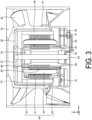
- FIG. 3 is a sectional view illustrating an example of the fan motor of the embodiment. FIG. 3 illustrates a cross section taken along a plane S1 of FIG. 1 .
- the motor 30 includes a stator 40, a magnet 38, the rotor yoke 39, and a substrate 50.
- the rotor yoke 39 of the embodiment is formed in a cup shape covering the stator 40 from the Z-axis positive direction side.
- the motor 30 further includes the bearings 91 and 92, the shaft 93, and a bearing liner 94.
- the rotor yoke 39 is an example of the rotor
- the bearing liner 94 is an example of the holding member.
- the stator 40 includes a stator core 41, insulators 42 and 43, and a coil 44.
- the stator core 41 is formed by stacking a plurality of plate-shaped metal members such as silicon steel sheets and soft magnetic steel sheets such as electromagnetic steel sheets in the Z-axis direction, for example.
- the insulators 42 and 43 are formed of an insulator such as a resin, for example.
- the insulators 42 and 43 are mounted to the stator core 41 from the positive direction side and the negative direction side in the Z-axis direction, respectively.
- the coil 44 is wound around the stator core 41 through the insulators 42 and 43. Note that the insulators 42 and 43 may be a coating with electrical insulation.
- the rotor yoke 39 is coupled to the upper end of the shaft 93 through a boss part 37, for example. In this case, the shaft 93 turns in conjunction with the rotor yoke 39.
- the magnet 38 is fixed to the inner periphery side of the rotor yoke 39.
- the magnet 38 and the rotor yoke 39, and the stator 40 are opposed to each other in the radial direction.
- the rotor yoke 39 is formed of a metal such as iron.
- the rotor yoke 39 need not be a cup-shaped integrated component, and a member coupled with the upper end of the shaft 93 and a member disposed at the outer periphery of the magnet 38 may be separate members.
- An electronic component for performing control and power feeding of the motor 30, and the like are disposed at the substrate 50.
- the substrate 50 is formed of a resin, for example.
- the electronic component includes an integrated circuit (IC), not illustrated in the drawing, that acquires detection results output from temperature sensors 61, 62 and 63 described later, and the like, for example.
- IC integrated circuit
- the bearings 91 and 92 are ball bearings, and support the shaft 93 in the radial direction, for example. Note that in the following description, the bearings 91 and 92 may be simply referred to as a bearing 90 for collective description, and may be referred to as the first bearing 91 and the second bearing 92 for differentiation.
- the bearing liner 94 supports the shaft 93 through the bearings 91 and 92.
- the bearing liner 94 is inserted in the Z-axis direction into the center portion of the stator 40 in the radial direction, for example.
- the bearing liner 94 is formed of a metal such as brass, for example.
- the motor 30 of the embodiment includes a temperature sensor to detect defects of the bearing 90.
- the motor 30 of the embodiment includes a plurality of the temperature sensors 61, 62 and 63.
- the plurality of the temperature sensors 61, 62 and 63 may be simply referred to as the temperature sensor 60 for collective description, and may be referred to as the first temperature sensor 61, the second temperature sensor 62, and the third temperature sensor 63 for differentiation.
- Each of the first temperature sensor 61, the second temperature sensor 62, and the third temperature sensor 63 outputs a detected temperature to a motor controlling IC described later and not illustrated in the drawing.
- FIG. 4 is a bottom view illustrating an example of a motor with an impeller attached to the motor of the embodiment.
- FIG. 5 is a bottom view illustrating an example of the fan motor of the embodiment.
- FIG. 6 is a perspective view illustrating an example of a motor with a rotor yoke detached from the motor in the embodiment.
- FIG. 7 is an enlarged sectional view illustrating an example of the fan motor of the embodiment.
- FIG. 7 is an enlarged view of a portion illustrated in a frame F1 in FIG. 3 .
- the first temperature sensor 61 is disposed farther toward the outer periphery side than the coil 44 in the radial direction, for example.
- the second temperature sensor 62 is disposed farther toward the inner periphery side than the coil 44 in the radial direction, for example.
- the first temperature sensor 61 is disposed at the substrate 50, for example. Specifically, at least the substrate 50 made of resin is interposed between the first temperature sensor 61 and the bearings 91 and 92. In addition, the distance between the first temperature sensor 61 and the coil 44 is smaller than the distance between the first temperature sensor 61 and the bearings 91 and 92.
- the second temperature sensor 62 is disposed at the bearing liner 94 in the embodiment.
- the second temperature sensor 62 is disposed at the Z-axis direction positive direction side of the bearing liner 94, e.g., at a position opposed to the first bearing 91 in the radial direction. More specifically, the second temperature sensor 62 is opposed to the first bearing 91 through the bearing liner 94 in the radial direction.
- the third temperature sensor 63 is further disposed inside the motor 30. Inside the motor 30, the third temperature sensor 63 is disposed in contact with any of the members.
- the third temperature sensor 63 is disposed at the Z-axis direction negative direction side and on the inner periphery side of the bearing liner 94 as illustrated in FIG. 5 . Note that in FIG. 5 , the first temperature sensor 61 and the second temperature sensor 62 are not visible. Note that the third temperature sensor 63 need not be disposed at the position described in the example, as long as the third temperature sensor 63 is disposed inside the motor.
- a shortest distance D1 between the first temperature sensor 61 and the closer one of the bearings 91 and 92 is greater than a shortest distance D2 between the second temperature sensor 62 and the closer one of the bearings 91 and 92, and is greater than a shortest distance D3 between the third temperature sensor 63 and the closer one of the bearings 91 and 92.
- a shortest distance D5 between the third temperature sensor 63 and the stator 40 is greater than a shortest distance D4 between the second temperature sensor 62 and the stator 40.
- the resin making up the substrate 50 formed with the first temperature sensor 61, and the bearing liner 94 made of metal disposed with the second temperature sensor 62 and the third temperature sensor 63 are different from each other in terms of thermal capacity and thermal conductivity.
- the thermal conductivity of the substrate 50 is smaller than 1 (W/mK), while the thermal conductivity of the bearing liner 94 is 10 (W/mK) or greater.
- the motor controlling IC disposed with the substrate 50 may include three temperature sensor terminals.
- the first temperature sensor 61, the second temperature sensor 62, and the third temperature sensor 63 are directly connected to the same motor controlling IC without interposing other members such as a resistor.
- the second temperature sensor 62 and the third temperature sensor 63 disposed separately from the substrate 50 are connected to the motor controlling IC through a wiring line 64 and a wiring line 65, respectively.
- the wiring line 64 is passed through a gap of teeth protruding in the radial direction in the stator core 41, and the wiring line 65 is passed through a hole 51 formed at the substrate 50 as illustrated in FIGS. 3 and 6 , for example.
- the temperature sensor 60 detects the temperature rise due to the friction, and thus the defect of the bearing 90 can be detected.
- the temperature sensor 60 also detects heat generated at the coil 44. As such, it may be difficult to identify whether a temperature rise is due to heat generated by the coil 44 or a defect of the bearing 90. For example, when a defect is caused at only one bearing, the temperature increases only at the periphery of the bearing, and therefore it is relatively easy to detect the defect. When defects are simultaneously caused at both the first bearing 91 and the second bearing 92, the temperature increases simultaneously at both the bearings 91 and 92, and therefore it is more difficult to detect the defects.
- the first temperature sensor 61 disposed at a position close to the coil 44 and the second temperature sensor 62 disposed at a position close to the bearing 91 or 92 are provided.
- a temperature change of the bearing 91 or 92 can be correctly detected on the basis of a detection result of the first temperature sensor 61 strongly influenced by the temperature change of the coil 44 and a detection result of the second temperature sensor 62 influenced by the temperature change of the bearing 91 or 92 in addition to the temperature change of the coil 44 even in the case where defects are simultaneously generated at the first bearing 91 and the second bearing 92, for example.
- a processing section of the motor controlling IC directly connected to the first temperature sensor 61, the second temperature sensor 62 and the third temperature sensor 63 outputs an output signal to the outside of the motor on the basis of the detection result of the first temperature sensor 61 and the detection result of the second temperature sensor 62, for example.
- the process of outputting the signal on the basis of the temperature change is described with reference to FIG. 8.
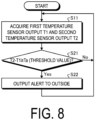
- FIG. 8 is a flowchart illustrating an example of an output process of the embodiment. As illustrated in FIG. 8 , the processing section not illustrated in the drawing acquires a detection result T1 output from the first temperature sensor 61 and a detection result T2 output from the second temperature sensor 62 (step S11).
- the processing section calculates a difference T2-T1 between the acquired detection result T2 and detection result T1. Then, whether the calculated difference T2-T1 is greater than threshold value Ta is determined (step S21).
- step S21, No When the difference T2-T1 is determined to be smaller than a threshold value Ta (step S21, No), the processing section returns to step S11, and continues the acquisition of the detection results T1 and T2. On the other hand, when the difference T2-T1 is determined to be greater than the threshold value Ta (step S21, Yes), the processing section outputs an alert to an external apparatus (step S22).
- the processing section may further acquire a detection result T3 output from the third temperature sensor 63 in addition to the detection results T1 and T2.
- the processing section may compare, with the threshold value Ta, the larger one of a difference T3-T1 between the detection results T1 and T3 and the difference T2-T1, for example.
- the motor 30 of the embodiment includes the shaft 93, a rotor yoke 39, the coil 44, the stator 40 opposed to the rotor yoke 39, and the bearing 91 supporting the shaft 93.
- the motor 30 includes the first temperature sensor 61 disposed farther toward the outer periphery side than the coil 44, and the second temperature sensor 62 disposed farther toward the inner periphery side than the coil 44.
- the embodiment is not limited to this.
- the number of the bearings for supporting the shaft 93 is not limited to two, and may be one, or three or more.
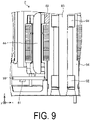
- FIG. 9 is an enlarged sectional view illustrating an example of a fan motor of the first modification example.
- a fan motor 2 of the first modification example includes the first temperature sensor 61 and the second temperature sensor 62, but does not include the third temperature sensor 63.
- the temperature sensor may be provided only at one of a portion near the first bearing 91 or a portion near the second bearing 92 in the Z-axis direction. In this case, the third temperature sensor 63 may be omitted.
- each temperature sensor is not limited to the position described in the embodiment.
- the first temperature sensor is disposed at the surface (lower side surface) of the substrate 50 on the negative direction side in the Z-axis direction, but the present invention is not limited to this, and the first temperature sensor may be disposed at the surface (upper side surface) on the opposite side of the substrate 50 as illustrated in FIG. 10.
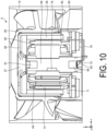
- FIG. 10 is a sectional view illustrating an example of a fan motor of a second modification example.
- FIG. 10 illustrates a cross section taken along a plane S2 of FIG. 1 .
- the second temperature sensor 72 is disposed at an intermediate position between the first bearing 91 and the second bearing 92 in the Z-axis direction.
- the temperature sensor when disposed separately from the substrate 50, the temperature sensor preferably transmits sensor information in a wireless manner in order to avoid complicated wiring.
- the second temperature sensor 72 may be disposed at the inner periphery side or the outer periphery side of the bearing liner 94.
- the second temperature sensor 72 may be disposed in contact with the bearing 90 as long as the second temperature sensor 72 is disposed at a position the temperature change of the bearing 90 can be determined.
- the third temperature sensor 73 be disposed at any of the members of the motor, and may be disposed at an end portion of the bearing 90 in the axis direction and the like as illustrated in FIG. 10 , for example. Also in this case, the third temperature sensor 73 is connected to the motor controlling IC not illustrated in the drawing through a wiring line 75 passing through the hole 51 of the substrate 50, for example.
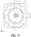
- FIG. 11 is a bottom view illustrating an example of a fan motor of a third modification example.
- the second temperature sensor 82 and the third temperature sensor 83 disposed separately from each other in the Z-axis direction may be disposed at overlapping positions in plan view.
- the first temperature sensor 61, the second temperature sensor 82 and the third temperature sensor 83 may be disposed in substantially the same direction in the circumferential direction.
- the processing section not illustrated in the drawing acquires the detection results T1 and T2 and outputs an alert based on the calculated result of the difference T2-T1, but the embodiment is not limited to this.
- the processing section may output the difference T2-T1 as is without determining whether to output the alert.
- FIG. 12 is a flowchart illustrating an example of an output process of a fourth modification example.
- the processing section of the fourth modification example not illustrated in the drawing calculates the difference T2-T1 between the acquired detection result T2 and detection result T1. Then, the processing section outputs the calculated difference T2-T1 to an external apparatus as is (step S31).
- the processing section need not store the threshold value Ta, and thus the configuration of the motor can be simplified.
- the motor 30 may output the detection results T1 and T2 as is to the outside without calculating the difference T2-T1.
- the processing section for calculating the difference T2-T1 of the detection result need not be disposed at the motor, and thus the configuration of the motor can be further simplified.
- the embodiment is not limited to this.
- the first bearing 91 and the second bearing 92 may be held at respective holding members.
- the plurality of holding members be composed of the same material and in contact with each other.
- the holding member may be formed of iron or another material other than brass as long as the holding member is composed of a material with high thermal conductivity.
- another resin component other than the substrate 50 may be interposed between the first temperature sensor 61 and the bearing 91 or 92.
- the second temperature sensor 62 and the third temperature sensor 73 may be in direct contact with the bearing 91.
- the part the motor 30 is mounted is not limited to the fan motor 1, and the motor 30 may be mounted at other external apparatuses. Further, the temperature sensor described in the embodiment and the modification examples may be mounted at other rotating electrical machinery such as a generator instead of a motor.
Abstract
Description
- The present invention relates to a motor and a fan motor.
- A technique of detecting defects of a bearing by detecting variation of frictional heat generated from the bearing by using a temperature sensor in rotating electrical machinery such as a motor and a generator is known.
-
- [PTL 1]
JP 2015-231295 A - [PTL 2]
JP 2020-133889 A - In rotating electrical machinery, when a defect is caused at a bearing under the influence of heat generated from a coil, it is difficult to correctly detect the influence of the heat generation caused by the defect of the bearing. As such, a motor capable of more correctly detecting the temperature change of a bearing is desired.
- An object of an aspect is to provide a motor and a fan motor capable of correctly detecting the temperature change of a bearing.
- According to an aspect, a motor includes a shaft, a rotor, a stator including a coil and opposed to the rotor, and a bearing configured to support the shaft. In addition, the motor further includes a first temperature sensor disposed farther toward an outer periphery side than the coil, and a second temperature sensor disposed farther toward an inner periphery side than the coil.
- According to the aspect, the temperature change of the bearing can be more correctly detected.
-
- [
FIG. 1] FIG. 1 is a diagram illustrating an example of a fan motor of an embodiment. - [
FIG. 2] FIG. 2 is an exploded perspective view illustrating an example of the fan motor of the embodiment. - [
FIG. 3] FIG. 3 is a sectional view illustrating an example of the fan motor of the embodiment. - [
FIG. 4] FIG. 4 is a bottom view illustrating an example of a motor with an impeller attached to the motor of the embodiment. - [
FIG. 5] FIG. 5 is a bottom view illustrating an example of the fan motor of the embodiment. - [
FIG. 6] FIG. 6 is a perspective view illustrating an example of a motor with a rotor yoke detached from the motor in the embodiment. - [
FIG. 7] FIG. 7 is an enlarged sectional view illustrating an example of a fan motor of the embodiment. - [
FIG. 8] FIG. 8 is a flowchart illustrating an example of an output process of the embodiment. - [
FIG. 9] FIG. 9 is an enlarged sectional view illustrating an example of a fan motor of a first modification example. - [
FIG. 10] FIG. 10 is a sectional view illustrating an example of a fan motor of a second modification example. - [
FIG. 11] FIG. 11 is a bottom view illustrating an example of a fan motor of a third modification example. - [
FIG. 12] FIG. 12 is a flowchart illustrating an example of an output process of a fourth modification example. - An embodiment of a motor and a fan motor disclosed in this application is described below with reference to the drawings. Note that in the drawings, the dimensional relationship of elements and the ratio of the elements may not be drawn to scale. The dimensional relationship and the ratio may be different among the drawings. In the drawings, an XYZ coordinate system with the axis direction of a
motor 30 described later set to the Z axis positive direction may be used for the sake of clarity of description. - First, a fan motor of the embodiment is described with reference to
FIGS. 1 and2 .FIG. 1 is a diagram illustrating an example of a fan motor of the embodiment.FIG. 2 is an exploded perspective view illustrating an example of the fan motor. As illustrated inFIGS. 1 and2 , afan motor 1 of the embodiment includes ahousing 10, animpeller 20, and themotor 30. Thefan motor 1 is used as a fan motor for a server, for example. - The
housing 10 and theimpeller 20 are formed of a metal such as resin or aluminum, for example. Theimpeller 20 and themotor 30 are housed into thehousing 10 from the Z-axis positive direction side. Note that inFIG. 1 , themotor 30 is covered with theimpeller 20 and is not visible. - The
housing 10 includes abottom surface 11, a plurality ofstationary blades 12, and aside wall 19. Theside wall 19 is formed approximately parallel to the Z-axis direction. The plurality ofstationary blades 12 are located on the lower side in the axial direction, and extend in the radial direction with thebottom surface 11 as the center. - As illustrated in
FIG. 2 , theimpeller 20 includes ahub 21 and a plurality ofrotor blades 22. As illustrated inFIG. 2 , theimpeller 20 is mounted at themotor 30 from the Z-axis direction positive direction side, and turns in conjunction with themotor 30 with the Z axis as the rotation axis. - The
motor 30 is, for example, an outer rotor type motor. As illustrated inFIG. 3 , arotor yoke 39 of themotor 30 turns ashaft 93 supported bybearings FIG. 3 is a sectional view illustrating an example of the fan motor of the embodiment.FIG. 3 illustrates a cross section taken along a plane S1 ofFIG. 1 . - As illustrated in
FIG. 3 , themotor 30 includes astator 40, amagnet 38, therotor yoke 39, and asubstrate 50. As illustrated inFIG. 3 , therotor yoke 39 of the embodiment is formed in a cup shape covering thestator 40 from the Z-axis positive direction side. In addition, themotor 30 further includes thebearings shaft 93, and abearing liner 94. Note that therotor yoke 39 is an example of the rotor, and thebearing liner 94 is an example of the holding member. - The
stator 40 includes astator core 41,insulators coil 44. Thestator core 41 is formed by stacking a plurality of plate-shaped metal members such as silicon steel sheets and soft magnetic steel sheets such as electromagnetic steel sheets in the Z-axis direction, for example. Theinsulators insulators stator core 41 from the positive direction side and the negative direction side in the Z-axis direction, respectively. Thecoil 44 is wound around thestator core 41 through theinsulators insulators - The
rotor yoke 39 is coupled to the upper end of theshaft 93 through aboss part 37, for example. In this case, theshaft 93 turns in conjunction with therotor yoke 39. Themagnet 38 is fixed to the inner periphery side of therotor yoke 39. Themagnet 38 and therotor yoke 39, and thestator 40 are opposed to each other in the radial direction. Therotor yoke 39 is formed of a metal such as iron. In addition, therotor yoke 39 need not be a cup-shaped integrated component, and a member coupled with the upper end of theshaft 93 and a member disposed at the outer periphery of themagnet 38 may be separate members. - An electronic component, not illustrated in the drawing, for performing control and power feeding of the
motor 30, and the like are disposed at thesubstrate 50. Thesubstrate 50 is formed of a resin, for example. The electronic component includes an integrated circuit (IC), not illustrated in the drawing, that acquires detection results output fromtemperature sensors - The
bearings shaft 93 in the radial direction, for example. Note that in the following description, thebearings first bearing 91 and thesecond bearing 92 for differentiation. - The
bearing liner 94 supports theshaft 93 through thebearings bearing liner 94 is inserted in the Z-axis direction into the center portion of thestator 40 in the radial direction, for example. Thebearing liner 94 is formed of a metal such as brass, for example. - The
motor 30 of the embodiment includes a temperature sensor to detect defects of the bearing 90. As illustrated inFIG. 3 , themotor 30 of the embodiment includes a plurality of thetemperature sensors temperature sensors first temperature sensor 61, thesecond temperature sensor 62, and thethird temperature sensor 63 for differentiation. Each of thefirst temperature sensor 61, thesecond temperature sensor 62, and thethird temperature sensor 63 outputs a detected temperature to a motor controlling IC described later and not illustrated in the drawing. - Positional relationships of the
temperature sensors FIGS. 4 ,5 ,6 , and7 .FIG. 4 is a bottom view illustrating an example of a motor with an impeller attached to the motor of the embodiment.FIG. 5 is a bottom view illustrating an example of the fan motor of the embodiment.FIG. 6 is a perspective view illustrating an example of a motor with a rotor yoke detached from the motor in the embodiment.FIG. 7 is an enlarged sectional view illustrating an example of the fan motor of the embodiment.FIG. 7 is an enlarged view of a portion illustrated in a frame F1 inFIG. 3 . - As illustrated in
FIGS. 4 and7 , thefirst temperature sensor 61 is disposed farther toward the outer periphery side than thecoil 44 in the radial direction, for example. On the other hand, thesecond temperature sensor 62 is disposed farther toward the inner periphery side than thecoil 44 in the radial direction, for example. - The
first temperature sensor 61 is disposed at thesubstrate 50, for example. Specifically, at least thesubstrate 50 made of resin is interposed between thefirst temperature sensor 61 and thebearings first temperature sensor 61 and thecoil 44 is smaller than the distance between thefirst temperature sensor 61 and thebearings - In addition, the
second temperature sensor 62 is disposed at thebearing liner 94 in the embodiment. To be more specific, thesecond temperature sensor 62 is disposed at the Z-axis direction positive direction side of thebearing liner 94, e.g., at a position opposed to thefirst bearing 91 in the radial direction. More specifically, thesecond temperature sensor 62 is opposed to thefirst bearing 91 through thebearing liner 94 in the radial direction. - In addition, in the embodiment, the
third temperature sensor 63 is further disposed inside themotor 30. Inside themotor 30, thethird temperature sensor 63 is disposed in contact with any of the members. For example, thethird temperature sensor 63 is disposed at the Z-axis direction negative direction side and on the inner periphery side of thebearing liner 94 as illustrated inFIG. 5 . Note that inFIG. 5 , thefirst temperature sensor 61 and thesecond temperature sensor 62 are not visible. Note that thethird temperature sensor 63 need not be disposed at the position described in the example, as long as thethird temperature sensor 63 is disposed inside the motor. - As illustrated in
FIG. 7 , in the embodiment, a shortest distance D1 between thefirst temperature sensor 61 and the closer one of thebearings second temperature sensor 62 and the closer one of thebearings third temperature sensor 63 and the closer one of thebearings FIG. 7 , a shortest distance D5 between thethird temperature sensor 63 and thestator 40 is greater than a shortest distance D4 between thesecond temperature sensor 62 and thestator 40. - In addition, in the embodiment, the resin making up the
substrate 50 formed with thefirst temperature sensor 61, and thebearing liner 94 made of metal disposed with thesecond temperature sensor 62 and thethird temperature sensor 63 are different from each other in terms of thermal capacity and thermal conductivity. For example, the thermal conductivity of thesubstrate 50 is smaller than 1 (W/mK), while the thermal conductivity of thebearing liner 94 is 10 (W/mK) or greater. - In addition, in the embodiment, the motor controlling IC, not illustrated in the drawing, disposed with the
substrate 50 may include three temperature sensor terminals. In this case, thefirst temperature sensor 61, thesecond temperature sensor 62, and thethird temperature sensor 63 are directly connected to the same motor controlling IC without interposing other members such as a resistor. - For example, the
second temperature sensor 62 and thethird temperature sensor 63 disposed separately from thesubstrate 50 are connected to the motor controlling IC through awiring line 64 and awiring line 65, respectively. Note that thewiring line 64 is passed through a gap of teeth protruding in the radial direction in thestator core 41, and thewiring line 65 is passed through ahole 51 formed at thesubstrate 50 as illustrated inFIGS. 3 and6 , for example. - In the embodiment, when a defect occurs at the bearing 90, friction is more likely to occur due to degradation of grease and/or leakage of oil at portions between the
shaft 93 and the bearing 90, between the bearing 90 and thebearing liner 94, inside the bearing 90 and the like. In this case, the temperature sensor 60 detects the temperature rise due to the friction, and thus the defect of the bearing 90 can be detected. - On the other hand, the temperature sensor 60 also detects heat generated at the
coil 44. As such, it may be difficult to identify whether a temperature rise is due to heat generated by thecoil 44 or a defect of the bearing 90. For example, when a defect is caused at only one bearing, the temperature increases only at the periphery of the bearing, and therefore it is relatively easy to detect the defect. When defects are simultaneously caused at both thefirst bearing 91 and thesecond bearing 92, the temperature increases simultaneously at both thebearings - In view of this, in the embodiment, the
first temperature sensor 61 disposed at a position close to thecoil 44 and thesecond temperature sensor 62 disposed at a position close to thebearing bearing first temperature sensor 61 strongly influenced by the temperature change of thecoil 44 and a detection result of thesecond temperature sensor 62 influenced by the temperature change of thebearing coil 44 even in the case where defects are simultaneously generated at thefirst bearing 91 and thesecond bearing 92, for example. - In the embodiment, a processing section of the motor controlling IC directly connected to the
first temperature sensor 61, thesecond temperature sensor 62 and thethird temperature sensor 63 outputs an output signal to the outside of the motor on the basis of the detection result of thefirst temperature sensor 61 and the detection result of thesecond temperature sensor 62, for example. The process of outputting the signal on the basis of the temperature change is described with reference toFIG. 8. FIG. 8 is a flowchart illustrating an example of an output process of the embodiment. As illustrated inFIG. 8 , the processing section not illustrated in the drawing acquires a detection result T1 output from thefirst temperature sensor 61 and a detection result T2 output from the second temperature sensor 62 (step S11). - Next, the processing section calculates a difference T2-T1 between the acquired detection result T2 and detection result T1. Then, whether the calculated difference T2-T1 is greater than threshold value Ta is determined (step S21).
- When the difference T2-T1 is determined to be smaller than a threshold value Ta (step S21, No), the processing section returns to step S11, and continues the acquisition of the detection results T1 and T2. On the other hand, when the difference T2-T1 is determined to be greater than the threshold value Ta (step S21, Yes), the processing section outputs an alert to an external apparatus (step S22).
- Note that the processing section may further acquire a detection result T3 output from the
third temperature sensor 63 in addition to the detection results T1 and T2. In this case, the processing section may compare, with the threshold value Ta, the larger one of a difference T3-T1 between the detection results T1 and T3 and the difference T2-T1, for example. - As described above, the
motor 30 of the embodiment includes theshaft 93, arotor yoke 39, thecoil 44, thestator 40 opposed to therotor yoke 39, and thebearing 91 supporting theshaft 93. In addition, themotor 30 includes thefirst temperature sensor 61 disposed farther toward the outer periphery side than thecoil 44, and thesecond temperature sensor 62 disposed farther toward the inner periphery side than thecoil 44. With this configuration, the temperature change of the bearing can be more correctly detected by detecting the temperature inside the motor by using thefirst temperature sensor 61 less influenced by the temperature change of thebearing - While the configuration of the embodiment is described above, the embodiment is not limited to this. For example, the number of the bearings for supporting the
shaft 93 is not limited to two, and may be one, or three or more. - In addition, while the three
temperature sensors third temperature sensor 63 is not provided, i.e., only two temperature sensors are provided as illustrated inFIG. 9. FIG. 9 is an enlarged sectional view illustrating an example of a fan motor of the first modification example. As illustrated inFIG. 9 , afan motor 2 of the first modification example includes thefirst temperature sensor 61 and thesecond temperature sensor 62, but does not include thethird temperature sensor 63. - For example, when the thermal conductivity of the
bearing liner 94 is sufficiently high, the temperature sensor may be provided only at one of a portion near thefirst bearing 91 or a portion near thesecond bearing 92 in the Z-axis direction. In this case, thethird temperature sensor 63 may be omitted. - In addition, the position disposed with each temperature sensor is not limited to the position described in the embodiment. For example, in the embodiment, the first temperature sensor is disposed at the surface (lower side surface) of the
substrate 50 on the negative direction side in the Z-axis direction, but the present invention is not limited to this, and the first temperature sensor may be disposed at the surface (upper side surface) on the opposite side of thesubstrate 50 as illustrated inFIG. 10. FIG. 10 is a sectional view illustrating an example of a fan motor of a second modification example.FIG. 10 illustrates a cross section taken along a plane S2 ofFIG. 1 . - In addition, as illustrated in
FIG. 10 , in afan motor 3 of the second modification example, thesecond temperature sensor 72 is disposed at an intermediate position between thefirst bearing 91 and thesecond bearing 92 in the Z-axis direction. Note that when disposed separately from thesubstrate 50, the temperature sensor preferably transmits sensor information in a wireless manner in order to avoid complicated wiring. In this manner, thesecond temperature sensor 72 may be disposed at the inner periphery side or the outer periphery side of thebearing liner 94. In addition, thesecond temperature sensor 72 may be disposed in contact with the bearing 90 as long as thesecond temperature sensor 72 is disposed at a position the temperature change of the bearing 90 can be determined. - In addition, it suffices that the
third temperature sensor 73 be disposed at any of the members of the motor, and may be disposed at an end portion of the bearing 90 in the axis direction and the like as illustrated inFIG. 10 , for example. Also in this case, thethird temperature sensor 73 is connected to the motor controlling IC not illustrated in the drawing through awiring line 75 passing through thehole 51 of thesubstrate 50, for example. - In addition, the positional relationship of each temperature sensor in the circumferential direction is also not limited to the relationship described in the embodiment.
FIG. 11 is a bottom view illustrating an example of a fan motor of a third modification example. As illustrated inFIG. 11 , thesecond temperature sensor 82 and thethird temperature sensor 83 disposed separately from each other in the Z-axis direction may be disposed at overlapping positions in plan view. In addition, thefirst temperature sensor 61, thesecond temperature sensor 82 and thethird temperature sensor 83 may be disposed in substantially the same direction in the circumferential direction. - In addition, in the embodiment, the processing section not illustrated in the drawing acquires the detection results T1 and T2 and outputs an alert based on the calculated result of the difference T2-T1, but the embodiment is not limited to this. For example, the processing section may output the difference T2-T1 as is without determining whether to output the alert.
-
FIG. 12 is a flowchart illustrating an example of an output process of a fourth modification example. As illustrated inFIG. 12 , when acquiring the detection result T1 output from thefirst temperature sensor 61 and the detection result T2 output from the second temperature sensor 62 (step S11), the processing section of the fourth modification example not illustrated in the drawing calculates the difference T2-T1 between the acquired detection result T2 and detection result T1. Then, the processing section outputs the calculated difference T2-T1 to an external apparatus as is (step S31). - With this configuration, the processing section need not store the threshold value Ta, and thus the configuration of the motor can be simplified.
- In addition, the
motor 30 may output the detection results T1 and T2 as is to the outside without calculating the difference T2-T1. With this configuration, the processing section for calculating the difference T2-T1 of the detection result need not be disposed at the motor, and thus the configuration of the motor can be further simplified. - In addition, while the two
bearings same bearing liner 94 in the embodiment, the embodiment is not limited to this. For example, thefirst bearing 91 and thesecond bearing 92 may be held at respective holding members. Also in this case, it is preferable that the plurality of holding members be composed of the same material and in contact with each other. In addition, the holding member may be formed of iron or another material other than brass as long as the holding member is composed of a material with high thermal conductivity. - In addition, another resin component other than the
substrate 50 may be interposed between thefirst temperature sensor 61 and thebearing - In addition, the
second temperature sensor 62 and thethird temperature sensor 73 may be in direct contact with thebearing 91. - Note that the part the
motor 30 is mounted is not limited to thefan motor 1, and themotor 30 may be mounted at other external apparatuses. Further, the temperature sensor described in the embodiment and the modification examples may be mounted at other rotating electrical machinery such as a generator instead of a motor. - Embodiments and modification examples of the present invention have been described, but the present invention is not limited to the embodiments and modification examples, and various modifications are possible without departing from the spirit of the present invention. Various modifications within a scope not departing from the gist are included in the technical scope of the present invention, and this is obvious to a person having skill in the art from the description of the claims.
-
- 1, 2, 3 Fan motor
- 10 Housing
- 11 Bottom surface
- 12 Stator blade
- 19 Side wall
- 20 Impeller
- 21 Hub
- 22 Rotor blade
- 30 Motor
- 37 Boss part
- 38 Magnet
- 39 Rotor yoke
- 40 Stator
- 41 Stator core
- 42, 43 Insulator
- 44 Coil
- 50 Substrate
- 61, 62, 63, 72, 73, 81, 82, 83 Temperature sensor
- 64, 65, 75 Wiring line
- 91, 92 Bearing
- 93 Shaft
- 94 Bearing liner
Claims (10)
- A motor (30) comprising:a shaft (93);a rotor (39);a stator (40) including a coil (44) and opposed to the rotor (39);a bearing (90) configured to support the shaft (93);a first temperature sensor (61) disposed farther toward an outer periphery side than the coil (44); anda second temperature sensor (62) disposed farther toward an inner periphery side than the coil (44).
- The motor (30) according to claim 1, further comprising:a holding member (94) configured to hold the bearing (90), whereinthe second temperature sensor (62) is disposed at the holding member (94).
- The motor (30) according to claim 1 or 2, wherein
a shortest distance between the first temperature sensor (61) and the bearing (90) is greater than a shortest distance between the second temperature sensor (62) and the bearing (90). - The motor (30) according to any one of claims 1 to 3, wherein
a thermal capacity of a member disposed with the first temperature sensor (61) and a thermal capacity of a member disposed with the second temperature sensor (62) are different from each other. - The motor (30) according to any one of claims 1 to 4, whereina thermal conductivity of a member disposed with the first temperature sensor (61) is smaller than 1 (W/mK); anda thermal conductivity of a member disposed with the second temperature sensor (62) is 10 (W/mK) or greater.
- The motor (30) according to any one of claims 1 to 5, further comprising:a third temperature sensor (63) disposed inside the motor (30), whereinthe first temperature sensor (61), the second temperature sensor (62) and the third temperature sensor (63) are directly connected to a motor controlling IC.
- The motor (30) according to claim 6, wherein
a shortest distance between the third temperature sensor (63) and the stator (40) is greater than a shortest distance between the second temperature sensor (62) and the stator (40). - The motor (30) according to any one of claims 1 to 7, wherein
an output signal is output to outside of the motor (30), based on a detection result of the first temperature sensor (61) and a detection result of the second temperature sensor (62). - The motor (30) according to any one of claims 1 to 8, wherein
a difference between a detection result of the first temperature sensor (61) and a detection result of the second temperature sensor (62) is output to outside of the motor (30). - A fan motor (1) comprising:an impeller (20); andthe motor (30) according to any one of claims 1 to 9.
Applications Claiming Priority (1)
| Application Number | Priority Date | Filing Date | Title |
|---|---|---|---|
| JP2021145727A JP2023038818A (en) | 2021-09-07 | 2021-09-07 | motor and fan motor |
Publications (1)
| Publication Number | Publication Date |
|---|---|
| EP4145687A1 true EP4145687A1 (en) | 2023-03-08 |
Family
ID=83191844
Family Applications (1)
| Application Number | Title | Priority Date | Filing Date |
|---|---|---|---|
| EP22193605.7A Pending EP4145687A1 (en) | 2021-09-07 | 2022-09-02 | Motor and fan motor |
Country Status (4)
| Country | Link |
|---|---|
| US (1) | US11962202B2 (en) |
| EP (1) | EP4145687A1 (en) |
| JP (1) | JP2023038818A (en) |
| CN (1) | CN115776195A (en) |
Citations (4)
| Publication number | Priority date | Publication date | Assignee | Title |
|---|---|---|---|---|
| DE10049506A1 (en) * | 1999-10-12 | 2001-04-19 | Csi Technology Inc | Integrated electric motor monitor records all parameters gives early fault diagnosis |
| US6617713B1 (en) * | 2002-10-07 | 2003-09-09 | Hsu-Chuan Li | Stagnant rotating prevention and safety control device for a main shaft |
| DE10305368A1 (en) * | 2003-02-10 | 2004-08-19 | Siemens Ag | Electrical machine with temperature monitoring especially for large electrical machines, uses thermal radiation sensors for contactless detection of radiant heat |
| JP2015231295A (en) * | 2014-06-05 | 2015-12-21 | 株式会社日立製作所 | Bearing failure sign diagnosis device, bearing failure sign diagnosis system, and bearing failure sign diagnosis method |
Family Cites Families (1)
| Publication number | Priority date | Publication date | Assignee | Title |
|---|---|---|---|---|
| JP2020133889A (en) | 2019-02-12 | 2020-08-31 | Ntn株式会社 | Bearing device and spindle device |
-
2021
- 2021-09-07 JP JP2021145727A patent/JP2023038818A/en active Pending
-
2022
- 2022-07-06 CN CN202210796537.8A patent/CN115776195A/en active Pending
- 2022-07-14 US US17/812,528 patent/US11962202B2/en active Active
- 2022-09-02 EP EP22193605.7A patent/EP4145687A1/en active Pending
Patent Citations (4)
| Publication number | Priority date | Publication date | Assignee | Title |
|---|---|---|---|---|
| DE10049506A1 (en) * | 1999-10-12 | 2001-04-19 | Csi Technology Inc | Integrated electric motor monitor records all parameters gives early fault diagnosis |
| US6617713B1 (en) * | 2002-10-07 | 2003-09-09 | Hsu-Chuan Li | Stagnant rotating prevention and safety control device for a main shaft |
| DE10305368A1 (en) * | 2003-02-10 | 2004-08-19 | Siemens Ag | Electrical machine with temperature monitoring especially for large electrical machines, uses thermal radiation sensors for contactless detection of radiant heat |
| JP2015231295A (en) * | 2014-06-05 | 2015-12-21 | 株式会社日立製作所 | Bearing failure sign diagnosis device, bearing failure sign diagnosis system, and bearing failure sign diagnosis method |
Also Published As
| Publication number | Publication date |
|---|---|
| CN115776195A (en) | 2023-03-10 |
| JP2023038818A (en) | 2023-03-17 |
| US20230073481A1 (en) | 2023-03-09 |
| US11962202B2 (en) | 2024-04-16 |
Similar Documents
| Publication | Publication Date | Title |
|---|---|---|
| US9653960B2 (en) | Motor and blower | |
| JP7028548B2 (en) | Sensor assembly and motors including it | |
| US9812932B2 (en) | Motor | |
| US7642681B2 (en) | Rotary electric machine equipped with one or more magnetic sensors | |
| JP6806087B2 (en) | Multicopter | |
| CN205078479U (en) | Motor and ceiling fan for ceiling fan | |
| US20180026496A1 (en) | Motor having function of generating and feeding electric power at coil end portion | |
| US20150093271A1 (en) | Brushless motor and fan using the motor | |
| US8823225B2 (en) | Rotating electrical machine | |
| CN107110666B (en) | Rotation angle detecting device | |
| US20090108716A1 (en) | Brushless motor and cooling fan | |
| JPWO2013038528A1 (en) | Rotating electric machine | |
| JP2015027200A (en) | Rotation angle detection device, assembly method of rotation angle detection device, and rotary electric machine | |
| EP4145687A1 (en) | Motor and fan motor | |
| US11204261B2 (en) | Rotational position detection device | |
| US11552533B2 (en) | Stator assembly, motor, and fan motor | |
| JPH1118361A (en) | Motor with built-in controller | |
| JP5962265B2 (en) | Electric motor and transfer device | |
| JP5962264B2 (en) | Electric motor and transfer device | |
| BR102012000841A2 (en) | ELECTRICAL MACHINE AND METHOD FOR OPERATING AN ELECTRICAL MACHINE | |
| US20230032445A1 (en) | Rotating electric machine system | |
| CN210509968U (en) | Magnetic suspension bearing system and tool with same | |
| US20190028000A1 (en) | Device for detecting position of rotor, and motor comprising same | |
| JP2020145780A (en) | Motor unit and fan | |
| CN114814415A (en) | Reluctance type rolling bearing power generation detection system and power generation detection device |
Legal Events
| Date | Code | Title | Description |
|---|---|---|---|
| PUAI | Public reference made under article 153(3) epc to a published international application that has entered the european phase |
Free format text: ORIGINAL CODE: 0009012 |
|
| STAA | Information on the status of an ep patent application or granted ep patent |
Free format text: STATUS: THE APPLICATION HAS BEEN PUBLISHED |
|
| AK | Designated contracting states |
Kind code of ref document: A1 Designated state(s): AL AT BE BG CH CY CZ DE DK EE ES FI FR GB GR HR HU IE IS IT LI LT LU LV MC MK MT NL NO PL PT RO RS SE SI SK SM TR |
|
| STAA | Information on the status of an ep patent application or granted ep patent |
Free format text: STATUS: REQUEST FOR EXAMINATION WAS MADE |
|
| 17P | Request for examination filed |
Effective date: 20230905 |
|
| RBV | Designated contracting states (corrected) |
Designated state(s): AL AT BE BG CH CY CZ DE DK EE ES FI FR GB GR HR HU IE IS IT LI LT LU LV MC MK MT NL NO PL PT RO RS SE SI SK SM TR |