EP4145650A1 - Lifetime prediction of a gas filling of an electrical switchgear - Google Patents
Lifetime prediction of a gas filling of an electrical switchgear Download PDFInfo
- Publication number
- EP4145650A1 EP4145650A1 EP22192301.4A EP22192301A EP4145650A1 EP 4145650 A1 EP4145650 A1 EP 4145650A1 EP 22192301 A EP22192301 A EP 22192301A EP 4145650 A1 EP4145650 A1 EP 4145650A1
- Authority
- EP
- European Patent Office
- Prior art keywords
- pressure value
- gas filling
- time
- pressure
- point
- Prior art date
- Legal status (The legal status is an assumption and is not a legal conclusion. Google has not performed a legal analysis and makes no representation as to the accuracy of the status listed.)
- Granted
Links
Images

Classifications
-
- H—ELECTRICITY
- H01—ELECTRIC ELEMENTS
- H01H—ELECTRIC SWITCHES; RELAYS; SELECTORS; EMERGENCY PROTECTIVE DEVICES
- H01H33/00—High-tension or heavy-current switches with arc-extinguishing or arc-preventing means
- H01H33/02—Details
- H01H33/53—Cases; Reservoirs, tanks, piping or valves, for arc-extinguishing fluid; Accessories therefor, e.g. safety arrangements, pressure relief devices
- H01H33/56—Gas reservoirs
- H01H33/563—Gas reservoirs comprising means for monitoring the density of the insulating gas
-
- G—PHYSICS
- G01—MEASURING; TESTING
- G01R—MEASURING ELECTRIC VARIABLES; MEASURING MAGNETIC VARIABLES
- G01R31/00—Arrangements for testing electric properties; Arrangements for locating electric faults; Arrangements for electrical testing characterised by what is being tested not provided for elsewhere
- G01R31/12—Testing dielectric strength or breakdown voltage ; Testing or monitoring effectiveness or level of insulation, e.g. of a cable or of an apparatus, for example using partial discharge measurements; Electrostatic testing
- G01R31/1227—Testing dielectric strength or breakdown voltage ; Testing or monitoring effectiveness or level of insulation, e.g. of a cable or of an apparatus, for example using partial discharge measurements; Electrostatic testing of components, parts or materials
- G01R31/1254—Testing dielectric strength or breakdown voltage ; Testing or monitoring effectiveness or level of insulation, e.g. of a cable or of an apparatus, for example using partial discharge measurements; Electrostatic testing of components, parts or materials of gas-insulated power appliances or vacuum gaps
-
- G—PHYSICS
- G01—MEASURING; TESTING
- G01L—MEASURING FORCE, STRESS, TORQUE, WORK, MECHANICAL POWER, MECHANICAL EFFICIENCY, OR FLUID PRESSURE
- G01L13/00—Devices or apparatus for measuring differences of two or more fluid pressure values
- G01L13/02—Devices or apparatus for measuring differences of two or more fluid pressure values using elastically-deformable members or pistons as sensing elements
- G01L13/025—Devices or apparatus for measuring differences of two or more fluid pressure values using elastically-deformable members or pistons as sensing elements using diaphragms
-
- G—PHYSICS
- G01—MEASURING; TESTING
- G01L—MEASURING FORCE, STRESS, TORQUE, WORK, MECHANICAL POWER, MECHANICAL EFFICIENCY, OR FLUID PRESSURE
- G01L9/00—Measuring steady of quasi-steady pressure of fluid or fluent solid material by electric or magnetic pressure-sensitive elements; Transmitting or indicating the displacement of mechanical pressure-sensitive elements, used to measure the steady or quasi-steady pressure of a fluid or fluent solid material, by electric or magnetic means
- G01L9/0041—Transmitting or indicating the displacement of flexible diaphragms
- G01L9/0072—Transmitting or indicating the displacement of flexible diaphragms using variations in capacitance
-
- H—ELECTRICITY
- H02—GENERATION; CONVERSION OR DISTRIBUTION OF ELECTRIC POWER
- H02B—BOARDS, SUBSTATIONS OR SWITCHING ARRANGEMENTS FOR THE SUPPLY OR DISTRIBUTION OF ELECTRIC POWER
- H02B13/00—Arrangement of switchgear in which switches are enclosed in, or structurally associated with, a casing, e.g. cubicle
- H02B13/02—Arrangement of switchgear in which switches are enclosed in, or structurally associated with, a casing, e.g. cubicle with metal casing
- H02B13/035—Gas-insulated switchgear
- H02B13/065—Means for detecting or reacting to mechanical or electrical defects
- H02B13/0655—Means for detecting or reacting to mechanical or electrical defects through monitoring changes of gas properties
Definitions
- the invention relates to a method of predicting a lifetime of a gas filling of an electrical switchgear.
- the system of an electrical switchgear can be filled with an insulating gas forming the gas filling of the electrical switchgear.
- the insulating gas may consist of or comprise Sulfur hexafluoride (SF6).
- SF6 Sulfur hexafluoride
- the gas filling may leak from the system so that the insulating function may decrease.
- a minimum pressure value of the gas filling can be defined. Once the pressure of the gas filling drops below this minimum pressure value, operation of the electrical switchgear can get dangerous. That is why it is advisable to stop the operation of the electrical switchgear in such a situation. Unfortunately, such a situation may occur unexpectedly and lead to an unwanted downtime of the electrical switchgear.
- an object of the invention is the provision of a method of predicting a lifetime of a gas filling of an electrical switchgear. In particular, an unexpected downtime of an electrical switchgear shall be avoided.
- the object of the invention is solved by a method of predicting a lifetime of a gas filling of an electrical switchgear, which comprises the steps of
- p 1 is the first pressure value
- p 2 is the second pressure value
- ⁇ p is the pressure difference between the second pressure value p 2 and the first pressure value p 1
- t 1 is the first point in time and t 2 is the second point in time
- ⁇ t is the time difference between the second point in time t 2 and the first point in time t 1
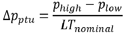
- ⁇ p ptu is the nominal pressure drop per time unit (for example per year)
- LT nominal is the nominal lifetime of the gas filling
- piow is the minimum pressure value of the
- the minimum pressure value piow of the gas filling ensures a minimum level of insulation. Below that value, operation of the electrical switchgear may get dangerous.
- the maximum pressure value p high of the gas filling normally is the initial pressure when the system is filled.
- the nominal lifetime LT nominal of the gas filling is the expected lifetime of the gas filling, e.g. 30 years.
- the nominal pressure drop per time unit ⁇ p ptu corresponds to this nominal lifetime LT nominal and the difference between the maximum pressure value p high and the minimum pressure value p low .
- p 1 is the first pressure value
- p 2 is the second pressure value
- p low is the minimum pressure value of the gas filling
- ⁇ p is the pressure difference between the second pressure value p 2 and the first pressure value p 1
- t 1 is the first point in time
- t 2 is the second point in time
- ⁇ t is the time difference between the second point in time t 2 and the first point in time t 1 .
- the pressures p 1 and p 2 may be determined more accurately when a temperature range is defined for taking pressure measurements.
- the reference temperature T ref is within said temperature range.
- the first pressure value p 1 and/or the second pressure value p 2 is calculated based on a volume change of a capacitor having an elastomer as a dielectric material between two electrodes of the capacitor.
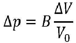
- a deformation of the elastomer or dielectric material based on a pressure change ⁇ p may cause a proportional volume change ⁇ V in view of an initial volume V 0 at an initial pressure.
- a volume change may be calculated based on a change of the capacitance of the capacitive pressure sensor.
- r o is the radius of the outer flexible electrode
- r i is the radius of the inner (rigid) electrode
- ⁇ 0 is the absolute permittivity or absolute dielectric constant
- ⁇ r is the relative permittivity or relative dielectric constant.
- an alarm is output if the first pressure value p 1 or the second pressure value p 2 drops below a minimum pressure value piow of the gas filling.
- this alarm can be output via a signal lamp and/or a wireless interface so as to inform responsible personnel. In this way, exceptional pressure drops can be recognized.
- the predefined temperature T p or the predefined temperature range is chosen according to the IEC standard IEC 62271-100/200 or a nominal temperature operating range of the electrical switchgear. In this way, suitable predefined temperatures T p or temperature ranges may be chosen.
- Fig. 1 shows a schematic view of an electrical switchgear 1, which comprises a gas filling 2 in a gas tank 3 within a housing 4 of the electrical switchgear 1.
- the gas filling 2 has the pressure p, the volume V gas and the temperature T.
- the electrical switchgear 1 comprises a capacitive pressure sensor 5 with an outer electrode 6, an inner electrode 7 and a dielectric material 8 in-between as well as a base 9.
- the dielectric material 8 may consist of or comprise an elastomer.
- the pressure p of the gas filling 2 can be calculated based on a volume change of the capacitor formed by the electrodes 5 and 6 and the dielectric material 8.
- a temperature sensor 10 is arranged on the base 9.
- the capacitive pressure sensor 5 and the temperature sensor 10 are connected to an evaluation unit 11a, which comprises a processor 12, a memory 13 and a wireless interface 14.
- a signal lamp 15 is connected to the evaluation unit 11a.
- the electrical switchgear 1 comprises an exemplary switching device 16 arranged in the gas filling 2.
- the gas tank 3 may be part of a larger system filled with the gas filling 2.
- the system may comprise additional chambers, tubes and so on.
- the pressure sensor 5 and/or the temperature sensor 10 are not necessarily arranged in the gas tank 3 but may be arranged at another position within the system filled with the insulating gas.
- the function of the electrical switchgear 1 is now as follows: Initially, the system and thus the gas tank 3 are filled with an insulating gas forming the gas filling 2 of the electrical switchgear 1.
- the insulating gas may consist of or comprise Sulfur hexafluoride (SF6).
- SF6 Sulfur hexafluoride
- the gas filling 2 may leak from the system, in particular from the gas tank 3, so that the insulating function may decrease.
- a minimum pressure value piow of the gas filling 2 can be defined. Once the pressure p of the gas filling 2 drops below this minimum pressure value p low , operation of the electrical switchgear 1 can get dangerous. That is why it is advisable to stop the operation of the electrical switchgear 1 in such a situation.
- the lifetime of the gas filling 2 is predicted according to the following method, which comprises the steps of:
- p 1 is the first pressure value
- p 2 is the second pressure value
- ⁇ p is the pressure difference between the second pressure value p 2 and the first pressure value p 1
- t 1 is the first point in time and t 2 is the second point in time
- ⁇ t is the time difference between the second point in time t 2 and the first point in time t 1
- ⁇ p ptu is the nominal pressure drop per time unit (for example per year)
- LT nominal is the nominal lifetime of the gas filling 2
- piow is the minimum pressure value of
- piow is the minimum pressure value of the gas filling 2 above which safe operation of the electrical switchgear 1 is ensured.
- the maximum pressure value p high of the gas filling 2 normally is the initial pressure when the system or gas tank 3 is filled.
- the nominal lifetime LT nominal of the gas filling 2 is the expected lifetime of the gas filling 2, e.g. 30 years.
- the nominal pressure drop per time unit ⁇ p ptu corresponds to the nominal lifetime LT nominal of the gas filling 2 and the difference between the maximum pressure value p high and the minimum pressure value piow of the gas filling 2.
- the pressure p of the gas filling 2 is measured by means of the pressure sensor 5, in this embodiment by measuring the capacitance formed by the electrodes 6 and 7.
- the pressure sensor 5 In this embodiment, it is proposed to take pressure values at the same predefined temperature T p or at least at temperatures T within a predetermined temperature range.
- switching arcs during opening of the switching contacts of the switching device 16 can heat up the gas filling 2 quickly and cause spikes in graphs of the pressure p and the temperature T of the gas filling 2.
- Tests and investigations revealed that there is a time difference between the spikes of the pressure p and the temperature T.
- the processor 12 of the evaluation unit 11a may continuously (i.e. in predetermined time intervals) take measurements of the pressure p by use of the pressure sensor 5 and measurements of the temperature T by use of the temperature sensor 10 and store the same in the memory 13. For calculation of the lifetime of the gas filling 2, measured values may be read from the memory 13 and used for the above calculations. Alternatively, the processor 12 may monitor the temperature T by use of the temperature sensor 10 and measure the pressure p at suitable temperatures.
- the predefined temperature T p or the predefined temperature range may be chosen according to the IEC standard IEC 62271-100/200 or a nominal temperature operating range of the electrical switchgear 1. In this way, suitable predefined temperatures T p or temperature ranges may be chosen.
- an alarm can be output if the first pressure value p 1 or the second pressure value p 2 drops below the minimum pressure value piow of the gas filling 2.
- this alarm can be output via the signal lamp 15 and/or the wireless interface 14 so as to inform responsible personnel. In this way, exceptional pressure drops can be recognized.
- the pressure p may be determined more accurately when a temperature range is defined for taking pressure measurements.
- the reference temperature T ref is within said temperature range.
- the pressure p of the gas filling 2 can be calculated based on a volume change of the capacitor formed by the electrodes 6 and 7 and the dielectric material 8 as mentioned hereinbefore.
- a deformation of the elastomer or dielectric material 8 based on a pressure change ⁇ p causes a proportional volume change ⁇ V in view of an initial volume Vo at an initial pressure.
- a volume change ⁇ V may easily be calculated based on a change of the capacitance of the capacitive pressure sensor 5.
- the volume change ⁇ V and thus the pressure change ⁇ p can easily be calculated.
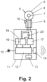
- Fig. 2 finally shows a more detailed embodiment of an evaluation unit 11b, which in addition to the parts of the evaluation unit 11a of Fig. 1 comprises a signal injector 17, a signal conditioner 18, a signal amplifier 19 and a capacitor 20.
- the signal injector 17 is provided to apply a signal to the serial connection of the capacitor 20 and the capacitive pressure sensor 5.
- the signal conditioner 18 is provided to generate a pressure signal based on the voltage across the capacitor 20 and based on the signal of the temperature sensor 10.
- the signal amplifier 19 finally amplifies the signal from the signal conditioner 18 and outputs its signal to the processor 12.
- the invention is not limited to the embodiments disclosed hereinbefore, but combinations of the different variants are possible.
- the electrical switchgear 1 and the evaluation unit 11a, 11b may have more or less parts than shown in the figures.
- the description may comprise subject matter of further independent inventions.
Landscapes
- Physics & Mathematics (AREA)
- General Physics & Mathematics (AREA)
- Gas-Insulated Switchgears (AREA)
- Examining Or Testing Airtightness (AREA)
Abstract
Description
- The invention relates to a method of predicting a lifetime of a gas filling of an electrical switchgear.
- Initially, the system of an electrical switchgear can be filled with an insulating gas forming the gas filling of the electrical switchgear. For example, the insulating gas may consist of or comprise Sulfur hexafluoride (SF6). Over time, the gas filling may leak from the system so that the insulating function may decrease. To ensure a minimum of the insulating function, e.g. for switching devices arranged within the gas filled system, a minimum pressure value of the gas filling can be defined. Once the pressure of the gas filling drops below this minimum pressure value, operation of the electrical switchgear can get dangerous. That is why it is advisable to stop the operation of the electrical switchgear in such a situation. Unfortunately, such a situation may occur unexpectedly and lead to an unwanted downtime of the electrical switchgear.
- Accordingly, an object of the invention is the provision of a method of predicting a lifetime of a gas filling of an electrical switchgear. In particular, an unexpected downtime of an electrical switchgear shall be avoided.
- The object of the invention is solved by a method of predicting a lifetime of a gas filling of an electrical switchgear, which comprises the steps of
- a) measuring a first pressure value p1 in a system of the electrical switchgear containing the gas filling at a predefined temperature Tp at a first point in time t1 and measuring a second pressure value p2 in the system of the electrical switchgear containing the gas filling at the same predefined temperature Tp at a second point in time t2 or
- b) measuring a first pressure value p1 in a system of the electrical switchgear containing the gas filling at a first temperature T1 within a predefined temperature range at a first point in time t1 and measuring a second pressure value p2 in the system of the electrical switchgear containing the gas filling at a second temperature T2 within the same predefined temperature range at a second point in time t2,
- calculating a pressure difference Δp between the first pressure value p1 and the second pressure value p2 and
- calculating a lifetime of the gas filling based on said pressure difference Δp.
- In this way, unexpected downtimes of the electrical switchgear can be avoided, and maintenance of the electrical switchgear can be planned better.
- To avoid that fast temperature changes of the gas filling, which may be caused by a switching operation of a switching device arranged within the gas filled system, it is proposed to take pressure values at the same predefined temperature Tp or at least at temperatures within a predetermined temperature range. In particular, switching arcs during opening of the switching contacts of such a switching device can heat up the gas filling quickly and cause spikes in graphs of the pressure p and the temperature T of the gas filling. Tests and investigations revealed that there is a time difference between the spikes of the pressure p and the temperature T. Hence, using the gas equation

- In particular the total lifetime LTtotal of the gas filling can be calculated by use of the formulas


- The minimum pressure value piow of the gas filling ensures a minimum level of insulation. Below that value, operation of the electrical switchgear may get dangerous. The maximum pressure value phigh of the gas filling normally is the initial pressure when the system is filled. The nominal lifetime LTnominal of the gas filling is the expected lifetime of the gas filling, e.g. 30 years. The nominal pressure drop per time unit Δpptu corresponds to this nominal lifetime LTnominal and the difference between the maximum pressure value phigh and the minimum pressure value plow.
- A remaining lifetime LTremain of the gas filling can be calculated by use of the formula

- In another embodiment, the total lifetime LTtotal of the gas filling can be calculated by use of the formula

- Further on, the remaining lifetime LTremain of the gas filling can be calculated by use of the formula

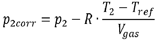
- In an advantageous embodiment, the first pressure value p1 can be replaced by p1corr and referenced to a reference temperature Tref and/or the second pressure value p2 can be replaced by p2corr and referenced to a reference temperature Tref in the aforementioned formulas by use of the following formulas


- Preferably, the first pressure value p1 and/or the second pressure value p2 is calculated based on a volume change of a capacitor having an elastomer as a dielectric material between two electrodes of the capacitor.
- In detail, a deformation of the elastomer or dielectric material based on a pressure change Δp may cause a proportional volume change ΔV in view of an initial volume V0 at an initial pressure. The proportionality factor usually is denoted B, and the formula for the pressure change Δp reads as
- A volume change may be calculated based on a change of the capacitance of the capacitive pressure sensor. Provided that the capacitor is ball shaped, the capacitance C can be calculated by use of the formula

- Wherein ro is the radius of the outer flexible electrode, ri is the radius of the inner (rigid) electrode, ε0 is the absolute permittivity or absolute dielectric constant and εr is the relative permittivity or relative dielectric constant. Based on the known radius ri of the inner (rigid) electrode and the radius ro of the outer flexible electrode at an initial pressure and an actual pressure, the volume change ΔV and thus the pressure change Δp can easily be calculated. Of course, other shapes of capacitive pressure sensors work as well, for example cylindrical shapes.
- Preferably, an alarm is output if the first pressure value p1 or the second pressure value p2 drops below a minimum pressure value piow of the gas filling. For example, this alarm can be output via a signal lamp and/or a wireless interface so as to inform responsible personnel. In this way, exceptional pressure drops can be recognized.
- Advantageously, the predefined temperature Tp or the predefined temperature range is chosen according to the IEC standard IEC 62271-100/200 or a nominal temperature operating range of the electrical switchgear. In this way, suitable predefined temperatures Tp or temperature ranges may be chosen.
- The invention now is described in more detail hereinafter with reference to particular embodiments, which the invention however is not limited to.
- Fig. 1
- shows a schematic view of an electrical switchgear and
- Fig. 2
- shows a more detailed embodiment of an evaluation unit.
- Generally, same parts or similar parts are denoted with the same/similar names and reference signs. The features disclosed in the description apply to parts with the same/similar names respectively reference signs. Indicating the orientation and relative position is related to the associated figure, and indication of the orientation and/or relative position has to be amended in different figures accordingly as the case may be.
-
Fig. 1 shows a schematic view of an electrical switchgear 1, which comprises a gas filling 2 in agas tank 3 within ahousing 4 of the electrical switchgear 1. The gas filling 2 has the pressure p, the volume Vgas and the temperature T. - In the
gas tank 3, the electrical switchgear 1 comprises acapacitive pressure sensor 5 with anouter electrode 6, aninner electrode 7 and adielectric material 8 in-between as well as abase 9. Thedielectric material 8 may consist of or comprise an elastomer. The pressure p of the gas filling 2 can be calculated based on a volume change of the capacitor formed by theelectrodes dielectric material 8. - Moreover, a
temperature sensor 10 is arranged on thebase 9. Thecapacitive pressure sensor 5 and thetemperature sensor 10 are connected to an evaluation unit 11a, which comprises aprocessor 12, amemory 13 and awireless interface 14. Moreover, asignal lamp 15 is connected to the evaluation unit 11a. Finally, the electrical switchgear 1 comprises anexemplary switching device 16 arranged in the gas filling 2. - It should be noted that the
gas tank 3 may be part of a larger system filled with the gas filling 2. For example, the system may comprise additional chambers, tubes and so on. Accordingly, thepressure sensor 5 and/or thetemperature sensor 10 are not necessarily arranged in thegas tank 3 but may be arranged at another position within the system filled with the insulating gas. - The function of the electrical switchgear 1 is now as follows:
Initially, the system and thus thegas tank 3 are filled with an insulating gas forming the gas filling 2 of the electrical switchgear 1. For example, the insulating gas may consist of or comprise Sulfur hexafluoride (SF6). Over time, the gas filling 2 may leak from the system, in particular from thegas tank 3, so that the insulating function may decrease. To ensure a minimum of the insulating function, e.g. for theswitching device 16 and other devices as the case may be, a minimum pressure value piow of the gas filling 2 can be defined. Once the pressure p of the gas filling 2 drops below this minimum pressure value plow, operation of the electrical switchgear 1 can get dangerous. That is why it is advisable to stop the operation of the electrical switchgear 1 in such a situation. - To avoid unexpected downtimes of the electrical switchgear 1, the lifetime of the gas filling 2 is predicted according to the following method, which comprises the steps of:
- a) measuring a first pressure value p1 in the system of the electrical switchgear 1 containing the gas filling 2 at a predefined temperature Tp at a first point in time t1 and measuring a second pressure value p2 in the system of the electrical switchgear 1 containing the gas filling 2 at the same predefined temperature Tp at a second point in time t2 or
- b) measuring a first pressure value p1 in the system of the electrical switchgear 1 containing the gas filling 2 at a first temperature T1 within a predefined temperature range at a first point in time t1 and measuring a second pressure value p2 in the system of the electrical switchgear 1 containing the gas filling 2 at a second temperature T2 within the same predefined temperature range at a second point in time t2,
- calculating a pressure difference Δp between the first pressure value p1 and the second pressure value p2 and
- calculating the lifetime of the gas filling 2 based on said pressure difference Δp.
- In particular, the total lifetime LTtotal of the gas filling can be calculated by use of the formulas

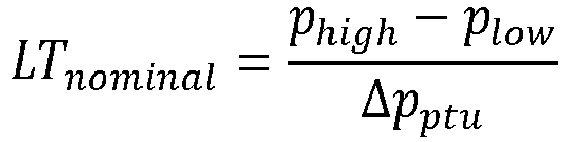

- As already mentioned, piow is the minimum pressure value of the gas filling 2 above which safe operation of the electrical switchgear 1 is ensured. The maximum pressure value phigh of the gas filling 2 normally is the initial pressure when the system or
gas tank 3 is filled. The nominal lifetime LTnominal of the gas filling 2 is the expected lifetime of the gas filling 2, e.g. 30 years. The nominal pressure drop per time unit Δpptu corresponds to the nominal lifetime LTnominal of the gas filling 2 and the difference between the maximum pressure value phigh and the minimum pressure value piow of the gas filling 2. - A remaining lifetime LTremain of the gas filling 2 can be calculated by use of the formula

- In detail, the pressure p of the gas filling 2 is measured by means of the
pressure sensor 5, in this embodiment by measuring the capacitance formed by theelectrodes switching device 16, it is proposed to take pressure values at the same predefined temperature Tp or at least at temperatures T within a predetermined temperature range. In particular switching arcs during opening of the switching contacts of theswitching device 16 can heat up the gas filling 2 quickly and cause spikes in graphs of the pressure p and the temperature T of the gas filling 2. Tests and investigations revealed that there is a time difference between the spikes of the pressure p and the temperature T. Using the gas equation
switching device 16. However, that does not necessarily mean that pressure values are only taken at a predetermined temperature Tp or within a temperature range, but pressure p can be measured continuously, and suitable values can be picked out of the data stream for the lifetime prediction calculation. - So, in detail the
processor 12 of the evaluation unit 11a may continuously (i.e. in predetermined time intervals) take measurements of the pressure p by use of thepressure sensor 5 and measurements of the temperature T by use of thetemperature sensor 10 and store the same in thememory 13. For calculation of the lifetime of the gas filling 2, measured values may be read from thememory 13 and used for the above calculations. Alternatively, theprocessor 12 may monitor the temperature T by use of thetemperature sensor 10 and measure the pressure p at suitable temperatures. - The predefined temperature Tp or the predefined temperature range may be chosen according to the IEC standard IEC 62271-100/200 or a nominal temperature operating range of the electrical switchgear 1. In this way, suitable predefined temperatures Tp or temperature ranges may be chosen.
- In a preferred embodiment, an alarm can be output if the first pressure value p1 or the second pressure value p2 drops below the minimum pressure value piow of the gas filling 2. For example, this alarm can be output via the
signal lamp 15 and/or thewireless interface 14 so as to inform responsible personnel. In this way, exceptional pressure drops can be recognized. - In another embodiment, the total lifetime LTtotal of the gas filling 2 can be calculated by use of the formula


- In all embodiments, beneficially the first pressure value p1 can be replaced by p1corr and referenced to a reference temperature Tref and/or the second pressure value p2 can be replaced by p2corr and referenced to a reference temperature Tref in the aforementioned formulas by use of the formulas

- Generally, the pressure p of the gas filling 2 can be calculated based on a volume change of the capacitor formed by the
electrodes dielectric material 8 as mentioned hereinbefore. In detail, a deformation of the elastomer ordielectric material 8 based on a pressure change Δp causes a proportional volume change ΔV in view of an initial volume Vo at an initial pressure. The proportionality factor usually is denoted B, and the formula for the pressure change Δp reads as
- A volume change ΔV may easily be calculated based on a change of the capacitance of the
capacitive pressure sensor 5. Provided that the capacitor is ball shaped, the capacitance C can be calculated by use of the formula
flexible electrode 6, ri is the radius of the inner (rigid)electrode 7, ε0 is the absolute permittivity or absolute dielectric constant and εr is the relative permittivity or relative dielectric constant. Based on the known the radius ri of the inner (rigid)electrode 7, the radius ro of the outerflexible electrode 6 at an initial pressure and an actual pressure, the volume change ΔV and thus the pressure change Δp can easily be calculated. -
Fig. 2 finally shows a more detailed embodiment of an evaluation unit 11b, which in addition to the parts of the evaluation unit 11a ofFig. 1 comprises asignal injector 17, asignal conditioner 18, asignal amplifier 19 and acapacitor 20. Thesignal injector 17 is provided to apply a signal to the serial connection of thecapacitor 20 and thecapacitive pressure sensor 5. Thesignal conditioner 18 is provided to generate a pressure signal based on the voltage across thecapacitor 20 and based on the signal of thetemperature sensor 10. Thesignal amplifier 19 finally amplifies the signal from thesignal conditioner 18 and outputs its signal to theprocessor 12. - It is noted that the invention is not limited to the embodiments disclosed hereinbefore, but combinations of the different variants are possible. In reality, the electrical switchgear 1 and the evaluation unit 11a, 11b may have more or less parts than shown in the figures. Moreover, the description may comprise subject matter of further independent inventions.
- It should also be noted that the term "comprising" does not exclude other elements and the use of articles "a" or "an" does not exclude a plurality. Also elements described in association with different embodiments may be combined. It should also be noted that reference signs in the claims should not be construed as limiting the scope of the claims.
-
- 1
- electrical switchgear
- 2
- gas filling
- 3
- gas tank
- 4
- housing
- 5
- pressure sensor
- 6
- outer electrode
- 7
- inner electrode
- 8
- dielectric material
- 9
- base
- 10
- temperature sensor
- 11a, 11b
- evaluation unit
- 12
- processor
- 13
- memory
- 14
- wireless interface
- 15
- signal lamp
- 16
- switching device
- 17
- signal injector
- 18
- signal conditioner
- 19
- signal amplifier
- 20
- capacitor
- p
- pressure
- T
- temperature
- Vgas
- volume of gas filling
Claims (9)
- Method of predicting a lifetime of a gas filling (2) of an electrical switchgear (1), comprising the steps ofa) measuring a first pressure value p1 in a system of the electrical switchgear (1) containing the gas filling (2) at a predefined temperature Tp at a first point in time t1 and measuring a second pressure value p2 in the system of the electrical switchgear (1) containing the gas filling (2) at the same predefined temperature Tp at a second point in time t2 orb) measuring a first pressure value p1 in a system of the electrical switchgear (1) containing the gas filling (2) at a first temperature T1 within a predefined temperature range at a first point in time t1 and measuring a second pressure value p2 in the system of the electrical switchgear (1) containing the gas filling (2) at a second temperature T2 within the same predefined temperature range at a second point in time t2,- calculating a pressure difference Δp between the first pressure value p1 and the second pressure value p2 and- calculating a lifetime of the gas filling (2) based on said pressure difference Δp, characterized in that the first pressure value p1 and/or the second pressure value p2 is calculated based on a volume change of a capacitor having an elastomer as a dielectric material (8) between two electrodes (6, 7) of the capacitor.
- Method as claimed in claim 1, characterized in that the total lifetime LTtotal of the gas filling is calculated by use of the formulas


- Method as claimed in claim 2, characterized in that the remaining lifetime LTremain of the gas filling (2) is calculated by use of the formula

- Method as claimed in claim 1 or 3, characterized in that the total lifetime LTtotal of the gas filling (2) is calculated by use of the formula

- Method as claimed in claim 1, 2 or 4, characterized in that the remaining lifetime LTremain of the gas filling (2) is calculated by use of the formula

- Method as claimed in any one of claims 1 to 5, characterized in that the first pressure value p1 is replaced by p1corr and referenced to a reference temperature Tref and/or the second pressure value p2 is replaced by p2corr and referenced to a reference temperature Tref by use of the formula


- Method as claimed in any one of claims 1 to 6, characterized in that an alarm is output if the first pressure value p1 or the second pressure value p2 drops below a minimum pressure value plow of the gas filling (2).
- Method as claimed in any one of claims 1 to 7, characterized in that the predefined temperature Tp or the predefined temperature range is chosen according to the IEC standard IEC 62271-100/200 or a nominal temperature operating range of the electrical switchgear (1).
- A system for predicting a lifetime of a gas filling (2) of an electrical switchgear (1), the system comprising:i. a pressure sensor (5) for measuring a pressure value in a system of the electrical switchgear (1), said pressure sensor (5) including a capacitor having an elastomer as a dielectric material (8) between two electrodes (6, 7) of the capacitor,ii. a temperature sensor (10) for measuring a pressure value in a system of the electrical switchgear (1),iii. an evaluation unit (11a), which comprises a processor (12) and a memory (13), said capacitive pressure sensor (5) and the temperature sensor (10) being connected to the evaluation unit (11a),wherein the system is configured to perform the steps of:a) measuring, using said pressure sensor (5), a first pressure value p1 in a system of the electrical switchgear (1) containing the gas filling (2) at a predefined temperature Tp, measured using said temperature sensor (10), at a first point in time t1 and measuring a second pressure value p2, using said pressure sensor (5), in the system of the electrical switchgear (1) containing the gas filling (2) at the same predefined temperature Tp, measured using said temperature sensor (10), at a second point in time t2 orb) measuring, using said pressure sensor (5), a first pressure value p1 in a system of the electrical switchgear (1) containing the gas filling (2) at a first temperature T1, measured using said temperature sensor (10), within a predefined temperature range at a first point in time t1 and measuring a second pressure value p2, measured using said pressure sensor (5), in the system of the electrical switchgear (1) containing the gas filling (2) at a second temperature T2, measured using said temperature sensor (10), within the same predefined temperature range at a second point in time t2,- calculating a pressure difference Δp between the first pressure value p1 and the second pressure value p2 and- calculating a lifetime of the gas filling (2) based on said pressure difference Δp, wherein, the first pressure value p1 and/or the second pressure value p2 is calculated based on a volume change of a capacitor having an elastomer as a dielectric material (8) between two electrodes (6, 7) of the capacitor.
Applications Claiming Priority (2)
| Application Number | Priority Date | Filing Date | Title |
|---|---|---|---|
| IN202111040504 | 2021-09-07 | ||
| GB2115415.8A GB2610443A (en) | 2021-09-07 | 2021-10-27 | Lifetime prediction of a gas filling of an electrical switchgear |
Publications (2)
| Publication Number | Publication Date |
|---|---|
| EP4145650A1 true EP4145650A1 (en) | 2023-03-08 |
| EP4145650B1 EP4145650B1 (en) | 2024-10-09 |
Family
ID=83081275
Family Applications (1)
| Application Number | Title | Priority Date | Filing Date |
|---|---|---|---|
| EP22192301.4A Active EP4145650B1 (en) | 2021-09-07 | 2022-08-26 | Lifetime prediction of a gas filling of an electrical switchgear |
Country Status (5)
| Country | Link |
|---|---|
| US (1) | US11927618B2 (en) |
| EP (1) | EP4145650B1 (en) |
| JP (1) | JP7397143B2 (en) |
| CN (1) | CN115773964B (en) |
| PL (1) | PL4145650T3 (en) |
Cited By (1)
| Publication number | Priority date | Publication date | Assignee | Title |
|---|---|---|---|---|
| CN119780690A (en) * | 2024-12-13 | 2025-04-08 | 湘潭大学 | A method for evaluating breakdown delay and jitter performance of gas switches |
Families Citing this family (3)
| Publication number | Priority date | Publication date | Assignee | Title |
|---|---|---|---|---|
| EP4269976B1 (en) * | 2022-04-28 | 2024-12-25 | Schneider Electric Industries Sas | Method for determining a gas quantity in an insulated switchgear |
| DE102024204770A1 (en) * | 2024-05-23 | 2025-11-27 | Siemens Aktiengesellschaft | Gas-insulated switchgear |
| CN121068191B (en) * | 2025-11-07 | 2026-01-30 | 山东电工电气日立高压开关有限公司 | System and method for testing mechanical life of isolation grounding switch |
Citations (2)
| Publication number | Priority date | Publication date | Assignee | Title |
|---|---|---|---|---|
| JPH05115111A (en) * | 1991-10-18 | 1993-05-07 | Mitsubishi Electric Corp | Gas leakage monitor for gas insulated electric apparatus |
| JP2020072614A (en) * | 2018-11-02 | 2020-05-07 | 株式会社近計システム | Gas pressure monitoring device of gas insulation breaker |
Family Cites Families (20)
| Publication number | Priority date | Publication date | Assignee | Title |
|---|---|---|---|---|
| JP2003011799A (en) * | 2001-06-28 | 2003-01-15 | Tokico Ltd | Compressed gas filling apparatus and compressed gas filling method |
| JP4337455B2 (en) * | 2003-07-25 | 2009-09-30 | パナソニック株式会社 | Capacitor |
| DE102004036133B4 (en) * | 2004-07-24 | 2006-07-06 | Festo Ag & Co. | Test gas volume determining method for e.g. container, involves determining pressure-measured values of two volumes, total pressure-measured value of two volumes, determining one volume value based on measured valves |
| US7257496B2 (en) | 2005-07-28 | 2007-08-14 | Avistar, Inc. | Method and apparatus for monitoring SF6 gas and electric utility apparatus |
| DE102006050938A1 (en) | 2006-10-28 | 2008-04-30 | Abb Technology Ag | Foresight determination method for process variable, involves assigning discrete measured value to each weighted measured value, and measuring future temporal process of process variable by linear regression of discrete measured value |
| US20080157783A1 (en) * | 2007-01-01 | 2008-07-03 | Maxwell Technologies, Inc. | Apparatus and method for monitoring high voltage capacitors |
| DE102008063682A1 (en) * | 2008-12-19 | 2010-06-24 | Abb Technology Ag | Unit for monitoring and / or signaling / visualization of operating variables of a gas-insulated switchgear |
| ES2632966T3 (en) * | 2009-01-30 | 2017-09-18 | Wika Alexander Wiegand Gmbh & Co. Kg | Measuring device for determining the filling amount of an SF6 gas in an isolation chamber or in a corresponding switching and procedure installation |
| FR2965120B1 (en) * | 2010-09-22 | 2012-10-12 | Areva T & D Sas | APPARATUS FOR BREAKING A MEDIUM OR HIGH VOLTAGE ELECTRIC CURRENT AND METHOD FOR MANUFACTURING THE SAME |
| JP5349520B2 (en) | 2011-03-29 | 2013-11-20 | 中国電力株式会社 | Gas pressure monitoring and control device |
| FR3001345B1 (en) * | 2013-01-22 | 2016-01-22 | Alstom Technology Ltd | DETERMINING A LEAKAGE RATE OF AN ISOLATION GAS |
| JP2015187561A (en) | 2014-03-26 | 2015-10-29 | 株式会社日本自動車部品総合研究所 | Pressure sensor |
| US9696248B2 (en) * | 2014-04-29 | 2017-07-04 | Solon Manufacturing Company | Gas insulated switchgear monitoring apparatus and method |
| KR20160143140A (en) * | 2015-06-04 | 2016-12-14 | 엘에스산전 주식회사 | System for assessing health index of power apparatus |
| WO2017099118A1 (en) * | 2015-12-11 | 2017-06-15 | Honda Motor Co., Ltd. | Process for refilling a gas tank and gas supply system |
| EP3621096A1 (en) | 2018-09-07 | 2020-03-11 | Siemens Aktiengesellschaft | Gas monitoring system for gas-insulated switchgears |
| US11909389B2 (en) | 2019-07-17 | 2024-02-20 | Panasonic Intellectual Property Management Co., Ltd. | Input device and input system |
| CN112051181A (en) * | 2020-09-10 | 2020-12-08 | 国网宁夏电力有限公司电力科学研究院 | A portable transformer oil gas content measuring device |
| CN112382525A (en) * | 2020-10-23 | 2021-02-19 | 杭州王之新创信息技术研究有限公司 | Extra-high voltage power switch |
| CN113295394B (en) * | 2021-05-21 | 2023-10-31 | 上海三一重机股份有限公司 | Gas pressure circulation test method and device |
-
2022
- 2022-08-26 PL PL22192301.4T patent/PL4145650T3/en unknown
- 2022-08-26 EP EP22192301.4A patent/EP4145650B1/en active Active
- 2022-09-01 US US17/929,091 patent/US11927618B2/en active Active
- 2022-09-05 CN CN202211077539.8A patent/CN115773964B/en active Active
- 2022-09-07 JP JP2022141798A patent/JP7397143B2/en active Active
Patent Citations (2)
| Publication number | Priority date | Publication date | Assignee | Title |
|---|---|---|---|---|
| JPH05115111A (en) * | 1991-10-18 | 1993-05-07 | Mitsubishi Electric Corp | Gas leakage monitor for gas insulated electric apparatus |
| JP2020072614A (en) * | 2018-11-02 | 2020-05-07 | 株式会社近計システム | Gas pressure monitoring device of gas insulation breaker |
Cited By (1)
| Publication number | Priority date | Publication date | Assignee | Title |
|---|---|---|---|---|
| CN119780690A (en) * | 2024-12-13 | 2025-04-08 | 湘潭大学 | A method for evaluating breakdown delay and jitter performance of gas switches |
Also Published As
| Publication number | Publication date |
|---|---|
| JP7397143B2 (en) | 2023-12-12 |
| CN115773964B (en) | 2025-08-26 |
| PL4145650T3 (en) | 2024-12-16 |
| US20230076611A1 (en) | 2023-03-09 |
| JP2023038941A (en) | 2023-03-17 |
| CN115773964A (en) | 2023-03-10 |
| EP4145650B1 (en) | 2024-10-09 |
| US11927618B2 (en) | 2024-03-12 |
Similar Documents
| Publication | Publication Date | Title |
|---|---|---|
| EP4145650B1 (en) | Lifetime prediction of a gas filling of an electrical switchgear | |
| EP2438405B1 (en) | Aircraft fuel level measurement apparatus and method | |
| US10422680B2 (en) | Method for monitoring at least one media-specific property of a medium | |
| US8400320B2 (en) | System for monitoring oil level and detecting leaks in power transformers, reactors, current and potential transformers, high voltage bushings and the like | |
| EP1982156B1 (en) | Pressure sensor fault detection | |
| KR20150043162A (en) | Apparatus and method for real time monitoring of sulfur hexaflouride gas | |
| JP2515425B2 (en) | Differential pressure measuring device | |
| CN107305150B (en) | Vacuum gauge state detection method and system | |
| EP3185024A1 (en) | Current transformer with enhanced temperature measurement functions | |
| US20130221986A1 (en) | Method for Calibrating a Conductivity Measuring Cell | |
| KR20110108550A (en) | Leakage measuring device for gas insulated transmission line | |
| JPH05283240A (en) | Oil-filled transformer | |
| US20230042239A1 (en) | Capacitive filling level probe without dead zone | |
| EP2088440A1 (en) | Monitoring of capacitor | |
| US12546678B2 (en) | Method for determining a gas quantity in an insulated switchgear | |
| GB2610443A (en) | Lifetime prediction of a gas filling of an electrical switchgear | |
| WO2012157134A1 (en) | Device for detecting deterioration in degree of vacuum of hermetic opening and closing device | |
| US3964037A (en) | Fuel tank alarm systems | |
| JPH07129870A (en) | Gas leak detection device for gas insulated switchgear | |
| JP3367168B2 (en) | Level measuring method and level measuring instrument | |
| US20170221659A1 (en) | Device for monitoring the vacuum quality of a vacuum circuit breaker | |
| JP2836768B2 (en) | Gas leak monitoring device for gas insulated electrical equipment | |
| US20240011857A1 (en) | Measuring arrangement and method for operating a measuring arrangement | |
| KR102808541B1 (en) | Apparatus and method for detecting gas status in sulfur hexafluoride gas pipe | |
| KR20080074095A (en) | Voltage detector and voltage sensing method for gas insulated switchgear |
Legal Events
| Date | Code | Title | Description |
|---|---|---|---|
| PUAI | Public reference made under article 153(3) epc to a published international application that has entered the european phase |
Free format text: ORIGINAL CODE: 0009012 |
|
| STAA | Information on the status of an ep patent application or granted ep patent |
Free format text: STATUS: REQUEST FOR EXAMINATION WAS MADE |
|
| 17P | Request for examination filed |
Effective date: 20220826 |
|
| AK | Designated contracting states |
Kind code of ref document: A1 Designated state(s): AL AT BE BG CH CY CZ DE DK EE ES FI FR GB GR HR HU IE IS IT LI LT LU LV MC MK MT NL NO PL PT RO RS SE SI SK SM TR |
|
| P01 | Opt-out of the competence of the unified patent court (upc) registered |
Effective date: 20230521 |
|
| GRAP | Despatch of communication of intention to grant a patent |
Free format text: ORIGINAL CODE: EPIDOSNIGR1 |
|
| STAA | Information on the status of an ep patent application or granted ep patent |
Free format text: STATUS: GRANT OF PATENT IS INTENDED |
|
| RIC1 | Information provided on ipc code assigned before grant |
Ipc: H02B 13/035 20060101ALN20240704BHEP Ipc: G01L 13/02 20060101ALI20240704BHEP Ipc: G01L 9/00 20060101ALI20240704BHEP Ipc: H01H 33/56 20060101ALI20240704BHEP Ipc: H02B 13/065 20060101AFI20240704BHEP |
|
| INTG | Intention to grant announced |
Effective date: 20240712 |
|
| GRAS | Grant fee paid |
Free format text: ORIGINAL CODE: EPIDOSNIGR3 |
|
| GRAA | (expected) grant |
Free format text: ORIGINAL CODE: 0009210 |
|
| STAA | Information on the status of an ep patent application or granted ep patent |
Free format text: STATUS: THE PATENT HAS BEEN GRANTED |
|
| AK | Designated contracting states |
Kind code of ref document: B1 Designated state(s): AL AT BE BG CH CY CZ DE DK EE ES FI FR GB GR HR HU IE IS IT LI LT LU LV MC MK MT NL NO PL PT RO RS SE SI SK SM TR |
|
| REG | Reference to a national code |
Ref country code: CH Ref legal event code: EP |
|
| REG | Reference to a national code |
Ref country code: DE Ref legal event code: R096 Ref document number: 602022006650 Country of ref document: DE |
|
| REG | Reference to a national code |
Ref country code: IE Ref legal event code: FG4D |
|
| REG | Reference to a national code |
Ref country code: NL Ref legal event code: FP |
|
| REG | Reference to a national code |
Ref country code: SE Ref legal event code: TRGR |
|
| REG | Reference to a national code |
Ref country code: LT Ref legal event code: MG9D |
|
| REG | Reference to a national code |
Ref country code: AT Ref legal event code: MK05 Ref document number: 1731649 Country of ref document: AT Kind code of ref document: T Effective date: 20241009 |
|
| PG25 | Lapsed in a contracting state [announced via postgrant information from national office to epo] |
Ref country code: HR Free format text: LAPSE BECAUSE OF FAILURE TO SUBMIT A TRANSLATION OF THE DESCRIPTION OR TO PAY THE FEE WITHIN THE PRESCRIBED TIME-LIMIT Effective date: 20241009 Ref country code: IS Free format text: LAPSE BECAUSE OF FAILURE TO SUBMIT A TRANSLATION OF THE DESCRIPTION OR TO PAY THE FEE WITHIN THE PRESCRIBED TIME-LIMIT Effective date: 20250209 Ref country code: PT Free format text: LAPSE BECAUSE OF FAILURE TO SUBMIT A TRANSLATION OF THE DESCRIPTION OR TO PAY THE FEE WITHIN THE PRESCRIBED TIME-LIMIT Effective date: 20250210 |
|
| PG25 | Lapsed in a contracting state [announced via postgrant information from national office to epo] |
Ref country code: FI Free format text: LAPSE BECAUSE OF FAILURE TO SUBMIT A TRANSLATION OF THE DESCRIPTION OR TO PAY THE FEE WITHIN THE PRESCRIBED TIME-LIMIT Effective date: 20241009 |
|
| PG25 | Lapsed in a contracting state [announced via postgrant information from national office to epo] |
Ref country code: BG Free format text: LAPSE BECAUSE OF FAILURE TO SUBMIT A TRANSLATION OF THE DESCRIPTION OR TO PAY THE FEE WITHIN THE PRESCRIBED TIME-LIMIT Effective date: 20241009 |
|
| PG25 | Lapsed in a contracting state [announced via postgrant information from national office to epo] |
Ref country code: ES Free format text: LAPSE BECAUSE OF FAILURE TO SUBMIT A TRANSLATION OF THE DESCRIPTION OR TO PAY THE FEE WITHIN THE PRESCRIBED TIME-LIMIT Effective date: 20241009 |
|
| PG25 | Lapsed in a contracting state [announced via postgrant information from national office to epo] |
Ref country code: NO Free format text: LAPSE BECAUSE OF FAILURE TO SUBMIT A TRANSLATION OF THE DESCRIPTION OR TO PAY THE FEE WITHIN THE PRESCRIBED TIME-LIMIT Effective date: 20250109 |
|
| PG25 | Lapsed in a contracting state [announced via postgrant information from national office to epo] |
Ref country code: LV Free format text: LAPSE BECAUSE OF FAILURE TO SUBMIT A TRANSLATION OF THE DESCRIPTION OR TO PAY THE FEE WITHIN THE PRESCRIBED TIME-LIMIT Effective date: 20241009 Ref country code: GR Free format text: LAPSE BECAUSE OF FAILURE TO SUBMIT A TRANSLATION OF THE DESCRIPTION OR TO PAY THE FEE WITHIN THE PRESCRIBED TIME-LIMIT Effective date: 20250110 Ref country code: AT Free format text: LAPSE BECAUSE OF FAILURE TO SUBMIT A TRANSLATION OF THE DESCRIPTION OR TO PAY THE FEE WITHIN THE PRESCRIBED TIME-LIMIT Effective date: 20241009 |
|
| PG25 | Lapsed in a contracting state [announced via postgrant information from national office to epo] |
Ref country code: RS Free format text: LAPSE BECAUSE OF FAILURE TO SUBMIT A TRANSLATION OF THE DESCRIPTION OR TO PAY THE FEE WITHIN THE PRESCRIBED TIME-LIMIT Effective date: 20250109 |
|
| PG25 | Lapsed in a contracting state [announced via postgrant information from national office to epo] |
Ref country code: SM Free format text: LAPSE BECAUSE OF FAILURE TO SUBMIT A TRANSLATION OF THE DESCRIPTION OR TO PAY THE FEE WITHIN THE PRESCRIBED TIME-LIMIT Effective date: 20241009 |
|
| PG25 | Lapsed in a contracting state [announced via postgrant information from national office to epo] |
Ref country code: DK Free format text: LAPSE BECAUSE OF FAILURE TO SUBMIT A TRANSLATION OF THE DESCRIPTION OR TO PAY THE FEE WITHIN THE PRESCRIBED TIME-LIMIT Effective date: 20241009 |
|
| REG | Reference to a national code |
Ref country code: DE Ref legal event code: R097 Ref document number: 602022006650 Country of ref document: DE |
|
| PG25 | Lapsed in a contracting state [announced via postgrant information from national office to epo] |
Ref country code: EE Free format text: LAPSE BECAUSE OF FAILURE TO SUBMIT A TRANSLATION OF THE DESCRIPTION OR TO PAY THE FEE WITHIN THE PRESCRIBED TIME-LIMIT Effective date: 20241009 |
|
| PG25 | Lapsed in a contracting state [announced via postgrant information from national office to epo] |
Ref country code: RO Free format text: LAPSE BECAUSE OF FAILURE TO SUBMIT A TRANSLATION OF THE DESCRIPTION OR TO PAY THE FEE WITHIN THE PRESCRIBED TIME-LIMIT Effective date: 20241009 |
|
| PG25 | Lapsed in a contracting state [announced via postgrant information from national office to epo] |
Ref country code: SK Free format text: LAPSE BECAUSE OF FAILURE TO SUBMIT A TRANSLATION OF THE DESCRIPTION OR TO PAY THE FEE WITHIN THE PRESCRIBED TIME-LIMIT Effective date: 20241009 |
|
| PG25 | Lapsed in a contracting state [announced via postgrant information from national office to epo] |
Ref country code: CZ Free format text: LAPSE BECAUSE OF FAILURE TO SUBMIT A TRANSLATION OF THE DESCRIPTION OR TO PAY THE FEE WITHIN THE PRESCRIBED TIME-LIMIT Effective date: 20241009 |
|
| PG25 | Lapsed in a contracting state [announced via postgrant information from national office to epo] |
Ref country code: IT Free format text: LAPSE BECAUSE OF FAILURE TO SUBMIT A TRANSLATION OF THE DESCRIPTION OR TO PAY THE FEE WITHIN THE PRESCRIBED TIME-LIMIT Effective date: 20241009 |
|
| PLBE | No opposition filed within time limit |
Free format text: ORIGINAL CODE: 0009261 |
|
| STAA | Information on the status of an ep patent application or granted ep patent |
Free format text: STATUS: NO OPPOSITION FILED WITHIN TIME LIMIT |
|
| PGFP | Annual fee paid to national office [announced via postgrant information from national office to epo] |
Ref country code: NL Payment date: 20250723 Year of fee payment: 4 |
|
| 26N | No opposition filed |
Effective date: 20250710 |
|
| PGFP | Annual fee paid to national office [announced via postgrant information from national office to epo] |
Ref country code: DE Payment date: 20250724 Year of fee payment: 4 |
|
| PGFP | Annual fee paid to national office [announced via postgrant information from national office to epo] |
Ref country code: PL Payment date: 20250724 Year of fee payment: 4 |
|
| PGFP | Annual fee paid to national office [announced via postgrant information from national office to epo] |
Ref country code: SE Payment date: 20250723 Year of fee payment: 4 |
|
| REG | Reference to a national code |
Ref country code: CH Ref legal event code: H13 Free format text: ST27 STATUS EVENT CODE: U-0-0-H10-H13 (AS PROVIDED BY THE NATIONAL OFFICE) Effective date: 20260324 |
|
| PG25 | Lapsed in a contracting state [announced via postgrant information from national office to epo] |
Ref country code: MC Free format text: LAPSE BECAUSE OF FAILURE TO SUBMIT A TRANSLATION OF THE DESCRIPTION OR TO PAY THE FEE WITHIN THE PRESCRIBED TIME-LIMIT Effective date: 20241009 |
|
| PG25 | Lapsed in a contracting state [announced via postgrant information from national office to epo] |
Ref country code: LU Free format text: LAPSE BECAUSE OF NON-PAYMENT OF DUE FEES Effective date: 20250826 |
|
| PG25 | Lapsed in a contracting state [announced via postgrant information from national office to epo] |
Ref country code: CH Free format text: LAPSE BECAUSE OF NON-PAYMENT OF DUE FEES Effective date: 20250831 |