EP4145641A1 - Female terminal fitting - Google Patents
Female terminal fitting Download PDFInfo
- Publication number
- EP4145641A1 EP4145641A1 EP21794455.2A EP21794455A EP4145641A1 EP 4145641 A1 EP4145641 A1 EP 4145641A1 EP 21794455 A EP21794455 A EP 21794455A EP 4145641 A1 EP4145641 A1 EP 4145641A1
- Authority
- EP
- European Patent Office
- Prior art keywords
- contact piece
- elastic contact
- main body
- body part
- terminal fitting
- Prior art date
- Legal status (The legal status is an assumption and is not a legal conclusion. Google has not performed a legal analysis and makes no representation as to the accuracy of the status listed.)
- Pending
Links
Images








Classifications
-
- H—ELECTRICITY
- H01—ELECTRIC ELEMENTS
- H01R—ELECTRICALLY-CONDUCTIVE CONNECTIONS; STRUCTURAL ASSOCIATIONS OF A PLURALITY OF MUTUALLY-INSULATED ELECTRICAL CONNECTING ELEMENTS; COUPLING DEVICES; CURRENT COLLECTORS
- H01R13/00—Details of coupling devices of the kinds covered by groups H01R12/70 or H01R24/00 - H01R33/00
- H01R13/02—Contact members
- H01R13/10—Sockets for co-operation with pins or blades
- H01R13/11—Resilient sockets
- H01R13/114—Resilient sockets co-operating with pins or blades having a square transverse section
-
- H—ELECTRICITY
- H01—ELECTRIC ELEMENTS
- H01R—ELECTRICALLY-CONDUCTIVE CONNECTIONS; STRUCTURAL ASSOCIATIONS OF A PLURALITY OF MUTUALLY-INSULATED ELECTRICAL CONNECTING ELEMENTS; COUPLING DEVICES; CURRENT COLLECTORS
- H01R13/00—Details of coupling devices of the kinds covered by groups H01R12/70 or H01R24/00 - H01R33/00
- H01R13/02—Contact members
- H01R13/10—Sockets for co-operation with pins or blades
- H01R13/11—Resilient sockets
-
- H—ELECTRICITY
- H01—ELECTRIC ELEMENTS
- H01R—ELECTRICALLY-CONDUCTIVE CONNECTIONS; STRUCTURAL ASSOCIATIONS OF A PLURALITY OF MUTUALLY-INSULATED ELECTRICAL CONNECTING ELEMENTS; COUPLING DEVICES; CURRENT COLLECTORS
- H01R13/00—Details of coupling devices of the kinds covered by groups H01R12/70 or H01R24/00 - H01R33/00
- H01R13/02—Contact members
- H01R13/193—Means for increasing contact pressure at the end of engagement of coupling part, e.g. zero insertion force or no friction
-
- H—ELECTRICITY
- H01—ELECTRIC ELEMENTS
- H01R—ELECTRICALLY-CONDUCTIVE CONNECTIONS; STRUCTURAL ASSOCIATIONS OF A PLURALITY OF MUTUALLY-INSULATED ELECTRICAL CONNECTING ELEMENTS; COUPLING DEVICES; CURRENT COLLECTORS
- H01R4/00—Electrically-conductive connections between two or more conductive members in direct contact, i.e. touching one another; Means for effecting or maintaining such contact; Electrically-conductive connections having two or more spaced connecting locations for conductors and using contact members penetrating insulation
- H01R4/10—Electrically-conductive connections between two or more conductive members in direct contact, i.e. touching one another; Means for effecting or maintaining such contact; Electrically-conductive connections having two or more spaced connecting locations for conductors and using contact members penetrating insulation effected solely by twisting, wrapping, bending, crimping, or other permanent deformation
- H01R4/18—Electrically-conductive connections between two or more conductive members in direct contact, i.e. touching one another; Means for effecting or maintaining such contact; Electrically-conductive connections having two or more spaced connecting locations for conductors and using contact members penetrating insulation effected solely by twisting, wrapping, bending, crimping, or other permanent deformation by crimping
- H01R4/183—Electrically-conductive connections between two or more conductive members in direct contact, i.e. touching one another; Means for effecting or maintaining such contact; Electrically-conductive connections having two or more spaced connecting locations for conductors and using contact members penetrating insulation effected solely by twisting, wrapping, bending, crimping, or other permanent deformation by crimping for cylindrical elongated bodies, e.g. cables having circular cross-section
- H01R4/184—Electrically-conductive connections between two or more conductive members in direct contact, i.e. touching one another; Means for effecting or maintaining such contact; Electrically-conductive connections having two or more spaced connecting locations for conductors and using contact members penetrating insulation effected solely by twisting, wrapping, bending, crimping, or other permanent deformation by crimping for cylindrical elongated bodies, e.g. cables having circular cross-section comprising a U-shaped wire-receiving portion
- H01R4/185—Electrically-conductive connections between two or more conductive members in direct contact, i.e. touching one another; Means for effecting or maintaining such contact; Electrically-conductive connections having two or more spaced connecting locations for conductors and using contact members penetrating insulation effected solely by twisting, wrapping, bending, crimping, or other permanent deformation by crimping for cylindrical elongated bodies, e.g. cables having circular cross-section comprising a U-shaped wire-receiving portion combined with a U-shaped insulation-receiving portion
-
- H—ELECTRICITY
- H01—ELECTRIC ELEMENTS
- H01R—ELECTRICALLY-CONDUCTIVE CONNECTIONS; STRUCTURAL ASSOCIATIONS OF A PLURALITY OF MUTUALLY-INSULATED ELECTRICAL CONNECTING ELEMENTS; COUPLING DEVICES; CURRENT COLLECTORS
- H01R43/00—Apparatus or processes specially adapted for manufacturing, assembling, maintaining, or repairing of line connectors or current collectors or for joining electric conductors
- H01R43/16—Apparatus or processes specially adapted for manufacturing, assembling, maintaining, or repairing of line connectors or current collectors or for joining electric conductors for manufacturing contact members, e.g. by punching and by bending
Definitions
- the present disclosure relates to a female terminal fitting.
- a female terminal of Patent Document 1 includes a tubular main body part into which a male tab on the partner side is inserted and an elastic contact piece that is deflectably disposed inside the main body part.
- the elastic contact piece is provided with a protruding piece protruding in the width direction.
- a sidewall of the main body part is provided with a through hole. On the edge of the through hole, an excessive deflection regulating part that regulates excessive deflection of the elastic contact piece is provided opposing the protruding piece of the elastic contact piece.
- the terminal fittings of Patent Documents 2 to 4 are also similarly configured to regulate excessive deflection of the elastic contact piece with a regulating part of the main body part.
- the present disclosure has been completed based on circumstances such as the above, and an object thereof is to provide a female terminal fitting that can realize a state in which an elastic contact piece stably engages a main body part.
- a female terminal fitting of the present disclosure includes:
- a female terminal fitting that can realize a state in which an elastic contact piece stably engages a main body part can be provided.
- a female terminal fitting of the present disclosure includes:
- the displacement amount of the elastic contact piece can be suppressed, as compared with the case where the displacement range is larger than the plate thickness.
- stress that occurs on the elastic contact piece when an external force is applied to the elastic contact piece e.g., when vibration occurs during transportation
- damage to the elastic contact piece is more easily avoided.
- FIGS. 1 to 11 A first embodiment embodying a female terminal fitting of the present disclosure will be described with reference to FIGS. 1 to 11 .
- 10 and 11 is frontward and rightward is rearward.
- up and down directions upward and downward as they appear in FIGS. 1 to 3 , 6 and 8 to 11 .
- rightward in FIG. 9 is leftward and leftward is rightward.
- a female terminal fitting 10 of the first embodiment shown in FIG. 1 is integrally formed by a process such as bending a conductive metal plate, and is connectable to a partner-side male terminal fitting 110 shown in FIG. 11 .
- the female terminal fitting 10 includes a main body part 20, an elastic contact piece 40 and a wire connecting part 50.
- the wire connecting part 50 has an open barrel shape, and a terminal part of an electrical wire is conductively connected by crimping.
- the main body part 20 has a rectangular tube shape that is hollow throughout in the front-rear direction.
- a male tab 120 (see FIG. 11 ) of the male terminal fitting 110 is inserted into the main body part 20.
- the main body part 20 includes a bottom plate 21, a left side plate 22 (see FIG. 3 ), a right side plate 23 and a top plate 24.
- the bottom plate 21 is a plate that is elongated in the front-rear direction.
- the bottom plate 21 is provided with a lance hole 21A.
- the lance hole 21A is open in a rectangular shape across the entirety of the bottom plate 21 in the left-right direction. As shown in FIG.
- the bottom plate 21 is provided with a protruding part 21B on the frontward side of the lance hole 21A.
- the protruding part 21B is formed by being hammered out from the downward side, for example.
- the left side plate 22 and the right side plate 23 respectively stand erect from the left and right edges of the bottom plate 21.
- the top plate 24 extends from the erect upper end of the right side plate 23 to the left side plate 22 side in parallel with the bottom plate 21. Part of the left edge of the top plate 24 contacts the upper end of the left side plate 22 from the upper side. As shown in FIGS. 6 and 7 , a portion of the left edge of the top plate 24 that does not contact the upper end of the left side plate 22 is provided with a front side engaging plate 24A that extends downward along the inner surface of the left side plate 22 (so as to overlap therewith).
- a tab receiving part 24B is formed in the top plate 24 by being downwardly hammered out.
- a tab entry space (insertion path) 24C for the male tab 120 inserted into the main body part 20 from the front to enter is formed between the lower surface of the tab receiving part 24B and the upper surface of the elastic contact piece 40 described later.
- the left side plate 22 is provided with a left front opening 22A at a position on the front end part side.
- the left front opening 22A is provided with an extension piece 22B.
- the extension piece 22B extends downward from an upper edge part of the left front opening 22A.
- the right side plate 23 is respectively provided with a right front opening 25 and a right rear opening (hole) 26 at front and rear positions.
- the right front opening 25 is provided at a position corresponding to the lower end of the front side engaging plate 24A (position overlapping therewith in left-right direction).
- the right front opening 25 has a rectangular shape.
- the right rear opening 26 is provided at a position corresponding to a second regulating part 32 described later (position overlapping therewith in left-right direction).
- the right rear opening 26 has a rectangular shape.
- the main body part 20 is provided with a first regulating part (bent part) 31 and the second regulating part 32.
- the first regulating part 31 and the second regulating part 32 come in contact with the elastic contact piece 40 and regulate a displacement range of a free end part 42 side of the elastic contact piece 40.
- the first regulating part 31 is provided on an erect side (edge part on upper side) of the right rear opening 26.
- the first regulating part 31 is a rectangular plate-shaped protruding piece protruding from the edge part on the upper side of the right rear opening 26.
- the first regulating part 31 is bent to the inner side of the main body part 20.
- the first regulating part 31 is bent to the inner side of the main body part 20 so as incline relative to the plate surface of the right side plate 23.
- the first regulating part 31 has a bending angle ⁇ of 45 degrees or less with respect to the plate surface of the right side plate 23, and preferably 30 degrees, for example.
- the first regulating part 31 is bent avoiding the insertion path (tab entry space 24C) of the male tab 120 within the main body part 20. That is, the first regulating part 31 is located on the right side away from the tab entry space 24C.
- the main body part 20 is divided into an insertion side 20A of the male tab 120 and a non-insertion side 20B of the male tab 120, via the elastic contact piece 40.
- the tab entry space 24C is arranged on the insertion side 20A.
- the portion on the upward side of the elastic contact piece 40 is the insertion side 20A
- the portion on the downward side of the elastic contact piece 40 is the non-insertion side 20B.
- the first regulating part 31 is located on the insertion side 20A of the main body part 20.
- the second regulating part 32 is provided at a position on an opposite side (downward side) to the first regulating part 31 across the free end part 42 of the elastic contact piece 40.
- the second regulating part 32 is provided on the bottom plate 21.
- the second regulating part 32 is provided at a position rearward of the lance hole 21A in the bottom plate 21.
- the second regulating part 32 supports the elastic contact piece 40 from below.
- the second regulating part 32 is formed to protrude by being hammered out from the downward side, for example.
- the second regulating part 32 comes in contact with the free end part 42 of the elastic contact piece 40 that is elastically deflected due to interference with the male tab 120, and supports the elastic contact piece 40.
- the elastic contact piece 40 is housed within the main body part 20.
- the elastic contact piece 40 contacts the male tab 120 (see FIG. 11 ) of the male terminal fitting 110 inserted in the main body part 20.
- the elastic contact piece 40 doubles back from the front end of the bottom plate 21 and extends rearward in a cantilever manner.
- the elastic contact piece 40 has a shape elongated in the front-rear direction, extending from a support point part (bent part) 41 to the free end part 42.
- the support point part 41 has a semicircular arc shape continuous with the front end of the bottom plate 21.
- the elastic contact piece 40 has an extension part 44. The extension part 44 extends rearward from the support point part 41.
- the extension part 44 is provided with a front inclining part 44A and a rear inclining part 44B.
- the front inclining part 44A extends rearward diagonally upward from the upper end of the support point part 41.
- the rear inclining part 44B extends rearward diagonally downward from the rear end of the front inclining part 44A.
- the free end part 42 is in a non-contact position upward of the bottom plate 21.
- the elastic contact piece 40 is in a state of being supported in a cantilever manner at the front end thereof by the bottom plate 21.
- the elastic contact piece 40 can be elastically deformed in the up-down direction while elastically deflecting mainly at the support point part 41, with the support point part 41 as the support point.
- the free end part 42 side of the elastic contact piece 40 displaces in the plate thickness direction of the elastic contact piece 40.
- the elastic contact piece 40 when elastically deflected downward, will be supported at both the front and rear ends, due to the free end part 42 coming in contact with the second regulating part 32 of the bottom plate 21.
- the rear end (highest portion) of the front inclining part 44A is provided with a contact point part 45 in a form upwardly hammered out into a dome shape.
- the contact point part 45 contacts the male tab 120 (see FIG. 11 ).
- the distance from the support point part 41 to the contact point part 45 is smaller than the distance from the contact point part 45 to the free end part 42.
- a pair of front side projecting parts 46 is provided on left and right edge parts of the front end part side of the elastic contact piece 40.
- the front side projecting parts 46 are in a form projecting in a flush manner outwardly in the width direction.
- the front side projecting parts 46 are arranged in the vicinity of the contact point part 45, that is, in a position slightly frontward of the contact point part 45.
- the front side projecting part 46 on the left side is positioned so as to correspond to the left front opening 22A in the front-rear direction.
- the upper surface of the front side projecting part 46 on the left side is in a non-contact position slightly downward of the lower edge part of the extension piece 22B.
- the front side projecting part 46 on the right side is positioned so as to correspond to the right front opening 25 in the front-rear direction.
- the upper surface of the front side projecting part 46 on the right side is in a non-contact position slightly downward of the lower edge part of the right front opening 25.
- a rear side projecting part 47 is provided on the right side edge part of the rear end part side of the elastic contact piece 40.
- the rear side projecting part 47 is in a form projecting in a flush manner outwardly in the width direction.
- the rear side projecting part 47 projects in the width direction (right direction) from the free end part 42 side.
- the rear side projecting part 47 constitutes part of the free end part 42.
- the rear side projecting part 47 is positioned so as to correspond the right rear opening 26 in the front-rear direction.
- the rear side projecting part 47 is located within the right rear opening 26.
- the upper surface of the rear side projecting part 47 is in a non-contact position slightly downward of the first regulating part 31. At this time, the distance between the upper surface of the rear side projecting part 47 and the first regulating part 31 is smaller than the plate thickness of the elastic contact piece 40.
- the lower surface of the free end part 42 including the rear side projecting part 47 on the right side is in close proximity to the second regulating part 32. Note that the lower surface of the free end part 42 may contact the second regulating part 32.
- the first regulating part 31 and the second regulating part 32 come in contact with the elastic contact piece 40 and regulate the displacement range of the free end part 42 side of the elastic contact piece 40 to less than or equal to the plate thickness of the elastic contact piece 40. That is, the free end part 42 of the elastic contact piece 40 displaces by a distance less than or equal to the plate thickness of the elastic contact piece 40 when changing between the state of coming in contact with the first regulating part 31 and the state of coming in contact with the second regulating part 32 (when displacing in up-down direction).
- the distance between a center position of the upper surface of the rear side projecting part 47 in the front-rear direction and the lower end of the first regulating part 31 is L1.
- the distance between a center position of the lower surface of the rear side projecting part 47 in the front-rear direction and the upper end of the second regulating part 32 is L2.
- the sum of L1 and L2 is smaller than a plate thickness L3 of the elastic contact piece 40.
- L1 is larger than L2.
- the elastic contact piece 40 has a region (extended region) 48 opposing the first regulating part 31 in the plate thickness direction of the elastic contact piece 40 together with the rear side projecting part 47.
- the region 48 of the elastic contact piece 40 is a portion that overlaps with the first regulating part 31 in the up-down direction.
- the region 48 is a portion that is long in the front-rear direction and adjacent on the right side to the rear side projecting part 47.
- the length of the region 48 in the front-rear direction is about the same as the length of the first regulating part 31 in the front-rear direction. In this way, due to the first regulating part 31 being bent, the engagement allowance of the main body part 20 and the elastic contact piece 40 can be increased by the size of the region 48, as compared with a configuration in which the first regulating part 31 is not bent.
- the male tab 120 When connecting the male terminal fitting 110 to the female terminal fitting 10, the male tab 120 is inserted into the tab entry space 24C of the main body part 20 from the frontward side.
- the male tab 120 inserted in the tab entry space 24C is elastically sandwiched between the tab receiving part 24B and the contact point part 45 while elastically deflecting the elastic contact piece 40.
- the male tab 120 and the main body part 20 are conductively connected due to the elastic restoring force of the elastic contact piece 40.
- the elastic contact piece 40 has the region 48 opposing the first regulating part 31 of the main body part 20 in the plate thickness direction of the elastic contact piece 40 together with the rear side projecting part 47.
- the engagement allowance of the main body part 20 and the elastic contact piece 40 can be increased.
- a state in which the elastic contact piece 40 stably engages the main body part 20 can thereby be realized.
- the first regulating part 31 is bent to the inner side of the main body part 20 so as to incline relative to the plate surface of the right side plate 23.
- the engagement allowance with the first regulating part 31 can be increased by the amount that the first regulating part 31 inclines relative to the plate surface of the right side plate 23.
- the first regulating part 31 has a bending angle of 45 degrees or less with respect to the plate surface of the right side plate 23.
- the first regulating part 31 is bent avoiding the tab entry space 24C into which the male tab 120 is inserted within the main body part 20.
- the male tab 120 that is inserted within the main body part 20 does not interfere with the first regulating part 31, and damage to the first regulating part 31 and the male tab 120 can be avoided.
- the main body part 20 is divided into the insertion side 20A on which the tab entry space 24C is arranged and the non-insertion side 20B, via the elastic contact piece 40, and the first regulating part 31 is located on the insertion side 20A of the main body part 20. With this configuration, the freedom of design of the main body part 20 can be increased.
- the female terminal fitting 10 of the present disclosure is able to suppress the displacement amount of the elastic contact piece 40, as compared with the case where the displacement range is larger than the plate thickness, by regulating the displacement range of the elastic contact piece 40 to less than or equal to the plate thickness with the first regulating part 31 and the second regulating part 32.
- stress that occurs on the elastic contact piece 40 when an external force is applied to the elastic contact piece 40 e.g., when vibration occurs during transportation
- damage to the elastic contact piece 40 is more easily avoided.
- FIG. 12 is a diagram illustrating a female terminal fitting 210 of a second embodiment.
- the configuration of the first regulating part differs from the first embodiment.
- the remaining configuration is the same as the first embodiment, and detailed description thereof will be omitted.
- a left side portion of the distal end of a first regulating part 231 is provided with a beveled part 231A.
- the beveled part 231A is formed by faceting the corner part on the left side of the distal end of the first regulating part 231.
- FIGS. 13 and 14 are diagrams illustrating a female terminal fitting 310 of a third embodiment.
- the configuration of the first regulating part differs from the first embodiment.
- the remaining configuration is the same as the first embodiment, and detailed description thereof will be omitted.
- a first regulating part 331 formed by being hammered out is provided in the female terminal fitting 310.
- the first regulating part 331 is formed by part of the right side plate 23 (upper edge part of right rear opening 26) being inwardly hammered out.
- configurations in which the displacement range of the rear side projecting part 47 is regulated by the first regulating parts 31, 231 and 331 are provided on the right edge part side of the main body part 20, but may also be provided on the left edge part side of the main body part 20. That is, a left side edge part of the rear end part side of the elastic contact piece 40 may be provided with a projecting part similar to the rear side projecting part 47, and an opening similar to the right rear opening 26 may be provided at a position on the rear end part side of the left side plate 22.
Landscapes
- Connector Housings Or Holding Contact Members (AREA)
- Details Of Connecting Devices For Male And Female Coupling (AREA)
Abstract
Description
- The present disclosure relates to a female terminal fitting.
- A female terminal of
Patent Document 1 includes a tubular main body part into which a male tab on the partner side is inserted and an elastic contact piece that is deflectably disposed inside the main body part. The elastic contact piece is provided with a protruding piece protruding in the width direction. A sidewall of the main body part is provided with a through hole. On the edge of the through hole, an excessive deflection regulating part that regulates excessive deflection of the elastic contact piece is provided opposing the protruding piece of the elastic contact piece. The terminal fittings of Patent Documents 2 to 4 are also similarly configured to regulate excessive deflection of the elastic contact piece with a regulating part of the main body part. -
- Patent Document 1:
JP 2014-160544A - Patent Document 2:
JP 2012-38550A - Patent Document 3:
JP 2006-216315A - Patent Document 4:
JP 61-74967UM-A - In the female terminal of
Patent Document 1, only the distal end of the protruding piece of the elastic contact piece opposes the edge of the through hole in the up-down direction, and thus the engagement allowance of the elastic contact piece with respect to the edge of the through hole is relatively small. Thus, issues such as displacement of the elastic contact piece being difficult to regulate stably with the excessive deflection regulating part or the protruding piece of the elastic contact piece coming out of the through hole due to the wall thickness of the sidewall of the main body part being thin could possibly arise. - The present disclosure has been completed based on circumstances such as the above, and an object thereof is to provide a female terminal fitting that can realize a state in which an elastic contact piece stably engages a main body part.
- A female terminal fitting of the present disclosure includes:
- a tubular main body part; and
- an elastic contact piece provided inside the main body part and deflectively deforming in a plate thickness direction,
- the main body part having a side plate part,
- the side plate being provided with a hole,
- an edge part of the hole being provided with a bent part bent to an inner side of the main body part, and
- the elastic contact piece having:
- a projecting part that enters the hole; and
- a region opposing the bent part in the plate thickness direction of the elastic contact piece together with the projecting part.
- According to the present disclosure, a female terminal fitting that can realize a state in which an elastic contact piece stably engages a main body part can be provided.
-
-
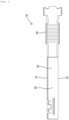
FIG. 1 is a right side view of a female terminal fitting of a first embodiment. -
FIG. 2 is a front view of the female terminal fitting. -
FIG. 3 is a left side view of the female terminal fitting. -
FIG. 4 is a plan view of the female terminal fitting. -
FIG. 5 is a bottom view of the female terminal fitting. -
FIG. 6 is a cross-sectional view taken along A-A inFIG. 2 . -
FIG. 7 is a cross-sectional view taken along B-B inFIG. 2 . -
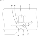
FIG. 8 is an enlarged view showing the periphery of a right rear opening inFIG. 1 in an enlarged manner. -
FIG. 9 is a cross-sectional view taken along C-C inFIG. 7 . -
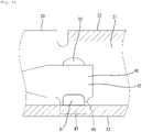
FIG. 10 is an enlarged view showing the periphery of a free end part of an elastic contact piece inFIG. 7 in an enlarged manner. -
FIG. 11 is an illustrative diagram illustrating a state in which a male tab is inserted in a main body part. -
FIG. 12 is a cross-sectional view seen from a back side of the female terminal fitting of a second embodiment. -
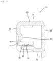
FIG. 13 is a cross-sectional view seen from a back side of the female terminal fitting of a third embodiment. -
FIG. 14 is a right side view of the periphery of a right rear opening in the female terminal fitting of the third embodiment. - Initially, embodiments of the present disclosure will be enumerated and described.
- A female terminal fitting of the present disclosure includes:
- (1) a tubular main body part and an elastic contact piece provided inside the main body part and deflectively deforming in a plate thickness direction, the main body part having a side plate part, the side plate being provided with a hole, an edge part of the hole being provided with a bent part bent to an inner side of the main body part, and the elastic contact piece having a projecting part that enters the hole and a region opposing the bent part in the plate thickness direction of the elastic contact piece together with the projecting part.
The elastic contact piece has a region opposing the bent part of the main body part in the plate thickness direction of the elastic contact piece together with the extension part. Thus, the engagement allowance of the main body part and the elastic contact piece can be increased. A state in which the elastic contact piece stably engages the main body part can thereby be realized. - (2) Preferably, the bent part is bent to the inner side of the main body part so as to incline relative to a plate surface of the side plate.
With this configuration, the engagement allowance with the bent part can be increased, by the amount that the bent part inclines relative to the plate surface of the side plate. - (3) Preferably, the bent part has a bending angle of 45 degrees or less with respect to the plate surface of the side plate.
With this configuration, the engagement allowance of the main body part and the elastic contact piece can be increased without excessively widening the interval between the bent part and the hole. - (4) Preferably, the bent part is bent avoiding an insertion path of a male tab within the main body part.
With this configuration, the male tab that is inserted in the main body part does not interfere with the bent part, and damage to the bent part and the male tab can be avoided. - (5) Preferably, the main body part is divided into an insertion side on which the insertion path is arranged and a non-insertion side, via the elastic contact piece, and the bent part is located on the insertion side of the main body part.
With this configuration, the freedom of design of the main body part can be increased. - (6) Preferably, the main body part has a regulating part that comes into contact with the elastic contact piece and regulates a displacement range of the elastic contact piece to less than or equal to a plate thickness of the elastic contact piece.
- With this configuration, by regulating the displacement range of the elastic contact piece to less than or equal to the plate thickness with the regulating part, the displacement amount of the elastic contact piece can be suppressed, as compared with the case where the displacement range is larger than the plate thickness. Thus, stress that occurs on the elastic contact piece when an external force is applied to the elastic contact piece (e.g., when vibration occurs during transportation) can be reduced, and damage to the elastic contact piece is more easily avoided.
- A first embodiment embodying a female terminal fitting of the present disclosure will be described with reference to
FIGS. 1 to 11 . In the first embodiment, with regard to the front and rear directions, leftward inFIGS. 1 ,4 to 8, 10 and 11 is frontward and rightward is rearward. With regard to the up and down directions, upward and downward as they appear inFIGS. 1 to 3 ,6 and8 to 11 . With regard to the left and right directions, rightward inFIG. 9 is leftward and leftward is rightward. - A female terminal fitting 10 of the first embodiment shown in
FIG. 1 is integrally formed by a process such as bending a conductive metal plate, and is connectable to a partner-side male terminal fitting 110 shown inFIG. 11 . As shown inFIG. 6 , the female terminal fitting 10 includes amain body part 20, anelastic contact piece 40 and awire connecting part 50. Thewire connecting part 50 has an open barrel shape, and a terminal part of an electrical wire is conductively connected by crimping. - As shown in
FIGS. 1 and2 , themain body part 20 has a rectangular tube shape that is hollow throughout in the front-rear direction. A male tab 120 (seeFIG. 11 ) of the male terminal fitting 110 is inserted into themain body part 20. Themain body part 20 includes abottom plate 21, a left side plate 22 (seeFIG. 3 ), aright side plate 23 and atop plate 24. Thebottom plate 21 is a plate that is elongated in the front-rear direction. As shown inFIG. 5 , thebottom plate 21 is provided with alance hole 21A. Thelance hole 21A is open in a rectangular shape across the entirety of thebottom plate 21 in the left-right direction. As shown inFIG. 6 , thebottom plate 21 is provided with aprotruding part 21B on the frontward side of thelance hole 21A. The protrudingpart 21B is formed by being hammered out from the downward side, for example. Theleft side plate 22 and theright side plate 23 respectively stand erect from the left and right edges of thebottom plate 21. - The
top plate 24 extends from the erect upper end of theright side plate 23 to theleft side plate 22 side in parallel with thebottom plate 21. Part of the left edge of thetop plate 24 contacts the upper end of theleft side plate 22 from the upper side. As shown inFIGS. 6 and7 , a portion of the left edge of thetop plate 24 that does not contact the upper end of theleft side plate 22 is provided with a frontside engaging plate 24A that extends downward along the inner surface of the left side plate 22 (so as to overlap therewith). - As shown in
FIG. 6 , atab receiving part 24B is formed in thetop plate 24 by being downwardly hammered out. A tab entry space (insertion path) 24C for themale tab 120 inserted into themain body part 20 from the front to enter is formed between the lower surface of thetab receiving part 24B and the upper surface of theelastic contact piece 40 described later. - As shown in
FIG. 3 , theleft side plate 22 is provided with aleft front opening 22A at a position on the front end part side. Theleft front opening 22A is provided with anextension piece 22B. Theextension piece 22B extends downward from an upper edge part of theleft front opening 22A. - As shown in
FIG. 1 , theright side plate 23 is respectively provided with aright front opening 25 and a right rear opening (hole) 26 at front and rear positions. Theright front opening 25 is provided at a position corresponding to the lower end of the frontside engaging plate 24A (position overlapping therewith in left-right direction). Theright front opening 25 has a rectangular shape. The rightrear opening 26 is provided at a position corresponding to asecond regulating part 32 described later (position overlapping therewith in left-right direction). The rightrear opening 26 has a rectangular shape. - As shown in
FIG. 8 , themain body part 20 is provided with a first regulating part (bent part) 31 and the second regulatingpart 32. The first regulatingpart 31 and the second regulatingpart 32 come in contact with theelastic contact piece 40 and regulate a displacement range of afree end part 42 side of theelastic contact piece 40. The first regulatingpart 31 is provided on an erect side (edge part on upper side) of the rightrear opening 26. The first regulatingpart 31 is a rectangular plate-shaped protruding piece protruding from the edge part on the upper side of the rightrear opening 26. As shown inFIG. 9 , the first regulatingpart 31 is bent to the inner side of themain body part 20. The first regulatingpart 31 is bent to the inner side of themain body part 20 so as incline relative to the plate surface of theright side plate 23. The first regulatingpart 31 has a bending angle θ of 45 degrees or less with respect to the plate surface of theright side plate 23, and preferably 30 degrees, for example. - As shown in
FIG. 9 , the first regulatingpart 31 is bent avoiding the insertion path (tab entry space 24C) of themale tab 120 within themain body part 20. That is, the first regulatingpart 31 is located on the right side away from thetab entry space 24C. - As shown in
FIG. 9 , themain body part 20 is divided into aninsertion side 20A of themale tab 120 and anon-insertion side 20B of themale tab 120, via theelastic contact piece 40. Thetab entry space 24C is arranged on theinsertion side 20A. In themain body part 20, the portion on the upward side of theelastic contact piece 40 is theinsertion side 20A, and the portion on the downward side of theelastic contact piece 40 is thenon-insertion side 20B. The first regulatingpart 31 is located on theinsertion side 20A of themain body part 20. - As shown in
FIG. 8 , the second regulatingpart 32 is provided at a position on an opposite side (downward side) to the first regulatingpart 31 across thefree end part 42 of theelastic contact piece 40. As shown inFIG. 6 , the second regulatingpart 32 is provided on thebottom plate 21. Thesecond regulating part 32 is provided at a position rearward of thelance hole 21A in thebottom plate 21. Thesecond regulating part 32 supports theelastic contact piece 40 from below. Thesecond regulating part 32 is formed to protrude by being hammered out from the downward side, for example. Thesecond regulating part 32 comes in contact with thefree end part 42 of theelastic contact piece 40 that is elastically deflected due to interference with themale tab 120, and supports theelastic contact piece 40. - As shown in
FIG. 6 , theelastic contact piece 40 is housed within themain body part 20. Theelastic contact piece 40 contacts the male tab 120 (seeFIG. 11 ) of the male terminal fitting 110 inserted in themain body part 20. As shown inFIG. 6 , theelastic contact piece 40 doubles back from the front end of thebottom plate 21 and extends rearward in a cantilever manner. Theelastic contact piece 40 has a shape elongated in the front-rear direction, extending from a support point part (bent part) 41 to thefree end part 42. Thesupport point part 41 has a semicircular arc shape continuous with the front end of thebottom plate 21. Theelastic contact piece 40 has anextension part 44. Theextension part 44 extends rearward from thesupport point part 41. Theextension part 44 is provided with afront inclining part 44A and arear inclining part 44B. Thefront inclining part 44A extends rearward diagonally upward from the upper end of thesupport point part 41. Therear inclining part 44B extends rearward diagonally downward from the rear end of thefront inclining part 44A. - In a free state (natural state) in which the
elastic contact piece 40 is not elastically deflected, thefree end part 42 is in a non-contact position upward of thebottom plate 21. Thus, theelastic contact piece 40 is in a state of being supported in a cantilever manner at the front end thereof by thebottom plate 21. Theelastic contact piece 40 can be elastically deformed in the up-down direction while elastically deflecting mainly at thesupport point part 41, with thesupport point part 41 as the support point. Thefree end part 42 side of theelastic contact piece 40 displaces in the plate thickness direction of theelastic contact piece 40. Theelastic contact piece 40, when elastically deflected downward, will be supported at both the front and rear ends, due to thefree end part 42 coming in contact with the second regulatingpart 32 of thebottom plate 21. - As shown in
FIG. 6 , the rear end (highest portion) of thefront inclining part 44A is provided with acontact point part 45 in a form upwardly hammered out into a dome shape. Thecontact point part 45 contacts the male tab 120 (seeFIG. 11 ). The distance from thesupport point part 41 to thecontact point part 45 is smaller than the distance from thecontact point part 45 to thefree end part 42. - As shown in
FIG. 7 , a pair of frontside projecting parts 46 is provided on left and right edge parts of the front end part side of theelastic contact piece 40. The frontside projecting parts 46 are in a form projecting in a flush manner outwardly in the width direction. The frontside projecting parts 46 are arranged in the vicinity of thecontact point part 45, that is, in a position slightly frontward of thecontact point part 45. As shown inFIG. 3 , the frontside projecting part 46 on the left side is positioned so as to correspond to theleft front opening 22A in the front-rear direction. In the free state (natural state) in which theelastic contact piece 40 is not elastically deflected, the upper surface of the frontside projecting part 46 on the left side is in a non-contact position slightly downward of the lower edge part of theextension piece 22B. The frontside projecting part 46 on the right side is positioned so as to correspond to theright front opening 25 in the front-rear direction. In the free state (natural state) in which theelastic contact piece 40 is not elastically deflected, the upper surface of the frontside projecting part 46 on the right side is in a non-contact position slightly downward of the lower edge part of theright front opening 25. - As shown in
FIGS. 7 and10 , a rearside projecting part 47 is provided on the right side edge part of the rear end part side of theelastic contact piece 40. The rearside projecting part 47 is in a form projecting in a flush manner outwardly in the width direction. The rearside projecting part 47 projects in the width direction (right direction) from thefree end part 42 side. The rearside projecting part 47 constitutes part of thefree end part 42. The rearside projecting part 47 is positioned so as to correspond the rightrear opening 26 in the front-rear direction. The rearside projecting part 47 is located within the rightrear opening 26. In the free state (natural state) in which theelastic contact piece 40 is not elastically deflected, the upper surface of the rearside projecting part 47 is in a non-contact position slightly downward of the first regulatingpart 31. At this time, the distance between the upper surface of the rearside projecting part 47 and the first regulatingpart 31 is smaller than the plate thickness of theelastic contact piece 40. The lower surface of thefree end part 42 including the rearside projecting part 47 on the right side is in close proximity to the second regulatingpart 32. Note that the lower surface of thefree end part 42 may contact the second regulatingpart 32. - The first regulating
part 31 and the second regulatingpart 32 come in contact with theelastic contact piece 40 and regulate the displacement range of thefree end part 42 side of theelastic contact piece 40 to less than or equal to the plate thickness of theelastic contact piece 40. That is, thefree end part 42 of theelastic contact piece 40 displaces by a distance less than or equal to the plate thickness of theelastic contact piece 40 when changing between the state of coming in contact with the first regulatingpart 31 and the state of coming in contact with the second regulating part 32 (when displacing in up-down direction). - As shown in
FIG. 8 , the distance between a center position of the upper surface of the rearside projecting part 47 in the front-rear direction and the lower end of the first regulatingpart 31 is L1. The distance between a center position of the lower surface of the rearside projecting part 47 in the front-rear direction and the upper end of the second regulatingpart 32 is L2. The sum of L1 and L2 is smaller than a plate thickness L3 of theelastic contact piece 40. When theelastic contact piece 40 is in the free state (natural state), L1 is larger than L2. - As shown in
FIG. 10 , theelastic contact piece 40 has a region (extended region) 48 opposing the first regulatingpart 31 in the plate thickness direction of theelastic contact piece 40 together with the rearside projecting part 47. Theregion 48 of theelastic contact piece 40 is a portion that overlaps with the first regulatingpart 31 in the up-down direction. Theregion 48 is a portion that is long in the front-rear direction and adjacent on the right side to the rearside projecting part 47. The length of theregion 48 in the front-rear direction is about the same as the length of the first regulatingpart 31 in the front-rear direction. In this way, due to the first regulatingpart 31 being bent, the engagement allowance of themain body part 20 and theelastic contact piece 40 can be increased by the size of theregion 48, as compared with a configuration in which the first regulatingpart 31 is not bent. - When connecting the male terminal fitting 110 to the female terminal fitting 10, the
male tab 120 is inserted into thetab entry space 24C of themain body part 20 from the frontward side. Themale tab 120 inserted in thetab entry space 24C is elastically sandwiched between thetab receiving part 24B and thecontact point part 45 while elastically deflecting theelastic contact piece 40. Themale tab 120 and themain body part 20 are conductively connected due to the elastic restoring force of theelastic contact piece 40. - As described above, in the female terminal fitting 10 of the present disclosure, the
elastic contact piece 40 has theregion 48 opposing the first regulatingpart 31 of themain body part 20 in the plate thickness direction of theelastic contact piece 40 together with the rearside projecting part 47. Thus, the engagement allowance of themain body part 20 and theelastic contact piece 40 can be increased. A state in which theelastic contact piece 40 stably engages themain body part 20 can thereby be realized. - In the female terminal fitting 10 of the present disclosure, the first regulating
part 31 is bent to the inner side of themain body part 20 so as to incline relative to the plate surface of theright side plate 23. With this configuration, the engagement allowance with the first regulatingpart 31 can be increased by the amount that the first regulatingpart 31 inclines relative to the plate surface of theright side plate 23. - In the female terminal fitting 10 of the present disclosure, the first regulating
part 31 has a bending angle of 45 degrees or less with respect to the plate surface of theright side plate 23. With this configuration, the engagement allowance of themain body part 20 and theelastic contact piece 40 can be increased, without excessively widening the interval between the first regulatingpart 31 and the rightrear opening 26. - In the female terminal fitting 10 of the present disclosure, the first regulating
part 31 is bent avoiding thetab entry space 24C into which themale tab 120 is inserted within themain body part 20. With this configuration, themale tab 120 that is inserted within themain body part 20 does not interfere with the first regulatingpart 31, and damage to the first regulatingpart 31 and themale tab 120 can be avoided. - In the female terminal fitting 10 of the present disclosure, the
main body part 20 is divided into theinsertion side 20A on which thetab entry space 24C is arranged and thenon-insertion side 20B, via theelastic contact piece 40, and the first regulatingpart 31 is located on theinsertion side 20A of themain body part 20. With this configuration, the freedom of design of themain body part 20 can be increased. - The female terminal fitting 10 of the present disclosure is able to suppress the displacement amount of the
elastic contact piece 40, as compared with the case where the displacement range is larger than the plate thickness, by regulating the displacement range of theelastic contact piece 40 to less than or equal to the plate thickness with the first regulatingpart 31 and the second regulatingpart 32. Thus, stress that occurs on theelastic contact piece 40 when an external force is applied to the elastic contact piece 40 (e.g., when vibration occurs during transportation) can be reduced, and damage to theelastic contact piece 40 is more easily avoided. -
FIG. 12 is a diagram illustrating a female terminal fitting 210 of a second embodiment. In the second embodiment, the configuration of the first regulating part differs from the first embodiment. The remaining configuration is the same as the first embodiment, and detailed description thereof will be omitted. - As shown in
FIG. 12 , in the female terminal fitting 210, a left side portion of the distal end of afirst regulating part 231 is provided with abeveled part 231A. Thebeveled part 231A is formed by faceting the corner part on the left side of the distal end of the first regulatingpart 231. -
FIGS. 13 and14 are diagrams illustrating a female terminal fitting 310 of a third embodiment. In the third embodiment, the configuration of the first regulating part differs from the first embodiment. The remaining configuration is the same as the first embodiment, and detailed description thereof will be omitted. - As shown in
FIGS. 13 and14 , afirst regulating part 331 formed by being hammered out is provided in the female terminal fitting 310. Thefirst regulating part 331 is formed by part of the right side plate 23 (upper edge part of right rear opening 26) being inwardly hammered out. Unlike the first embodiment, there are no slits front and rear of the first regulatingpart 331, and the first regulatingpart 331 and theright side plate 23 are continuous in the front-rear direction. - The present invention is not limited to the first to third embodiments described above with reference to the drawings, and is defined by the claims. All changes that come within the meaning and range of equivalency of the claims are intended to be embraced in the invention, and embodiments such as the following are also intended to be embraced therein.
- In the above first to third embodiments, configurations in which the displacement range of the rear
side projecting part 47 is regulated by thefirst regulating parts main body part 20, but may also be provided on the left edge part side of themain body part 20. That is, a left side edge part of the rear end part side of theelastic contact piece 40 may be provided with a projecting part similar to the rearside projecting part 47, and an opening similar to the rightrear opening 26 may be provided at a position on the rear end part side of theleft side plate 22. -
- 10, 210, 310
- Female terminal fitting
- 20
- Main body part
- 20A
- Insertion side
- 20B
- Non-insertion side
- 21
- Bottom plate
- 21A
- Lance hole
- 21B
- Protruding part
- 22
- Left side plate
- 22A
- Left front opening
- 22B
- Extension piece
- 23
- Right side plate (side plate)
- 24
- Top plate
- 24A
- Front side engaging plate
- 24B
- Tab receiving part
- 24C
- Tab entry space (insertion path)
- 25
- Right front opening
- 26
- Right rear opening (hole)
- 31, 231, 331
- First regulating part (bent part, regulating part)
- 32
- Second regulating part (regulating part)
- 40
- Elastic contact piece
- 41
- Support point part (bent part)
- 42
- Free end part
- 44
- Extension part
- 44A
- Front inclining part
- 44B
- Rear inclining part
- 45
- Contact point part
- 46
- Front side projecting part
- 47
- Rear side projecting part (projecting part)
- 48
- Region (extended region)
- 50
- Wire connecting part
- 110
- Male terminal fitting
- 120
- Male tab
- 231A
- Beveled part
Claims (6)
- A female terminal fitting comprising:a tubular main body part; andan elastic contact piece provided inside the main body part and deflectively deforming in a plate thickness direction,wherein the main body part has a side plate,the side plate is provided with a hole,an edge part of the hole is provided with a bent part bent to an inner side of the main body part, andthe elastic contact piece has:a projecting part that enters the hole; anda region opposing the bent part in the plate thickness direction of the elastic contact piece together with the projecting part.
- The female terminal fitting according to claim 1,
wherein the bent part is bent to the inner side of the main body part so as to incline relative to a plate surface of the side plate. - The female terminal fitting according to claim 2,
wherein the bent part has a bending angle of 45 degrees or less with respect to the plate surface of the side plate. - The female terminal fitting according to any one of claims 1 to 3,
wherein the bent part is bent avoiding an insertion path of a male tab within the main body part. - The female terminal fitting according to claim 4,wherein the main body part is divided into an insertion side on which the insertion path is arranged and a non-insertion side, via the elastic contact piece, andthe bent part is located on the insertion side of the main body part.
- The female terminal fitting according to any one of claims 1 to 5,
wherein the main body part has a regulating part that comes into contact with the elastic contact piece and regulates a displacement range of the elastic contact piece to less than or equal to a plate thickness of the elastic contact piece.
Applications Claiming Priority (2)
| Application Number | Priority Date | Filing Date | Title |
|---|---|---|---|
| JP2020080460A JP7396188B2 (en) | 2020-04-30 | 2020-04-30 | Female terminal fitting |
| PCT/JP2021/012158 WO2021220675A1 (en) | 2020-04-30 | 2021-03-24 | Female terminal fitting |
Publications (2)
| Publication Number | Publication Date |
|---|---|
| EP4145641A1 true EP4145641A1 (en) | 2023-03-08 |
| EP4145641A4 EP4145641A4 (en) | 2023-10-25 |
Family
ID=78279891
Family Applications (1)
| Application Number | Title | Priority Date | Filing Date |
|---|---|---|---|
| EP21794455.2A Pending EP4145641A4 (en) | 2020-04-30 | 2021-03-24 | Female terminal fitting |
Country Status (5)
| Country | Link |
|---|---|
| US (1) | US12355175B2 (en) |
| EP (1) | EP4145641A4 (en) |
| JP (1) | JP7396188B2 (en) |
| CN (1) | CN115443582A (en) |
| WO (1) | WO2021220675A1 (en) |
Family Cites Families (32)
| Publication number | Priority date | Publication date | Assignee | Title |
|---|---|---|---|---|
| JPS6174967U (en) | 1984-10-22 | 1986-05-21 | ||
| US5217382A (en) * | 1992-06-05 | 1993-06-08 | Interlock Corporation | Electric receptacle with shape memory spring member |
| JP3285101B2 (en) * | 1993-01-21 | 2002-05-27 | 矢崎総業株式会社 | Female terminal |
| JP2988608B2 (en) * | 1994-01-31 | 1999-12-13 | 矢崎総業株式会社 | Female terminal and method of manufacturing the same |
| JP3119418B2 (en) * | 1994-04-20 | 2000-12-18 | 矢崎総業株式会社 | Terminal for waterproof connector |
| US5810627A (en) * | 1996-01-11 | 1998-09-22 | Molex Incorporated | Female electrical terminal |
| EP0932917B1 (en) * | 1996-10-17 | 2000-05-24 | The Whitaker Corporation | Electrical connector having a housing and an electrical contact |
| US6196884B1 (en) * | 1997-07-22 | 2001-03-06 | Harness System Technologies Research, Ltd. | Female metal terminal that stably connects with male metal terminal |
| US6056604A (en) * | 1998-07-29 | 2000-05-02 | Framatome Connectors Interlock, Inc. | Electrical receptacle terminal with a contact spring biased against a side of the receptacle without spreading a seam in the side of the receptacle |
| US6247975B1 (en) * | 1998-12-14 | 2001-06-19 | Framatome Connectors Interlock, Inc. | Multi-piece electrical receptacle terminal |
| JP3544133B2 (en) * | 1999-01-20 | 2004-07-21 | 住友電装株式会社 | Female terminal fitting |
| DE10012262C2 (en) * | 1999-03-16 | 2002-10-24 | Sumitomo Wiring Systems | female contact |
| AU5157800A (en) * | 1999-05-28 | 2000-12-18 | Whitaker Corporation, The | Electrical contact receptacle terminal to mate with round and rectangular pins |
| JP3473536B2 (en) | 2000-01-28 | 2003-12-08 | 住友電装株式会社 | Female terminal fitting |
| GB0016790D0 (en) * | 2000-07-07 | 2000-08-30 | Tyco Electronics Amp Es Sa | Electrical connector |
| JP3576488B2 (en) * | 2000-12-18 | 2004-10-13 | 日本圧着端子製造株式会社 | Female terminal |
| JP2005166594A (en) * | 2003-12-05 | 2005-06-23 | Auto Network Gijutsu Kenkyusho:Kk | Female terminal structure |
| JP2006216316A (en) | 2005-02-02 | 2006-08-17 | Sumitomo Wiring Syst Ltd | Terminal fitting |
| JP4442449B2 (en) * | 2005-02-02 | 2010-03-31 | 住友電装株式会社 | Terminal fitting |
| JP4207007B2 (en) | 2005-02-02 | 2009-01-14 | 住友電装株式会社 | Terminal fitting |
| US7223135B2 (en) * | 2005-02-02 | 2007-05-29 | Sumitomo Wiring Systems, Ltd. | Terminal fitting and a connector provided therewith |
| US7252562B1 (en) * | 2006-08-11 | 2007-08-07 | J.S.T. Corporation | Electrical female terminal and female electrical connector |
| US7530859B2 (en) * | 2007-05-08 | 2009-05-12 | Tyco Electronics Corporation | Electrical contact |
| JP2011154944A (en) * | 2010-01-28 | 2011-08-11 | Yazaki Corp | Female terminal fitting |
| JP2011216435A (en) * | 2010-04-02 | 2011-10-27 | Sumitomo Wiring Syst Ltd | Terminal fitting |
| JP5482556B2 (en) | 2010-08-06 | 2014-05-07 | 住友電装株式会社 | Terminal fitting |
| JP5482557B2 (en) * | 2010-08-06 | 2014-05-07 | 住友電装株式会社 | Terminal fittings and connectors |
| JP5682520B2 (en) * | 2011-09-14 | 2015-03-11 | 住友電装株式会社 | Terminal fitting |
| JP6342608B2 (en) * | 2012-12-04 | 2018-06-13 | 矢崎総業株式会社 | Female terminal |
| JP2014160544A (en) | 2013-02-19 | 2014-09-04 | Sumitomo Wiring Syst Ltd | Female terminal fitting |
| JP6780571B2 (en) * | 2017-04-10 | 2020-11-04 | 住友電装株式会社 | Terminal bracket |
| JP2020042914A (en) * | 2018-09-06 | 2020-03-19 | 矢崎総業株式会社 | Terminal fitting |
-
2020
- 2020-04-30 JP JP2020080460A patent/JP7396188B2/en active Active
-
2021
- 2021-03-24 US US17/921,773 patent/US12355175B2/en active Active
- 2021-03-24 EP EP21794455.2A patent/EP4145641A4/en active Pending
- 2021-03-24 WO PCT/JP2021/012158 patent/WO2021220675A1/en not_active Ceased
- 2021-03-24 CN CN202180030680.XA patent/CN115443582A/en active Pending
Also Published As
| Publication number | Publication date |
|---|---|
| US20230170640A1 (en) | 2023-06-01 |
| US12355175B2 (en) | 2025-07-08 |
| WO2021220675A1 (en) | 2021-11-04 |
| JP2021174750A (en) | 2021-11-01 |
| EP4145641A4 (en) | 2023-10-25 |
| JP7396188B2 (en) | 2023-12-12 |
| CN115443582A (en) | 2022-12-06 |
Similar Documents
| Publication | Publication Date | Title |
|---|---|---|
| KR102509668B1 (en) | Electric connector for circuit substrate | |
| US7938695B2 (en) | Terminal fitting | |
| EP2363921B1 (en) | Terminal fitting | |
| EP2571105B1 (en) | Terminal fitting and connector provided therewith | |
| US6174208B1 (en) | Female terminal for a connector and a housing therefor | |
| EP2416452B1 (en) | Terminal fitting | |
| US9281575B2 (en) | Terminal | |
| US20160006143A1 (en) | Female terminal fitting | |
| EP2571104A1 (en) | Terminal fitting | |
| CN1815816B (en) | A terminal fitting, connector provided therewith and method of forming a terminal fitting | |
| US20200203869A1 (en) | Female terminal | |
| EP2056408A2 (en) | An electrical terminal fitting and forming method therefor | |
| US10944217B2 (en) | Terminal fitting | |
| US12355175B2 (en) | Female terminal fitting with elastic contact piece engageable with body part | |
| US12418127B2 (en) | Female terminal fitting with durable elastic contact piece | |
| US11349242B2 (en) | Male wire terminal and male wire connector | |
| US11158986B2 (en) | Shorting terminal and connector | |
| US20210175652A1 (en) | Terminal fitting, method of producing the same, and connector | |
| US9356375B2 (en) | Male terminal fitting | |
| JP2017208166A (en) | Terminal | |
| EP4471994A1 (en) | Terminal and connector | |
| JP7435362B2 (en) | Terminal fittings and chain terminals | |
| EP2575215B1 (en) | Terminal fitting | |
| JP2013016359A (en) | Terminal fitting | |
| US20250253550A1 (en) | Pre-crimped terminal |
Legal Events
| Date | Code | Title | Description |
|---|---|---|---|
| STAA | Information on the status of an ep patent application or granted ep patent |
Free format text: STATUS: THE INTERNATIONAL PUBLICATION HAS BEEN MADE |
|
| PUAI | Public reference made under article 153(3) epc to a published international application that has entered the european phase |
Free format text: ORIGINAL CODE: 0009012 |
|
| STAA | Information on the status of an ep patent application or granted ep patent |
Free format text: STATUS: REQUEST FOR EXAMINATION WAS MADE |
|
| 17P | Request for examination filed |
Effective date: 20221020 |
|
| AK | Designated contracting states |
Kind code of ref document: A1 Designated state(s): AL AT BE BG CH CY CZ DE DK EE ES FI FR GB GR HR HU IE IS IT LI LT LU LV MC MK MT NL NO PL PT RO RS SE SI SK SM TR |
|
| DAV | Request for validation of the european patent (deleted) | ||
| DAX | Request for extension of the european patent (deleted) | ||
| A4 | Supplementary search report drawn up and despatched |
Effective date: 20230926 |
|
| RIC1 | Information provided on ipc code assigned before grant |
Ipc: H01R 13/193 20060101ALI20230921BHEP Ipc: H01R 4/18 20060101ALI20230921BHEP Ipc: H01R 13/11 20060101AFI20230921BHEP |
|
| STAA | Information on the status of an ep patent application or granted ep patent |
Free format text: STATUS: EXAMINATION IS IN PROGRESS |
|
| 17Q | First examination report despatched |
Effective date: 20251001 |