EP4145407A1 - Vehicles, systems and methods for determining an occupancy map of a vicinity of a vehicle - Google Patents
Vehicles, systems and methods for determining an occupancy map of a vicinity of a vehicle Download PDFInfo
- Publication number
- EP4145407A1 EP4145407A1 EP21190812.4A EP21190812A EP4145407A1 EP 4145407 A1 EP4145407 A1 EP 4145407A1 EP 21190812 A EP21190812 A EP 21190812A EP 4145407 A1 EP4145407 A1 EP 4145407A1
- Authority
- EP
- European Patent Office
- Prior art keywords
- expectation area
- object detection
- implemented method
- data acquisition
- expectation
- Prior art date
- Legal status (The legal status is an assumption and is not a legal conclusion. Google has not performed a legal analysis and makes no representation as to the accuracy of the status listed.)
- Pending
Links
Images


Classifications
-
- G—PHYSICS
- G01—MEASURING; TESTING
- G01C—MEASURING DISTANCES, LEVELS OR BEARINGS; SURVEYING; NAVIGATION; GYROSCOPIC INSTRUMENTS; PHOTOGRAMMETRY OR VIDEOGRAMMETRY
- G01C21/00—Navigation; Navigational instruments not provided for in groups G01C1/00 - G01C19/00
- G01C21/38—Electronic maps specially adapted for navigation; Updating thereof
- G01C21/3804—Creation or updating of map data
-
- G—PHYSICS
- G06—COMPUTING; CALCULATING OR COUNTING
- G06F—ELECTRIC DIGITAL DATA PROCESSING
- G06F18/00—Pattern recognition
- G06F18/20—Analysing
- G06F18/22—Matching criteria, e.g. proximity measures
-
- G—PHYSICS
- G06—COMPUTING; CALCULATING OR COUNTING
- G06V—IMAGE OR VIDEO RECOGNITION OR UNDERSTANDING
- G06V10/00—Arrangements for image or video recognition or understanding
- G06V10/98—Detection or correction of errors, e.g. by rescanning the pattern or by human intervention; Evaluation of the quality of the acquired patterns
-
- G—PHYSICS
- G06—COMPUTING; CALCULATING OR COUNTING
- G06V—IMAGE OR VIDEO RECOGNITION OR UNDERSTANDING
- G06V20/00—Scenes; Scene-specific elements
- G06V20/50—Context or environment of the image
- G06V20/56—Context or environment of the image exterior to a vehicle by using sensors mounted on the vehicle
- G06V20/58—Recognition of moving objects or obstacles, e.g. vehicles or pedestrians; Recognition of traffic objects, e.g. traffic signs, traffic lights or roads
Definitions
- the present disclosure relates to vehicles, systems and methods for determining an occupancy map in the vicinity of a vehicle.
- An occupancy map also referred to as occupancy grid or occupancy map grid, is a map of cells containing information of the cell being occupied by some kind of object.
- the cells may have a fixed width, length and height.
- Occupancy maps are widely used in Advanced Driver Assistance Systems (ADAS) and autonomous driving applications, because an occupancy map can be interpreted as a map of obstacles around the vehicle.
- Each occupied cell may represent a non drivable area.
- An inverted occupancy map can be interpreted as a free space map showing the drivable regions.
- Moving objects like other vehicles should not form entries of an occupancy map.
- a reliable classification of object detections as "moving" or "stationary” is difficult.
- slow moving targets like pedestrians or temporarily stationary objects like vehicles stopping at traffic lights can be falsely identified as obstacles, for example due to inaccuracies in measurement (for example Doppler error) and computation.
- Such falsely identified obstacles result in ghost targets or traces in the occupancy map and impair the representation of the drivable space.
- the present disclosure provides a computer implemented method, a computer system and a non-transitory computer readable medium according to the independent claims. Embodiments are given in the dependent claims, the description and the drawings.
- the present disclosure is directed at a computer implemented method for determining an occupancy map of a vicinity of a vehicle, the method comprising the following steps carried out by computer hardware components:
- an expectation area extending around the respective object is created.
- the expectation area is repositioned to follow the potentially present object. If the object disappears in later sensor data, the corresponding entry in the occupancy map is removed, because it is assumed that the object has moved out of the expectation area. The repositioning of the expectation area ensures that the focus is kept on the potential object.
- the sensor system may comprise a radar sensor and/or a lidar sensor.
- the first and the second data acquisition process may correspond to successive scans or frames of the radar and/or lidar sensor.
- an object detection corresponds to a detected surface spot of an object present in the vicinity of the vehicle.
- the position of the expectation area may be adjusted in step (v) such that, after the adjustment, a centre of the expectation area is close to all accumulated occupancy probabilities.
- the adjustment could be alternatively such that the object detection of the subsequent second data acquisition process is centrally positioned in the adjusted expectation area. If the difference between the position of the object detection of the first data acquisition process and the position of the object detection of the second data acquisition process is zero, no adjustment is necessary.
- step (vi) any object detections or entries located in the expectation area may be removed from the occupancy map. Further, the step (iv) may be carried out for each object detection of the first data acquisition process.
- the method may further include one or more of the following features:
- the object detections may be respectively determined based on an occupancy probability which is updated after each data acquisition process.
- the occupancy probability may be defined as a log odds ratio.
- Determining object detections in step (ii) may comprise determining peaks of the log odds ratio. It may be determined that no object detection can be determined within the expectation area if no occupancy probability in the expectation area exceeds a predefined detection threshold.
- the stop criterion may be defined based on a cumulative occupancy probability of the expectation area. The stop criterion may be fulfilled if the cumulative occupancy probability of the expectation area exceeds a predefined trace threshold.
- Removing the at least one object detection of the expectation area in step (vi) may comprise setting the occupancy probabilities of the expectation area to zero.
- the object detections determined in step (ii) may be classified as either moving or stationary. Only object detections classified as stationary may be overlaid in the spatial representation of the vicinity of the vehicle in step (iii).
- the at least one object detection which has been removed from the occupancy map in step (vi) may be stored in a trace map separate from the occupancy map.
- a sanity check may be performed if no object detection can be determined in the expectation area for a predetermined number of successive data acquisition processes after the first data acquisition process and the object detection may be only removed from the occupancy map if the result of the sanity check is positive.
- the sanity check may comprise an occlusion check and the result of the sanity check may be negative if the expectation area is occluded by another object detection or another expectation area.
- the object detections are respectively determined based on an occupancy probability which is updated after each data acquisition process.
- the occupancy map may comprise a plurality of cells, wherein an occupancy probability is assigned to each of the cells.
- the occupancy map may be represented by a matrix (for a two-dimensional occupancy map) or a tensor (for a three-dimensional occupancy map), wherein each of the two dimensions of the matrix (or each of the three dimensions of the tensor) corresponds to a dimension in space.
- An entry of a cell of the matrix or the tensor at a specific position may correspond to information whether or not an object is potentially present at that location and may be presented by a Boolean value such as "true” for "object present” and "false” for "object not present”.
- the probability may be indicated by a number between 0 and 1 or between 0% and 100%.
- the occupancy probability is defined as a log odds ratio, i. e. as the logarithm, for example the natural logarithm, of the ratio between the probability of the cell being occupied to the probability of the cell not being occupied.
- the log odds ratio can be easily updated with new data.
- determining object detections in step (ii) comprises determining peaks of the log odds ratio.
- an object detection may be assumed to be present whenever a log odds peak value occurs in an update cycle.
- a peak value of the updated log odds ratio corresponds to an intensity peak of the current sensor output.
- no object detection can be determined in the expectation area if no occupancy probability in the expectation area exceeds a predefined detection threshold, i. e. if all occupancy probabilities of the cells of the expectation area respectively don't exceed the predefined detection threshold.
- the detection threshold may be 0.5.
- a reset counter may be incremented when no object detection can be determined in the expectation area, i. e. when no log odds ratio update is found.
- the step (vi) includes checking, for each data acquisition process, if a log odds ratio of the expectation area exceeds a predefined detection threshold. For example, once the expectation area has been defined, it may be checked for each subsequent data acquisition process, if the following expectation criterion is fulfilled: ⁇ scan log odds mi > 0.5 ⁇ expectation area , wherein scan refers to a data acquisition process and 0.5 is the detection threshold.
- the detection threshold may be selected in dependence of the velocity of the host vehicle. For example, the detection threshold may be high for a slow velocity and low for a high velocity.
- the stop criterion is defined based on a cumulative occupancy probability of the expectation area.
- the cumulative occupancy probability of the expectation area may be the sum of probabilities of all cells of the expectation area. I. e. if an expectation area is overfilled with high probability entries due to traces of a moving target, the repositioning is stopped. It has turned out that such a stop criterion enables a reliable removal of slow moving targets such as pedestrians from the occupancy map.
- the stop criterion is fulfilled if the cumulative occupancy probability of the expectation area exceeds a predefined threshold.
- stop criterion It may be checked if the stop criterion is fulfilled by summing up all object detections that are inside the expectation area and checking if the determined sum exceeds a predefined threshold. For example, it may be checked if the following stop criterion is fulfilled: ⁇ expectation area log odds > P threshold , wherein P threshold is the predefined threshold related to the stop criterion.
- P threshold is the predefined threshold related to the stop criterion.
- An exemplary value for P threshold is 12. For highly sensitive radar systems, the value may be smaller and vice versa.
- removing the at least one object detection of the expectation area in step (vi) comprises setting the occupancy probabilities of the expectation area, i. e. of all cells of the expectation area, to zero.
- undesired ghost entries, traces and the like are deleted.
- the object detections determined in step (ii) are classified as either moving or stationary and only object detections classified as stationary are overlaid in the spatial representation of the vicinity of the vehicle in step (iii). Due to inaccuracies of the classifier, such object detections may in fact correspond to moving objects, in particular to slowly moving objects or to temporarily moving objects. Such entries of the occupancy map may be subsequently removed from the occupancy map by a method as described herein.
- the at least one object detection which has been removed from the occupancy map in step (vi) is stored in a trace map separate from the occupancy map.
- a trace map may be used, for example, for a selective tracking of slowly moving pedestrians by means of a tracker and/or for a training of a machine learning algorithm able to identify pedestrians.
- a sanity check is performed if no object detection can be determined in the expectation area for a predetermined number of successive data acquisition processes after the first data acquisition process and the object detection is only removed from the occupancy map if the result of the sanity check is positive. Due to the complexity of the environment, there is a certain risk that no updated object detection is found in an expectation area despite an actual presence of an object. The sanity check avoids false removals of entries from the occupancy map.
- the sanity check comprises an occlusion check and the result of the sanity check is negative if the expectation area is occluded by another object detection or another expectation area. If an area is located behind a newly detected object from the perspective of the corresponding sensor, objects actually present in that area can't be detected due to occlusion.
- the sanity check provides for a keeping of information related to the occluded area.
- step (i) the distance of the object detection to a previously defined expectation area is determined and a further expectation area is only defined if the determined distance exceeds a predefined distance threshold. It has been found that such a measure can control an area overlap to be minimal in order to not create unnecessary expectation areas.
- the present disclosure is directed at a computer system, said computer system being configured to carry out several or all steps of the computer implemented method described herein.
- the computer system may comprise a processing unit, at least one memory unit and at least one non-transitory data storage.
- the non-transitory data storage and/or the memory unit may comprise a computer program for instructing the computer to perform several or all steps or aspects of the computer implemented method described herein.
- the present disclosure is directed at a vehicle comprising a computer system as described herein and the sensor system.
- the sensor system may comprise several short range radar sensors and at least one medium range radar sensor.
- the present disclosure is directed at a non-transitory computer readable medium comprising instructions for carrying out several or all steps or aspects of the computer implemented method described herein.
- the computer readable medium may be configured as: an optical medium, such as a compact disc (CD) or a digital versatile disk (DVD); a magnetic medium, such as a hard disk drive (HDD); a solid state drive (SSD); a read only memory (ROM), such as a flash memory; or the like.
- the computer readable medium may be configured as a data storage that is accessible via a data connection, such as an internet connection.
- the computer readable medium may, for example, be an online data repository or a cloud storage.
- the present disclosure is also directed at a computer program for instructing a computer to perform several or all steps or aspects of the computer implemented method described herein.
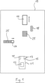
- Fig. 1 depicts, in a top view, a motor vehicle or host vehicle 11 including a computer system 12 and a sensor system 13 connected to the computer system 12.
- the sensor system 13 includes a plurality of sensors 15 configured to scan the vicinity of the host vehicle 11 for objects such as other vehicles 16, pedestrians 17 or stationary objects like traffic lights 18.
- the sensors 15 of the sensor system 13 may be radar (radio detection and ranging) sensors, lidar (light detection and ranging) sensors and/or time-of-flight cameras.
- the computer system 12 receives data from the sensors 15 and provides an "advanced driver assistance" functionality or an autonomous driving functionality based on an evaluation of the received data.
- an occupancy map 19 of the vicinity of the host vehicle 11 may be determined by accumulating readings from the sensors 15 of the sensor system 13 and transforming the accumulated sensor readings to probabilities over time.
- the occupancy map 19 may include a two-dimensional or three-dimensional grid of cells (not shown), wherein an occupancy probability is assigned to each of the cells, as is known in the art.
- the occupancy probability may be updated after each data acquisition process, i. e. after each frame or scan of the sensors 15.
- the occupancy probability may be indicated as a log odds ratio.
- the occupancy map 19 shows obstacles in form of stationary objects and thus also shows the drivable space, i. e. the space which is free from obstacles. Generally, only stationary objects should be indicated in the occupancy map 19. Therefore, the detected objects may be classified as either moving objects or stationary objects. Entries of the occupancy map 19, i. e. cells identified as "probably occupied", are created for stationary objects, but not for moving objects. According to various embodiments, a classifier based on an artificial neural network or on a Support Vector Machine may be used for the classification. Azimuth based Doppler calculations may be used for stationary/moving classification.
- a slowly moving target like a pedestrian 17 is not properly identified as a moving object due to inaccuracies in measurement and/or computation, which may result, as schematically shown in Fig. 1 , in a trace 25 present in the occupancy map 19.
- a vehicle 16 stopping at traffic lights 18 may be classified as a stationary object, despite a later movement.
- the space previously occupied by this vehicle 16 continues to exist in the occupancy map 19 as a trace 25.
- traces 25 are undesired because they lead to a confusion of control modules which use the information relating to the drivable space included in the occupancy map 19 as an input.
- the computer system 12 is configured to clean the occupancy map 19 from traces 25 as described below with reference to Fig. 2 showing a flow diagram and Fig. 3 showing a region of interest 40 located in front of the host vehicle 11 with respect to a normal or designated driving direction 41 and expectation areas 45 extending around object detections 47 within the region of interest 40.
- the region of interest 40 and the expectation areas 45 are created.
- an individual expectation area 45 having a fixed size in pixels or cells, for example 10x10 pixels, is created.
- Each of the object detections 47 is located centrally within the corresponding expectation area 45.
- An object detection 47 corresponds to a peak of the log odds ratio.
- an expectation area 45 is created when a peak of the log odds ratio occurs in a specific scan and the peak doesn't belong to an already existing expectation area 45.
- the expectation area 45 may be positioned such that the peak of the updated log odds ratio is located in the center of the expectation area 45.
- the distance of an object detection 47 to a previously defined expectation area 45 may be determined.
- the further expectation area 45 may only be created if the determined distance exceeds a predefined distance threshold in order to prevent the creation of unnecessary expectation areas 45.
- the expectation areas 45 are updated based on data of a consecutive scan. If an object detection 47 belonging to an existing expectation area 45 is found in the consecutive scan, the position of the expectation area 45 is adjusted such that the center of the adjusted expectation area 45' is close to the accumulated occupancy probabilities.
- An object detection 47 belonging to an existing expectation area 45 is found if at least one expectation criterion is fulfilled.
- the expectation criterion may be fulfilled if the log odds ratio for each cell of the expectation area 45 is greater than a predefined detection threshold, for example 0.5. If the expectation criterion is not fulfilled, a reset counter is incremented for the corresponding expectation area 45.
- the repositioning of the expectation area 45 is stopped if a predefined stop criterion is fulfilled.
- the stop criterion may be defined based on a cumulative occupancy probability of the expectation area 45. For example, the stop criterion may be fulfilled if the sum of the occupancy probabilities of all cells of the respective expectation area 45 exceeds a predefined trace threshold.
- a sanity check including an occlusion check is performed. Based on the sanity check, the entries of the occupancy map located in the expectation area 45 are kept or removed. Specifically, if the sanity check is negative, the entries belonging to the expectation area 45 are kept. If the sanity check is positive, it is assumed that the entries belonging to the expectation area 45 are traces 25 ( Fig. 1 ) and, in a step 33, any entries belonging to the respective expectation area 45 are removed. In other words, the occupancy probabilities of the cells of the expectation area 45 are set to zero.
- the removed entries may be stored in a computer storage medium.
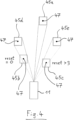
- the sanity check includes an occlusion check as exemplarily shown in Fig. 4 .
- the upper (farthest) expectation area 45a, the lower (nearest) left expectation area 45b and the lower (nearest) right expectation area 45c are not occluded by any other expectation area 45.
- the two intermediate expectation areas 45d, 45e are occluded by the lower expectation areas 45b, 45c, respectively.
- the occlusion check includes a step of determining if an object detection 47 to be removed is occluded by a newly occurred object detection 47. In case of an occlusion, it is further checked, by means of the reset counter of the corresponding expectation area 45, if the occluding object detection 47 is likely to be a ghost detection itself.
- the object detection 47 is removed despite the occlusion. If the reset counter is low, for example 0, the occluded object detection 47 is kept. Thus, in the situation according to Fig. 4 , the upper central expectation area 45a and the right intermediate expectation area 45e are removed, while the left intermediate expectation area 45b is kept.
- an exemplary occupancy map 19 is shown before a removal of object detections 47 as described above.
- the occupancy map 19 is shown after a removal of object detections 47 as described above. It can be understood that the occupancy map 19 shown in the right panel of Fig. 5 has been cleaned from traces 25, ghost targets and the like.
- a trace map 49 including only the removed object detections 47 is shown.
- the positional coordinates x, y indicated in Fig. 5 refer to a lateral (x) and a longitudinal (y) distance from a predefined reference point in m.
- Fig. 6 shows an occupancy map determination system 600 according to various embodiments.
- the occupancy map determination system 600 may include a sensor data acquiring circuit 602, an object detections determination circuit 604, an overlay circuit 606, a definition circuit 608, an adjustment circuit 610, and a removing circuit 612.
- the occupancy map determination system 600 may be a system for determining an occupancy map of a vicinity of a vehicle.
- the sensor data acquiring circuit 602 may be configured to successively acquire sensor data of a sensor system arranged at the vehicle.
- the object detections determination circuit 604 may be configured to determine object detections based on the acquired sensor data.
- the overlay circuit 606 may be configured to overlay the determined object detections in a spatial representation of the vicinity of the vehicle to determine the occupancy map.
- the definition circuit 608 may be configured to define, for at least one object detection of a first data acquisition process, an expectation area extending around the object detection.
- the adjustment circuit 610 may be configured to adjust, if an object detection of a subsequent second data acquisition process is present within the expectation area and a predefined stop criterion is not fulfilled, the position of the expectation area based on a difference between the position of the object detection of the first data acquisition process and the position of the object detection of the second data acquisition process.
- the removing circuit 612 may be configured to remove at least one object detection of the expectation area from the occupancy map if no object detection can be determined in the expectation area for a predetermined number of successive data acquisition.
- the sensor data acquiring circuit 602, the object detections determination circuit 604, the overlay circuit 606, the definition circuit 608, the adjustment circuit 610, and the removing circuit 612 may be coupled with each other, e.g. via an electrical connection 614, such as e.g. a cable or a computer bus or via any other suitable electrical connection to exchange electrical signals.
- an electrical connection 614 such as e.g. a cable or a computer bus or via any other suitable electrical connection to exchange electrical signals.
- a “circuit” may be understood as any kind of a logic implementing entity, which may be special purpose circuitry or a processor executing a program stored in a memory, firmware, or any combination thereof.
- Fig. 7 shows a computer system 700 with a plurality of computer hardware components configured to carry out steps of a computer implemented method for determining an occupancy map of a vicinity of a vehicle according to various embodiments.
- the computer system 700 may include a processor 702, a memory 704, and a non-transitory data storage 706.
- a sensor system 708 may be provided as part of the computer system 700 (like illustrated in Fig. 7 ), or may be provided external to the computer system 700.
- the processor 702 may carry out instructions provided in the memory 704.
- the non-transitory data storage 706 may store a computer program, including the instructions that may be transferred to the memory 704 and then executed by the processor 702.
- the sensor system 708 may be used to acquire sensor data as described above.
- the processor 702, the memory 704, and the non-transitory data storage 706 may be coupled with each other, e.g. via an electrical connection 710, such as e.g. a cable or a computer bus or via any other suitable electrical connection to exchange electrical signals.
- the sensor system 708 may be coupled to the computer system 700, for example via an external interface, or may be provided as parts of the computer system (in other words: internal to the computer system, for example coupled via the electrical connection 710).
- Coupled or “connection” are intended to include a direct “coupling” (for example via a physical link) or direct “connection” as well as an indirect “coupling” or indirect “connection” (for example via a logical link), respectively.
Landscapes
- Engineering & Computer Science (AREA)
- General Physics & Mathematics (AREA)
- Physics & Mathematics (AREA)
- Theoretical Computer Science (AREA)
- Remote Sensing (AREA)
- Radar, Positioning & Navigation (AREA)
- Data Mining & Analysis (AREA)
- Multimedia (AREA)
- Automation & Control Theory (AREA)
- Life Sciences & Earth Sciences (AREA)
- Artificial Intelligence (AREA)
- Bioinformatics & Cheminformatics (AREA)
- Bioinformatics & Computational Biology (AREA)
- Computer Vision & Pattern Recognition (AREA)
- Evolutionary Biology (AREA)
- Evolutionary Computation (AREA)
- General Engineering & Computer Science (AREA)
- Quality & Reliability (AREA)
- Traffic Control Systems (AREA)
Abstract
Description
- The present disclosure relates to vehicles, systems and methods for determining an occupancy map in the vicinity of a vehicle.
- An occupancy map, also referred to as occupancy grid or occupancy map grid, is a map of cells containing information of the cell being occupied by some kind of object. The cells may have a fixed width, length and height. Occupancy maps are widely used in Advanced Driver Assistance Systems (ADAS) and autonomous driving applications, because an occupancy map can be interpreted as a map of obstacles around the vehicle. Each occupied cell may represent a non drivable area. An inverted occupancy map can be interpreted as a free space map showing the drivable regions.
- Usually, only stationary objects are listed in an occupancy map. Moving objects like other vehicles should not form entries of an occupancy map. In practice, however, a reliable classification of object detections as "moving" or "stationary" is difficult. In particular, slow moving targets like pedestrians or temporarily stationary objects like vehicles stopping at traffic lights can be falsely identified as obstacles, for example due to inaccuracies in measurement (for example Doppler error) and computation. Such falsely identified obstacles result in ghost targets or traces in the occupancy map and impair the representation of the drivable space.
- Accordingly, there is a need for efficient and reliable methods and systems for determining an occupancy map.
- The present disclosure provides a computer implemented method, a computer system and a non-transitory computer readable medium according to the independent claims. Embodiments are given in the dependent claims, the description and the drawings.
- In one aspect, the present disclosure is directed at a computer implemented method for determining an occupancy map of a vicinity of a vehicle, the method comprising the following steps carried out by computer hardware components:
- (i) successively acquiring sensor data of a sensor system arranged at the vehicle,
- (ii) determining object detections based on the acquired sensor data,
- (iii) overlaying the determined object detections in a spatial representation of the vicinity of the vehicle to determine the occupancy map,
- (iv) defining, for at least one object detection of a first data acquisition process, an expectation area extending around the object detection,
- (v) adjusting, if an object detection of a subsequent second data acquisition process is present within the expectation area and a predefined stop criterion is not fulfilled, the position of the expectation area based on a difference between the position of the object detection of the first data acquisition process and the position of the object detection of the second data acquisition process, and
- (vi) removing at least one object detection of the expectation area from the occupancy map if no object detection can be determined in the expectation area for a predetermined number of successive data acquisition processes.
- In other words, if in the first acquired sensor data a potential object or part of an object is detected, i. e. if it is determined that an object is potentially present or present with a predefined probability, then an expectation area extending around the respective object is created. In the course of further data acquisition processes, the expectation area is repositioned to follow the potentially present object. If the object disappears in later sensor data, the corresponding entry in the occupancy map is removed, because it is assumed that the object has moved out of the expectation area. The repositioning of the expectation area ensures that the focus is kept on the potential object.
- It has been found that a repositioning and selective resetting of expectation areas as described herein provides a cleaned up occupancy map which is at least essentially free from undesired ghost targets and traces. The application of a stop criterion avoids problems arising from continuously moving expectation areas, for example due to a slowly moving pedestrian.
- The sensor system may comprise a radar sensor and/or a lidar sensor. The first and the second data acquisition process may correspond to successive scans or frames of the radar and/or lidar sensor. In the context of the present disclosure, an object detection corresponds to a detected surface spot of an object present in the vicinity of the vehicle.
- The position of the expectation area may be adjusted in step (v) such that, after the adjustment, a centre of the expectation area is close to all accumulated occupancy probabilities. The adjustment could be alternatively such that the object detection of the subsequent second data acquisition process is centrally positioned in the adjusted expectation area. If the difference between the position of the object detection of the first data acquisition process and the position of the object detection of the second data acquisition process is zero, no adjustment is necessary.
- In step (vi), any object detections or entries located in the expectation area may be removed from the occupancy map. Further, the step (iv) may be carried out for each object detection of the first data acquisition process.
- The method may further include one or more of the following features:
The object detections may be respectively determined based on an occupancy probability which is updated after each data acquisition process. The occupancy probability may be defined as a log odds ratio. Determining object detections in step (ii) may comprise determining peaks of the log odds ratio. It may be determined that no object detection can be determined within the expectation area if no occupancy probability in the expectation area exceeds a predefined detection threshold. The stop criterion may be defined based on a cumulative occupancy probability of the expectation area. The stop criterion may be fulfilled if the cumulative occupancy probability of the expectation area exceeds a predefined trace threshold. Removing the at least one object detection of the expectation area in step (vi) may comprise setting the occupancy probabilities of the expectation area to zero. The object detections determined in step (ii) may be classified as either moving or stationary. Only object detections classified as stationary may be overlaid in the spatial representation of the vicinity of the vehicle in step (iii). The at least one object detection which has been removed from the occupancy map in step (vi) may be stored in a trace map separate from the occupancy map. A sanity check may be performed if no object detection can be determined in the expectation area for a predetermined number of successive data acquisition processes after the first data acquisition process and the object detection may be only removed from the occupancy map if the result of the sanity check is positive. The sanity check may comprise an occlusion check and the result of the sanity check may be negative if the expectation area is occluded by another object detection or another expectation area. - According to an embodiment, the object detections are respectively determined based on an occupancy probability which is updated after each data acquisition process. The occupancy map may comprise a plurality of cells, wherein an occupancy probability is assigned to each of the cells.
- It will be understood that the occupancy map may be represented by a matrix (for a two-dimensional occupancy map) or a tensor (for a three-dimensional occupancy map), wherein each of the two dimensions of the matrix (or each of the three dimensions of the tensor) corresponds to a dimension in space. An entry of a cell of the matrix or the tensor at a specific position may correspond to information whether or not an object is potentially present at that location and may be presented by a Boolean value such as "true" for "object present" and "false" for "object not present". Alternatively, the probability may be indicated by a number between 0 and 1 or between 0% and 100%.
- According to another aspect, the occupancy probability is defined as a log odds ratio, i. e. as the logarithm, for example the natural logarithm, of the ratio between the probability of the cell being occupied to the probability of the cell not being occupied. Compared to a raw probability value, the log odds ratio can be easily updated with new data.
- According to another aspect, determining object detections in step (ii) comprises determining peaks of the log odds ratio. In other words, an object detection may be assumed to be present whenever a log odds peak value occurs in an update cycle. A peak value of the updated log odds ratio corresponds to an intensity peak of the current sensor output.
- According to another aspect, no object detection can be determined in the expectation area if no occupancy probability in the expectation area exceeds a predefined detection threshold, i. e. if all occupancy probabilities of the cells of the expectation area respectively don't exceed the predefined detection threshold. The detection threshold may be 0.5. A reset counter may be incremented when no object detection can be determined in the expectation area, i. e. when no log odds ratio update is found.
- According to another aspect, the step (vi) includes checking, for each data acquisition process, if a log odds ratio of the expectation area exceeds a predefined detection threshold. For example, once the expectation area has been defined, it may be checked for each subsequent data acquisition process, if the following expectation criterion is fulfilled:

- According to another aspect, the stop criterion is defined based on a cumulative occupancy probability of the expectation area. The cumulative occupancy probability of the expectation area may be the sum of probabilities of all cells of the expectation area. I. e. if an expectation area is overfilled with high probability entries due to traces of a moving target, the repositioning is stopped. It has turned out that such a stop criterion enables a reliable removal of slow moving targets such as pedestrians from the occupancy map.
- According to another aspect, the stop criterion is fulfilled if the cumulative occupancy probability of the expectation area exceeds a predefined threshold.
- It may be checked if the stop criterion is fulfilled by summing up all object detections that are inside the expectation area and checking if the determined sum exceeds a predefined threshold. For example, it may be checked if the following stop criterion is fulfilled:

- According to another aspect, removing the at least one object detection of the expectation area in step (vi) comprises setting the occupancy probabilities of the expectation area, i. e. of all cells of the expectation area, to zero. Thus, undesired ghost entries, traces and the like are deleted.
- According to another aspect, the object detections determined in step (ii) are classified as either moving or stationary and only object detections classified as stationary are overlaid in the spatial representation of the vicinity of the vehicle in step (iii). Due to inaccuracies of the classifier, such object detections may in fact correspond to moving objects, in particular to slowly moving objects or to temporarily moving objects. Such entries of the occupancy map may be subsequently removed from the occupancy map by a method as described herein.
- According to another aspect, the at least one object detection which has been removed from the occupancy map in step (vi) is stored in a trace map separate from the occupancy map. Such a trace map may be used, for example, for a selective tracking of slowly moving pedestrians by means of a tracker and/or for a training of a machine learning algorithm able to identify pedestrians.
- According to another aspect, a sanity check is performed if no object detection can be determined in the expectation area for a predetermined number of successive data acquisition processes after the first data acquisition process and the object detection is only removed from the occupancy map if the result of the sanity check is positive. Due to the complexity of the environment, there is a certain risk that no updated object detection is found in an expectation area despite an actual presence of an object. The sanity check avoids false removals of entries from the occupancy map.
- According to another aspect, the sanity check comprises an occlusion check and the result of the sanity check is negative if the expectation area is occluded by another object detection or another expectation area. If an area is located behind a newly detected object from the perspective of the corresponding sensor, objects actually present in that area can't be detected due to occlusion. The sanity check provides for a keeping of information related to the occluded area.
- According to another aspect, in step (i) the distance of the object detection to a previously defined expectation area is determined and a further expectation area is only defined if the determined distance exceeds a predefined distance threshold. It has been found that such a measure can control an area overlap to be minimal in order to not create unnecessary expectation areas.
- In another aspect, the present disclosure is directed at a computer system, said computer system being configured to carry out several or all steps of the computer implemented method described herein.
- The computer system may comprise a processing unit, at least one memory unit and at least one non-transitory data storage. The non-transitory data storage and/or the memory unit may comprise a computer program for instructing the computer to perform several or all steps or aspects of the computer implemented method described herein.
- In another aspect, the present disclosure is directed at a vehicle comprising a computer system as described herein and the sensor system. The sensor system may comprise several short range radar sensors and at least one medium range radar sensor.
- In another aspect, the present disclosure is directed at a non-transitory computer readable medium comprising instructions for carrying out several or all steps or aspects of the computer implemented method described herein. The computer readable medium may be configured as: an optical medium, such as a compact disc (CD) or a digital versatile disk (DVD); a magnetic medium, such as a hard disk drive (HDD); a solid state drive (SSD); a read only memory (ROM), such as a flash memory; or the like. Furthermore, the computer readable medium may be configured as a data storage that is accessible via a data connection, such as an internet connection. The computer readable medium may, for example, be an online data repository or a cloud storage.
- The present disclosure is also directed at a computer program for instructing a computer to perform several or all steps or aspects of the computer implemented method described herein.
- Exemplary embodiments and functions of the present disclosure are described herein in conjunction with the following drawings, showing schematically:
- Fig. 1
- a vicinity of a host vehicle in a schematic top view;
- Fig. 2
- a flow diagram illustrating steps of a method for determining an occupancy map in the vicinity of the host vehicle according to various embodiments;
- Fig. 3
- a region of interest of the vicinity of the host vehicle according to
Fig. 1 including expectation areas extending around object detections; - Fig. 4
- an illustration of an occlusion of expectation areas by other expectation areas;
- Fig. 5
- a comparison of occupancy maps before and after a removal of traces according to various embodiments as well as a trace map;
- Fig. 6
- an occupancy map determination system according to various embodiments; and
- Fig. 7
- a computer system with a plurality of computer hardware components configured to carry out steps of a computer implemented method for determining an occupancy map according to various embodiments.
-
Fig. 1 depicts, in a top view, a motor vehicle orhost vehicle 11 including acomputer system 12 and a sensor system 13 connected to thecomputer system 12. The sensor system 13 includes a plurality ofsensors 15 configured to scan the vicinity of thehost vehicle 11 for objects such asother vehicles 16,pedestrians 17 or stationary objects like traffic lights 18. Thesensors 15 of the sensor system 13 may be radar (radio detection and ranging) sensors, lidar (light detection and ranging) sensors and/or time-of-flight cameras. Thecomputer system 12 receives data from thesensors 15 and provides an "advanced driver assistance" functionality or an autonomous driving functionality based on an evaluation of the received data. - According to various embodiments, an
occupancy map 19 of the vicinity of thehost vehicle 11 may be determined by accumulating readings from thesensors 15 of the sensor system 13 and transforming the accumulated sensor readings to probabilities over time. Theoccupancy map 19 may include a two-dimensional or three-dimensional grid of cells (not shown), wherein an occupancy probability is assigned to each of the cells, as is known in the art. The occupancy probability may be updated after each data acquisition process, i. e. after each frame or scan of thesensors 15. The occupancy probability may be indicated as a log odds ratio. - The
occupancy map 19 shows obstacles in form of stationary objects and thus also shows the drivable space, i. e. the space which is free from obstacles. Generally, only stationary objects should be indicated in theoccupancy map 19. Therefore, the detected objects may be classified as either moving objects or stationary objects. Entries of theoccupancy map 19, i. e. cells identified as "probably occupied", are created for stationary objects, but not for moving objects. According to various embodiments, a classifier based on an artificial neural network or on a Support Vector Machine may be used for the classification. Azimuth based Doppler calculations may be used for stationary/moving classification. - It is possible that a slowly moving target like a
pedestrian 17 is not properly identified as a moving object due to inaccuracies in measurement and/or computation, which may result, as schematically shown inFig. 1 , in atrace 25 present in theoccupancy map 19. Also, avehicle 16 stopping at traffic lights 18 may be classified as a stationary object, despite a later movement. The space previously occupied by thisvehicle 16 continues to exist in theoccupancy map 19 as atrace 25. Obviously,such traces 25 are undesired because they lead to a confusion of control modules which use the information relating to the drivable space included in theoccupancy map 19 as an input. - Therefore, according to various embodiments, the
computer system 12 is configured to clean theoccupancy map 19 fromtraces 25 as described below with reference toFig. 2 showing a flow diagram andFig. 3 showing a region ofinterest 40 located in front of thehost vehicle 11 with respect to a normal or designated driving direction 41 andexpectation areas 45 extending aroundobject detections 47 within the region ofinterest 40. - In a
first step 31, the region ofinterest 40 and theexpectation areas 45 are created. For eachobject detection 47 determined in a current scan of the sensors 15 (Fig. 1 ), anindividual expectation area 45 having a fixed size (in pixels or cells), for example 10x10 pixels, is created. Each of the object detections 47 is located centrally within the correspondingexpectation area 45. - An
object detection 47 corresponds to a peak of the log odds ratio. Specifically, anexpectation area 45 is created when a peak of the log odds ratio occurs in a specific scan and the peak doesn't belong to an already existingexpectation area 45. Theexpectation area 45 may be positioned such that the peak of the updated log odds ratio is located in the center of theexpectation area 45. - The distance of an
object detection 47 to a previously definedexpectation area 45 may be determined. Thefurther expectation area 45 may only be created if the determined distance exceeds a predefined distance threshold in order to prevent the creation ofunnecessary expectation areas 45. - In a
step 32, theexpectation areas 45 are updated based on data of a consecutive scan. If anobject detection 47 belonging to an existingexpectation area 45 is found in the consecutive scan, the position of theexpectation area 45 is adjusted such that the center of the adjusted expectation area 45' is close to the accumulated occupancy probabilities. - An
object detection 47 belonging to an existingexpectation area 45 is found if at least one expectation criterion is fulfilled. The expectation criterion may be fulfilled if the log odds ratio for each cell of theexpectation area 45 is greater than a predefined detection threshold, for example 0.5. If the expectation criterion is not fulfilled, a reset counter is incremented for thecorresponding expectation area 45. - The repositioning of the
expectation area 45 is stopped if a predefined stop criterion is fulfilled. The stop criterion may be defined based on a cumulative occupancy probability of theexpectation area 45. For example, the stop criterion may be fulfilled if the sum of the occupancy probabilities of all cells of therespective expectation area 45 exceeds a predefined trace threshold. - If the expectation criterion for a
specific expectation area 45 is not fulfilled for a predefined number of scans, for example 6 scans, a sanity check including an occlusion check is performed. Based on the sanity check, the entries of the occupancy map located in theexpectation area 45 are kept or removed. Specifically, if the sanity check is negative, the entries belonging to theexpectation area 45 are kept. If the sanity check is positive, it is assumed that the entries belonging to theexpectation area 45 are traces 25 (Fig. 1 ) and, in astep 33, any entries belonging to therespective expectation area 45 are removed. In other words, the occupancy probabilities of the cells of theexpectation area 45 are set to zero. The removed entries may be stored in a computer storage medium. - The sanity check includes an occlusion check as exemplarily shown in
Fig. 4 . The upper (farthest)expectation area 45a, the lower (nearest) left expectation area 45b and the lower (nearest)right expectation area 45c are not occluded by anyother expectation area 45. In contrast, the twointermediate expectation areas lower expectation areas 45b, 45c, respectively. The occlusion check includes a step of determining if anobject detection 47 to be removed is occluded by a newly occurredobject detection 47. In case of an occlusion, it is further checked, by means of the reset counter of thecorresponding expectation area 45, if the occludingobject detection 47 is likely to be a ghost detection itself. If this is the case, for example as the reset counter of thecorresponding expectation area 45c exceeds 3, theobject detection 47 is removed despite the occlusion. If the reset counter is low, for example 0, theoccluded object detection 47 is kept. Thus, in the situation according toFig. 4 , the uppercentral expectation area 45a and the rightintermediate expectation area 45e are removed, while the left intermediate expectation area 45b is kept. - In the left panel of
Fig. 5 , anexemplary occupancy map 19 is shown before a removal ofobject detections 47 as described above. In the right panel ofFig. 5 , theoccupancy map 19 is shown after a removal ofobject detections 47 as described above. It can be understood that theoccupancy map 19 shown in the right panel ofFig. 5 has been cleaned fromtraces 25, ghost targets and the like. In the central panel ofFig. 5 , atrace map 49 including only the removedobject detections 47 is shown. The positional coordinates x, y indicated inFig. 5 refer to a lateral (x) and a longitudinal (y) distance from a predefined reference point in m. - The embodiments described herein enable a fast, simple and instantaneous trace detection in an
occupancy map 19. The computational effort is only little. Traces, multi-paths, ghost targets and the like are effectively deleted. -
Fig. 6 shows an occupancymap determination system 600 according to various embodiments. The occupancymap determination system 600 may include a sensordata acquiring circuit 602, an objectdetections determination circuit 604, anoverlay circuit 606, adefinition circuit 608, anadjustment circuit 610, and a removingcircuit 612. The occupancymap determination system 600 may be a system for determining an occupancy map of a vicinity of a vehicle. - The sensor
data acquiring circuit 602 may be configured to successively acquire sensor data of a sensor system arranged at the vehicle. - The object detections
determination circuit 604 may be configured to determine object detections based on the acquired sensor data. - The
overlay circuit 606 may be configured to overlay the determined object detections in a spatial representation of the vicinity of the vehicle to determine the occupancy map. - The
definition circuit 608 may be configured to define, for at least one object detection of a first data acquisition process, an expectation area extending around the object detection. - The
adjustment circuit 610 may be configured to adjust, if an object detection of a subsequent second data acquisition process is present within the expectation area and a predefined stop criterion is not fulfilled, the position of the expectation area based on a difference between the position of the object detection of the first data acquisition process and the position of the object detection of the second data acquisition process. - The removing
circuit 612 may be configured to remove at least one object detection of the expectation area from the occupancy map if no object detection can be determined in the expectation area for a predetermined number of successive data acquisition. - The sensor
data acquiring circuit 602, the objectdetections determination circuit 604, theoverlay circuit 606, thedefinition circuit 608, theadjustment circuit 610, and the removingcircuit 612 may be coupled with each other, e.g. via anelectrical connection 614, such as e.g. a cable or a computer bus or via any other suitable electrical connection to exchange electrical signals. - A "circuit" may be understood as any kind of a logic implementing entity, which may be special purpose circuitry or a processor executing a program stored in a memory, firmware, or any combination thereof.
-
Fig. 7 shows acomputer system 700 with a plurality of computer hardware components configured to carry out steps of a computer implemented method for determining an occupancy map of a vicinity of a vehicle according to various embodiments. Thecomputer system 700 may include aprocessor 702, amemory 704, and anon-transitory data storage 706. Asensor system 708 may be provided as part of the computer system 700 (like illustrated inFig. 7 ), or may be provided external to thecomputer system 700. - The
processor 702 may carry out instructions provided in thememory 704. Thenon-transitory data storage 706 may store a computer program, including the instructions that may be transferred to thememory 704 and then executed by theprocessor 702. Thesensor system 708 may be used to acquire sensor data as described above. - The
processor 702, thememory 704, and thenon-transitory data storage 706 may be coupled with each other, e.g. via anelectrical connection 710, such as e.g. a cable or a computer bus or via any other suitable electrical connection to exchange electrical signals. Thesensor system 708 may be coupled to thecomputer system 700, for example via an external interface, or may be provided as parts of the computer system (in other words: internal to the computer system, for example coupled via the electrical connection 710). - The terms "coupling" or "connection" are intended to include a direct "coupling" (for example via a physical link) or direct "connection" as well as an indirect "coupling" or indirect "connection" (for example via a logical link), respectively.
- It will be understood that what has been described for one of the methods above may analogously hold true for the
occupancy map determination 600 and/or for thecomputer system 700. -
- 11
- host vehicle
- 12
- computer system
- 13
- sensor system
- 15
- sensor
- 16
- other vehicle
- 17
- pedestrian
- 18
- traffic lights
- 19
- occupancy map
- 25
- trace
- 31-33
- steps
- 40
- region of interest
- 41
- normal driving direction
- 45, 45', 45a-e
- expectation area
- 47, 47'
- object detection
- 49
- trace map
- 600
- occupancy map determination system
- 602
- sensor data acquiring circuit
- 604
- object detections determination circuit
- 606
- overlay circuit
- 608
- definition circuit
- 610
- adjustment circuit
- 612
- removing circuit
- 614
- connection
- 700
- computer system
- 702
- processor
- 704
- memory
- 706
- non-transitory data storage
- 708
- sensor system
- 710
- connection
Claims (15)
- Computer implemented method for determining an occupancy map (19) of a vicinity of a vehicle (11),
the method comprising the following steps carried out by computer hardware components:(i) successively acquiring sensor data of a sensor system (13) arranged at the vehicle (11),(ii) determining object detections (47) based on the acquired sensor data,(iii) overlaying the determined object detections (47) in a spatial representation of the vicinity of the vehicle to determine the occupancy map (19),(iv) defining, for at least one object detection (47) of a first data acquisition process, an expectation area (45) extending around the object detection (47),(v) adjusting, if an object detection (47') of a subsequent second data acquisition process is present within the expectation area (45) and a predefined stop criterion is not fulfilled, the position of the expectation area (45) based on a difference between the position of the object detection (47) of the first data acquisition process and the position of the object detection (47') of the second data acquisition process; and(vi) removing at least one object detection (47) of the expectation area (45) from the occupancy map (19) if no object detection (47) can be determined in the expectation area (45) for a predetermined number of successive data acquisition processes. - The computer implemented method of claim 1,
wherein the object detections (47) are respectively determined based on an occupancy probability which is updated after each data acquisition process. - The computer implemented method of claim 2,
wherein the occupancy probability is defined as a log odds ratio,
in particular wherein determining object detections (47) in step (ii) comprises determining peaks of the log odds ratio. - The computer implemented method of at least one of claims 2 and 3,
wherein in step (vi) no object detection (47) can be determined in the expectation area (45) if no occupancy probability in the expectation area (45) exceeds a predefined detection threshold. - The computer implemented method of at least one of claims 3 and 4,
wherein step (vi) includes checking, for each data acquisition process, if a log odds ratio of the expectation area (45) exceeds a predefined detection threshold. - The computer implemented method of at least one of claims 2 to 5,
wherein the stop criterion is defined based on a cumulative occupancy probability of the expectation area (45). - The computer implemented method of claim 6,
wherein the stop criterion is fulfilled if the cumulative occupancy probability of the expectation area (45) exceeds a predefined threshold. - The computer implemented method of at least one of claims 1 to 7,
wherein it is checked if the stop criterion is fulfilled by summing up all object detections (47) that are inside the expectation area (45) and checking if the determined sum exceeds a predefined threshold. - The computer implemented method of at least one of claims 2 to 8,
wherein removing the at least one object detection (47) of the expectation area (45) in step (vi) comprises setting the occupancy probabilities of the expectation area (45) to zero. - The computer implemented method of at least one of claims 1 to 9,
wherein the object detections (47) determined in step (ii) are classified as either moving or stationary and only object detections (47) classified as stationary are overlaid in the spatial representation of the vicinity of the vehicle (11) in step (iii). - The computer implemented method of at least one of claims 1 to 10,
wherein the at least one object detection (47) which has been removed from the occupancy map (19) in step (vi) is stored in a trace map (49) separate from the occupancy map (19). - The computer implemented method of at least one of claims 1 to 11,
wherein a sanity check is performed if no object detection (47) can be determined in the expectation area (45) for a predetermined number of successive data acquisition processes after the first data acquisition process and the object detection (47) is only removed from the occupancy map (19) if the result of the sanity check is positive,
wherein the sanity check comprises an occlusion check and the result of the sanity check is negative if the expectation area (45) is occluded by another object detection (47) or another expectation area (45). - Computer system (12), the computer system comprising a plurality of computer hardware components configured to carry out steps of the computer implemented method of at least one of claims 1 to 12.
- Vehicle (11) comprising
the computer system (12) of claim 13 and
a sensor system (13). - Non-transitory computer readable medium comprising instructions for carrying out the computer implemented method of at least one of claims 1 to 12.
Priority Applications (2)
| Application Number | Priority Date | Filing Date | Title |
|---|---|---|---|
| US17/460,895 US20220067395A1 (en) | 2020-08-31 | 2021-08-30 | Vehicles, Systems and Methods for Determining an Occupancy Map of a Vicinity of a Vehicle |
| CN202111012746.0A CN114114269A (en) | 2020-08-31 | 2021-08-31 | Vehicle, system and method for determining occupancy map in proximity to vehicle |
Applications Claiming Priority (1)
| Application Number | Priority Date | Filing Date | Title |
|---|---|---|---|
| EP20193680.4A EP3961481A1 (en) | 2020-08-31 | 2020-08-31 | Vehicles, systems and methods for determining an occupancy map of a vicinity of a vehicle |
Publications (1)
| Publication Number | Publication Date |
|---|---|
| EP4145407A1 true EP4145407A1 (en) | 2023-03-08 |
Family
ID=72292415
Family Applications (2)
| Application Number | Title | Priority Date | Filing Date |
|---|---|---|---|
| EP20193680.4A Withdrawn EP3961481A1 (en) | 2020-08-31 | 2020-08-31 | Vehicles, systems and methods for determining an occupancy map of a vicinity of a vehicle |
| EP21190812.4A Pending EP4145407A1 (en) | 2020-08-31 | 2021-08-11 | Vehicles, systems and methods for determining an occupancy map of a vicinity of a vehicle |
Family Applications Before (1)
| Application Number | Title | Priority Date | Filing Date |
|---|---|---|---|
| EP20193680.4A Withdrawn EP3961481A1 (en) | 2020-08-31 | 2020-08-31 | Vehicles, systems and methods for determining an occupancy map of a vicinity of a vehicle |
Country Status (1)
| Country | Link |
|---|---|
| EP (2) | EP3961481A1 (en) |
Citations (2)
| Publication number | Priority date | Publication date | Assignee | Title |
|---|---|---|---|---|
| US20190384302A1 (en) * | 2018-06-18 | 2019-12-19 | Zoox, Inc. | Occulsion aware planning and control |
| US20200103523A1 (en) * | 2018-09-28 | 2020-04-02 | Zoox, Inc. | Radar Spatial Estimation |
-
2020
- 2020-08-31 EP EP20193680.4A patent/EP3961481A1/en not_active Withdrawn
-
2021
- 2021-08-11 EP EP21190812.4A patent/EP4145407A1/en active Pending
Patent Citations (2)
| Publication number | Priority date | Publication date | Assignee | Title |
|---|---|---|---|---|
| US20190384302A1 (en) * | 2018-06-18 | 2019-12-19 | Zoox, Inc. | Occulsion aware planning and control |
| US20200103523A1 (en) * | 2018-09-28 | 2020-04-02 | Zoox, Inc. | Radar Spatial Estimation |
Non-Patent Citations (2)
| Title |
|---|
| MOHAMED ESSAYED BOUZOURAA ET AL: "Fusion of occupancy grid mapping and model based object tracking for driver assistance systems using laser and radar sensors", 2013 IEEE INTELLIGENT VEHICLES SYMPOSIUM (IV), 1 June 2010 (2010-06-01), pages 294 - 300, XP055554922, ISSN: 1931-0587, DOI: 10.1109/IVS.2010.5548106 * |
| RADU DANESCU ET AL: "Modeling and Tracking the Driving Environment With a Particle-Based Occupancy Grid", IEEE TRANSACTIONS ON INTELLIGENT TRANSPORTATION SYSTEMS, IEEE, PISCATAWAY, NJ, USA, vol. 12, no. 4, 1 December 2011 (2011-12-01), pages 1331 - 1342, XP011379328, ISSN: 1524-9050, DOI: 10.1109/TITS.2011.2158097 * |
Also Published As
| Publication number | Publication date |
|---|---|
| EP3961481A1 (en) | 2022-03-02 |
Similar Documents
| Publication | Publication Date | Title |
|---|---|---|
| CN112417967B (en) | Obstacle detection method, obstacle detection device, computer device, and storage medium | |
| Negru et al. | Image based fog detection and visibility estimation for driving assistance systems | |
| CN111932901B (en) | Road vehicle tracking detection apparatus, method and storage medium | |
| EP3403216A1 (en) | Systems and methods for augmenting upright object detection | |
| CN109766867B (en) | Vehicle running state determination method and device, computer equipment and storage medium | |
| US11436839B2 (en) | Systems and methods of detecting moving obstacles | |
| Dey et al. | VESPA: A framework for optimizing heterogeneous sensor placement and orientation for autonomous vehicles | |
| CN113435237B (en) | Object state recognition device, recognition method, and computer-readable recording medium, and control device | |
| Berriel et al. | A particle filter-based lane marker tracking approach using a cubic spline model | |
| CN112633182A (en) | Vehicle state detection method, device, equipment and storage medium | |
| CN110426714B (en) | Obstacle identification method | |
| US20220171975A1 (en) | Method for Determining a Semantic Free Space | |
| CN112348845B (en) | System and method for parking space detection and tracking | |
| EP4145407A1 (en) | Vehicles, systems and methods for determining an occupancy map of a vicinity of a vehicle | |
| US20220067395A1 (en) | Vehicles, Systems and Methods for Determining an Occupancy Map of a Vicinity of a Vehicle | |
| EP4145398A1 (en) | Systems and methods for vehicle camera obstruction detection | |
| CN116358528A (en) | Map updating method, map updating device, self-mobile device and storage medium | |
| CN115761668A (en) | Camera stain recognition method and device, vehicle and storage medium | |
| CN117523914A (en) | Collision early warning method, device, equipment, readable storage medium and program product | |
| CN112356845B (en) | Method, device and equipment for predicting motion state of target and vehicle | |
| CN117644815B (en) | Blind zone alarming method, device, equipment and system based on intelligent car lamp system | |
| JP7384181B2 (en) | Image collection device, image collection method, and computer program for image collection | |
| CN112906424B (en) | Image recognition method, device and equipment | |
| US11636690B2 (en) | Environment perception device and method of mobile vehicle | |
| KR101927634B1 (en) | Apparatus and method for removing environmental factor |
Legal Events
| Date | Code | Title | Description |
|---|---|---|---|
| PUAI | Public reference made under article 153(3) epc to a published international application that has entered the european phase |
Free format text: ORIGINAL CODE: 0009012 |
|
| STAA | Information on the status of an ep patent application or granted ep patent |
Free format text: STATUS: THE APPLICATION HAS BEEN PUBLISHED |
|
| PUAB | Information related to the publication of an a document modified or deleted |
Free format text: ORIGINAL CODE: 0009199EPPU |
|
| PUAI | Public reference made under article 153(3) epc to a published international application that has entered the european phase |
Free format text: ORIGINAL CODE: 0009012 |
|
| AK | Designated contracting states |
Kind code of ref document: A1 Designated state(s): AL AT BE BG CH CY CZ DE DK EE ES FI FR GB GR HR HU IE IS IT LI LT LU LV MC MK MT NL NO PL PT RO RS SE SI SK SM TR |
|
| RAP3 | Party data changed (applicant data changed or rights of an application transferred) |
Owner name: APTIV TECHNOLOGIES LIMITED |
|
| STAA | Information on the status of an ep patent application or granted ep patent |
Free format text: STATUS: REQUEST FOR EXAMINATION WAS MADE |
|
| 17P | Request for examination filed |
Effective date: 20230711 |
|
| RBV | Designated contracting states (corrected) |
Designated state(s): AL AT BE BG CH CY CZ DE DK EE ES FI FR GB GR HR HU IE IS IT LI LT LU LV MC MK MT NL NO PL PT RO RS SE SI SK SM TR |