EP4145384A1 - Bildentrauschungsverfahren und -vorrichtung, elektronische vorrichtung und speichermedium - Google Patents
Bildentrauschungsverfahren und -vorrichtung, elektronische vorrichtung und speichermedium Download PDFInfo
- Publication number
- EP4145384A1 EP4145384A1 EP21795374.4A EP21795374A EP4145384A1 EP 4145384 A1 EP4145384 A1 EP 4145384A1 EP 21795374 A EP21795374 A EP 21795374A EP 4145384 A1 EP4145384 A1 EP 4145384A1
- Authority
- EP
- European Patent Office
- Prior art keywords
- image
- training
- network
- convolutional layer
- initial
- Prior art date
- Legal status (The legal status is an assumption and is not a legal conclusion. Google has not performed a legal analysis and makes no representation as to the accuracy of the status listed.)
- Granted
Links
Images


Classifications
-
- G—PHYSICS
- G06—COMPUTING OR CALCULATING; COUNTING
- G06T—IMAGE DATA PROCESSING OR GENERATION, IN GENERAL
- G06T5/00—Image enhancement or restoration
- G06T5/70—Denoising; Smoothing
-
- G—PHYSICS
- G06—COMPUTING OR CALCULATING; COUNTING
- G06N—COMPUTING ARRANGEMENTS BASED ON SPECIFIC COMPUTATIONAL MODELS
- G06N3/00—Computing arrangements based on biological models
- G06N3/02—Neural networks
- G06N3/04—Architecture, e.g. interconnection topology
- G06N3/045—Combinations of networks
-
- G—PHYSICS
- G06—COMPUTING OR CALCULATING; COUNTING
- G06N—COMPUTING ARRANGEMENTS BASED ON SPECIFIC COMPUTATIONAL MODELS
- G06N3/00—Computing arrangements based on biological models
- G06N3/02—Neural networks
- G06N3/04—Architecture, e.g. interconnection topology
- G06N3/0464—Convolutional networks [CNN, ConvNet]
-
- G—PHYSICS
- G06—COMPUTING OR CALCULATING; COUNTING
- G06N—COMPUTING ARRANGEMENTS BASED ON SPECIFIC COMPUTATIONAL MODELS
- G06N3/00—Computing arrangements based on biological models
- G06N3/02—Neural networks
- G06N3/04—Architecture, e.g. interconnection topology
- G06N3/047—Probabilistic or stochastic networks
-
- G—PHYSICS
- G06—COMPUTING OR CALCULATING; COUNTING
- G06N—COMPUTING ARRANGEMENTS BASED ON SPECIFIC COMPUTATIONAL MODELS
- G06N3/00—Computing arrangements based on biological models
- G06N3/02—Neural networks
- G06N3/04—Architecture, e.g. interconnection topology
- G06N3/0475—Generative networks
-
- G—PHYSICS
- G06—COMPUTING OR CALCULATING; COUNTING
- G06N—COMPUTING ARRANGEMENTS BASED ON SPECIFIC COMPUTATIONAL MODELS
- G06N3/00—Computing arrangements based on biological models
- G06N3/02—Neural networks
- G06N3/08—Learning methods
- G06N3/084—Backpropagation, e.g. using gradient descent
-
- G—PHYSICS
- G06—COMPUTING OR CALCULATING; COUNTING
- G06N—COMPUTING ARRANGEMENTS BASED ON SPECIFIC COMPUTATIONAL MODELS
- G06N3/00—Computing arrangements based on biological models
- G06N3/02—Neural networks
- G06N3/08—Learning methods
- G06N3/094—Adversarial learning
-
- G—PHYSICS
- G06—COMPUTING OR CALCULATING; COUNTING
- G06T—IMAGE DATA PROCESSING OR GENERATION, IN GENERAL
- G06T5/00—Image enhancement or restoration
- G06T5/20—Image enhancement or restoration using local operators
-
- G—PHYSICS
- G06—COMPUTING OR CALCULATING; COUNTING
- G06T—IMAGE DATA PROCESSING OR GENERATION, IN GENERAL
- G06T5/00—Image enhancement or restoration
- G06T5/60—Image enhancement or restoration using machine learning, e.g. neural networks
-
- G—PHYSICS
- G06—COMPUTING OR CALCULATING; COUNTING
- G06T—IMAGE DATA PROCESSING OR GENERATION, IN GENERAL
- G06T2207/00—Indexing scheme for image analysis or image enhancement
- G06T2207/20—Special algorithmic details
- G06T2207/20081—Training; Learning
-
- G—PHYSICS
- G06—COMPUTING OR CALCULATING; COUNTING
- G06T—IMAGE DATA PROCESSING OR GENERATION, IN GENERAL
- G06T2207/00—Indexing scheme for image analysis or image enhancement
- G06T2207/20—Special algorithmic details
- G06T2207/20084—Artificial neural networks [ANN]
-
- Y—GENERAL TAGGING OF NEW TECHNOLOGICAL DEVELOPMENTS; GENERAL TAGGING OF CROSS-SECTIONAL TECHNOLOGIES SPANNING OVER SEVERAL SECTIONS OF THE IPC; TECHNICAL SUBJECTS COVERED BY FORMER USPC CROSS-REFERENCE ART COLLECTIONS [XRACs] AND DIGESTS
- Y02—TECHNOLOGIES OR APPLICATIONS FOR MITIGATION OR ADAPTATION AGAINST CLIMATE CHANGE
- Y02T—CLIMATE CHANGE MITIGATION TECHNOLOGIES RELATED TO TRANSPORTATION
- Y02T10/00—Road transport of goods or passengers
- Y02T10/10—Internal combustion engine [ICE] based vehicles
- Y02T10/40—Engine management systems
Definitions
- the present application relates to the field of image processing technology.
- Image denoising has always been an important part of the image processing field, and particularly in recent years, stellar cameras have become popular in the monitoring field. Due to bad illumination conditions and insufficient light sensitivity of the sensor, captured images will have lots of noises left thereon. Therefore, the acquired image or video has a lower resolution than those captured under good illumination conditions. As a result, not only the visual effect, but also the accuracy in recognition of a moving object in the image or video to be recognized, are affected. Therefore, there is an urgent need for a denoising method to improve the image quality.
- an embodiment of the present application provides an image denoising method, including: acquiring an image to be processed; and inputting the image to be processed into an image denoising model to acquire a denoised image, wherein the image denoising model is a model formed by combining a U-shaped network, a residual network and a dense network.
- an embodiment of the present application provides an image denoising apparatus, including: a first acquisition module configured to acquire an image to be processed; and a second acquisition module configured to input the image to be processed into an image denoising model to acquire a denoised image, wherein the image denoising model is a model formed by combining a U-shaped network, a residual network and a dense network.
- an embodiment of the present application provides an electronic device, including: one or more processors; and a memory configured to store one or more programs, wherein the one or more programs, when executed by the one or more processors, cause the one or more processors to implement the image denoising method according to the embodiment of the present application.
- an embodiment of the present application provides a storage medium having a computer program stored thereon which, when executed by a processor, causes to processor to implement the image denoising method according to the embodiment of the present application.
- Image denoising is crucial to improvement of image quality.
- a current adaptive denoising algorithm based on a neural network with a good effect is a supervised learning type neural network algorithm.
- the training sample includes a pair of input sample and output sample, and parameters in the neural network are updated through a gradient descent algorithm so that the output of the input of the training sample after passing through the neural network is close to a truth value sample.
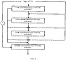
- FIG. 1 is a flowchart of an image denoising method according to the present application.
- the image denoising method is applicable to a scenario for denoising an image, and may be executed by an image denoising apparatus.
- the image denoising apparatus may be implemented in software and/or hardware, or may be integrated in an electronic device.
- the image denoising method of the present application may include operations 101 and 102.
- the image denoising model is a model formed by combining a U-shaped network, a residual network and a dense network.
- the image to be processed may be an image captured by a front end monitoring device, or an image frame in a video captured by the front end monitoring device.
- the image to be processed in the present application may also be an image in other fields, such as a medical image, or the like.
- the image denoising model in the present application may be a pre-trained model.
- the model is a model formed by combining a U-shaped network, a residual network and a dense network.
- the U-shaped network i.e., Unet
- the residual network in the present application refers to a network including a direct mapping part and a residual part, where the direct mapping part and the residual part are subjected to an addition operation.
- the dense network in the present application refers to a network including a direct mapping part and a residual part, where the direct mapping part and the residual part perform channel joining.
- the image denoising model of the present application can, in combination with characteristics of the residual network and the dense network, better utilize deep and shallow features of the image to be processed; and remove noises while reserving details of the image to be processed as much as possible, thereby considering the quality of the denoised image while achieving better denoising performance.
- FIG. 2 is a schematic structural diagram of an image denoising model according to the present application.
- the image denoising model of the present application may include: an input layer, a first convolutional layer, at least one dense residual module, a dense residual block, at least one upsampling module, a second convolutional layer, a third convolutional layer, and an output layer which are connected in sequence.
- a subtraction operation is performed on an output of the input layer and an output of the third convolutional layer, and a result of the subtraction operation is input to an input of the output layer.
- An addition operation is performed on an output of the first convolutional layer and an output of the second convolutional layer, and a result of the addition operation is input to an input of the third convolutional layer.
- the dense residual module includes a first dense residual submodule and a convolution submodule which are connected in sequence
- the upsampling module includes an upsampling submodule and a second dense residual submodule which are connected in sequence.
- An addition operation is performed on an output of the first dense residual submodule and an input of the upsampling submodule.
- 4 dense residual modules may be provided, and 4 upsampling modules may be provided.
- mapping relationship between the dense residual modules and the upsampling modules may be established. According to the mapping relationship, the addition operation is performed on the output of the first dense residual submodule in the dense residual module and the input of the upsampling submodule in the corresponding upsampling module in the mapping relationship.
- the image to be processed input from the input layer has a resolution of N*N, and the number of channels is 3.
- the first convolutional layer has a convolutional kernel of 3 ⁇ 3, and the number of channels becomes 128.
- the convolutional kernel in the convolution submodule is also 3*3, with a span of 2.
- the second convolutional layer and the third convolutional layer each have a convolutional kernel of 3 ⁇ 3.
- the number of channels in the second convolutional layer is 128, and the number of channels in the third convolutional layer is 3.
- FIG. 3 is a schematic structural diagram of a first dense residual submodule in the image denoising model according to the present application.
- the first dense residual submodule may include: a fourth convolutional layer, a fifth convolutional layer, a sixth convolutional layer, and a seventh convolutional layer which are connected in sequence.
- An addition operation is performed on an input of the fourth convolutional layer and an input of the seventh convolutional layer.
- a fusion operation is performed on an input of the fifth convolutional layer and the input of the fourth convolutional layer.
- a fusion operation is performed on an input of the sixth convolutional layer, an output of the fourth convolutional layer, and the input of the fourth convolutional layer.
- a fusion operation is performed on the input of the seventh convolutional layer, the input of the fourth convolutional layer, an output of the fifth convolutional layer, and the output of the fourth convolutional layer.
- the fusion operation in the present application refers to channel joining in a dense network.
- the second dense residual submodule and the dense residual block have the same structure as the first dense residual submodule, and thus are not repeated here.
- the fourth convolutional layer, the fifth convolutional layer, and the sixth convolutional layer each have a convolutional kernel of 3 ⁇ 3.
- the seventh convolutional layer has a convolutional kernel of 1 ⁇ 1.
- M is used to represent the number of channels in the fourth convolutional layer, the fifth convolutional layer, the sixth convolutional layer or the seventh convolutional layer.
- the image denoising method of the present application may include: acquiring an image to be processed, and inputting the image to be processed into an image denoising model to acquire a denoised image.
- the image denoising model is a model formed by combining a U-shaped network, a residual network and a dense network.
- the image denoising model of the present application can, in combination with characteristics of the residual network and the dense network, better utilize deep and shallow features of the image to be processed, and remove noises while reserving details of the image to be processed as much as possible, thereby considering the quality of the denoised image while achieving better denoising performance.
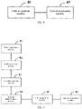
- FIG. 4 is another flowchart of an image denoising method according to the present application. Based on the possible implementation shown in FIG. 1 and various optional solutions, an embodiment of the present application describes in detail how to train the image denoising model. Only operations involved in training the image denoising model are illustrated in the embodiment of the present application. As shown in FIG. 4 , the image denoising method according to the embodiment of the present application may include the following operations 401 to 404.
- the first training noise image and the corresponding first training truth value image may be acquired by actual capturing.
- the first training noise image and the corresponding first training truth value image may be acquired by actually capturing and by means of an adversarial network.
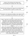
- FIG. 5A is a flowchart of acquiring a first training noise image and a corresponding first training truth value image according to the present application. As shown in FIG. 5A , the acquiring may include the following operations 501 to 505.
- the first preset light source brightness may be 200 lux.
- the camera module is enabled, and denoising algorithm and dead pixel removal algorithm in an image signal processing module are all disabled.
- the camera and the scenario are kept absolutely still during the capturing, and the number of the target images may be 200.
- generating the second training truth value image from the plurality of target images may include determining, according to the plurality of target images, an average image of the plurality of target images, and taking the average image of the plurality of target images as the second training truth value image.
- the plurality of target images may be subjected to operations like dead pixel removal, intensity alignment, or mean value acquisition, to generate a final second training truth value image. This implementation will be described in detail later.
- the second preset light source brightness is lower than the third preset light source brightness, and the third preset light source brightness is lower than the first preset light source brightness.
- the plurality of images captured by randomly adjusting the light source brightness within the range of the second preset light source brightness and the third preset light source brightness are taken as the second training noise images.
- the second preset light source brightness may be 0.1 lux, and the third preset light source brightness may be 100 lux.
- the number of the second training noise images may be 200. While the second training noise images are captured, camera parameters, such as an analog gain and a digital gain, for each captured second training noise image may be recorded.
- the scenario may be changed, and the plurality of target images and the second training noise images may be captured in different scenarios.
- the second training truth value image is generated from the plurality of target images of a same scenario.
- one second training truth value image corresponds to a plurality of second training noise images.
- the adversarial network in the embodiment of the present application may include a generator network and a discriminator network.
- the generator network and the discriminator network in the adversarial network may each be a U-shaped network.
- An initial generator network in the initial adversarial network is configured to generate a noise image
- an initial discriminator network in the initial adversarial network is configured to determine similarity between the noise image output from the initial generator network and an actual second training noise image.
- the initial adversarial network is independently and alternately trained in an iterative manner until convergence.
- the specific process may include the following operations 1 to 3.
- the output probability of the initial discriminator network is a value between 0 and 1, representing a probability of a true or false noise image.
- 0 represents the noise image generated from the generator network
- 1 represents the second training noise image actually acquired.
- N c represents a conditional signal for generating a noise image, including an analog gain and a digital gain of the camera and the second training truth value image
- N f is the noise image generated from the generator network
- N r is the second training noise image actually acquired
- D(*) represents output from the discriminator network
- E(*) represents average.
- a third training truth value image acquired in advance may be input into the adversarial network to acquire a third training noise image output from the generator network of the adversarial network.
- both the second training noise image actually gathered and the third training noise image generated from the adversarial network may be taken as first training noise images for training the image denoising model, and both the second training truth value image and the third training truth value image are taken as the corresponding first training truth value images.
- adjusting when the loss function is greater than a preset threshold, a network architecture and network parameters of the initial image denoising model according to the loss function, determining an updated image denoising model, taking the updated image denoising model as a new initial image denoising model, returning to the operation of inputting the first training noise image into the initial image denoising model to acquire the output result, until the loss function is smaller than or equal to the preset threshold, and determining the image denoising model when the loss function is smaller than or equal to the preset threshold as the image denoising model.
- Operations 402 to 404 show a process of iteratively training the image denoising model.
- the image denoising model based on these first training noise images can significantly improve the denoising performance and the generalization capability of the image denoising model.
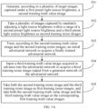
- FIG. 5B is a flowchart of generating a second training truth value image according to the present application. As shown in FIG. 5B , the process of generating the second training truth value image may include the following operations 601 to 604.
- Each pixel point in the average image has a pixel value being an average value of pixel values of pixel points at corresponding positions of all images captured in the rayless environment.
- Operations 601 to 603 show a dead pixel removal process.
- Dead pixels will affect the accuracy in truth value image estimation, because they do not follow the stochastic process of generating noises at normal pixel positions. If an absolute value of a difference between the first pixel value and the second pixel value is greater than a preset first pixel difference threshold, it indicates that the pixel point corresponding to the first pixel value is a defective pixel point.
- the updated value of the first pixel value is determined in a bilinear interpolation method. After all the dead pixels are corrected, an updated target image is formed.
- the target image is taken as an updated target image.
- an average image of a plurality of updated target images may be taken as the second training truth value image.
- operation 604 may specifically include: determining, for each updated target image, an average pixel value of all pixel points in the updated target image; determining, according to the average pixel value of each updated target image, an average value of average pixel values of a plurality of updated target images; discarding an updated target image of which an absolute value of a difference between a corresponding average pixel value and the average value of the average pixel values is greater than a preset second pixel difference threshold, to form filtered updated target images; generating, according to the filtered updated target images, the second training truth value image.
- This implementation achieves intensity alignment of pictures. Due to the inaccuracy of the exposure algorithm, it is still desired to consider small changes in the captured pictures under the same scenario and same brightness.
- the updated target image of which an absolute value of a difference between a corresponding average pixel value and the average value of the average pixel values is greater than a preset second pixel difference threshold is discarded.
- an average value and a variance of the average pixel value of the plurality of updated target images According to the average pixel value of each updated target image, an average value and a variance of the average pixel value of the plurality of updated target images.
- a confidence interval is derived from the average value and the variance, and images outside the confidence interval are then discarded.
- generating, according to the filtered updated target images, the second training truth value image includes: updating, for each filtered updated target image if a pixel value at a first position of the filtered updated target image is smaller than or equal to a preset first pixel threshold or greater than or equal to a preset second pixel threshold, the pixel value at the first position to a pixel value, among pixel values at first positions of all the filtered updated target images, which appears most times, and generating secondary updated filtered target images, where the first pixel threshold is smaller than the second pixel threshold; and determining an average image of all the secondary updated filtered target images as the second training truth value image.
- the preset first pixel threshold may be 0, and the preset second pixel threshold may be 255.
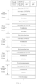
- FIG. 6 is a schematic structural diagram of a generator network in an adversarial network according to the present application.
- the generator network may include: an input layer, a 3-layer first convolution module, a first pooling layer, a 3-layer second convolution module, a second pooling layer, an 8-layer third convolution module, a first upsampling layer, a 3-layer fourth convolution modules, a second upsampling layer, a 3-layer fifth convolution modules, and a convolutional layer which are connected in sequence.
- Each convolution module includes a convolutional layer, a normalization layer, and an activation layer.
- Each convolutional kernel involved in the generator network is 3 ⁇ 3.
- the image resolution and the number of channels in each layer or each module are as shown in the figure.
- the image resolution is 256*256, and the number of channels is 8; in the convolutional layer of the first convolution module, the image resolution is 256*256, and the number of channels is 64; in the convolutional layer of the second convolution module, the image resolution is 128*128, and the number of channels is 128; in the convolutional layer of the third convolution module, the image resolution is 64*64, and the number of channels is 256; in the convolutional layer of the fourth convolution module, the image resolution is 128*128, and the number of channels is 128; and in the convolutional layer of the fifth convolution module, the image resolution is 256*256, and the number of channels is 64.
- FIG. 7 is a schematic structural diagram of a discriminator network in the adversarial network according to the present application.
- the discriminator network may include: an input layer, a 3-layer first convolution modules, a first pooling layer, a 3-layer second convolution modules, a second pooling layer, a 3-layer third convolution modules, a third pooling layer, a 2-layer fourth convolution modules, a fourth pooling layer, a fifth convolution module, a fully-connected layer, and an activation layer which are connected in sequence.
- An activation function of the activation layer may be a Sigmoid function.
- Each convolution module includes a convolutional layer, a normalization layer, and an activation layer.
- Each convolutional kernel involved in the discriminator network is 3 ⁇ 3.
- the image resolution and the number of channels in each layer or each module are as shown in the figure.
- the image resolution is 256*256, and the number of channels is 12; in the convolutional layer of the first convolution module, the image resolution is 256*256, and the number of channels is 64; in the convolutional layer of the second convolution module, the image resolution is 128*128, and the number of channels is 128; in the convolutional layer of the third convolution module, the image resolution is 64*64, and the number of channels is 256; in the convolutional layer of the fourth convolution module, the image resolution is 32*32, and the number of channels is 512; and in the convolutional layer of the fifth convolution module, the image resolution is 16* 16, and the number of channels is 64.
- both the second training noise image actually gathered and the third training noise image generated from the adversarial network may be taken as first training noise images for training the image denoising model, and both the second training truth value image and the third training truth value image are taken as the corresponding first training truth value images.
- FIG. 8 is a schematic structural diagram of an image denoising apparatus according to the present application.
- the image denoising apparatus of the present application may include: a first acquisition module 81 and a second acquisition module 82.
- the first acquisition module 81 may be configured to acquire an image to be processed.
- the second acquisition module 82 may be configured to input the image to be processed into an image denoising model to acquire a denoised image.
- the image denoising model may be a model formed by combining a U-shaped network, a residual network and a dense network.
- the image denoising model may include: an input layer, a first convolutional layer, at least one dense residual module, a dense residual block, at least one upsampling module, a second convolutional layer, a third convolutional layer, and an output layer which are connected in sequence.
- a subtraction operation is performed on an output of the input layer and an output of the third convolutional layer, and a result of the subtraction operation is input to an input of the output layer.
- An addition operation is performed on an output of the first convolutional layer and an output of the second convolutional layer, and a result of the addition operation is input to an input of the third convolutional layer.
- the dense residual module may include a first dense residual submodule and a convolution submodule which are connected in sequence
- the upsampling module may include an upsampling submodule and a second dense residual submodule which are connected in sequence.
- An addition operation is performed on an output of the first dense residual submodule and an input of the upsampling submodule.
- the first dense residual submodule may include: a fourth convolutional layer, a fifth convolutional layer, a sixth convolutional layer, and a seventh convolutional layer which are connected in sequence.
- An addition operation is performed on an input of the fourth convolutional layer and an input of the seventh convolutional layer.
- a fusion operation is performed on an input of the fifth convolutional layer and the input of the fourth convolutional layer.
- a fusion operation is performed on an input of the sixth convolutional layer, an output of the fourth convolutional layer, and the input of the fourth convolutional layer.
- a fusion operation is performed on the input of the seventh convolutional layer, the input of the fourth convolutional layer, an output of the fifth convolutional layer, and the output of the fourth convolutional layer.
- the image denoising apparatus may be configured to execute the image denoising method according to any of the above possible implementations, and the implementation principle and the technical effect of the image denoising apparatus according to the embodiments of the present application are similar thereto, and thus are not repeated here.
- FIG. 9 is another schematic structural diagram of an image denoising apparatus according to the present application. Other modules included in the image denoising apparatus are described in detail below on the basis of the possible implementation shown in FIG. 8 . As shown in FIG. 9 , the image denoising apparatus of the present application may further include the following modules: a third acquisition module 91, a fourth acquisition module 92, a first determination module 93, and a second determination module 94.
- the third acquisition module 91 may be configured to acquire a first training noise image and a corresponding first training truth value image.
- the fourth acquisition module 92 may be configured to input the first training noise image into an initial image denoising model to acquire an output result.
- the first determination module 93 may be configured to determine a loss function according to the output result and the corresponding first training truth value image.
- the second determination module 94 may be configured to, adjust, when the loss function is greater than a preset threshold, a network architecture and network parameters of the initial image denoising model according to the loss function, determine an updated image denoising model, take the updated image denoising model as a new initial image denoising model, return to the operation of inputting the first training noise image into the initial image denoising model to acquire the output result, until the loss function is smaller than or equal to the preset threshold, and determine the image denoising model when the loss function is smaller than or equal to the preset threshold as the image denoising model.
- the image denoising apparatus may be configured to execute the image denoising method according to any of the above possible implementations, and the implementation principle and the technical effect of the image denoising apparatus according to the embodiments of the present application are similar thereto, and thus are not repeated here.
- FIG. 10 is another schematic structural diagram of an image denoising apparatus according to the present application.
- the third acquisition module 91 may include: a generation submodule 911, a first determination submodule 912, a first acquisition submodule 913, a second acquisition submodule 914, and a second determination submodule 915.
- the generation submodule 911 may be configured to generate, according to a plurality of target images captured under a first preset light source brightness, a second training truth value image.
- the generation submodule 911 may be specifically configured to: generate, according to a plurality of images captured in a rayless environment, an average image of the plurality of images; compare, for each target image, a first pixel value of each pixel point in the target image with a second pixel value of a pixel point at a corresponding position in the average image; determine, if an absolute value of a difference between the first pixel value and the second pixel value is greater than a preset first pixel difference threshold, an updated value of the first pixel value in a bilinear interpolation method to form an updated target image; and generate, according to the updated target image, a second training truth value image.
- the generation submodule 911 may be specifically configured to: determine, for each updated target image, an average pixel value of all pixel points in the updated target image; determine, according to the average pixel value of each updated target image, an average value of average pixel values of a plurality of updated target images; discard an updated target image of which an absolute value of a difference between a corresponding average pixel value and the average value of the average pixel values is greater than a preset second pixel difference threshold, to form filtered updated target images; and generate, according to the filtered updated target images, the second training truth value image.
- the generation submodule 911 may be specifically configured to: update, for each filtered updated target image if a pixel value at a first position of the filtered updated target image is smaller than or equal to a preset first pixel threshold or greater than or equal to a preset second pixel threshold, the pixel value at the first position to a pixel value, among pixel values at first positions of all the filtered updated target images, which appears most times, and generate secondary updated filtered target images, where the first pixel threshold is smaller than the second pixel threshold; and determine an average image of all the secondary updated filtered target images as the second training truth value image.
- the first determination submodule 912 may be configured to take a plurality of images captured by randomly adjusting a light source brightness within a range of a second preset light source brightness and a third preset light source brightness as second training noise images.
- the second preset light source brightness is lower than the third preset light source brightness, and the third preset light source brightness is lower than the first preset light source brightness.
- the first acquisition submodule 913 may be configured to train, according to the second training truth value image and the second training noise images, an initial adversarial network to acquire a finally trained adversarial network.
- the first acquisition submodule 913 may be specifically configured to: input normally distributed noises, the second training truth value image, and camera parameters corresponding to any second training noise image into an initial generator network in an initial adversarial network to acquire an output noise image; input the noise image, the second training noise image, camera parameters corresponding to the second training noise image and the second training truth value image into an initial discriminator network in the initial adversarial network to acquire an output probability of the initial discriminator network; and determine, according to the output probability, the camera parameters corresponding to the second training noise image, the second training truth value image, and the noise image, a loss function of the initial discriminator network and a loss function of the initial generator network, alternately return to, when determining that the initial adversarial network is not converged according to the loss function of the initial discriminator network and the loss function of the initial generator network, the operation of inputting the normally distributed noises, the second training truth value image, and the camera parameters corresponding to the second training noise image into the initial generator network in the initial adversarial network to acquire
- the generator network and the discriminator network in the adversarial network may each be a U-shaped network.
- the second acquisition submodule 914 may be configured to input a third training truth value image acquired in advance into the adversarial network to acquire a third training noise image output from a generator network of the adversarial network.
- the second determination submodule 915 may be configured to take both the second training noise image and the third training noise image as first training noise images, and take both the second training truth value image and the third training truth value image as the corresponding first training truth value images.
- the image denoising apparatus of the present application may be configured to implement the image denoising method according to any of the above possible implementations, and the implementation principle and the technical effect of the image denoising apparatus of the present application are similar thereto, and thus are not repeated here.
- FIG. 11 is a schematic structural diagram of an electronic device according to the present application.
- the electronic device may include a processor 111 and a memory 112.
- processors 111 there may be one or more processors 111 in the electronic device, and one processor 111 is shown as an example in FIG. 11 .
- the processor 111 and the memory 112 in the electronic device may be connected via a bus or by other means, and FIG. 11 illustrates the connection by a bus as an example.
- the memory 112 may be configured to store software programs, computer-executable programs, and modules, such as program instructions/modules corresponding to the image denoising method in the embodiments state present application (such as the first acquisition module 81 and the second acquisition module 82 in the image denoising apparatus).
- the processor 111 executes the software programs, instructions and modules stored in the memory 112 to perform various functional applications and data processing of the electronic device, i.e., to implement the image denoising method as described above.
- the memory 112 may mainly include a program storage area and a data storage area.
- the program storage area may store an operating system, or an application program required for at least one function; and the data storage area may store data created according to the use of the electronic device, and the like.
- the memory 112 may include a high speed random access memory, and may further include a non-volatile memory, such as at least one magnetic disk memory device, flash memory device, or other non-volatile solid state memory devices.
- the present application further provides a storage medium containing computer-executable instructions which, when executed by a computer processor, cause the image denoising method to be implemented, the method including: acquiring an image to be processed; and inputting the image to be processed into an image denoising model to acquire a denoised image.
- the image denoising model is a model formed by combining a U-shaped network, a residual network and a dense network.
- the computer-executable instructions are not limited to the above method operations, and may further cause the relevant operations in image denoising method according to any possible implementations of the present application to be implemented.
- the various possible implementations of the present application may be implemented in hardware or dedicated circuits, software, logic or any combination thereof.
- some aspects may be implemented in hardware, while other aspects may be implemented in firmware or software which may be executed by a controller, microprocessor or other computing device, although the application is not limited thereto.
- Embodiments of the present application may be implemented by a data processor of a mobile device executing computer program instructions, for example in a processor entity, or by hardware, or by a combination of software and hardware.
- the computer program instructions may be assembler instructions, instruction set architecture (ISA) instructions, machine instructions, machine-related instructions, microcode, firmware instructions, state setting data, or source codes or object codes written in any combination of one or more programming languages.
- ISA instruction set architecture
- the block diagrams of any logic flow in the figures of the present application may represent program operations, or may represent interconnected logic circuits, modules, and functions, or may represent a combination of program operations and logic circuits, modules, and functions.
- the computer program may be stored on a memory.
- the memory may be of any type suitable to the local technical environment and may be implemented using any suitable data storage technology, such as but not limited to, read-only memories (ROMs), random access memories (RAMs), optical storage devices or systems (digital versatile discs (DVDs), compact discs (CDs)), etc.
- the computer-readable medium may include a non-transitory storage medium.
- the data processor may be of any type suitable to the local technical environment, such as but not limited to, general purpose computers, dedicated computers, microprocessors, digital signal processors (DSPs), application specific integrated circuits (ASICs), field-programmable gate arrays (FGPAs), and processors based on multi-core processor architecture.
- DSPs digital signal processors
- ASICs application specific integrated circuits
- FGPAs field-programmable gate arrays
Landscapes
- Engineering & Computer Science (AREA)
- Physics & Mathematics (AREA)
- Theoretical Computer Science (AREA)
- General Physics & Mathematics (AREA)
- Data Mining & Analysis (AREA)
- Evolutionary Computation (AREA)
- Artificial Intelligence (AREA)
- Biomedical Technology (AREA)
- Biophysics (AREA)
- Computational Linguistics (AREA)
- Health & Medical Sciences (AREA)
- Life Sciences & Earth Sciences (AREA)
- General Health & Medical Sciences (AREA)
- Molecular Biology (AREA)
- Computing Systems (AREA)
- General Engineering & Computer Science (AREA)
- Mathematical Physics (AREA)
- Software Systems (AREA)
- Probability & Statistics with Applications (AREA)
- Image Processing (AREA)
Applications Claiming Priority (2)
| Application Number | Priority Date | Filing Date | Title |
|---|---|---|---|
| CN202010346311.9A CN113643189B (zh) | 2020-04-27 | 2020-04-27 | 图像去噪方法、装置和存储介质 |
| PCT/CN2021/088927 WO2021218765A1 (zh) | 2020-04-27 | 2021-04-22 | 图像去噪方法及装置、电子设备以及存储介质 |
Publications (3)
| Publication Number | Publication Date |
|---|---|
| EP4145384A1 true EP4145384A1 (de) | 2023-03-08 |
| EP4145384A4 EP4145384A4 (de) | 2024-05-15 |
| EP4145384B1 EP4145384B1 (de) | 2026-02-11 |
Family
ID=78332093
Family Applications (1)
| Application Number | Title | Priority Date | Filing Date |
|---|---|---|---|
| EP21795374.4A Active EP4145384B1 (de) | 2020-04-27 | 2021-04-22 | Bildentrauschungsverfahren und -vorrichtung, elektronische vorrichtung und speichermedium |
Country Status (4)
| Country | Link |
|---|---|
| US (1) | US12394023B2 (de) |
| EP (1) | EP4145384B1 (de) |
| CN (1) | CN113643189B (de) |
| WO (1) | WO2021218765A1 (de) |
Cited By (2)
| Publication number | Priority date | Publication date | Assignee | Title |
|---|---|---|---|---|
| CN116630837A (zh) * | 2023-03-13 | 2023-08-22 | 北京邮电大学 | 双阶段视频去噪模型训练方法、视频去噪方法和系统 |
| CN116977650A (zh) * | 2023-07-31 | 2023-10-31 | 西北工业大学深圳研究院 | 图像去噪方法、图像去噪装置、电子设备及存储介质 |
Families Citing this family (38)
| Publication number | Priority date | Publication date | Assignee | Title |
|---|---|---|---|---|
| JP2023041375A (ja) * | 2021-09-13 | 2023-03-24 | キヤノン株式会社 | 情報処理装置、情報処理方法及びプログラム |
| CN114298202B (zh) * | 2021-12-23 | 2025-10-24 | 杭州海康威视数字技术股份有限公司 | 一种图像加密方法、装置、电子设备及存储介质 |
| CN114418873B (zh) * | 2021-12-29 | 2022-12-20 | 英特灵达信息技术(深圳)有限公司 | 一种暗光图像降噪方法及装置 |
| CN114494047B (zh) * | 2022-01-11 | 2024-04-02 | 辽宁师范大学 | 一种基于双增强残差网络的生物图像去噪方法 |
| CN115115531B (zh) * | 2022-01-14 | 2025-10-28 | 长城汽车股份有限公司 | 图像去噪方法、装置、车辆及存储介质 |
| CN116739907A (zh) * | 2022-03-01 | 2023-09-12 | Oppo广东移动通信有限公司 | 图像去噪方法、装置、设备和计算机可读存储介质 |
| CN114757841B (zh) * | 2022-03-30 | 2024-06-25 | 西北核技术研究所 | 一种基于噪声特性的激光诱导荧光图像去噪方法 |
| CN114898113B (zh) * | 2022-04-29 | 2025-12-12 | 际络科技(上海)有限公司 | 一种对象检测方法、装置、电子设备及存储介质 |
| CN114897725B (zh) * | 2022-05-09 | 2025-01-07 | 马上消费金融股份有限公司 | 图像降噪方法、装置、设备及存储介质 |
| CN114724144B (zh) * | 2022-05-16 | 2024-02-09 | 北京百度网讯科技有限公司 | 文本识别方法、模型的训练方法、装置、设备及介质 |
| CN117291824B (zh) * | 2022-06-20 | 2026-03-24 | 北京小米移动软件有限公司 | 图像处理方法、装置、电子设备及存储介质 |
| CN115222667A (zh) * | 2022-06-21 | 2022-10-21 | Oppo广东移动通信有限公司 | 图像处理方法及装置、计算机可读存储介质和电子设备 |
| CN115526857A (zh) * | 2022-09-26 | 2022-12-27 | 深圳先进技术研究院 | 一种pet图像去噪的方法、终端设备及可读存储介质 |
| CN116051408B (zh) * | 2023-01-06 | 2023-10-27 | 郑州轻工业大学 | 一种基于残差自编码的图像深度去噪方法 |
| CN116029946B (zh) * | 2023-03-29 | 2023-06-13 | 中南大学 | 基于异构残差注意神经网络模型的图像去噪方法及系统 |
| CN116915549A (zh) * | 2023-05-18 | 2023-10-20 | 重庆邮电大学 | 一种基于轻量级高效LEU-Net的1-比特大规模MIMO信道估计方法 |
| CN116721023A (zh) * | 2023-05-22 | 2023-09-08 | 北京奕斯伟计算技术股份有限公司 | 图像去噪模型训练方法、图像去噪方法、装置和电子设备 |
| CN116912111A (zh) * | 2023-06-21 | 2023-10-20 | 中国联合网络通信集团有限公司 | 一种图像去噪方法、图像处理模型的训练方法及装置 |
| CN116862903B (zh) * | 2023-07-31 | 2024-06-25 | 梅卡曼德(北京)机器人科技有限公司 | 缺陷检测模型训练方法及装置、缺陷检测方法和电子设备 |
| CN116723412B (zh) * | 2023-08-10 | 2023-11-10 | 四川玉米星球科技有限公司 | 一种照片中背景光影均化方法及文本拍摄扫描系统 |
| CN117197014B (zh) * | 2023-09-12 | 2024-02-20 | 南京诺源医疗器械有限公司 | 一种可降噪的肺部医学图像融合方法、系统和电子设备 |
| CN117315090B (zh) * | 2023-09-27 | 2024-12-13 | 中国科学院自动化研究所 | 基于跨模态风格学习的图像生成方法及装置 |
| CN117291846B (zh) * | 2023-11-27 | 2024-02-27 | 北京大学第三医院(北京大学第三临床医学院) | 一种应用于喉显微外科手术的oct系统及图像去噪方法 |
| CN117351216B (zh) * | 2023-12-05 | 2024-02-02 | 成都宜图智享信息科技有限公司 | 一种基于监督深度学习的图像自适应去噪方法 |
| CN117392615B (zh) * | 2023-12-12 | 2024-03-15 | 南昌理工学院 | 一种基于监控视频的异常识别方法及系统 |
| CN117830079B (zh) * | 2023-12-27 | 2024-07-26 | 北京智象未来科技有限公司 | 真实图片预测方法、装置、设备、存储介质 |
| CN117474797B (zh) * | 2023-12-28 | 2024-03-19 | 南京信息工程大学 | 一种多尺度互补学习的图像去噪方法及装置 |
| CN117495687B (zh) * | 2023-12-29 | 2024-04-02 | 清华大学深圳国际研究生院 | 一种水下图像增强方法 |
| CN117541501B (zh) * | 2024-01-09 | 2024-05-31 | 清华大学 | 扫描光场自监督网络去噪方法、装置、电子设备及介质 |
| CN117934944A (zh) * | 2024-01-24 | 2024-04-26 | 广东工业大学 | 一种基于裁剪量化的图像分类方法、装置及设备 |
| CN117726542B (zh) * | 2024-02-18 | 2024-06-21 | 北京理工大学 | 基于扩散模型的可控噪声去除方法及系统 |
| CN117876943B (zh) * | 2024-03-12 | 2024-08-20 | 荣耀终端有限公司 | 一种图像处理方法、图像增强模型的训练方法及电子设备 |
| CN118229818B (zh) * | 2024-04-10 | 2025-05-13 | 国家卫星气象中心(国家空间天气监测预警中心) | 一种基于气象卫星数据的合成云图生成方法及系统 |
| CN118365954B (zh) * | 2024-05-14 | 2025-04-11 | 广东电网有限责任公司 | 钢筋绑扎质量的确定方法、装置、处理器和电子设备 |
| CN118608417B (zh) * | 2024-05-31 | 2025-01-24 | 重庆交通大学 | 基于深度学习的遥感图像复合噪声去除方法 |
| CN118279181B (zh) * | 2024-05-31 | 2024-08-27 | 杭州海康威视数字技术股份有限公司 | 可调参图像复原模型的训练方法和可调参的图像复原方法 |
| CN118898552B (zh) * | 2024-10-08 | 2025-02-28 | 浙江大学滨江研究院 | 基于改进聚类的多阶段oct图像去噪方法、设备和存储介质 |
| CN119992307B (zh) * | 2025-04-17 | 2026-02-13 | 上海达华测绘科技有限公司 | 基于声呐图像的水下目标检测方法、装置、设备及介质 |
Family Cites Families (15)
| Publication number | Priority date | Publication date | Assignee | Title |
|---|---|---|---|---|
| EP3616097A4 (de) * | 2017-04-25 | 2021-01-13 | The Board of Trustees of the Leland Stanford Junior University | Dosisreduktion für die medizinische bildgebung unter verwendung von tiefen neuronalen faltungsnetzwerken |
| US10698063B2 (en) * | 2017-11-01 | 2020-06-30 | Siemens Healthcare Gmbh | Motion artifact reduction of magnetic resonance images with an adversarial trained network |
| US11756160B2 (en) * | 2018-07-27 | 2023-09-12 | Washington University | ML-based methods for pseudo-CT and HR MR image estimation |
| US11164067B2 (en) * | 2018-08-29 | 2021-11-02 | Arizona Board Of Regents On Behalf Of Arizona State University | Systems, methods, and apparatuses for implementing a multi-resolution neural network for use with imaging intensive applications including medical imaging |
| CN110232361B (zh) * | 2019-06-18 | 2021-04-02 | 中国科学院合肥物质科学研究院 | 基于三维残差稠密网络的人体行为意图识别方法与系统 |
| CN110473154B (zh) * | 2019-07-31 | 2021-11-16 | 西安理工大学 | 一种基于生成对抗网络的图像去噪方法 |
| CN110599409B (zh) * | 2019-08-01 | 2022-02-22 | 西安理工大学 | 基于多尺度卷积组与并行的卷积神经网络图像去噪方法 |
| CN110443867B (zh) * | 2019-08-01 | 2022-06-10 | 太原科技大学 | 基于生成对抗网络的ct图像超分辨率重构方法 |
| CN110610464A (zh) * | 2019-08-15 | 2019-12-24 | 天津中科智能识别产业技术研究院有限公司 | 一种基于稠密残差神经网络的人脸图像超分辨率方法 |
| CN110782395B (zh) * | 2019-10-28 | 2024-02-09 | 西安电子科技大学 | 图像处理方法及装置、电子设备和计算机可读存储介质 |
| CN110910329B (zh) * | 2019-11-27 | 2022-09-02 | 中国科学技术大学 | 一种以需求为导向的图像去噪方法 |
| US11508037B2 (en) * | 2020-03-10 | 2022-11-22 | Samsung Electronics Co., Ltd. | Systems and methods for image denoising using deep convolutional networks |
| US11948274B1 (en) * | 2021-01-05 | 2024-04-02 | Pixar | Deep learned super resolution for feature film production |
| US20230419447A1 (en) * | 2022-06-23 | 2023-12-28 | Bitmovin Gmbh | Lightweight Dense Residual Network for Video Super-Resolution on Mobile Devices |
| US20240062332A1 (en) * | 2022-08-12 | 2024-02-22 | Beth Israel Deaconess Medical Center, Inc. | System and method for improving sharpness of magnetic resonance images using a deep learning neural network |
-
2020
- 2020-04-27 CN CN202010346311.9A patent/CN113643189B/zh active Active
-
2021
- 2021-04-22 WO PCT/CN2021/088927 patent/WO2021218765A1/zh not_active Ceased
- 2021-04-22 EP EP21795374.4A patent/EP4145384B1/de active Active
- 2021-04-22 US US17/921,271 patent/US12394023B2/en active Active
Cited By (2)
| Publication number | Priority date | Publication date | Assignee | Title |
|---|---|---|---|---|
| CN116630837A (zh) * | 2023-03-13 | 2023-08-22 | 北京邮电大学 | 双阶段视频去噪模型训练方法、视频去噪方法和系统 |
| CN116977650A (zh) * | 2023-07-31 | 2023-10-31 | 西北工业大学深圳研究院 | 图像去噪方法、图像去噪装置、电子设备及存储介质 |
Also Published As
| Publication number | Publication date |
|---|---|
| US12394023B2 (en) | 2025-08-19 |
| WO2021218765A1 (zh) | 2021-11-04 |
| EP4145384B1 (de) | 2026-02-11 |
| CN113643189B (zh) | 2025-01-10 |
| EP4145384A4 (de) | 2024-05-15 |
| US20230230206A1 (en) | 2023-07-20 |
| CN113643189A (zh) | 2021-11-12 |
Similar Documents
| Publication | Publication Date | Title |
|---|---|---|
| EP4145384B1 (de) | Bildentrauschungsverfahren und -vorrichtung, elektronische vorrichtung und speichermedium | |
| US12112248B2 (en) | System and method for end-to-end differentiable joint image refinement and perception | |
| CN110428366B (zh) | 图像处理方法和装置、电子设备、计算机可读存储介质 | |
| US11457138B2 (en) | Method and device for image processing, method for training object detection model | |
| Fan et al. | Dual refinement underwater object detection network | |
| EP3951702B1 (de) | Verfahren zum trainieren eines bildverarbeitungsmodells, bildverarbeitungsverfahren, netzwerkvorrichtung und speichermedium | |
| EP3798975B1 (de) | Verfahren und vorrichtung zur erkennung einer person, elektronische vorrichtung und computerlesbares speichermedium | |
| CN110473185B (zh) | 图像处理方法和装置、电子设备、计算机可读存储介质 | |
| CN112581379B (zh) | 图像增强方法以及装置 | |
| CN113766125B (zh) | 对焦方法和装置、电子设备、计算机可读存储介质 | |
| JP2019071056A (ja) | 映像イメージをセグメンテーションする方法及びこれを利用した装置 | |
| WO2020259474A1 (zh) | 追焦方法、装置、终端设备、计算机可读存储介质 | |
| CN112435278B (zh) | 一种基于动态目标检测的视觉slam方法及装置 | |
| CN111382647A (zh) | 一种图片处理方法、装置、设备及存储介质 | |
| CN112771843A (zh) | 信息处理方法、装置和成像系统 | |
| CN112330576B (zh) | 车载鱼眼摄像头畸变矫正方法、装置、设备及存储介质 | |
| CN117495919A (zh) | 一种基于遮挡物体检测及运动连续性的光流估计方法 | |
| US20240037985A1 (en) | Cascaded detection of facial attributes | |
| KR20220089602A (ko) | 무보정 광각 이미지 기반 가변 합성곱 신경망 학습 방법 및 장치 | |
| CN116091337B (zh) | 一种基于事件信号神经编码方式的图像增强方法及装置 | |
| CN110399823B (zh) | 主体跟踪方法和装置、电子设备、计算机可读存储介质 | |
| CN116797471B (zh) | 一种基于深度学习的水下目标图像检测方法和系统 | |
| CN117218109A (zh) | 车辆侧向拼接图像完整度检测方法、系统、设备和介质 | |
| WO2024082602A1 (zh) | 一种端到端视觉里程计方法及装置 | |
| CN117395513A (zh) | 一种基于非同源双目相机的自动曝光方法、设备及存储介质 |
Legal Events
| Date | Code | Title | Description |
|---|---|---|---|
| STAA | Information on the status of an ep patent application or granted ep patent |
Free format text: STATUS: THE INTERNATIONAL PUBLICATION HAS BEEN MADE |
|
| PUAI | Public reference made under article 153(3) epc to a published international application that has entered the european phase |
Free format text: ORIGINAL CODE: 0009012 |
|
| STAA | Information on the status of an ep patent application or granted ep patent |
Free format text: STATUS: REQUEST FOR EXAMINATION WAS MADE |
|
| 17P | Request for examination filed |
Effective date: 20221107 |
|
| AK | Designated contracting states |
Kind code of ref document: A1 Designated state(s): AL AT BE BG CH CY CZ DE DK EE ES FI FR GB GR HR HU IE IS IT LI LT LU LV MC MK MT NL NO PL PT RO RS SE SI SK SM TR |
|
| DAV | Request for validation of the european patent (deleted) | ||
| DAX | Request for extension of the european patent (deleted) | ||
| A4 | Supplementary search report drawn up and despatched |
Effective date: 20240415 |
|
| RIC1 | Information provided on ipc code assigned before grant |
Ipc: G06T 5/70 20240101ALI20240409BHEP Ipc: G06T 5/60 20240101ALI20240409BHEP Ipc: G06N 3/08 20060101ALI20240409BHEP Ipc: G06N 3/0464 20230101ALI20240409BHEP Ipc: G06N 3/045 20230101ALI20240409BHEP Ipc: G06T 5/00 20060101AFI20240409BHEP |
|
| RAP3 | Party data changed (applicant data changed or rights of an application transferred) |
Owner name: SANECHIPS TECHNOLOGY CO., LTD. |
|
| REG | Reference to a national code |
Ref country code: DE Ref legal event code: R079 Free format text: PREVIOUS MAIN CLASS: G06T0005000000 Ipc: G06N0003047000 Ref country code: DE Ref legal event code: R079 Ref document number: 602021047795 Country of ref document: DE Free format text: PREVIOUS MAIN CLASS: G06T0005000000 Ipc: G06N0003047000 |
|
| GRAP | Despatch of communication of intention to grant a patent |
Free format text: ORIGINAL CODE: EPIDOSNIGR1 |
|
| STAA | Information on the status of an ep patent application or granted ep patent |
Free format text: STATUS: GRANT OF PATENT IS INTENDED |
|
| RIC1 | Information provided on ipc code assigned before grant |
Ipc: G06N 3/047 20230101AFI20251121BHEP Ipc: G06N 3/0475 20230101ALI20251121BHEP Ipc: G06N 3/084 20230101ALI20251121BHEP Ipc: G06N 3/094 20230101ALI20251121BHEP Ipc: G06T 5/60 20240101ALI20251121BHEP Ipc: G06T 5/70 20240101ALI20251121BHEP Ipc: G06N 3/0464 20230101ALI20251121BHEP Ipc: G06N 3/045 20230101ALI20251121BHEP |
|
| GRAS | Grant fee paid |
Free format text: ORIGINAL CODE: EPIDOSNIGR3 |
|
| INTG | Intention to grant announced |
Effective date: 20251205 |
|
| GRAA | (expected) grant |
Free format text: ORIGINAL CODE: 0009210 |
|
| STAA | Information on the status of an ep patent application or granted ep patent |
Free format text: STATUS: THE PATENT HAS BEEN GRANTED |
|
| GRAL | Information related to payment of fee for publishing/printing deleted |
Free format text: ORIGINAL CODE: EPIDOSDIGR3 |
|
| GRAS | Grant fee paid |
Free format text: ORIGINAL CODE: EPIDOSNIGR3 |
|
| AK | Designated contracting states |
Kind code of ref document: B1 Designated state(s): AL AT BE BG CH CY CZ DE DK EE ES FI FR GB GR HR HU IE IS IT LI LT LU LV MC MK MT NL NO PL PT RO RS SE SI SK SM TR |
|
| REG | Reference to a national code |
Ref country code: CH Ref legal event code: F10 Free format text: ST27 STATUS EVENT CODE: U-0-0-F10-F00 (AS PROVIDED BY THE NATIONAL OFFICE) Effective date: 20260211 Ref country code: GB Ref legal event code: FG4D |
|
| REG | Reference to a national code |
Ref country code: DE Ref legal event code: R096 Ref document number: 602021047795 Country of ref document: DE |
|
| REG | Reference to a national code |
Ref country code: IE Ref legal event code: FG4D |