EP4145376A1 - Electric power contract system and electric power contract method - Google Patents
Electric power contract system and electric power contract method Download PDFInfo
- Publication number
- EP4145376A1 EP4145376A1 EP20932873.1A EP20932873A EP4145376A1 EP 4145376 A1 EP4145376 A1 EP 4145376A1 EP 20932873 A EP20932873 A EP 20932873A EP 4145376 A1 EP4145376 A1 EP 4145376A1
- Authority
- EP
- European Patent Office
- Prior art keywords
- electric power
- line
- flow
- risk
- agreement
- Prior art date
- Legal status (The legal status is an assumption and is not a legal conclusion. Google has not performed a legal analysis and makes no representation as to the accuracy of the status listed.)
- Withdrawn
Links
Images








Classifications
-
- G—PHYSICS
- G06—COMPUTING OR CALCULATING; COUNTING
- G06Q—INFORMATION AND COMMUNICATION TECHNOLOGY [ICT] SPECIALLY ADAPTED FOR ADMINISTRATIVE, COMMERCIAL, FINANCIAL, MANAGERIAL OR SUPERVISORY PURPOSES; SYSTEMS OR METHODS SPECIALLY ADAPTED FOR ADMINISTRATIVE, COMMERCIAL, FINANCIAL, MANAGERIAL OR SUPERVISORY PURPOSES, NOT OTHERWISE PROVIDED FOR
- G06Q10/00—Administration; Management
- G06Q10/06—Resources, workflows, human or project management; Enterprise or organisation planning; Enterprise or organisation modelling
- G06Q10/063—Operations research, analysis or management
-
- G—PHYSICS
- G06—COMPUTING OR CALCULATING; COUNTING
- G06Q—INFORMATION AND COMMUNICATION TECHNOLOGY [ICT] SPECIALLY ADAPTED FOR ADMINISTRATIVE, COMMERCIAL, FINANCIAL, MANAGERIAL OR SUPERVISORY PURPOSES; SYSTEMS OR METHODS SPECIALLY ADAPTED FOR ADMINISTRATIVE, COMMERCIAL, FINANCIAL, MANAGERIAL OR SUPERVISORY PURPOSES, NOT OTHERWISE PROVIDED FOR
- G06Q30/00—Commerce
- G06Q30/02—Marketing; Price estimation or determination; Fundraising
- G06Q30/0201—Market modelling; Market analysis; Collecting market data
-
- G—PHYSICS
- G06—COMPUTING OR CALCULATING; COUNTING
- G06Q—INFORMATION AND COMMUNICATION TECHNOLOGY [ICT] SPECIALLY ADAPTED FOR ADMINISTRATIVE, COMMERCIAL, FINANCIAL, MANAGERIAL OR SUPERVISORY PURPOSES; SYSTEMS OR METHODS SPECIALLY ADAPTED FOR ADMINISTRATIVE, COMMERCIAL, FINANCIAL, MANAGERIAL OR SUPERVISORY PURPOSES, NOT OTHERWISE PROVIDED FOR
- G06Q40/00—Finance; Insurance; Tax strategies; Processing of corporate or income taxes
- G06Q40/04—Trading; Exchange, e.g. stocks, commodities, derivatives or currency exchange
-
- G—PHYSICS
- G06—COMPUTING OR CALCULATING; COUNTING
- G06Q—INFORMATION AND COMMUNICATION TECHNOLOGY [ICT] SPECIALLY ADAPTED FOR ADMINISTRATIVE, COMMERCIAL, FINANCIAL, MANAGERIAL OR SUPERVISORY PURPOSES; SYSTEMS OR METHODS SPECIALLY ADAPTED FOR ADMINISTRATIVE, COMMERCIAL, FINANCIAL, MANAGERIAL OR SUPERVISORY PURPOSES, NOT OTHERWISE PROVIDED FOR
- G06Q50/00—Information and communication technology [ICT] specially adapted for implementation of business processes of specific business sectors, e.g. utilities or tourism
- G06Q50/06—Energy or water supply
-
- H—ELECTRICITY
- H02—GENERATION; CONVERSION OR DISTRIBUTION OF ELECTRIC POWER
- H02J—ELECTRIC POWER NETWORKS; CIRCUIT ARRANGEMENTS OR SYSTEMS FOR SUPPLYING OR DISTRIBUTING ELECTRIC POWER; SYSTEMS FOR STORING ELECTRIC ENERGY
- H02J2103/00—Details of circuit arrangements for mains or AC distribution networks
- H02J2103/30—Simulating, planning, modelling, reliability check or computer assisted design [CAD] of electric power networks
-
- H—ELECTRICITY
- H02—GENERATION; CONVERSION OR DISTRIBUTION OF ELECTRIC POWER
- H02J—ELECTRIC POWER NETWORKS; CIRCUIT ARRANGEMENTS OR SYSTEMS FOR SUPPLYING OR DISTRIBUTING ELECTRIC POWER; SYSTEMS FOR STORING ELECTRIC ENERGY
- H02J2103/00—Details of circuit arrangements for mains or AC distribution networks
- H02J2103/30—Simulating, planning, modelling, reliability check or computer assisted design [CAD] of electric power networks
- H02J2103/35—Grid-level management of power transmission or distribution systems, e.g. load flow analysis or active network management
-
- H—ELECTRICITY
- H02—GENERATION; CONVERSION OR DISTRIBUTION OF ELECTRIC POWER
- H02J—ELECTRIC POWER NETWORKS; CIRCUIT ARRANGEMENTS OR SYSTEMS FOR SUPPLYING OR DISTRIBUTING ELECTRIC POWER; SYSTEMS FOR STORING ELECTRIC ENERGY
- H02J3/00—Circuit arrangements for AC mains or AC distribution networks
- H02J3/008—Circuit arrangements for power supply or distribution technologies responsive to energy trading
Definitions
- the present invention relates to evaluation of the amount of electric power flowing through a line facility of an electric power line.
- Patent Document 1 suggests an electric power transaction intermediation system by which, in calculating an agreement result from bidding information about trading of electric power, consideration is given to line constraint such as constraint on inter-regional interconnection to calculate an agreement result not deviating from the line constraint.
- Patent Document 1 Japanese Patent Application Laid-Open JP 2006 - 215 758 A
- An electric power generation operator or a retail operator (these will be called an "operator” collectively) is obligated to pay a penalty if there is alienation between the amount of electric power actually generated or the amount of retail electric power sold and an agreement result, so that it has incentive to generate electric power or sell retail electric power in conformity with the agreement result.
- the electric power transaction intermediation system of Patent Document 1 is based on the assumption that a player to trade electric power is an operator, so that no serious alienation occurs between the agreement result and electric power actually flowing through a line.
- the present invention has been made to solve the above-describe problem, and is intended to reduce the occurrence of breakdown of a line facility due to variation of electric power actually flowing through a line from an agreement result.
- An electric power agreement system is an electric power agreement system that evaluates a flow plan for an electric power line.
- the electric power line includes at least one line facility. At least one customer is connected to each line facility.
- the electric power agreement system includes: an agreement result calculation unit that calculates an agreement result including the amount of electric power to be traded and an electric power unit price about each customer; a flow achievement calculation unit that calculates a total of actual numbers of the amount of surplus electric power about the customer connected to the line facility as a flow achievement for the line facility individually; a flow plan calculation unit that calculates a total value of the amounts of electric power to be traded in the agreement result about the customer connected to the line facility as the flow plan for the line facility individually; a risk calculation unit that calculates a variation of the flow achievement from the flow plan assumed in the future as a risk for the line facility individually on the basis of a variation of the flow achievement from the flow plan in the past; and a line constraint evaluation unit that determines for the line facility individually whether a risk-considered flow plan obtained by adding the risk to the flow plan fulfills line constraint defined on the line facility.
- the electric power agreement system of the present invention is capable of evaluating the line constraint while giving consideration to the risk of variation of the flow achievement from the flow plan.
- the electric power agreement system of the present invention is capable of evaluating the line constraint while giving consideration to the risk of variation of the flow achievement from the flow plan.
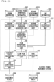
- FIG. 1 is a configuration diagram of an electric power agreement system 201 according to a first embodiment.
- the electric power agreement system 201 is to make an agreement on trading of electric power with each customer of an electric power line and to determine whether a flow plan fulfills line constraint on the basis of an agreement result 1006.
- the electric power agreement system 201 includes a bidding information acquisition unit 101, an electric power generation achievement acquisition unit 102, a demand achievement acquisition unit 103, a line information acquisition unit 104, a surplus achievement calculation unit 105, a flow achievement calculation unit 106, a flow plan calculation unit 107, a risk calculation unit 108, an agreement result calculation unit 109, and a line constraint evaluation unit 110.
- the bidding information acquisition unit 101 acquires bidding information 1001 from each customer.
- the electric power generation achievement acquisition unit 102 acquires electric power generation achievement information 1002 about each customer.
- the demand achievement acquisition unit 103 acquires a demand achievement of each customer.
- the line information acquisition unit 104 acquires line information 1004 about an electric power line.
- the surplus achievement calculation unit 105 calculates a surplus achievement of each customer.
- the flow achievement calculation unit 106 calculates a flow achievement of the line facility individually.
- the flow plan calculation unit 107 calculates a flow plan for the line facility individually.
- the risk calculation unit 108 calculates an assumed variation of the flow achievement from the flow plan as a risk for the line facility individually.
- the agreement result calculation unit 109 calculates the agreement result 1006 from bidding information about each customer according to a blind single price auction system.
- the line constraint evaluation unit 110 determines for the line facility individually whether the flow plan fulfills line constraint while giving consideration to the risk.
- FIG. 2 shows an electric power line to be evaluated in terms of line constraint by the electric power agreement system 201.
- three transformers 1, 2, and 3 are connected to one feeder.
- a customer 1-1, a customer 2-1, and a customer 3-1 are connected to the transformers 1, 2, and 3 respectively.
- one to generate electric power and to sell surplus electric power and one to purchase demanded electric power are not particularly distinguished from each other but are simply called customers.
- the electric power agreement system 201 is owned and managed by a retail operator. Each customer has a retail contract with the retail operator.
- the electric power line in FIG. 2 is shown as an example.
- a line facility connected to the electric power line can be at least one, and a customer connected to one line facility can be at least one.
- Each customer transmits bidding information to the electric power agreement system 201 through a home energy management system (HEMS) owned by this customer, and the electric power agreement system 201 performs agreement processing on the basis of the received bidding information.
- HEMS home energy management system
- a PC or a smart meter may be responsible for transmission of the bidding information from each customer to the electric power agreement system 201 instead of the HEMS, as long as it includes a communication unit, a storage unit, and a processor.
- a transaction target of the agreement processing is the amount of electric power in positive 30 minutes.
- the positive 30 minutes mean a period from X o'clock to X thirty or from X thirty to (X + 1) o'clock.
- X is an optional natural number.
- a market is to be opened by the start time of positive 30 minutes as a transaction target, and the electric power agreement system 201 performs the agreement processing at the start time.
- bedding is permitted until 2019/1/1 00:00 and the agreement processing is performed on 2019/1/1 00:00.
- the blind single price auction system is used for the agreement.
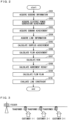
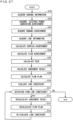
- FIG. 3 is a flowchart showing the operation of the electric power agreement system 201.
- the operation of the electric power agreement system 201 will be described on the basis of the flowchart in FIG. 3 while the amount of electric power from 2019/1/1 00:00 to 2019/1/1 00:30 is an example of a transaction target.
- the electric power agreement system 201 calculates the agreement result 1006 on 2019/1/1 00:00, and determines the presence or absence of deviation from line constraint by giving consideration to the risk that the amount of electric power actually flowing through a line will deviate from the agreement result 1006.
- the bidding information acquisition unit 101 acquires the bidding information 1001 about each customer (step S101).
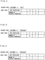
- FIGS. 4 to 6 show examples of the bidding information 1001.
- the bidding information 1001 includes a header part and a body part.
- the header part of the bidding information 1001 includes identification information about a customer such as a customer number and an indication of sale or purchase.
- the indication of sale or purchase indicates whether bidding is for sale or for purchase.
- FIG. 4 shows the bidding information 1001 about sale about the customer 1-1.
- FIG. 5 shows the bidding information 1001 about purchase about the customer 2-1.
- FIG. 6 shows the bidding information 1001 about purchase about the customer 3-1.
- the body part of the bidding information 1001 has a first row indicating a unit price ( ⁇ /kWh) and a second row indicating the amount of electric power (kWh).
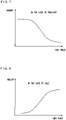
- FIG. 7 shows the body part of the bidding information 1001 about purchase in the form of a graph with a horizontal axis indicating a unit price and a vertical axis indicating an amount.
- FIG. 8 shows the body part of the bidding information 1001 about sale in the form of a graph prepared in the same way.
- the body part of the bidding information 1001 is generally drawn in a downward sloping graph in the case of purchase and is drawn in an upward sloping graph in the case of sale.
- the electric power generation achievement acquisition unit 102 acquires the electric power generation achievement information 1002 indicating an electric power generation achievement of each customer (step S 102).
- the electric power generation achievement means an actual number of the amount of electric power actually generated by a customer.
- FIG. 9 shows an example of the electric power generation achievement information 1002 about the customer 2-1.
- the electric power generation achievement information 1002 includes a header part and a body part.
- the header part of the electric power generation achievement information 1002 includes a customer number.
- the body part of the electric power generation achievement information 1002 has a first row indicting a time zone of positive 30 minutes and a second row indicating the amount of electric power (kWh) corresponding to the electric power generation achievement.
- the demand achievement acquisition unit 103 acquires demand achievement information 1003 indicating a demand achievement of each customer (step S103).
- the demand achievement means an actual number of the amount of electric power actually consumed by a customer.
- FIG. 10 shows an example of the demand achievement information 1003 about the customer 2-1.
- the demand achievement information 1003 includes a header part and a body part.
- the header part includes a customer number.
- the body part has a first row indicating a time zone of positive 30 minutes and a second row indicating the amount of electric power (kWh) corresponding to the demand achievement.
- the line information acquisition unit 104 acquires the line information 1004 (step S104).
- the line information 1004 is information about an electric power line to which the electric power agreement system 201 is applied, and includes a line topology indicating the configuration of the electric power line and information about constraint on a line facility of the electric power line (this will be called "facility constraint information").
- FIG. 11 shows an example of the line topology.
- the line topology in FIG. 11 means that the transformers 1, 2, and 3 are connected to a feeder, the customer 1-1 is connected to the transformer 1, the customer 2-1 is connected to the transformer 2, and the customer 3-1 is connected to the transformer 3.
- FIG. 12 shows an example of the facility constraint information.
- the facility constraint information has a first row indicating identification information about a line facility such as a line facility number and a second row indicating capacity constraint.
- the capacity constraint indicates an upper permissible value of the amount of electric power (including a reverse flow) to flow through the line facility.
- the amount of electric power to flow through the transformer 1 is constrained to be equal to or less than 22 (kWh)
- the amount of electric power to flow through the transformer 2 is constrained to be equal to or less than 20 (kWh)
- the amount of electric power to flow through the transformer 3 is constrained to be equal to or less than 21 (kWh).
- the surplus achievement calculation unit 105 calculates a surplus achievement (step S105).
- the surplus achievement means an actual number of the amount of electric power that becomes a surplus for a customer and is calculated by subtracting a demand achievement from an electric power generation achievement for each time zone.
- FIG. 13 shows an example of the surplus achievement information indicating the surplus achievement.
- the surplus achievement information includes a header part and a body part.
- the header part of the surplus achievement information includes a customer number.
- the body part of the surplus achievement information has a first row indicating a time zone of positive 30 minutes and a second row indicating the amount of electric power (kWh) corresponding to the surplus achievement.
- a positive value of the surplus achievement means a reverse flow and a negative value thereof means a forward flow.
- the flow achievement calculation unit 106 calculates a flow achievement of each line facility on the basis of the line information 1004 and a surplus achievement in the past (step S106).
- the flow achievement means an actual number of the amount of electric power having flowed through each line facility.
- FIG. 14 shows an example of the flow achievement information indicating the flow achievement. As shown in FIG. 14 , the flow achievement information includes a header part and a body part.
- the header part of the flow achievement information indicates identification information about a line facility such as a line facility number.
- the body part of the flow achievement information has a first row indicating a time zone of positive 30 minutes and a second row indicating the amount of electric power (kWh) of the flow achievement.
- the flow achievement calculation unit 106 determines a total value of surplus achievements of a customer connected to each line facility to be the flow achievement.
- the flow achievement calculation unit 106 sees that the customer 2-1 is connected to the transformer 2 on the basis of the line information, and acquires a surplus achievement of the customer 2-1 from the surplus achievement calculation unit 105. Then, the flow achievement calculation unit 106 determines this surplus achievement of the customer 2-1 to be the flow achievement of the transformer 2.
- the risk calculation unit 108 calculates a variation of a flow achievement from a flow plan assumed in the future as a risk (step S107).
- the flow plan means the amount of electric power to flow through each line facility if surplus electric power of each consumer conforms to the agreement result 1006 and is calculated in step S 109 described later.
- FIG. 15 shows an example of flow plan information indicating the flow plan in the past.
- the flow plan information includes a header part and a body part.
- the header part of the flow plan information indicates identification information about a line facility such as a line facility number.
- the body part of the flow plan information has a first row indicating a time zone of positive 30 minutes and a second row indicating the amount of electric power (kWh) corresponding to the flow plan.
- the evaluation index 1005 is an index indicating to which extent a variation of a flow achievement from a flow plan in the past is to be calculated as a risk.
- FIG. 16 shows an example of the evaluation index 1005.
- the evaluation index 1005 shows "worst case in the past.”
- the risk calculation unit 108 calculates a variation occurring in the worst case in the past, specifically, calculates a maximum of a variation of the flow achievement from the flow plan in the past as a risk.
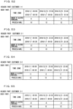
- FIGS. 17 to 19 show examples of risk information indicating a risk.
- the risk information includes a header part and a body part.
- the header part of the risk information indicates identification information about a line facility such as a line facility number.
- the body part of the risk information has a first row indicating a time zone of positive 30 minutes of any date, a second row indicating an upward risk, and a third row indicating a downward risk.
- the upward risk shows a maximum of a value (determined by subtracting a flow plan from a flow achievement) in the past in the time zone of the first row. Specifically, the upward risk shows a variation determined when the flow achievement varied most in the past toward a value exceeding the flow plan. However, if the flow achievement did not exceed the flow plan in the past, the upward risk is determined to be 0.
- the downward risk shows a maximum of a value (determined by subtracting a flow plan from a flow achievement) in the past in the time zone of the first row. Specifically, the downward risk shows a variation determined when the flow achievement varied most in the past toward a value falling under the flow plan. However, if the flow achievement did not fall under the flow plan in the past, the downward risk is determined to be 0.
- a risk of the transformer 2 in a time zone from 00:00 to 00:30 will be described using the flow achievement information shown in FIG. 14 and the flow plan information shown in FIG. 15 as examples.
- flow achievements on 2018/12/29, 2018/12/30, and 2018/12/31 are 6 (kWh), 5 (kWh), and -2 (kWh) respectively.
- flow plans for 2018/12/29, 2018/12/30, and 2018/12/31 in the same time zone are 1 (kWh), 2 (kWh), and 3 (kWh) respectively.
- the risk occurring in the situation where the evaluation index 1005 is "worst case in the past" is as has been described above.
- the evaluation index 1005 may alternatively be "possibility of equal to or greater than 90 %," for example.
- the risk calculation unit 108 calculates a variation as a risk that is to be determined if a flow achievement is assumed to vary from a flow plan with a probability of equal to or greater than 90 % based on data in the past.
- the risk calculation unit 108 determines a maximum and a minimum in this interval to be an upward risk and a downward risk respectively.
- a confidential interval to be considered is not limited to the 90 % confidential interval but can be a confidential interval of any percentage.
- the agreement result calculation unit 109 calculates the agreement result 1006 from the bidding information 1001 using the blind single price auction system (step S108).
- FIGS. 20 to 22 show examples of agreement information indicating the agreement result 1006.
- the agreement information includes a header part and a body part.
- the header part of the agreement information indicates a customer number.
- FIG. 20 shows agreement information about the customer 1-1.
- FIG. 21 shows agreement information about the customer 2-1.
- FIG. 22 shows agreement information about the customer 3-1.
- the body part of the agreement information has a first row indicting a time zone of positive 30 minutes, a second row indicating an agreed amount of electric power (kWh), and a third row indicating an agreed price ( ⁇ /kWh).
- the flow plan calculation unit 107 calculates a flow plan on the basis of the agreement result 1006 calculated in step S108 (step S109).
- the flow plan means a value of the amount of electric power intended to flow through each line facility and is a total value of agreed amounts of electric power for a customer connected to each line facility.
- FIGS. 23 to 25 show examples of flow plan information indicating the flow plan. As shown in FIGS. 23 to 25 , the flow plan information includes a header part and a body part.
- the header part of the flow plan information indicates a line facility number.
- the body part of the flow plan information has a first row indicting a time zone of positive 30 minutes and a second row indicating the amount of electric power (kWh) corresponding to the flow plan.
- FIG. 23 shows flow plan information about the transformer 1.
- FIG. 24 shows flow plan information about the transformer 2.
- FIG. 25 shows flow plan information about the transformer 3.
- the flow plan information in FIG. 24 is prepared by adding a flow plan in a time zone from 2019/1/1 00:00 to 2019/1/1 00:30 next to the leftmost column of the body part of the flow plan information in FIG. 15 .
- the flow plan calculation unit 107 determines a total of agreed amounts of electric power for a customer connected to each line facility to be the flow plan. For example, the flow plan calculation unit 107 sees that the customer 2-1 is connected to the transformer 2 on the basis of the line information, and acquires the agreement result 1006 about the customer 2-1 from the agreement result calculation unit 109. Then, the flow plan calculation unit 107 determines an agreed amount of electric power for the customer 2-1 to be a flow plan for the transformer 2.
- the line constraint evaluation unit 110 determines whether the flow plan made for the plan facility individually by giving consideration to the risk fulfills line constraint, specifically, makes a line constraint evaluation (step S110). More specifically, the line constraint evaluation unit 110 adds the risk to the flow plan calculated in step S109, determines whether the flow plan to which the risk has been added (this will also be called a "risk-considered flow plan") fulfills the line constraint, and outputs a result of the evaluation.
- a flow plan for the transformer 1 is 19 (kWh)
- a flow plan for the transformer 2 is -18 (kWh)
- a flow plan for the transformer 3 is -1 (kWh).
- the capacity constraint on the transformer 1 is 22 (kWh)
- the capacity constraint on the transformer 2 is 20 (kWh)
- the capacity constraint on the transformer 3 is 21 (kWh).
- the upward risk is 5 (kWh) and the downward risk is -5 (kWh) for the transformer 2 in the evaluation time zone.
- the flow plan -23 (kWh) made by giving consideration to the downward risk does not fulfill the capacity constraint of being equal to or less than 20 (kWh).
- the electric power agreement system 201 of the first embodiment includes: the agreement result calculation unit 109 that calculates the agreement result 1006 including the amount of electric power to be traded and an electric power unit price about each of the customers; the flow achievement calculation unit 106 that calculates a total of actual numbers of the amount of surplus electric power about the customer connected to the line facility as a flow achievement for the line facility individually; the flow plan calculation unit 107 that calculates a total value of the amounts of electric power to be traded in the agreement result 1006 about the customer connected to the line facility as a flow plan for the line facility individually; the risk calculation unit 108 that calculates a variation of the flow achievement from the flow plan assumed in the future as a risk for the line facility individually on the basis of a variation of the flow achievement from the flow plan in the past; and the line constraint evaluation unit 110 that determines for the line facility individually whether a risk-considered flow plan obtained by adding the risk to the flow plan fulfills line constraint defined on the line facility.
- the electric power agreement system 201 is capable of determining whether the flow
- FIG. 26 is a configuration diagram of an electric power agreement system 202 according to a second embodiment.
- the electric power agreement system 202 is to make an agreement on trading of electric power with each customer of an electric power line and to determine whether a flow plan fulfills line constraint on the basis of the agreement result 1006.
- the electric power agreement system 202 includes the same constituting elements as the electric power agreement system 201 of the first embodiment.
- the electric power agreement system 202 differs from the electric power agreement system 201 in that the agreement result calculation unit 109 receives a result of evaluation by the line constraint evaluation unit, and if the flow plan does not fulfill the line constraint, splits a market in such a manner as to prevent deviation from the line constraint and recalculates the agreement result 1006.
- FIG. 27 shows an electric power line to be evaluated in terms of line constraint by the electric power agreement system 202.
- the three transformers 1, 2, and 3 are connected to one feeder.
- the customer 1-1 is connected to the transformer 1
- the customer 2-1 and a customer 2-2 are connected to the transformer 2
- the customer 3-1 is connected to the transformer 3.
- the electric power agreement system 202 makes an agreement by the blind single price auction system. According to the single price auction system, unless the agreement result 1006 calculated for every piece of bidding information deviates from line constraint, the same agreed price is applied to all customers. If the agreement result 1006 deviates from the line constraint, the electric power agreement system 202 splits a market in such a manner as to prevent deviation from the line constraint and recalculates the agreement result 1006.
- a group of bidding for purchase and bidding for sale differs between markets, so that the amount of bidding and a price for purchase and the amount of bidding and a price for sale to be matched with each other differ between the markets.
- the customer 1-1, the customer 2-1, the customer 2-2, and the customer 3-1 submit bids, calculating the agreement results 1006 about all pieces of bidding information causes deviation from the line constraint.
- the electric power agreement system 202 calculates the agreement result 1006 for each of the split markets individually. In this case, a difference is generated between an agreed price for the customer 1-1 and the customer 3-1 and an agreed price for the customer 2-1 and the customer 2-2.
- FIG. 28 is a flowchart showing the operation of the electric power agreement system 202.
- the operation of the electric power agreement system 202 will be described on the basis of the flowchart in FIG. 28 while the amount of electric power from 2019/1/1 00:00 to 2019/1/1 00:30 is an example of a transaction target.
- the flow in FIG. 28 from step S101 to step S110 is the same as the flow in FIG. 3 described in the first embodiment. However, as the configuration of the electric power line is different from that of the first embodiment, explanation will be given again in line with the flow.
- the bidding information acquisition unit 101 acquires the bidding information 1001 about each customer (step S101).
- FIGS. 29 to 32 show examples of the bidding information 1001.
- the configuration of the bidding information 1001 is the same as that described in the first embodiment by referring to FIGS. 4 to 6 .
- FIG. 29 shows the bidding information 1001 about sale about the customer 1-1.
- FIG. 30 shows the bidding information 1001 about sale about the customer 2-1.
- FIG. 31 shows the bidding information 1001 about sale about the customer 2-2.
- FIG. 32 shows the bidding information 1001 about purchase about the customer 3-1.
- the electric power generation achievement acquisition unit 102 acquires the electric power generation achievement information 1002 about each customer (step S102).
- FIG. 33 shows an example of the electric power generation achievement information 1002 about the customer 2-1.
- the configuration of the electric power generation achievement information 1002 is the same as that described in the first embodiment by referring to FIG. 9 .
- the demand achievement acquisition unit 103 acquires the demand achievement information 1003 about each customer (step S103).
- FIG. 34 shows an example of the demand achievement information 1003 about the customer 2-1.
- the configuration of the demand achievement information 1003 is the same as that described in the first embodiment by referring to FIG. 10 .
- FIG. 35 shows an example of a line topology included in the line information 1004.
- the line topology in FIG. 35 means that the transformers 1, 2, and 3 are connected to a feeder, the customer 1-1 is connected to the transformer 1, the customer 2-1 and the customer 2-2 are connected to the transformer 2, and the customer 3-1 is connected to the transformer 3.
- FIG. 36 shows an example of facility constraint information included in the line information 1004. The configuration of the facility constraint information is the same as that described in the first embodiment by referring to FIG. 12 .
- FIGS. 37 and 38 show examples of the surplus achievement information indicating the surplus achievement.
- the configuration of the surplus achievement information is the same as that described in the first embodiment by referring to FIG. 13 .
- FIG. 37 shows the surplus achievement information about the customer 2-1.
- FIG. 38 shows the surplus achievement information about the customer 2-2.
- the flow achievement calculation unit 106 calculates a flow achievement of each line facility (step S106).
- FIG. 39 shows an example of the flow achievement information indicating the flow achievement.
- the configuration of the flow achievement information is the same as that described in the first embodiment by referring to FIG. 14 .
- the flow achievement calculation unit 106 sees that the customer 2-1 and the customer 2-2 are connected to the transformer 2 on the basis of the line information.
- the flow achievement calculation unit 106 acquires a surplus achievement of the customer 2-1 and a surplus achievement of the customer 2-2 from the surplus achievement calculation unit 105.
- the flow achievement calculation unit 106 determines a total of the surplus achievements of the customer 2-1 and the customer 2-2 to be the flow achievement of the transformer 2.
- the flow achievement of the transformer 2 in a time zone from 2018/12/31 23:30 to 2019/1/1 00:00 is 6 (kWh), which is a total of the surplus achievement 3 (kWh) of the customer 2-1 and the surplus achievement 3 (kWh) of the customer 2-2.
- FIG. 40 shows an example of flow plan information indicating the flow plan in the past.
- the configuration of the flow plan information is the same as that described in the first embodiment by referring to FIG. 15 .
- FIG. 41 shows an example of the evaluation index 1005. In the example of FIG. 41 , the evaluation index 1005 shows "worst case in the past.”
- FIGS. 42 to 44 show examples of risk information indicating a risk.
- the configuration of the risk information is the same as that described in the first embodiment by referring to FIGS. 17 to 19 .
- a risk of the transformer 2 in a time zone from 00:00 to 00:30 will be described using the flow achievement information shown in FIG. 39 and the flow plan information shown in FIG. 40 as examples. With focus on the time zone from 00:00 to 00:30, as seen from FIG. 39 , flow achievements on 2018/12/29, 2018/12/30, and 2018/12/31 are 5 (kWh), 5 (kWh), and 8 (kWh) respectively.
- FIGS. 45 to 48 show examples of agreement information indicating the agreement result 1006.
- the configuration of the agreement information is the same as that described in the first embodiment by referring to FIGS. 20 to 22 .
- FIG. 45 shows agreement information about the customer 1-1.
- FIG. 46 shows agreement information about the customer 2-1.
- FIG. 47 shows agreement information about the customer 2-2.
- FIG. 48 shows agreement information about the customer 3-1.
- the agreement is made using the blind single price auction method, the same agreed price is applied for any customer in this step.
- FIGS. 49 to 51 show examples of flow plan information indicating the flow plan.
- the configuration of the flow plan information is the same as that described in the first embodiment by referring to FIGS. 23 to 25 .
- FIG. 49 shows flow plan information about the transformer 1.
- FIG. 50 shows flow plan information about the transformer 2.
- FIG. 51 shows flow plan information about the transformer 3.
- the flow plan information in FIG. 50 is prepared by adding a flow plan in a time zone from 2019/1/1 00:00 to 2019/1/1 00:30 next to the leftmost column of the body part of the flow plan information in FIG. 40 .
- the flow plan calculation unit 107 determines a total of agreed amounts of electric power for a customer connected to each line facility to be the flow plan. For example, the flow plan calculation unit 107 sees that the customer 2-1 and the customer 2-2 are connected to the transformer 2 on the basis of the line information, and acquires the agreement result 1006 about each of the customer 2-1 and the customer 2-2 from the agreement result calculation unit 109. Then, the flow plan calculation unit 107 determines a total of agreed amounts of electric power for the customer 2-1 and the customer 2-2 to be a flow plan for the transformer 2.
- the line constraint evaluation unit 110 determines whether the flow plan made for the plan facility individually by giving consideration to the risk fulfills line constraint, specifically, makes a line constraint evaluation (step S 110).
- a flow plan for the transformer 1 is 19 (kWh)
- a flow plan for the transformer 2 is -18 (kWh)
- a flow plan for the transformer 3 is -1 (kWh).
- the capacity constraint on the transformer 1 is 22 (kWh)
- the capacity constraint on the transformer 2 is 20 (kWh)
- the capacity constraint on the transformer 3 is 21 (kWh).
- an upward risk is 5 (kWh) and a downward risk is -5 (kWh) for the transformer 2 in the evaluation time zone.
- the flow plan for the transformer 2 determined by giving consideration to the risks is in a range from -13 (kWh) to -23 (kWh) and does not fulfill the capacity constraint of being equal to or less than 20 (kWh).
- its flow plan made by giving consideration to the risk is still within a range from 18 (kWh) to 21 (kWh) to fulfill the capacity constraint of being equal to or less than 22 (kWh).
- its flow plan made by giving consideration to the risk is still within a range from -4 (kWh) to 3 (kWh) to fulfill the capacity constraint of being equal to or less than 21 (kWh).
- the line constraint evaluation unit 110 determines that the flow plan made by giving consideration to the risk does not fulfill the line constraint in the transformer 2.
- step S111 If the line constraint is fulfilled in every line facility (if Yes in step S111), the electric power agreement system 202 finishes the processing. On the other hand, if the line constraint is not fulfilled in at least one line facility like in the above-described example (if No in step S111), the agreement result calculation unit 109 recalculates the agreement result 1006 (step S112). In the above-described example, as the line constraint is not fulfilled in the transformer 2, the agreement result calculation unit 109 splits a market for the transformer 2. Specifically, the agreement result calculation unit 109 calculates the agreement results 1006 separately for the customers connected to the transformer 2 and for the other customers.
- FIGS. 52 to 56 show examples of agreement information indicating the agreement result 1006 after the recalculation.
- FIG. 52 shows agreement information about the customer 1-1.
- FIG. 53 shows agreement information about the customer 2-1.
- FIG. 54 shows agreement information about the customer 2-2.
- FIG. 55 shows agreement information about the customer 3-1.
- an agreed price is changed from 11 (kWh) to 10 (kWh) for the customer 1-1 and the customer 3-1, and an agreed price is changed from 11 (kWh) to 12 (kWh) for the customer 2-1 and the customer 2-2.
- the market is split between the customers connected to the transformer 2 and the other customers to set the different agreed prices.
- step S112 the flow plan calculation unit 107 recalculates a flow plan on the basis of the agreement result 1006 calculated in step S111 (step S113).
- flow plan information shown in each of FIGS. 56 to 58 is prepared.
- flow plans for the transformers 1, 2, and 3 from 2019/1/1 00:00 to 2019/1/1 00:30 are changed from 19 (kWh), -18 (kWh), and -1 (kWh) to 8 (kWh), 0 (kWh), and -8 (kWh) respectively.
- the line constraint evaluation unit 110 makes a line constraint evaluation on the flow plan recalculated in step S113 (step S114). More specifically, the line constraint evaluation unit 110 adds the risk to the flow plan calculated in step S113 and determines whether the flow plan to which the risk has been added fulfills the line constraint.
- Process of the line constraint evaluation is the same as the process in step S110.
- the electric power agreement system 202 outputs the flow plans and the agreement result 1006 fulfilling the line constraint to the outside and finishes the processing.
- the agreement result calculation unit 109 recalculates the agreement result 1006 about the customer connected to a deviating line facility by changing an electric power unit price until the line constraint evaluation unit 110 determines that the risk-considered flow plan for the deviating line facility fulfills the line constraint.
- the deviating line facility is the line facility for which the risk-considered flow plan is determined not to fulfill the line constraint by the line constraint evaluation unit 110. This allows the electric power agreement system 202 to calculate the agreement result 1006 about the customer in such a manner as to fulfill the line constraint while giving consideration to the risk of variation of the flow achievement from the flow plan.
- the agreement result calculation unit 109 splits a market for the deviating line facility from a market for the other line facility, and recalculates the agreement result 1006 about the customer by changing the electric power unit price for each of the split markets. This allows the electric power agreement system 202 to calculate the agreement result 1006 about the customer in such a manner as to fulfill the line constraint while giving consideration to the risk of variation of the flow achievement from the flow plan.
- a line constraint evaluation is made on the basis of a constant risk.
- the risk might vary in response to the recalculation of the agreement result 1006. For example, if a market is split so corresponding reduction in sellers is caused, a customer to submit a bid for purchase for the same amount as an expected value of demand encounters reduction in agreeable bids compared to the absence of market split. This might cause serious alienation between a bid quantity and an agreed quantity.
- a risk determined by giving consideration to an agreement condition such as market split is evaluated to increase the accuracy of risk evaluation.
- FIG. 59 is a configuration diagram of an electric power agreement system 203 according to the third embodiment.
- the electric power agreement system 203 includes an agreement condition storage unit 111 in addition to the structures of the electric power agreement system 202 according to the second embodiment.
- the agreement condition storage unit 111 stores an agreement condition such as market split.
- the risk calculation unit 108 calculates a risk by giving consideration to the agreement condition such as market split.
- FIG. 60 is a flowchart showing the operation of the electric power agreement system 203. The operation of the electric power agreement system 203 will be described on the basis of the flow in FIG. 60 . Steps from step S101 to step S 106 in FIG. 60 are the same as those of the second embodiment.
- the risk calculation unit 108 calculates a risk on the basis of a result about market split stored in the agreement condition storage unit 111 (step S107A).
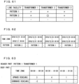
- FIG. 61 shows split information indicating the split result.
- the split information has a first row indicating a time zone of positive 30 minutes and a second row indicating a split pattern.
- FIG. 62 shows split pattern information indicating the split pattern.
- the split pattern information has a first row indicating a line facility, and a second row and subsequent rows in which the presence or absence of market split is indicated by ⁇ or x for each pattern. The presence and absence are indicated by ⁇ and x respectively.
- a pattern 2 is applied from 2018/12/31 23:30 to 2019/1/1 00:00, so that the split did not occur in the transformer 1 and in the transformer 3 while the split occurred in the transformer 2.
- the risk calculation unit 108 calculates a risk for each split pattern.
- a risk of the transformer 2 in a time zone from 00:00 to 00:30 will be described using the flow achievement information shown in FIG. 39 and the flow plan information shown in FIG. 40 as examples.
- flow achievements on 2018/12/29, 2018/12/30, and 2018/12/31 are 5 (kWh), 5 (kWh), and 8 (kWh) respectively.
- flow plans for 2018/12/29, 2018/12/30, and 2018/12/31 in the same time zone are 1 (kWh), 2 (kWh), and 3 (kWh) respectively.
- the risk calculation unit 108 calculates a risk of each line facility according to each of the patterns, and stores the calculated risk into the agreement condition storage unit 111.
- FIGS. 63 to 65 show risk information following each pattern stored in the agreement condition storage unit 111.
- FIGS. 63 , 64, and 65 show risk information following the pattern 1 about the transformer 1, about the transformer 2, and about the transformer 3 respectively.
- a header part of the risk information includes identification information about a line facility such as a line facility number and additionally, pattern information.
- Step S108 and step S109 after step S107A are the same as those of the second embodiment.
- the line constraint evaluation unit 110 makes a line constraint evaluation for the line facility individually (step S110A).
- the line constraint evaluation unit 110 makes a line constraint evaluation using a risk following the pattern 1 without split.
- the line constraint evaluation is made by the same method as that of the second embodiment.
- Steps from step S111 to step S113 after step S110A are the same as those of the second embodiment.
- the line constraint evaluation unit 110 makes a line constraint evaluation on the flow plan recalculated in step S113 (step S114A).
- the line constraint evaluation unit 110 makes the line constraint evaluation using a risk conforming to a current market split pattern. If split occurs only for the transformer 2, for example, the line constraint evaluation unit 110 adds a risk following the pattern 2 to the flow plan and then makes the line constraint evaluation.
- step S111 if the line constraint evaluation unit 110 determines that a flow plan to which the risk has been added does not deviate from the line constraint, the line constraint evaluation unit 110 stores a result about the current market split into the agreement condition storage unit (step S115).
- the risk calculation unit 108 calculates a risk for the line facility individually and for the market split pattern individually, and the line constraint evaluation unit 110 obtains a risk-considered flow plan by adding a risk corresponding to a market split pattern at the time of calculation of a flow plan to the flow plan. In this way, in the electric power agreement system 203, a risk is calculated for the market split pattern individually to achieve increase in the accuracy of risk calculation.
- the bidding information acquisition unit 101, the electric power generation achievement acquisition unit 102, the demand achievement acquisition unit 103, the line information acquisition unit 104, the surplus achievement calculation unit 105, the flow achievement calculation unit 106, the flow plan calculation unit 107, the risk calculation unit 108, the agreement result calculation unit 109, the line constraint evaluation unit 110, and the agreement condition storage unit 111 of the above-described electric power agreement system 201, 202, or 203 are realized by a processing circuit 81 shown in FIG. 66 .
- the processing circuit 81 includes the bidding information acquisition unit 101, the electric power generation achievement acquisition unit 102, the demand achievement acquisition unit 103, the line information acquisition unit 104, the surplus achievement calculation unit 105, the flow achievement calculation unit 106, the flow plan calculation unit 107, the risk calculation unit 108, the agreement result calculation unit 109, the line constraint evaluation unit 110, and the agreement condition storage unit 111 (these units will be called "units including the agreement result calculation unit 109").
- the processing circuit 81 may be dedicated hardware, or may be a processor to execute a program stored in a memory.
- the processor may be a central processing unit, a processing device, an arithmetic device, a microprocessor, a microcomputer, or a digital signal processor (DSP), for example.
- the processing circuit 81 corresponds to a single circuit, a complex circuit, a programmed processor, a parallel-programmed processor, an application specific integrated circuit (ASIC), a field-programmable gate array (FPGA), or a combination thereof, for example.
- the function of each unit such as the ... unit may be realized by a plurality of the processing circuits 81. Alternatively, the functions of all the units may be realized together in one processing circuit.
- the processing circuit 81 is a processor
- the functions of the units including the agreement result calculation unit 109 are realized by combination with software, etc. (software, firmware, or software and firmware).
- software is described as a program and stored into a memory.
- a processor 82 applied to the processing circuit 81 reads a program stored in a memory 83 and executes the read program, thereby realizing the function of each unit.
- the electric power agreement system 201, 202, or 203 includes the memory 83 for storing a program to be executed by the processing circuit 81 to result in implementations of: the step of calculating the agreement result 1006 including the amount of electric power to be traded and an electric power unit price about each of the customers; the step of calculating a total of actual numbers of the amount of surplus electric power about the customer connected to the line facility as a flow achievement for the line facility individually; the step of calculating a total value of the amounts of electric power to be traded in the agreement result 1006 about the customer connected to the line facility as a flow plan for the line facility individually; the step of calculating a variation of the flow achievement from the flow plan assumed in the future as a risk for the line facility individually on the basis of a variation of the flow achievement from the flow plan in the past; and the step of determining for the line facility individually whether a risk-considered flow plan obtained by adding the risk to the flow plan fulfills line constraint defined on the line facility.
- this program can be said to be
- the memory 83 can be a nonvolatile or volatile semiconductor memory such as a random access memory (RAM), a read only memory (ROM), a flash memory, an erasable programmable read only memory (EPROM) or an electrically erasable programmable read only memory (EEPROM), a hard disk drive (HDD), a magnetic disk, a flexible disk, an optical disk, a compact disk, a minidisk, a digital versatile disc (DVD), drivers thereof, or any type of storage medium assumed to be used in the future, for example.
- RAM random access memory
- ROM read only memory
- EPROM erasable programmable read only memory
- EEPROM electrically erasable programmable read only memory
- HDD hard disk drive
- magnetic disk a magnetic disk
- flexible disk an optical disk
- DVD digital versatile disc
- drivers thereof or any type of storage medium assumed to be used in the future, for example.
- the respective functions of the units including the agreement result calculation unit 109 are realized by one of hardware and software, etc.
- this is not the limited configuration.
- some of the units including the agreement result calculation unit 109 may be realized by dedicated hardware and a different one of the units may be realized by software, etc.
- the function of the agreement result calculation unit 109 may be realized by a processing circuit as dedicated hardware, and the functions of the other units may be realized by causing the processing circuit 81 as the processor 82 to read the program stored in the memory 83 and to execute the read program.
- the processing circuit is available for realizing each of the above-described functions using hardware, software, etc., or a combination thereof.
- the agreement condition storage unit 111 is composed of the memory 83, it can be composed of the memory 83 as a single memory or may composed of memories each functioning as an individual memory.
Landscapes
- Business, Economics & Management (AREA)
- Engineering & Computer Science (AREA)
- Economics (AREA)
- Strategic Management (AREA)
- Marketing (AREA)
- Human Resources & Organizations (AREA)
- Physics & Mathematics (AREA)
- General Business, Economics & Management (AREA)
- General Physics & Mathematics (AREA)
- Theoretical Computer Science (AREA)
- Development Economics (AREA)
- Finance (AREA)
- Accounting & Taxation (AREA)
- Health & Medical Sciences (AREA)
- Entrepreneurship & Innovation (AREA)
- Tourism & Hospitality (AREA)
- Water Supply & Treatment (AREA)
- Public Health (AREA)
- General Health & Medical Sciences (AREA)
- Primary Health Care (AREA)
- Game Theory and Decision Science (AREA)
- Power Engineering (AREA)
- Educational Administration (AREA)
- Operations Research (AREA)
- Quality & Reliability (AREA)
- Data Mining & Analysis (AREA)
- Technology Law (AREA)
- Management, Administration, Business Operations System, And Electronic Commerce (AREA)
- Supply And Distribution Of Alternating Current (AREA)
Abstract
Description
- The present invention relates to evaluation of the amount of electric power flowing through a line facility of an electric power line.
-
Patent Document 1 suggests an electric power transaction intermediation system by which, in calculating an agreement result from bidding information about trading of electric power, consideration is given to line constraint such as constraint on inter-regional interconnection to calculate an agreement result not deviating from the line constraint. - Patent Document 1:
Japanese Patent Application Laid-Open JP 2006 215 758 A - An electric power generation operator or a retail operator (these will be called an "operator" collectively) is obligated to pay a penalty if there is alienation between the amount of electric power actually generated or the amount of retail electric power sold and an agreement result, so that it has incentive to generate electric power or sell retail electric power in conformity with the agreement result. The electric power transaction intermediation system of
Patent Document 1 is based on the assumption that a player to trade electric power is an operator, so that no serious alienation occurs between the agreement result and electric power actually flowing through a line. - Regarding trading of electric power between electric power generators and electric power customers such as prosumers, however, these players are not obligated to pay the above-described penalty. Hence, in many cases, electric power actually flowing through a line does not conform to the agreement result. This causes a problem that, even if deviation from line constraint does not occur in terms of the agreement result, electric power actually flowing through the line deviates from the line constraint and this becomes a cause for breakdown of a line facility such as a transformer or a voltage inverter.
- The present invention has been made to solve the above-describe problem, and is intended to reduce the occurrence of breakdown of a line facility due to variation of electric power actually flowing through a line from an agreement result.
- An electric power agreement system according to the present invention is an electric power agreement system that evaluates a flow plan for an electric power line. The electric power line includes at least one line facility. At least one customer is connected to each line facility.
- The electric power agreement system includes: an agreement result calculation unit that calculates an agreement result including the amount of electric power to be traded and an electric power unit price about each customer; a flow achievement calculation unit that calculates a total of actual numbers of the amount of surplus electric power about the customer connected to the line facility as a flow achievement for the line facility individually; a flow plan calculation unit that calculates a total value of the amounts of electric power to be traded in the agreement result about the customer connected to the line facility as the flow plan for the line facility individually; a risk calculation unit that calculates a variation of the flow achievement from the flow plan assumed in the future as a risk for the line facility individually on the basis of a variation of the flow achievement from the flow plan in the past; and a line constraint evaluation unit that determines for the line facility individually whether a risk-considered flow plan obtained by adding the risk to the flow plan fulfills line constraint defined on the line facility.
- The electric power agreement system of the present invention is capable of evaluating the line constraint while giving consideration to the risk of variation of the flow achievement from the flow plan. Thus, by correcting the agreement result properly in response to a result of the evaluation, it becomes possible to reduce the occurrence of breakdown of the line facility due to variation of electric power actually flowing through the line from the agreement result. These and other objects, features, aspects and advantages of the present invention will become more apparent from the following detailed description and the accompanying drawings.
-
-
FIG. 1 is a configuration diagram of an electric power agreement system according to a first embodiment; -
FIG. 2 shows an electric power line to which the electric power agreement system according to the first embodiment is applied; -
FIG. 3 is a flowchart showing the operation of the electric power agreement system according to the first embodiment; -
FIG. 4 shows bidding information according to the first embodiment; -
FIG. 5 shows bidding information according to the first embodiment; -
FIG. 6 shows bidding information according to the first embodiment; -
FIG. 7 shows a relationship between a unit price and an amount in bidding information about purchase; -
FIG. 8 shows a relationship between a unit price and an amount in bidding information about sale; -
FIG. 9 shows electric power generation achievement information according to the first embodiment; -
FIG. 10 shows demand achievement information according to the first embodiment; -
FIG. 11 shows a line topology according to the first embodiment; -
FIG. 12 shows facility constraint information according to the first embodiment; -
FIG. 13 shows surplus achievement information according to the first embodiment; -
FIG. 14 shows flow achievement information according to the first embodiment; -
FIG. 15 shows flow plan information according to the first embodiment; -
FIG. 16 shows an evaluation index according to the first embodiment; -
FIG. 17 shows risk information about atransformer 1 according to the first embodiment; -
FIG. 18 shows risk information about atransformer 2 according to the first embodiment; -
FIG. 19 shows risk information about atransformer 3 according to the first embodiment; -
FIG. 20 shows agreement information about a customer 1-1 according to the first embodiment; -
FIG. 21 shows agreement information about a customer 2-1 according to the first embodiment; -
FIG. 22 shows agreement information about a customer 3-1 according to the first embodiment; -
FIG. 23 shows flow plan information about thetransformer 1 according to the first embodiment; -
FIG. 24 shows flow plan information about thetransformer 2 according to the first embodiment; -
FIG. 25 shows flow plan information about thetransformer 3 according to the first embodiment; -
FIG. 26 is a configuration diagram of an electric power agreement system according to a second embodiment; -
FIG. 27 shows an electric power line to which the electric power agreement system according to the second embodiment is applied; -
FIG. 28 is a flowchart showing the operation of the electric power agreement system according to the second embodiment; -
FIG. 29 shows bidding information according to the second embodiment; -
FIG. 30 shows bidding information according to the second embodiment; -
FIG. 31 shows bidding information according to the second embodiment; -
FIG. 32 shows bidding information according to the second embodiment; -
FIG. 33 shows electric power generation achievement information according to the second embodiment; -
FIG. 34 shows demand achievement information according to the second embodiment; -
FIG. 35 shows a line topology according to the second embodiment; -
FIG. 36 shows facility constraint information according to the second embodiment; -
FIG. 37 shows surplus achievement information about the customer 2-1 according to the second embodiment; -
FIG. 38 shows surplus achievement information about a customer 2-2 according to the second embodiment; -
FIG. 39 shows flow achievement information about thetransformer 2 according to the second embodiment; -
FIG. 40 shows flow plan information about thetransformer 2 according to the second embodiment; -
FIG. 41 shows an evaluation index according to the second embodiment; -
FIG. 42 shows risk information about thetransformer 1 according to the second embodiment; -
FIG. 43 shows risk information about thetransformer 2 according to the second embodiment; -
FIG. 44 shows risk information about thetransformer 3 according to the second embodiment; -
FIG. 45 shows agreement information about the customer 1-1 according to the second embodiment; -
FIG. 46 shows agreement information about the customer 2-1 according to the second embodiment; -
FIG. 47 shows agreement information about the customer 2-2 according to the second embodiment; -
FIG. 48 shows agreement information about the customer 3-1 according to the second embodiment; -
FIG. 49 shows flow plan information about thetransformer 1 according to the second embodiment; -
FIG. 50 shows flow plan information about thetransformer 2 according to the second embodiment; -
FIG. 51 shows flow plan information about thetransformer 3 according to the second embodiment; -
FIG. 52 shows recalculated agreement information about the customer 1-1 according to the second embodiment; -
FIG. 53 shows recalculated agreement information about the customer 2-1 according to the second embodiment; -
FIG. 54 shows recalculated agreement information about the customer 2-2 according to the second embodiment; -
FIG. 55 shows recalculated agreement information about the customer 3-1 according to the second embodiment; -
FIG. 56 shows recalculated flow plan information about thetransformer 1 according to the second embodiment; -
FIG. 57 shows recalculated flow plan information about thetransformer 2 according to the second embodiment; -
FIG. 58 shows recalculated flow plan information about thetransformer 3 according to the second embodiment; -
FIG. 59 is a configuration diagram of an electric power agreement system according to a third embodiment; -
FIG. 60 is a flowchart showing the operation of the electric power agreement system according to the third embodiment; -
FIG. 61 shows split information according to the third embodiment; -
FIG. 62 shows split pattern information according to the third embodiment; -
FIG. 63 shows risk information about thetransformer 1 following apattern 1 according to the third embodiment; -
FIG. 64 shows risk information about thetransformer 2 following thepattern 1 according to the third embodiment; -
FIG. 65 shows risk information about thetransformer 3 following thepattern 1 according to the third embodiment; -
FIG. 66 shows a hardware configuration of an electric power agreement system; and -
FIG. 67 shows a hardware configuration of an electric power agreement system. -
FIG. 1 is a configuration diagram of an electricpower agreement system 201 according to a first embodiment. The electricpower agreement system 201 is to make an agreement on trading of electric power with each customer of an electric power line and to determine whether a flow plan fulfills line constraint on the basis of anagreement result 1006. As shown inFIG. 1 , the electricpower agreement system 201 includes a biddinginformation acquisition unit 101, an electric power generationachievement acquisition unit 102, a demandachievement acquisition unit 103, a lineinformation acquisition unit 104, a surplusachievement calculation unit 105, a flowachievement calculation unit 106, a flowplan calculation unit 107, arisk calculation unit 108, an agreementresult calculation unit 109, and a lineconstraint evaluation unit 110. - The bidding
information acquisition unit 101 acquires biddinginformation 1001 from each customer. The electric power generationachievement acquisition unit 102 acquires electric powergeneration achievement information 1002 about each customer. The demandachievement acquisition unit 103 acquires a demand achievement of each customer. The lineinformation acquisition unit 104 acquiresline information 1004 about an electric power line. The surplusachievement calculation unit 105 calculates a surplus achievement of each customer. - The flow
achievement calculation unit 106 calculates a flow achievement of the line facility individually. The flowplan calculation unit 107 calculates a flow plan for the line facility individually. Therisk calculation unit 108 calculates an assumed variation of the flow achievement from the flow plan as a risk for the line facility individually. The agreementresult calculation unit 109 calculates theagreement result 1006 from bidding information about each customer according to a blind single price auction system. The lineconstraint evaluation unit 110 determines for the line facility individually whether the flow plan fulfills line constraint while giving consideration to the risk. -
FIG. 2 shows an electric power line to be evaluated in terms of line constraint by the electricpower agreement system 201. As shown inFIG. 2 , in the electric power line, threetransformers transformers - The electric
power agreement system 201 is owned and managed by a retail operator. Each customer has a retail contract with the retail operator. The electric power line inFIG. 2 is shown as an example. A line facility connected to the electric power line can be at least one, and a customer connected to one line facility can be at least one. - Each customer transmits bidding information to the electric
power agreement system 201 through a home energy management system (HEMS) owned by this customer, and the electricpower agreement system 201 performs agreement processing on the basis of the received bidding information. A PC or a smart meter may be responsible for transmission of the bidding information from each customer to the electricpower agreement system 201 instead of the HEMS, as long as it includes a communication unit, a storage unit, and a processor. - A transaction target of the agreement processing is the amount of electric power in positive 30 minutes. The positive 30 minutes mean a period from X o'clock to X thirty or from X thirty to (X + 1) o'clock. Here, X is an optional natural number. A market is to be opened by the start time of positive 30 minutes as a transaction target, and the electric
power agreement system 201 performs the agreement processing at the start time. Regarding a transaction of the amount of electric power from 2019/1/1 00:00 to 2019/1/1 00:30, for example, bedding is permitted until 2019/1/1 00:00 and the agreement processing is performed on 2019/1/1 00:00. The blind single price auction system is used for the agreement. -
FIG. 3 is a flowchart showing the operation of the electricpower agreement system 201. The operation of the electricpower agreement system 201 will be described on the basis of the flowchart inFIG. 3 while the amount of electric power from 2019/1/1 00:00 to 2019/1/1 00:30 is an example of a transaction target. The electricpower agreement system 201 calculates theagreement result 1006 on 2019/1/1 00:00, and determines the presence or absence of deviation from line constraint by giving consideration to the risk that the amount of electric power actually flowing through a line will deviate from theagreement result 1006. - First, the bidding
information acquisition unit 101 acquires thebidding information 1001 about each customer (step S101).FIGS. 4 to 6 show examples of thebidding information 1001. As shown inFIGS. 4 to 6 , thebidding information 1001 includes a header part and a body part. The header part of thebidding information 1001 includes identification information about a customer such as a customer number and an indication of sale or purchase. The indication of sale or purchase indicates whether bidding is for sale or for purchase. -
FIG. 4 shows thebidding information 1001 about sale about the customer 1-1.FIG. 5 shows thebidding information 1001 about purchase about the customer 2-1.FIG. 6 shows thebidding information 1001 about purchase about the customer 3-1. The body part of thebidding information 1001 has a first row indicating a unit price (¥/kWh) and a second row indicating the amount of electric power (kWh). -
FIG. 7 shows the body part of thebidding information 1001 about purchase in the form of a graph with a horizontal axis indicating a unit price and a vertical axis indicating an amount.FIG. 8 shows the body part of thebidding information 1001 about sale in the form of a graph prepared in the same way. As the single price auction system is used for agreement, the body part of thebidding information 1001 is generally drawn in a downward sloping graph in the case of purchase and is drawn in an upward sloping graph in the case of sale. - Next, the electric power generation
achievement acquisition unit 102 acquires the electric powergeneration achievement information 1002 indicating an electric power generation achievement of each customer (step S 102). The electric power generation achievement means an actual number of the amount of electric power actually generated by a customer.FIG. 9 shows an example of the electric powergeneration achievement information 1002 about the customer 2-1. - As shown in
FIG. 9 , the electric powergeneration achievement information 1002 includes a header part and a body part. The header part of the electric powergeneration achievement information 1002 includes a customer number. The body part of the electric powergeneration achievement information 1002 has a first row indicting a time zone of positive 30 minutes and a second row indicating the amount of electric power (kWh) corresponding to the electric power generation achievement. - Next, the demand
achievement acquisition unit 103 acquiresdemand achievement information 1003 indicating a demand achievement of each customer (step S103). The demand achievement means an actual number of the amount of electric power actually consumed by a customer.FIG. 10 shows an example of thedemand achievement information 1003 about the customer 2-1. As shown inFIG. 10 , thedemand achievement information 1003 includes a header part and a body part. The header part includes a customer number. The body part has a first row indicating a time zone of positive 30 minutes and a second row indicating the amount of electric power (kWh) corresponding to the demand achievement. - Next, the line
information acquisition unit 104 acquires the line information 1004 (step S104). Theline information 1004 is information about an electric power line to which the electricpower agreement system 201 is applied, and includes a line topology indicating the configuration of the electric power line and information about constraint on a line facility of the electric power line (this will be called "facility constraint information").FIG. 11 shows an example of the line topology. - The line topology in
FIG. 11 means that thetransformers transformer 1, the customer 2-1 is connected to thetransformer 2, and the customer 3-1 is connected to thetransformer 3.FIG. 12 shows an example of the facility constraint information. The facility constraint information has a first row indicating identification information about a line facility such as a line facility number and a second row indicating capacity constraint. The capacity constraint indicates an upper permissible value of the amount of electric power (including a reverse flow) to flow through the line facility. - Specifically, in the example shown in
FIG. 12 , the amount of electric power to flow through thetransformer 1 is constrained to be equal to or less than 22 (kWh), the amount of electric power to flow through thetransformer 2 is constrained to be equal to or less than 20 (kWh), and the amount of electric power to flow through thetransformer 3 is constrained to be equal to or less than 21 (kWh). - Next, the surplus
achievement calculation unit 105 calculates a surplus achievement (step S105). The surplus achievement means an actual number of the amount of electric power that becomes a surplus for a customer and is calculated by subtracting a demand achievement from an electric power generation achievement for each time zone.FIG. 13 shows an example of the surplus achievement information indicating the surplus achievement. As shown inFIG. 13 , the surplus achievement information includes a header part and a body part. The header part of the surplus achievement information includes a customer number. - The body part of the surplus achievement information has a first row indicating a time zone of positive 30 minutes and a second row indicating the amount of electric power (kWh) corresponding to the surplus achievement. Regarding the surplus achievement of the customer 2-1 in a time zone from 2018/12/31 23:30 to 2019/1/1 00:00, for example, as an electric power generation achievement in the same time zone is 10 (kWh) as shown in
FIG. 9 and a demand achievement in the same time zone is 7 (kWh) as shown inFIG. 10 , it is calculated as 10 - 7 = 3 (kWh). As the surplus achievement is determined by subtracting a demand achievement from an electric power generation achievement, a positive value of the surplus achievement means a reverse flow and a negative value thereof means a forward flow. - Next, the flow
achievement calculation unit 106 calculates a flow achievement of each line facility on the basis of theline information 1004 and a surplus achievement in the past (step S106). The flow achievement means an actual number of the amount of electric power having flowed through each line facility.FIG. 14 shows an example of the flow achievement information indicating the flow achievement. As shown inFIG. 14 , the flow achievement information includes a header part and a body part. - The header part of the flow achievement information indicates identification information about a line facility such as a line facility number. The body part of the flow achievement information has a first row indicating a time zone of positive 30 minutes and a second row indicating the amount of electric power (kWh) of the flow achievement. The flow
achievement calculation unit 106 determines a total value of surplus achievements of a customer connected to each line facility to be the flow achievement. - For example, the flow
achievement calculation unit 106 sees that the customer 2-1 is connected to thetransformer 2 on the basis of the line information, and acquires a surplus achievement of the customer 2-1 from the surplusachievement calculation unit 105. Then, the flowachievement calculation unit 106 determines this surplus achievement of the customer 2-1 to be the flow achievement of thetransformer 2. - Next, on the basis of a flow achievement in the past, a flow plan in the past, and an
evaluation index 1005, therisk calculation unit 108 calculates a variation of a flow achievement from a flow plan assumed in the future as a risk (step S107). The flow plan means the amount of electric power to flow through each line facility if surplus electric power of each consumer conforms to theagreement result 1006 and is calculated instep S 109 described later. -
FIG. 15 shows an example of flow plan information indicating the flow plan in the past. As shown inFIG. 15 , the flow plan information includes a header part and a body part. The header part of the flow plan information indicates identification information about a line facility such as a line facility number. The body part of the flow plan information has a first row indicating a time zone of positive 30 minutes and a second row indicating the amount of electric power (kWh) corresponding to the flow plan. - The
evaluation index 1005 is an index indicating to which extent a variation of a flow achievement from a flow plan in the past is to be calculated as a risk.FIG. 16 shows an example of theevaluation index 1005. In the example shown inFIG. 16 , theevaluation index 1005 shows "worst case in the past." Thus, therisk calculation unit 108 calculates a variation occurring in the worst case in the past, specifically, calculates a maximum of a variation of the flow achievement from the flow plan in the past as a risk. -
FIGS. 17 to 19 show examples of risk information indicating a risk. As shown inFIGS. 17 to 19 , the risk information includes a header part and a body part. The header part of the risk information indicates identification information about a line facility such as a line facility number. The body part of the risk information has a first row indicating a time zone of positive 30 minutes of any date, a second row indicating an upward risk, and a third row indicating a downward risk. - Here, the upward risk shows a maximum of a value (determined by subtracting a flow plan from a flow achievement) in the past in the time zone of the first row. Specifically, the upward risk shows a variation determined when the flow achievement varied most in the past toward a value exceeding the flow plan. However, if the flow achievement did not exceed the flow plan in the past, the upward risk is determined to be 0.
- The downward risk shows a maximum of a value (determined by subtracting a flow plan from a flow achievement) in the past in the time zone of the first row. Specifically, the downward risk shows a variation determined when the flow achievement varied most in the past toward a value falling under the flow plan. However, if the flow achievement did not fall under the flow plan in the past, the downward risk is determined to be 0.
- A risk of the
transformer 2 in a time zone from 00:00 to 00:30 will be described using the flow achievement information shown inFIG. 14 and the flow plan information shown inFIG. 15 as examples. With focus on the time zone from 00:00 to 00:30, as seen fromFIG. 14 , flow achievements on 2018/12/29, 2018/12/30, and 2018/12/31 are 6 (kWh), 5 (kWh), and -2 (kWh) respectively. As seen fromFIG. 15 , flow plans for 2018/12/29, 2018/12/30, and 2018/12/31 in the same time zone are 1 (kWh), 2 (kWh), and 3 (kWh) respectively. Accordingly, regarding the time zone from 00:00 to 00:30, an upward risk of thetransformer 2 is determined to be 5 (kWh) = max {6-1, 5-2, -2-3}, and a downward risk thereof is determined to be -5 (kWh) = min {6-1, 5-2, -2-3}. - The risk occurring in the situation where the
evaluation index 1005 is "worst case in the past" is as has been described above. Theevaluation index 1005 may alternatively be "possibility of equal to or greater than 90 %," for example. In this case, therisk calculation unit 108 calculates a variation as a risk that is to be determined if a flow achievement is assumed to vary from a flow plan with a probability of equal to or greater than 90 % based on data in the past. - More specifically, in a 90 % confidential interval of a probability distribution indicating a variation of a flow achievement from a flow plan in the past, the
risk calculation unit 108 determines a maximum and a minimum in this interval to be an upward risk and a downward risk respectively. Here, a confidential interval to be considered is not limited to the 90 % confidential interval but can be a confidential interval of any percentage. - Next, the agreement
result calculation unit 109 calculates theagreement result 1006 from thebidding information 1001 using the blind single price auction system (step S108).FIGS. 20 to 22 show examples of agreement information indicating theagreement result 1006. As shown inFIGS. 20 to 22 , the agreement information includes a header part and a body part. The header part of the agreement information indicates a customer number. -
FIG. 20 shows agreement information about the customer 1-1.FIG. 21 shows agreement information about the customer 2-1.FIG. 22 shows agreement information about the customer 3-1. The body part of the agreement information has a first row indicting a time zone of positive 30 minutes, a second row indicating an agreed amount of electric power (kWh), and a third row indicating an agreed price (¥/kWh). - Next, the flow
plan calculation unit 107 calculates a flow plan on the basis of theagreement result 1006 calculated in step S108 (step S109). The flow plan means a value of the amount of electric power intended to flow through each line facility and is a total value of agreed amounts of electric power for a customer connected to each line facility.FIGS. 23 to 25 show examples of flow plan information indicating the flow plan. As shown inFIGS. 23 to 25 , the flow plan information includes a header part and a body part. - The header part of the flow plan information indicates a line facility number. The body part of the flow plan information has a first row indicting a time zone of positive 30 minutes and a second row indicating the amount of electric power (kWh) corresponding to the flow plan.
FIG. 23 shows flow plan information about thetransformer 1.FIG. 24 shows flow plan information about thetransformer 2.FIG. 25 shows flow plan information about thetransformer 3. - The flow plan information in
FIG. 24 is prepared by adding a flow plan in a time zone from 2019/1/1 00:00 to 2019/1/1 00:30 next to the leftmost column of the body part of the flow plan information inFIG. 15 . The flowplan calculation unit 107 determines a total of agreed amounts of electric power for a customer connected to each line facility to be the flow plan. For example, the flowplan calculation unit 107 sees that the customer 2-1 is connected to thetransformer 2 on the basis of the line information, and acquires theagreement result 1006 about the customer 2-1 from the agreementresult calculation unit 109. Then, the flowplan calculation unit 107 determines an agreed amount of electric power for the customer 2-1 to be a flow plan for thetransformer 2. - Next, the line
constraint evaluation unit 110 determines whether the flow plan made for the plan facility individually by giving consideration to the risk fulfills line constraint, specifically, makes a line constraint evaluation (step S110). More specifically, the lineconstraint evaluation unit 110 adds the risk to the flow plan calculated in step S109, determines whether the flow plan to which the risk has been added (this will also be called a "risk-considered flow plan") fulfills the line constraint, and outputs a result of the evaluation. - By using the capacity constraint shown in
FIG. 12 as an example of the line constraint and using the flow plans shown inFIGS. 23 to 25 as examples, in an evaluation time zone (from 2019/1/1 00:00 to 2019/1/1 00:30), a flow plan for thetransformer 1 is 19 (kWh), a flow plan for thetransformer 2 is -18 (kWh), and a flow plan for thetransformer 3 is -1 (kWh). The capacity constraint on thetransformer 1 is 22 (kWh), the capacity constraint on thetransformer 2 is 20 (kWh), and the capacity constraint on thetransformer 3 is 21 (kWh). Thus, the flow plan without addition of the risk, namely, the flow plan without giving consideration to the risk fulfills the capacity constraint. - As shown in
FIG. 18 , however, the upward risk is 5 (kWh) and the downward risk is -5 (kWh) for thetransformer 2 in the evaluation time zone. Thus, a flow plan made by giving consideration to the upward risk is -18 + 5 = -13 (kWh) and a flow plan made by giving consideration to the downward risk is -18 -5 = -23 (kWh). Here, the flow plan -23 (kWh) made by giving consideration to the downward risk does not fulfill the capacity constraint of being equal to or less than 20 (kWh). - Regarding the
transformer 1, its flow plan made by giving consideration to the risk is still within a range from 18 (kWh) to 21 (kWh) to fulfill the capacity constraint of being equal to or less than 22 (kWh). Regarding thetransformer 3, its flow plan made by giving consideration to the risk is still within a range from -4 (kWh) to 3 (kWh) to fulfill the capacity constraint of being equal to or less than 21 (kWh). - The electric
power agreement system 201 of the first embodiment includes: the agreementresult calculation unit 109 that calculates theagreement result 1006 including the amount of electric power to be traded and an electric power unit price about each of the customers; the flowachievement calculation unit 106 that calculates a total of actual numbers of the amount of surplus electric power about the customer connected to the line facility as a flow achievement for the line facility individually; the flowplan calculation unit 107 that calculates a total value of the amounts of electric power to be traded in theagreement result 1006 about the customer connected to the line facility as a flow plan for the line facility individually; therisk calculation unit 108 that calculates a variation of the flow achievement from the flow plan assumed in the future as a risk for the line facility individually on the basis of a variation of the flow achievement from the flow plan in the past; and the lineconstraint evaluation unit 110 that determines for the line facility individually whether a risk-considered flow plan obtained by adding the risk to the flow plan fulfills line constraint defined on the line facility. Thus, the electricpower agreement system 201 is capable of determining whether the flow plan deviates from the line constraint while giving consideration to the risk of variation of the flow achievement from the flow plan. -
FIG. 26 is a configuration diagram of an electricpower agreement system 202 according to a second embodiment. The electricpower agreement system 202 is to make an agreement on trading of electric power with each customer of an electric power line and to determine whether a flow plan fulfills line constraint on the basis of theagreement result 1006. The electricpower agreement system 202 includes the same constituting elements as the electricpower agreement system 201 of the first embodiment. - However, the electric
power agreement system 202 differs from the electricpower agreement system 201 in that the agreementresult calculation unit 109 receives a result of evaluation by the line constraint evaluation unit, and if the flow plan does not fulfill the line constraint, splits a market in such a manner as to prevent deviation from the line constraint and recalculates theagreement result 1006. -
FIG. 27 shows an electric power line to be evaluated in terms of line constraint by the electricpower agreement system 202. As shown inFIG. 27 , in the electric power line, the threetransformers transformer 1, the customer 2-1 and a customer 2-2 are connected to thetransformer 2, and the customer 3-1 is connected to thetransformer 3. - The electric
power agreement system 202 makes an agreement by the blind single price auction system. According to the single price auction system, unless theagreement result 1006 calculated for every piece of bidding information deviates from line constraint, the same agreed price is applied to all customers. If theagreement result 1006 deviates from the line constraint, the electricpower agreement system 202 splits a market in such a manner as to prevent deviation from the line constraint and recalculates theagreement result 1006. - In this case, a group of bidding for purchase and bidding for sale differs between markets, so that the amount of bidding and a price for purchase and the amount of bidding and a price for sale to be matched with each other differ between the markets. As an example, if the customer 1-1, the customer 2-1, the customer 2-2, and the customer 3-1 submit bids, calculating the agreement results 1006 about all pieces of bidding information causes deviation from the line constraint.
- However, if deviation from the line constraint becomes avoidable by splitting the market into one for the customer 1-1 and the customer 3-1 and one for the customer 2-1 and the customer 2-2 and then calculating the agreement results 1006, the electric
power agreement system 202 calculates theagreement result 1006 for each of the split markets individually. In this case, a difference is generated between an agreed price for the customer 1-1 and the customer 3-1 and an agreed price for the customer 2-1 and the customer 2-2. -
FIG. 28 is a flowchart showing the operation of the electricpower agreement system 202. The operation of the electricpower agreement system 202 will be described on the basis of the flowchart inFIG. 28 while the amount of electric power from 2019/1/1 00:00 to 2019/1/1 00:30 is an example of a transaction target. The flow inFIG. 28 from step S101 to step S110 is the same as the flow inFIG. 3 described in the first embodiment. However, as the configuration of the electric power line is different from that of the first embodiment, explanation will be given again in line with the flow. - First, the bidding
information acquisition unit 101 acquires thebidding information 1001 about each customer (step S101).FIGS. 29 to 32 show examples of thebidding information 1001. The configuration of thebidding information 1001 is the same as that described in the first embodiment by referring toFIGS. 4 to 6 .FIG. 29 shows thebidding information 1001 about sale about the customer 1-1.FIG. 30 shows thebidding information 1001 about sale about the customer 2-1.FIG. 31 shows thebidding information 1001 about sale about the customer 2-2.FIG. 32 shows thebidding information 1001 about purchase about the customer 3-1. - Next, the electric power generation
achievement acquisition unit 102 acquires the electric powergeneration achievement information 1002 about each customer (step S102).FIG. 33 shows an example of the electric powergeneration achievement information 1002 about the customer 2-1. The configuration of the electric powergeneration achievement information 1002 is the same as that described in the first embodiment by referring toFIG. 9 . - Next, the demand
achievement acquisition unit 103 acquires thedemand achievement information 1003 about each customer (step S103).FIG. 34 shows an example of thedemand achievement information 1003 about the customer 2-1. The configuration of thedemand achievement information 1003 is the same as that described in the first embodiment by referring toFIG. 10 . - Next, the line
information acquisition unit 104 acquires the line information 1004 (step S104).FIG. 35 shows an example of a line topology included in theline information 1004. The line topology inFIG. 35 means that thetransformers transformer 1, the customer 2-1 and the customer 2-2 are connected to thetransformer 2, and the customer 3-1 is connected to thetransformer 3.FIG. 36 shows an example of facility constraint information included in theline information 1004. The configuration of the facility constraint information is the same as that described in the first embodiment by referring toFIG. 12 . - Next, the surplus
achievement calculation unit 105 calculates a surplus achievement (step S105).FIGS. 37 and 38 show examples of the surplus achievement information indicating the surplus achievement. The configuration of the surplus achievement information is the same as that described in the first embodiment by referring toFIG. 13 .FIG. 37 shows the surplus achievement information about the customer 2-1.FIG. 38 shows the surplus achievement information about the customer 2-2. - Next, the flow
achievement calculation unit 106 calculates a flow achievement of each line facility (step S106).FIG. 39 shows an example of the flow achievement information indicating the flow achievement. The configuration of the flow achievement information is the same as that described in the first embodiment by referring toFIG. 14 . For example, the flowachievement calculation unit 106 sees that the customer 2-1 and the customer 2-2 are connected to thetransformer 2 on the basis of the line information. - Then, the flow
achievement calculation unit 106 acquires a surplus achievement of the customer 2-1 and a surplus achievement of the customer 2-2 from the surplusachievement calculation unit 105. Next, the flowachievement calculation unit 106 determines a total of the surplus achievements of the customer 2-1 and the customer 2-2 to be the flow achievement of thetransformer 2. As an example, the flow achievement of thetransformer 2 in a time zone from 2018/12/31 23:30 to 2019/1/1 00:00 is 6 (kWh), which is a total of the surplus achievement 3 (kWh) of the customer 2-1 and the surplus achievement 3 (kWh) of the customer 2-2. - Next, on the basis of a flow achievement in the past, a flow plan in the past, and the
evaluation index 1005, therisk calculation unit 108 calculates a risk of a flow plan in the future (step S107).FIG. 40 shows an example of flow plan information indicating the flow plan in the past. The configuration of the flow plan information is the same as that described in the first embodiment by referring toFIG. 15 .FIG. 41 shows an example of theevaluation index 1005. In the example ofFIG. 41 , theevaluation index 1005 shows "worst case in the past." -
FIGS. 42 to 44 show examples of risk information indicating a risk. The configuration of the risk information is the same as that described in the first embodiment by referring toFIGS. 17 to 19 . A risk of thetransformer 2 in a time zone from 00:00 to 00:30 will be described using the flow achievement information shown inFIG. 39 and the flow plan information shown inFIG. 40 as examples. With focus on the time zone from 00:00 to 00:30, as seen fromFIG. 39 , flow achievements on 2018/12/29, 2018/12/30, and 2018/12/31 are 5 (kWh), 5 (kWh), and 8 (kWh) respectively. - As seen from
FIG. 40 , flow plans for 2018/12/29, 2018/12/30, and 2018/12/31 in the same time zone are 1 (kWh), 2 (kWh), and 3 (kWh) respectively. Accordingly, regarding the time zone from 00:00 to 00:30, an upward risk of thetransformer 2 is determined to be 5 (kWh) = max {5-1, 5-2, 8-3, 0}, and a downward risk thereof is determined to be 0 (kWh) = min {5-1, 5-2, 8-3, 0}. - Next, the agreement
result calculation unit 109 calculates theagreement result 1006 from the bidding information 1001 (step S108).FIGS. 45 to 48 show examples of agreement information indicating theagreement result 1006. The configuration of the agreement information is the same as that described in the first embodiment by referring toFIGS. 20 to 22 .FIG. 45 shows agreement information about the customer 1-1.FIG. 46 shows agreement information about the customer 2-1.FIG. 47 shows agreement information about the customer 2-2.FIG. 48 shows agreement information about the customer 3-1. As the agreement is made using the blind single price auction method, the same agreed price is applied for any customer in this step. - Next, the flow
plan calculation unit 107 calculates a flow plan on the basis of theagreement result 1006 calculated in step S108 (step S109).FIGS. 49 to 51 show examples of flow plan information indicating the flow plan. The configuration of the flow plan information is the same as that described in the first embodiment by referring toFIGS. 23 to 25 .FIG. 49 shows flow plan information about thetransformer 1.FIG. 50 shows flow plan information about thetransformer 2.FIG. 51 shows flow plan information about thetransformer 3. - The flow plan information in
FIG. 50 is prepared by adding a flow plan in a time zone from 2019/1/1 00:00 to 2019/1/1 00:30 next to the leftmost column of the body part of the flow plan information inFIG. 40 . The flowplan calculation unit 107 determines a total of agreed amounts of electric power for a customer connected to each line facility to be the flow plan. For example, the flowplan calculation unit 107 sees that the customer 2-1 and the customer 2-2 are connected to thetransformer 2 on the basis of the line information, and acquires theagreement result 1006 about each of the customer 2-1 and the customer 2-2 from the agreementresult calculation unit 109. Then, the flowplan calculation unit 107 determines a total of agreed amounts of electric power for the customer 2-1 and the customer 2-2 to be a flow plan for thetransformer 2. - Next, the line
constraint evaluation unit 110 determines whether the flow plan made for the plan facility individually by giving consideration to the risk fulfills line constraint, specifically, makes a line constraint evaluation (step S 110). - By using the capacity constraint shown in
FIG. 36 as an example of the line constraint and using the flow plans shown inFIGS. 49 to 51 as examples, in an evaluation time zone (from 2019/1/1 00:00 to 2019/1/1 00:30), a flow plan for thetransformer 1 is 19 (kWh), a flow plan for thetransformer 2 is -18 (kWh), and a flow plan for thetransformer 3 is -1 (kWh). The capacity constraint on thetransformer 1 is 22 (kWh), the capacity constraint on thetransformer 2 is 20 (kWh), and the capacity constraint on thetransformer 3 is 21 (kWh). Thus, the flow plan without addition of the risk, namely, the flow plan without giving consideration to the risk fulfills the capacity constraint. - As shown in
FIG. 43 , however, an upward risk is 5 (kWh) and a downward risk is -5 (kWh) for thetransformer 2 in the evaluation time zone. Thus, a flow plan made by giving consideration to the upward risk is -18 + 5 = -13 (kWh) and a flow plan made by giving consideration to the downward risk is -18 -2 = -23 (kWh). - Specifically, the flow plan for the
transformer 2 determined by giving consideration to the risks is in a range from -13 (kWh) to -23 (kWh) and does not fulfill the capacity constraint of being equal to or less than 20 (kWh). Regarding thetransformer 1, its flow plan made by giving consideration to the risk is still within a range from 18 (kWh) to 21 (kWh) to fulfill the capacity constraint of being equal to or less than 22 (kWh). Regarding thetransformer 3, its flow plan made by giving consideration to the risk is still within a range from -4 (kWh) to 3 (kWh) to fulfill the capacity constraint of being equal to or less than 21 (kWh). Thus, the lineconstraint evaluation unit 110 determines that the flow plan made by giving consideration to the risk does not fulfill the line constraint in thetransformer 2. - If the line constraint is fulfilled in every line facility (if Yes in step S111), the electric
power agreement system 202 finishes the processing. On the other hand, if the line constraint is not fulfilled in at least one line facility like in the above-described example (if No in step S111), the agreementresult calculation unit 109 recalculates the agreement result 1006 (step S112). In the above-described example, as the line constraint is not fulfilled in thetransformer 2, the agreementresult calculation unit 109 splits a market for thetransformer 2. Specifically, the agreementresult calculation unit 109 calculates the agreement results 1006 separately for the customers connected to thetransformer 2 and for the other customers. -
FIGS. 52 to 56 show examples of agreement information indicating theagreement result 1006 after the recalculation.FIG. 52 shows agreement information about the customer 1-1.FIG. 53 shows agreement information about the customer 2-1.FIG. 54 shows agreement information about the customer 2-2.FIG. 55 shows agreement information about the customer 3-1. - According to the examples of the agreement information shown in
FIGS. 52 to 55 , an agreed price is changed from 11 (kWh) to 10 (kWh) for the customer 1-1 and the customer 3-1, and an agreed price is changed from 11 (kWh) to 12 (kWh) for the customer 2-1 and the customer 2-2. In this way, the market is split between the customers connected to thetransformer 2 and the other customers to set the different agreed prices. - After step S112, the flow
plan calculation unit 107 recalculates a flow plan on the basis of theagreement result 1006 calculated in step S111 (step S113). On the basis of the agreement information shown in each ofFIGS. 52 to 55 , flow plan information shown in each ofFIGS. 56 to 58 is prepared. In comparison to the flow plan information previously prepared shown in each ofFIGS. 49 to 51 , flow plans for thetransformers - After step S113, the line
constraint evaluation unit 110 makes a line constraint evaluation on the flow plan recalculated in step S113 (step S114). More specifically, the lineconstraint evaluation unit 110 adds the risk to the flow plan calculated in step S113 and determines whether the flow plan to which the risk has been added fulfills the line constraint. - Process of the line constraint evaluation is the same as the process in step S110. In the examples of the flow plan information shown in
FIGS. 56 to 58 , as all the flow plans for thetransformers power agreement system 202 outputs the flow plans and theagreement result 1006 fulfilling the line constraint to the outside and finishes the processing. - In the electric
power agreement system 202 of the second embodiment, the agreementresult calculation unit 109 recalculates theagreement result 1006 about the customer connected to a deviating line facility by changing an electric power unit price until the lineconstraint evaluation unit 110 determines that the risk-considered flow plan for the deviating line facility fulfills the line constraint. The deviating line facility is the line facility for which the risk-considered flow plan is determined not to fulfill the line constraint by the lineconstraint evaluation unit 110. This allows the electricpower agreement system 202 to calculate theagreement result 1006 about the customer in such a manner as to fulfill the line constraint while giving consideration to the risk of variation of the flow achievement from the flow plan. - Furthermore, in the electric
power agreement system 202 of the second embodiment, the agreementresult calculation unit 109 splits a market for the deviating line facility from a market for the other line facility, and recalculates theagreement result 1006 about the customer by changing the electric power unit price for each of the split markets. This allows the electricpower agreement system 202 to calculate theagreement result 1006 about the customer in such a manner as to fulfill the line constraint while giving consideration to the risk of variation of the flow achievement from the flow plan. - In the second embodiment, even after recalculation of the
agreement result 1006, a line constraint evaluation is made on the basis of a constant risk. In an actual case, however, the risk might vary in response to the recalculation of theagreement result 1006. For example, if a market is split so corresponding reduction in sellers is caused, a customer to submit a bid for purchase for the same amount as an expected value of demand encounters reduction in agreeable bids compared to the absence of market split. This might cause serious alienation between a bid quantity and an agreed quantity. In response to this, in a third embodiment, a risk determined by giving consideration to an agreement condition such as market split is evaluated to increase the accuracy of risk evaluation. -
FIG. 59 is a configuration diagram of an electricpower agreement system 203 according to the third embodiment. The electricpower agreement system 203 includes an agreementcondition storage unit 111 in addition to the structures of the electricpower agreement system 202 according to the second embodiment. The agreementcondition storage unit 111 stores an agreement condition such as market split. Therisk calculation unit 108 calculates a risk by giving consideration to the agreement condition such as market split. -
FIG. 60 is a flowchart showing the operation of the electricpower agreement system 203. The operation of the electricpower agreement system 203 will be described on the basis of the flow inFIG. 60 . Steps from step S101 to stepS 106 inFIG. 60 are the same as those of the second embodiment. - After step S106, the
risk calculation unit 108 calculates a risk on the basis of a result about market split stored in the agreement condition storage unit 111 (step S107A).FIG. 61 shows split information indicating the split result. The split information has a first row indicating a time zone of positive 30 minutes and a second row indicating a split pattern.FIG. 62 shows split pattern information indicating the split pattern. The split pattern information has a first row indicating a line facility, and a second row and subsequent rows in which the presence or absence of market split is indicated by ∘ or x for each pattern. The presence and absence are indicated by ∘ and x respectively. As an example, apattern 2 is applied from 2018/12/31 23:30 to 2019/1/1 00:00, so that the split did not occur in thetransformer 1 and in thetransformer 3 while the split occurred in thetransformer 2. - The
risk calculation unit 108 calculates a risk for each split pattern. A risk of thetransformer 2 in a time zone from 00:00 to 00:30 will be described using the flow achievement information shown inFIG. 39 and the flow plan information shown inFIG. 40 as examples. With focus on the time zone from 00:00 to 00:30, as seen fromFIG. 39 , flow achievements on 2018/12/29, 2018/12/30, and 2018/12/31 are 5 (kWh), 5 (kWh), and 8 (kWh) respectively. As seen fromFIG. 40 , flow plans for 2018/12/29, 2018/12/30, and 2018/12/31 in the same time zone are 1 (kWh), 2 (kWh), and 3 (kWh) respectively. - Of the time zone from 00:00 to 00:30 on 2018/12/29, that on 2018/12/30, and that on 2018/12/31, only the time zones on the two days including 2018/12/31 and 2018/12/30 apply to a
pattern 1. Thus, an upward risk of thetransformer 2 in the time zone from 00:00 to 00:30 following thepattern 1 is determined to be 5 (kWh) = max {5-2, 8-3, 0}, and a downward risk thereof is determined to be 0 (kWh) = min {5-2, 8-3, 0}. - Of the time zone from 00:00 to 00:30 on 2018/12/29, that on 2018/12/30, and that on 2018/12/31, only the time zone on 2018/12/29 applies to the
pattern 2. Thus, an upward risk of thetransformer 2 in the time zone from 00:00 to 00:30 following thepattern 2 is determined to be 4 (kWh) = max {5-1, 0}, and a downward risk thereof is determined to be 0 (kWh) = min {5-1, 0}. In this way, therisk calculation unit 108 calculates a risk of each line facility according to each of the patterns, and stores the calculated risk into the agreementcondition storage unit 111. -
FIGS. 63 to 65 show risk information following each pattern stored in the agreementcondition storage unit 111.FIGS. 63 ,64, and 65 show risk information following thepattern 1 about thetransformer 1, about thetransformer 2, and about thetransformer 3 respectively. As shown inFIGS. 63 to 65 , a header part of the risk information includes identification information about a line facility such as a line facility number and additionally, pattern information. - Step S108 and step S109 after step S107A are the same as those of the second embodiment. After step S109, the line
constraint evaluation unit 110 makes a line constraint evaluation for the line facility individually (step S110A). As an evaluation in this step mentioned herein is to be made for the first time, the lineconstraint evaluation unit 110 makes a line constraint evaluation using a risk following thepattern 1 without split. The line constraint evaluation is made by the same method as that of the second embodiment. - Steps from step S111 to step S113 after step S110A are the same as those of the second embodiment. After step S113, the line
constraint evaluation unit 110 makes a line constraint evaluation on the flow plan recalculated in step S113 (step S114A). Here, the lineconstraint evaluation unit 110 makes the line constraint evaluation using a risk conforming to a current market split pattern. If split occurs only for thetransformer 2, for example, the lineconstraint evaluation unit 110 adds a risk following thepattern 2 to the flow plan and then makes the line constraint evaluation. - In step S111, if the line
constraint evaluation unit 110 determines that a flow plan to which the risk has been added does not deviate from the line constraint, the lineconstraint evaluation unit 110 stores a result about the current market split into the agreement condition storage unit (step S115). - In the electric
power agreement system 203 of the third embodiment, therisk calculation unit 108 calculates a risk for the line facility individually and for the market split pattern individually, and the lineconstraint evaluation unit 110 obtains a risk-considered flow plan by adding a risk corresponding to a market split pattern at the time of calculation of a flow plan to the flow plan. In this way, in the electricpower agreement system 203, a risk is calculated for the market split pattern individually to achieve increase in the accuracy of risk calculation. - The bidding
information acquisition unit 101, the electric power generationachievement acquisition unit 102, the demandachievement acquisition unit 103, the lineinformation acquisition unit 104, the surplusachievement calculation unit 105, the flowachievement calculation unit 106, the flowplan calculation unit 107, therisk calculation unit 108, the agreementresult calculation unit 109, the lineconstraint evaluation unit 110, and the agreementcondition storage unit 111 of the above-described electricpower agreement system processing circuit 81 shown inFIG. 66 . - Namely, the
processing circuit 81 includes the biddinginformation acquisition unit 101, the electric power generationachievement acquisition unit 102, the demandachievement acquisition unit 103, the lineinformation acquisition unit 104, the surplusachievement calculation unit 105, the flowachievement calculation unit 106, the flowplan calculation unit 107, therisk calculation unit 108, the agreementresult calculation unit 109, the lineconstraint evaluation unit 110, and the agreement condition storage unit 111 (these units will be called "units including the agreementresult calculation unit 109"). Theprocessing circuit 81 may be dedicated hardware, or may be a processor to execute a program stored in a memory. The processor may be a central processing unit, a processing device, an arithmetic device, a microprocessor, a microcomputer, or a digital signal processor (DSP), for example. - If the
processing circuit 81 is dedicated hardware, theprocessing circuit 81 corresponds to a single circuit, a complex circuit, a programmed processor, a parallel-programmed processor, an application specific integrated circuit (ASIC), a field-programmable gate array (FPGA), or a combination thereof, for example. The function of each unit such as the ... unit may be realized by a plurality of theprocessing circuits 81. Alternatively, the functions of all the units may be realized together in one processing circuit. - If the
processing circuit 81 is a processor, the functions of the units including the agreementresult calculation unit 109 are realized by combination with software, etc. (software, firmware, or software and firmware). Such software is described as a program and stored into a memory. As shown inFIG. 67 , aprocessor 82 applied to theprocessing circuit 81 reads a program stored in amemory 83 and executes the read program, thereby realizing the function of each unit. - Specifically, the electric
power agreement system memory 83 for storing a program to be executed by theprocessing circuit 81 to result in implementations of: the step of calculating theagreement result 1006 including the amount of electric power to be traded and an electric power unit price about each of the customers; the step of calculating a total of actual numbers of the amount of surplus electric power about the customer connected to the line facility as a flow achievement for the line facility individually; the step of calculating a total value of the amounts of electric power to be traded in theagreement result 1006 about the customer connected to the line facility as a flow plan for the line facility individually; the step of calculating a variation of the flow achievement from the flow plan assumed in the future as a risk for the line facility individually on the basis of a variation of the flow achievement from the flow plan in the past; and the step of determining for the line facility individually whether a risk-considered flow plan obtained by adding the risk to the flow plan fulfills line constraint defined on the line facility. In other words, this program can be said to be a program for causing a computer to execute procedures or methods of the units including the agreementresult calculation unit 109. - Here, the
memory 83 can be a nonvolatile or volatile semiconductor memory such as a random access memory (RAM), a read only memory (ROM), a flash memory, an erasable programmable read only memory (EPROM) or an electrically erasable programmable read only memory (EEPROM), a hard disk drive (HDD), a magnetic disk, a flexible disk, an optical disk, a compact disk, a minidisk, a digital versatile disc (DVD), drivers thereof, or any type of storage medium assumed to be used in the future, for example. - In the foregoing configuration, the respective functions of the units including the agreement
result calculation unit 109 are realized by one of hardware and software, etc. However, this is not the limited configuration. In one configuration, some of the units including the agreementresult calculation unit 109 may be realized by dedicated hardware and a different one of the units may be realized by software, etc. For example, the function of the agreementresult calculation unit 109 may be realized by a processing circuit as dedicated hardware, and the functions of the other units may be realized by causing theprocessing circuit 81 as theprocessor 82 to read the program stored in thememory 83 and to execute the read program. - As described above, the processing circuit is available for realizing each of the above-described functions using hardware, software, etc., or a combination thereof. While the agreement
condition storage unit 111 is composed of thememory 83, it can be composed of thememory 83 as a single memory or may composed of memories each functioning as an individual memory. - The embodiments can be combined freely or each of the embodiments can be modified or omitted, if appropriate. The foregoing description is in all aspects illustrative. It is therefore understood that numerous modifications not shown can be devised.
-
- 101
- Bidding information acquisition unit
- 102
- Electric power generation achievement acquisition unit
- 103
- Demand achievement acquisition unit
- 104
- Line information acquisition unit
- 105
- Surplus achievement calculation unit
- 106
- Flow achievement calculation unit
- 107
- Flow plan calculation unit
- 108
- Risk calculation unit
- 109
- Agreement result calculation unit
- 110
- Line constraint evaluation unit
- 111
- Agreement condition storage unit
- 201 to 203
- Electric power agreement system
Claims (7)
- An electric power agreement system that evaluates a flow plan for an electric power line,the electric power line including at least one line facility,at least one customer being connected to each of the line facilities,the electric power agreement system comprising:an agreement result calculation unit that calculates an agreement result including the amount of electric power to be traded and an electric power unit price about each of the customers;a flow achievement calculation unit that calculates a total of actual numbers of the amount of surplus electric power about the customer connected to the line facility as a flow achievement for the line facility individually;a flow plan calculation unit that calculates a total value of the amounts of electric power to be traded in the agreement result about the customer connected to the line facility as the flow plan for the line facility individually;a risk calculation unit that calculates a variation of the flow achievement from the flow plan assumed in the future as a risk for the line facility individually on the basis of a variation of the flow achievement from the flow plan in the past;
anda line constraint evaluation unit that determines for the line facility individually whether a risk-considered flow plan obtained by adding the risk to the flow plan fulfills line constraint defined on the line facility. - The electric power agreement system according to claim 1,
wherein the risk calculation unit calculates a maximum of a variation of the flow achievement from the flow plan in the past as the risk. - The electric power agreement system according to claim 1,
wherein the risk calculation unit calculates a boundary value in a confidential interval of a probability distribution of a variation of the flow achievement from the flow plan in the past as the risk. - The electric power agreement system according to any one of claims 1 to 3, wherein the agreement result calculation unit recalculates the agreement result about the customer connected to a deviating line facility by changing the electric power unit price until the line constraint evaluation unit determines that the risk-considered flow plan for the deviating line facility fulfills the line constraint, the deviating line facility being the line facility for which the risk-considered flow plan is determined not to fulfill the line constraint by the line constraint evaluation unit.
- The electric power agreement system according to claim 4,
wherein the agreement result calculation unit splits a market for the deviating line facility from a market for the other line facility, and recalculates the agreement result about the customer by changing the electric power unit price for each of the split markets. - The electric power agreement system according to claim 4,wherein the risk calculation unit calculates the risk for the line facility individually and for a market split pattern individually, andthe line constraint evaluation unit obtains the risk-considered flow plan by adding the risk corresponding to the market split pattern at the time of calculation of the flow plan to the flow plan.
- An electric power agreement method of evaluating a flow plan for an electric power line,the electric power line including at least one line facility,at least one customer being connected to each of the line facilities,the electric power agreement method comprising:calculating an agreement result including the amount of electric power to be traded and an electric power unit price about each of the customers;calculating a total of actual numbers of the amount of surplus electric power about the customer connected to the line facility as a flow achievement for the line facility individually;calculating a total value of the amounts of electric power to be traded in the agreement result about the customer connected to the line facility as the flow plan for the line facility individually;calculating a variation of the flow achievement from the flow plan assumed in the future as a risk for the line facility individually on the basis of a variation of the flow achievement from the flow plan in the past; anddetermining for the line facility individually whether a risk-considered flow plan obtained by adding the risk to the flow plan fulfills line constraint defined on the line facility.
Applications Claiming Priority (1)
| Application Number | Priority Date | Filing Date | Title |
|---|---|---|---|
| PCT/JP2020/018059 WO2021220381A1 (en) | 2020-04-28 | 2020-04-28 | Electric power contract system and electric power contract method |
Publications (2)
| Publication Number | Publication Date |
|---|---|
| EP4145376A1 true EP4145376A1 (en) | 2023-03-08 |
| EP4145376A4 EP4145376A4 (en) | 2023-06-21 |
Family
ID=78373441
Family Applications (1)
| Application Number | Title | Priority Date | Filing Date |
|---|---|---|---|
| EP20932873.1A Withdrawn EP4145376A4 (en) | 2020-04-28 | 2020-04-28 | ELECTRIC POWER CONTRACT SYSTEM AND ELECTRIC POWER CONTRACT METHOD |
Country Status (5)
| Country | Link |
|---|---|
| US (1) | US12282972B2 (en) |
| EP (1) | EP4145376A4 (en) |
| JP (1) | JP7286012B2 (en) |
| CN (1) | CN115428005A (en) |
| WO (1) | WO2021220381A1 (en) |
Family Cites Families (10)
| Publication number | Priority date | Publication date | Assignee | Title |
|---|---|---|---|---|
| US7430534B2 (en) * | 2001-06-15 | 2008-09-30 | Abb Ab | System, method and computer program product for risk-minimization and mutual insurance relations in meteorology dependent activities |
| US20040215545A1 (en) * | 2003-01-31 | 2004-10-28 | Kabushiki Kaisha Toshiba | Power trading risk management system |
| JP4329644B2 (en) * | 2004-08-16 | 2009-09-09 | 株式会社日立製作所 | Market analyzer |
| JP2006215758A (en) | 2005-02-02 | 2006-08-17 | Hitachi Ltd | Power transaction mediation system, power transaction mediation method, and power transaction mediation program |
| JP4607632B2 (en) | 2005-03-16 | 2011-01-05 | 株式会社東芝 | Power transaction evaluation support system, method, and program |
| JP6936117B2 (en) | 2017-11-10 | 2021-09-15 | 株式会社日立製作所 | Power planning equipment, power supply and demand control system, and power planning method |
| US10430898B2 (en) * | 2017-12-06 | 2019-10-01 | NAD Grid Corp | Method and system for facilitating electricity services |
| JP7012580B2 (en) * | 2018-03-30 | 2022-01-28 | 株式会社日立製作所 | Management equipment, management method and management system |
| EP3914992A4 (en) * | 2019-01-22 | 2023-03-08 | Dmk Nano Llc | ENERGY DISTRIBUTION MANAGEMENT BASED ON DISTRIBUTED NETWORKING PROTOCOL ANALYZES |
| US11705755B2 (en) * | 2020-02-28 | 2023-07-18 | Alliance For Sustainable Energy, Llc | Power system restoration incorporating diverse distributed energy resources |
-
2020
- 2020-04-28 WO PCT/JP2020/018059 patent/WO2021220381A1/en not_active Ceased
- 2020-04-28 EP EP20932873.1A patent/EP4145376A4/en not_active Withdrawn
- 2020-04-28 JP JP2022518470A patent/JP7286012B2/en active Active
- 2020-04-28 US US17/798,568 patent/US12282972B2/en active Active
- 2020-04-28 CN CN202080100056.8A patent/CN115428005A/en active Pending
Also Published As
| Publication number | Publication date |
|---|---|
| WO2021220381A1 (en) | 2021-11-04 |
| US12282972B2 (en) | 2025-04-22 |
| JP7286012B2 (en) | 2023-06-02 |
| JPWO2021220381A1 (en) | 2021-11-04 |
| CN115428005A (en) | 2022-12-02 |
| US20230065402A1 (en) | 2023-03-02 |
| EP4145376A4 (en) | 2023-06-21 |
Similar Documents
| Publication | Publication Date | Title |
|---|---|---|
| US20190130423A1 (en) | Management apparatus and management method | |
| Pineda et al. | Using electricity options to hedge against financial risks of power producers | |
| US10796254B2 (en) | Systems, methods and apparatus for integrated optimal outage coordination in energy delivery systems | |
| Algarvio et al. | Agent-based retail competition and portfolio optimization in liberalized electricity markets: A study involving real-world consumers | |
| Rudnick et al. | Learning from developing country power market experiences: the case of the Philippines | |
| Tesfatsion | A new swing-contract design for wholesale power markets | |
| JP7525294B2 (en) | Power sales planning device, power sales planning method, and power sales planning program | |
| Woo et al. | A nice electricity market design | |
| JP2018173678A (en) | Support device, support system, support method, and program | |
| Cervigni et al. | Wholesale electricity markets | |
| EP4145376A1 (en) | Electric power contract system and electric power contract method | |
| Zachmann et al. | The design of the European electricity market | |
| CN111160787A (en) | Transaction strategy determination method and device, readable medium and electronic equipment | |
| Zhou et al. | Comparison of Market Designs | |
| Singh et al. | Wind power trading options in competitive electricity market | |
| Ciarreta et al. | Supply function competition in the Spanish wholesale electricity market | |
| JP7013348B2 (en) | Surplus electricity trading equipment and programs | |
| Forouli et al. | AC-feasible Local Flexibility Market with Continuous Trading | |
| US11973346B2 (en) | Transactive energy system and method | |
| Kahn et al. | Auctions for PURPA purchases: A simulation study | |
| Bierling et al. | Review of multi-BRP, aggregator settlement models at large-scale connections in the European electricity system | |
| Peña Sánchez et al. | The energy policy pricing dilemma: Affordability, volatility, and market signals in electricity tariffs | |
| Bell et al. | Project TransmiT: Academic review of transmission charging arrangements | |
| JP2026006728A (en) | Information processing device, information processing method, and program | |
| JP2026028276A (en) | Information processing device, information processing method, and program |
Legal Events
| Date | Code | Title | Description |
|---|---|---|---|
| STAA | Information on the status of an ep patent application or granted ep patent |
Free format text: STATUS: THE INTERNATIONAL PUBLICATION HAS BEEN MADE |
|
| PUAI | Public reference made under article 153(3) epc to a published international application that has entered the european phase |
Free format text: ORIGINAL CODE: 0009012 |
|
| STAA | Information on the status of an ep patent application or granted ep patent |
Free format text: STATUS: REQUEST FOR EXAMINATION WAS MADE |
|
| 17P | Request for examination filed |
Effective date: 20221014 |
|
| AK | Designated contracting states |
Kind code of ref document: A1 Designated state(s): AL AT BE BG CH CY CZ DE DK EE ES FI FR GB GR HR HU IE IS IT LI LT LU LV MC MK MT NL NO PL PT RO RS SE SI SK SM TR |
|
| A4 | Supplementary search report drawn up and despatched |
Effective date: 20230522 |
|
| RIC1 | Information provided on ipc code assigned before grant |
Ipc: G06Q 10/063 20230101ALI20230515BHEP Ipc: G06Q 30/0201 20230101ALI20230515BHEP Ipc: G06Q 40/04 20120101ALI20230515BHEP Ipc: H02J 3/00 20060101ALI20230515BHEP Ipc: G06Q 50/06 20120101AFI20230515BHEP |
|
| DAV | Request for validation of the european patent (deleted) | ||
| DAX | Request for extension of the european patent (deleted) | ||
| STAA | Information on the status of an ep patent application or granted ep patent |
Free format text: STATUS: EXAMINATION IS IN PROGRESS |
|
| 17Q | First examination report despatched |
Effective date: 20240513 |
|
| STAA | Information on the status of an ep patent application or granted ep patent |
Free format text: STATUS: THE APPLICATION HAS BEEN WITHDRAWN |
|
| 18W | Application withdrawn |
Effective date: 20251007 |