EP4145339A1 - Vehicle drivable area detection method, system, and automatic driving vehicle using system - Google Patents
Vehicle drivable area detection method, system, and automatic driving vehicle using system Download PDFInfo
- Publication number
- EP4145339A1 EP4145339A1 EP20935061.0A EP20935061A EP4145339A1 EP 4145339 A1 EP4145339 A1 EP 4145339A1 EP 20935061 A EP20935061 A EP 20935061A EP 4145339 A1 EP4145339 A1 EP 4145339A1
- Authority
- EP
- European Patent Office
- Prior art keywords
- obstacle
- vehicle
- probability
- radar
- probability distribution
- Prior art date
- Legal status (The legal status is an assumption and is not a legal conclusion. Google has not performed a legal analysis and makes no representation as to the accuracy of the status listed.)
- Pending
Links
- 238000001514 detection method Methods 0.000 title claims abstract description 18
- 238000000034 method Methods 0.000 claims abstract description 69
- 238000009826 distribution Methods 0.000 claims abstract description 65
- 238000013528 artificial neural network Methods 0.000 claims abstract description 63
- 238000012545 processing Methods 0.000 claims abstract description 22
- 230000004927 fusion Effects 0.000 claims abstract description 18
- 230000008569 process Effects 0.000 claims description 30
- 230000011218 segmentation Effects 0.000 claims description 20
- 238000012549 training Methods 0.000 claims description 19
- 238000013507 mapping Methods 0.000 claims description 11
- 238000011176 pooling Methods 0.000 claims description 4
- 230000009467 reduction Effects 0.000 claims description 4
- 230000003247 decreasing effect Effects 0.000 claims description 3
- 230000006870 function Effects 0.000 description 27
- 238000010586 diagram Methods 0.000 description 15
- 238000004891 communication Methods 0.000 description 8
- 238000005516 engineering process Methods 0.000 description 7
- 238000004364 calculation method Methods 0.000 description 4
- 230000003068 static effect Effects 0.000 description 4
- 102100034112 Alkyldihydroxyacetonephosphate synthase, peroxisomal Human genes 0.000 description 3
- 101000799143 Homo sapiens Alkyldihydroxyacetonephosphate synthase, peroxisomal Proteins 0.000 description 3
- 101100370014 Neurospora crassa (strain ATCC 24698 / 74-OR23-1A / CBS 708.71 / DSM 1257 / FGSC 987) tof-1 gene Proteins 0.000 description 3
- 238000000848 angular dependent Auger electron spectroscopy Methods 0.000 description 3
- 230000008878 coupling Effects 0.000 description 3
- 238000010168 coupling process Methods 0.000 description 3
- 238000005859 coupling reaction Methods 0.000 description 3
- 238000002156 mixing Methods 0.000 description 3
- 230000008901 benefit Effects 0.000 description 2
- 230000000694 effects Effects 0.000 description 2
- 238000003062 neural network model Methods 0.000 description 2
- 230000000007 visual effect Effects 0.000 description 2
- 230000006399 behavior Effects 0.000 description 1
- 230000005540 biological transmission Effects 0.000 description 1
- 238000012512 characterization method Methods 0.000 description 1
- 238000006243 chemical reaction Methods 0.000 description 1
- 238000004590 computer program Methods 0.000 description 1
- 238000012937 correction Methods 0.000 description 1
- 238000013434 data augmentation Methods 0.000 description 1
- 238000013480 data collection Methods 0.000 description 1
- 230000007423 decrease Effects 0.000 description 1
- 238000011161 development Methods 0.000 description 1
- 230000018109 developmental process Effects 0.000 description 1
- 238000002592 echocardiography Methods 0.000 description 1
- 238000007499 fusion processing Methods 0.000 description 1
- 238000003384 imaging method Methods 0.000 description 1
- 238000010801 machine learning Methods 0.000 description 1
- 238000005259 measurement Methods 0.000 description 1
- 238000012986 modification Methods 0.000 description 1
- 230000004048 modification Effects 0.000 description 1
- 238000012544 monitoring process Methods 0.000 description 1
- 230000003287 optical effect Effects 0.000 description 1
- 230000008447 perception Effects 0.000 description 1
- 238000011160 research Methods 0.000 description 1
- 230000000717 retained effect Effects 0.000 description 1
- 230000035945 sensitivity Effects 0.000 description 1
- 238000012546 transfer Methods 0.000 description 1
- 230000009466 transformation Effects 0.000 description 1
Images


Classifications
-
- G—PHYSICS
- G06—COMPUTING; CALCULATING OR COUNTING
- G06V—IMAGE OR VIDEO RECOGNITION OR UNDERSTANDING
- G06V20/00—Scenes; Scene-specific elements
- G06V20/50—Context or environment of the image
- G06V20/56—Context or environment of the image exterior to a vehicle by using sensors mounted on the vehicle
- G06V20/58—Recognition of moving objects or obstacles, e.g. vehicles or pedestrians; Recognition of traffic objects, e.g. traffic signs, traffic lights or roads
-
- G—PHYSICS
- G06—COMPUTING; CALCULATING OR COUNTING
- G06F—ELECTRIC DIGITAL DATA PROCESSING
- G06F18/00—Pattern recognition
- G06F18/20—Analysing
- G06F18/25—Fusion techniques
- G06F18/254—Fusion techniques of classification results, e.g. of results related to same input data
- G06F18/256—Fusion techniques of classification results, e.g. of results related to same input data of results relating to different input data, e.g. multimodal recognition
-
- B—PERFORMING OPERATIONS; TRANSPORTING
- B60—VEHICLES IN GENERAL
- B60W—CONJOINT CONTROL OF VEHICLE SUB-UNITS OF DIFFERENT TYPE OR DIFFERENT FUNCTION; CONTROL SYSTEMS SPECIALLY ADAPTED FOR HYBRID VEHICLES; ROAD VEHICLE DRIVE CONTROL SYSTEMS FOR PURPOSES NOT RELATED TO THE CONTROL OF A PARTICULAR SUB-UNIT
- B60W60/00—Drive control systems specially adapted for autonomous road vehicles
- B60W60/001—Planning or execution of driving tasks
-
- G—PHYSICS
- G01—MEASURING; TESTING
- G01C—MEASURING DISTANCES, LEVELS OR BEARINGS; SURVEYING; NAVIGATION; GYROSCOPIC INSTRUMENTS; PHOTOGRAMMETRY OR VIDEOGRAMMETRY
- G01C21/00—Navigation; Navigational instruments not provided for in groups G01C1/00 - G01C19/00
- G01C21/26—Navigation; Navigational instruments not provided for in groups G01C1/00 - G01C19/00 specially adapted for navigation in a road network
- G01C21/28—Navigation; Navigational instruments not provided for in groups G01C1/00 - G01C19/00 specially adapted for navigation in a road network with correlation of data from several navigational instruments
- G01C21/30—Map- or contour-matching
- G01C21/32—Structuring or formatting of map data
-
- G—PHYSICS
- G01—MEASURING; TESTING
- G01C—MEASURING DISTANCES, LEVELS OR BEARINGS; SURVEYING; NAVIGATION; GYROSCOPIC INSTRUMENTS; PHOTOGRAMMETRY OR VIDEOGRAMMETRY
- G01C21/00—Navigation; Navigational instruments not provided for in groups G01C1/00 - G01C19/00
- G01C21/26—Navigation; Navigational instruments not provided for in groups G01C1/00 - G01C19/00 specially adapted for navigation in a road network
- G01C21/34—Route searching; Route guidance
- G01C21/3407—Route searching; Route guidance specially adapted for specific applications
- G01C21/343—Calculating itineraries, i.e. routes leading from a starting point to a series of categorical destinations using a global route restraint, round trips, touristic trips
-
- G—PHYSICS
- G01—MEASURING; TESTING
- G01C—MEASURING DISTANCES, LEVELS OR BEARINGS; SURVEYING; NAVIGATION; GYROSCOPIC INSTRUMENTS; PHOTOGRAMMETRY OR VIDEOGRAMMETRY
- G01C21/00—Navigation; Navigational instruments not provided for in groups G01C1/00 - G01C19/00
- G01C21/26—Navigation; Navigational instruments not provided for in groups G01C1/00 - G01C19/00 specially adapted for navigation in a road network
- G01C21/34—Route searching; Route guidance
- G01C21/3453—Special cost functions, i.e. other than distance or default speed limit of road segments
- G01C21/3461—Preferred or disfavoured areas, e.g. dangerous zones, toll or emission zones, intersections, manoeuvre types, segments such as motorways, toll roads, ferries
-
- G—PHYSICS
- G01—MEASURING; TESTING
- G01C—MEASURING DISTANCES, LEVELS OR BEARINGS; SURVEYING; NAVIGATION; GYROSCOPIC INSTRUMENTS; PHOTOGRAMMETRY OR VIDEOGRAMMETRY
- G01C21/00—Navigation; Navigational instruments not provided for in groups G01C1/00 - G01C19/00
- G01C21/38—Electronic maps specially adapted for navigation; Updating thereof
- G01C21/3804—Creation or updating of map data
- G01C21/3807—Creation or updating of map data characterised by the type of data
- G01C21/3815—Road data
-
- G—PHYSICS
- G01—MEASURING; TESTING
- G01S—RADIO DIRECTION-FINDING; RADIO NAVIGATION; DETERMINING DISTANCE OR VELOCITY BY USE OF RADIO WAVES; LOCATING OR PRESENCE-DETECTING BY USE OF THE REFLECTION OR RERADIATION OF RADIO WAVES; ANALOGOUS ARRANGEMENTS USING OTHER WAVES
- G01S13/00—Systems using the reflection or reradiation of radio waves, e.g. radar systems; Analogous systems using reflection or reradiation of waves whose nature or wavelength is irrelevant or unspecified
- G01S13/88—Radar or analogous systems specially adapted for specific applications
- G01S13/89—Radar or analogous systems specially adapted for specific applications for mapping or imaging
-
- G—PHYSICS
- G01—MEASURING; TESTING
- G01S—RADIO DIRECTION-FINDING; RADIO NAVIGATION; DETERMINING DISTANCE OR VELOCITY BY USE OF RADIO WAVES; LOCATING OR PRESENCE-DETECTING BY USE OF THE REFLECTION OR RERADIATION OF RADIO WAVES; ANALOGOUS ARRANGEMENTS USING OTHER WAVES
- G01S13/00—Systems using the reflection or reradiation of radio waves, e.g. radar systems; Analogous systems using reflection or reradiation of waves whose nature or wavelength is irrelevant or unspecified
- G01S13/88—Radar or analogous systems specially adapted for specific applications
- G01S13/93—Radar or analogous systems specially adapted for specific applications for anti-collision purposes
- G01S13/931—Radar or analogous systems specially adapted for specific applications for anti-collision purposes of land vehicles
-
- G—PHYSICS
- G06—COMPUTING; CALCULATING OR COUNTING
- G06F—ELECTRIC DIGITAL DATA PROCESSING
- G06F16/00—Information retrieval; Database structures therefor; File system structures therefor
- G06F16/20—Information retrieval; Database structures therefor; File system structures therefor of structured data, e.g. relational data
- G06F16/29—Geographical information databases
-
- G—PHYSICS
- G06—COMPUTING; CALCULATING OR COUNTING
- G06F—ELECTRIC DIGITAL DATA PROCESSING
- G06F16/00—Information retrieval; Database structures therefor; File system structures therefor
- G06F16/50—Information retrieval; Database structures therefor; File system structures therefor of still image data
- G06F16/58—Retrieval characterised by using metadata, e.g. metadata not derived from the content or metadata generated manually
- G06F16/583—Retrieval characterised by using metadata, e.g. metadata not derived from the content or metadata generated manually using metadata automatically derived from the content
- G06F16/5854—Retrieval characterised by using metadata, e.g. metadata not derived from the content or metadata generated manually using metadata automatically derived from the content using shape and object relationship
-
- G—PHYSICS
- G06—COMPUTING; CALCULATING OR COUNTING
- G06F—ELECTRIC DIGITAL DATA PROCESSING
- G06F18/00—Pattern recognition
- G06F18/20—Analysing
- G06F18/24—Classification techniques
- G06F18/241—Classification techniques relating to the classification model, e.g. parametric or non-parametric approaches
- G06F18/2415—Classification techniques relating to the classification model, e.g. parametric or non-parametric approaches based on parametric or probabilistic models, e.g. based on likelihood ratio or false acceptance rate versus a false rejection rate
-
- G—PHYSICS
- G06—COMPUTING; CALCULATING OR COUNTING
- G06N—COMPUTING ARRANGEMENTS BASED ON SPECIFIC COMPUTATIONAL MODELS
- G06N3/00—Computing arrangements based on biological models
- G06N3/02—Neural networks
- G06N3/04—Architecture, e.g. interconnection topology
- G06N3/045—Combinations of networks
- G06N3/0455—Auto-encoder networks; Encoder-decoder networks
-
- G—PHYSICS
- G06—COMPUTING; CALCULATING OR COUNTING
- G06N—COMPUTING ARRANGEMENTS BASED ON SPECIFIC COMPUTATIONAL MODELS
- G06N3/00—Computing arrangements based on biological models
- G06N3/02—Neural networks
- G06N3/04—Architecture, e.g. interconnection topology
- G06N3/0464—Convolutional networks [CNN, ConvNet]
-
- G—PHYSICS
- G06—COMPUTING; CALCULATING OR COUNTING
- G06N—COMPUTING ARRANGEMENTS BASED ON SPECIFIC COMPUTATIONAL MODELS
- G06N3/00—Computing arrangements based on biological models
- G06N3/02—Neural networks
- G06N3/08—Learning methods
-
- G—PHYSICS
- G06—COMPUTING; CALCULATING OR COUNTING
- G06V—IMAGE OR VIDEO RECOGNITION OR UNDERSTANDING
- G06V10/00—Arrangements for image or video recognition or understanding
- G06V10/20—Image preprocessing
- G06V10/26—Segmentation of patterns in the image field; Cutting or merging of image elements to establish the pattern region, e.g. clustering-based techniques; Detection of occlusion
- G06V10/267—Segmentation of patterns in the image field; Cutting or merging of image elements to establish the pattern region, e.g. clustering-based techniques; Detection of occlusion by performing operations on regions, e.g. growing, shrinking or watersheds
-
- G—PHYSICS
- G06—COMPUTING; CALCULATING OR COUNTING
- G06V—IMAGE OR VIDEO RECOGNITION OR UNDERSTANDING
- G06V10/00—Arrangements for image or video recognition or understanding
- G06V10/70—Arrangements for image or video recognition or understanding using pattern recognition or machine learning
- G06V10/77—Processing image or video features in feature spaces; using data integration or data reduction, e.g. principal component analysis [PCA] or independent component analysis [ICA] or self-organising maps [SOM]; Blind source separation
- G06V10/80—Fusion, i.e. combining data from various sources at the sensor level, preprocessing level, feature extraction level or classification level
- G06V10/809—Fusion, i.e. combining data from various sources at the sensor level, preprocessing level, feature extraction level or classification level of classification results, e.g. where the classifiers operate on the same input data
- G06V10/811—Fusion, i.e. combining data from various sources at the sensor level, preprocessing level, feature extraction level or classification level of classification results, e.g. where the classifiers operate on the same input data the classifiers operating on different input data, e.g. multi-modal recognition
-
- G—PHYSICS
- G06—COMPUTING; CALCULATING OR COUNTING
- G06V—IMAGE OR VIDEO RECOGNITION OR UNDERSTANDING
- G06V10/00—Arrangements for image or video recognition or understanding
- G06V10/70—Arrangements for image or video recognition or understanding using pattern recognition or machine learning
- G06V10/82—Arrangements for image or video recognition or understanding using pattern recognition or machine learning using neural networks
-
- G—PHYSICS
- G06—COMPUTING; CALCULATING OR COUNTING
- G06V—IMAGE OR VIDEO RECOGNITION OR UNDERSTANDING
- G06V20/00—Scenes; Scene-specific elements
- G06V20/50—Context or environment of the image
- G06V20/52—Surveillance or monitoring of activities, e.g. for recognising suspicious objects
-
- G—PHYSICS
- G06—COMPUTING; CALCULATING OR COUNTING
- G06V—IMAGE OR VIDEO RECOGNITION OR UNDERSTANDING
- G06V20/00—Scenes; Scene-specific elements
- G06V20/50—Context or environment of the image
- G06V20/52—Surveillance or monitoring of activities, e.g. for recognising suspicious objects
- G06V20/54—Surveillance or monitoring of activities, e.g. for recognising suspicious objects of traffic, e.g. cars on the road, trains or boats
-
- G—PHYSICS
- G06—COMPUTING; CALCULATING OR COUNTING
- G06V—IMAGE OR VIDEO RECOGNITION OR UNDERSTANDING
- G06V20/00—Scenes; Scene-specific elements
- G06V20/50—Context or environment of the image
- G06V20/56—Context or environment of the image exterior to a vehicle by using sensors mounted on the vehicle
-
- B—PERFORMING OPERATIONS; TRANSPORTING
- B60—VEHICLES IN GENERAL
- B60W—CONJOINT CONTROL OF VEHICLE SUB-UNITS OF DIFFERENT TYPE OR DIFFERENT FUNCTION; CONTROL SYSTEMS SPECIALLY ADAPTED FOR HYBRID VEHICLES; ROAD VEHICLE DRIVE CONTROL SYSTEMS FOR PURPOSES NOT RELATED TO THE CONTROL OF A PARTICULAR SUB-UNIT
- B60W2420/00—Indexing codes relating to the type of sensors based on the principle of their operation
- B60W2420/40—Photo, light or radio wave sensitive means, e.g. infrared sensors
- B60W2420/403—Image sensing, e.g. optical camera
-
- B—PERFORMING OPERATIONS; TRANSPORTING
- B60—VEHICLES IN GENERAL
- B60W—CONJOINT CONTROL OF VEHICLE SUB-UNITS OF DIFFERENT TYPE OR DIFFERENT FUNCTION; CONTROL SYSTEMS SPECIALLY ADAPTED FOR HYBRID VEHICLES; ROAD VEHICLE DRIVE CONTROL SYSTEMS FOR PURPOSES NOT RELATED TO THE CONTROL OF A PARTICULAR SUB-UNIT
- B60W2420/00—Indexing codes relating to the type of sensors based on the principle of their operation
- B60W2420/40—Photo, light or radio wave sensitive means, e.g. infrared sensors
- B60W2420/408—Radar; Laser, e.g. lidar
-
- G—PHYSICS
- G06—COMPUTING; CALCULATING OR COUNTING
- G06V—IMAGE OR VIDEO RECOGNITION OR UNDERSTANDING
- G06V10/00—Arrangements for image or video recognition or understanding
- G06V10/70—Arrangements for image or video recognition or understanding using pattern recognition or machine learning
- G06V10/77—Processing image or video features in feature spaces; using data integration or data reduction, e.g. principal component analysis [PCA] or independent component analysis [ICA] or self-organising maps [SOM]; Blind source separation
- G06V10/774—Generating sets of training patterns; Bootstrap methods, e.g. bagging or boosting
Definitions
- This application relates to the autonomous driving field, and in particular, to a vehicle drivable area detection method, a system, and an autonomous driving vehicle using the system.
- autonomous driving technologies have become a hot research topic.
- Core technologies in the autonomous driving field include intelligent environment perception, autonomous navigation and positioning, driving behavior decision-making, intelligent path planning and control, and the like.
- vehicle drivable area detection is a basic requirement for implementing autonomous driving.
- a vehicle needs to recognize drivable areas and non-drivable areas before route planning.
- drivable area recognition is particularly important.
- Autonomous parking is used as an example, and the following conditions need to be met: (1) The vehicle finds a feasible route from a current position to a target parking spot in an environment including various obstacles; and (2) the vehicle does not collide with moving or static obstacles during driving. Therefore, requirements for a vehicle-mounted sensor system are high.
- a sensor should provide coordinate information of an obstacle relative to the vehicle in a current environment as accurately as possible, to recognize a drivable area of the vehicle in the environment.
- the senor is usually configured to obtain and analyze surrounding environment information of the vehicle, to obtain a drivable environment around the vehicle.
- drivable area recognition is usually not accurate enough in the conventional technology. Therefore, a new vehicle drivable area detection method is needed, so that the driving environment and the drivable area around the vehicle can be more accurately recognized.
- a vehicle drivable area detection method including: processing, by using a neural network, image data obtained by a camera apparatus, to obtain a first probability distribution of an obstacle; obtaining a second probability distribution of the obstacle based on a time of flight and an echo width of a radar echo signal; and obtaining, based on the first probability distribution of the obstacle and the second probability distribution of the obstacle, a drivable area of a vehicle represented by a probability, where the probability indicates a probability that the vehicle cannot drive through the area.
- two sensors a camera apparatus and a radar are integrated, obstacle distribution information obtained by the two sensors is fused, and the drivable area of the vehicle obtained after fusion is represented in a form of a probability. Therefore, information about the obstacle around the vehicle can be comprehensively obtained, and a detection blind spot caused by a blind spot of the camera apparatus or a detection range of the radar is avoided.
- the drivable area of the vehicle is represented in a form of a probability, so that the vehicle has a more comprehensive understanding of the drivable area around the vehicle. That is, the area around the vehicle is not either capable of driving or incapable of driving, some areas may be capable of driving under a specific condition. In this way, navigation planning of the vehicle is more flexible.
- the camera apparatus includes at least one of the following: a fisheye camera, a wide-angle camera, and a wide-field-of-view camera.
- the radar echo signal includes an echo signal of at least one of the following radars: an ultrasonic radar, a laser radar, or a millimeter-wave radar.
- any other suitable apparatus or radar may be used in the technical solutions of this application.
- the radar may be disposed on the vehicle, or may be disposed on apparatuses on two sides of a road
- the camera may be disposed on the vehicle, or may be disposed on apparatuses on two sides of a road.
- the apparatuses on the two sides of the road may include but are not limited to a roadside lamp post, a speed measuring rod, a communication base station tower, and the like.
- the vehicle may obtain the information about the obstacle around the vehicle completely by using the camera apparatus and the radar that are disposed on the vehicle, or may obtain the information about the obstacle around the vehicle jointly by using some sensors (for example, only the camera apparatus is disposed) disposed on the vehicle and other sensors disposed on the apparatuses on the two sides of the road.
- the recognized drivable area of the vehicle or the probability that the vehicle cannot drive through the area may be represented by using a probability grid map.
- each grid includes a probability value, and the probability value indicates a probability that the vehicle can drive in the grid.
- a probability distribution of the drivable area around the vehicle can be clearly expressed through the probability grid map. This provides an accurate basis for subsequent route planning.
- the probability grid map may be displayed on a display apparatus (for example, but not limited to a central control screen in a cockpit) of the vehicle, to intuitively provide a reference indication for a driver.
- the probability grid map may also be sent to an autonomous driving assistance system of the vehicle, so that the autonomous driving assistance system obtains the information about the obstacle around the vehicle.
- semantic segmentation processing may be performed, by using the neural network, on image data obtained by using a fisheye camera. Specifically, an image may be first transformed into a top view, and then semantic segmentation processing is performed on a transformed image. After the image is transformed into the top view, an environment around the vehicle can be comprehensively shown. Semantic segmentation processing may be performed on the transformed image by using the neural network, that is, classification of different objects/people in the image is determined based on recognition of the neural network. For example, the neural network may be used to determine a part in the image that is a building and another part in the image that is a vehicle.
- a neural network including an encoder-decoder (Encoder-Decoder) structure may be used to perform the foregoing semantic segmentation process on the image.
- An encoder performs dimension reduction on data by using a pooling layer
- a decoder performs dimension increase on the data by using a deconvolutional layer.
- semantic segmentation can be performed on the image, and details of the image can be retained as much as possible.
- an object/person in the environment around the vehicle can be recognized, so that a distribution of obstacles around the vehicle can be better determined.
- a plurality of frames of images that are adjacent or spaced in terms of time may be input into the neural network for recognition.
- Parallax information of a same object in different image frames may be used as a recognition feature of the neural network by using the plurality of frames of images that are adjacent or spaced in terms of time, so that the neural network can better recognize the object in the image.
- Output of the neural network includes a type of the obstacle, and the first probability distribution of the obstacle can be determined based on the type of the obstacle.
- an obstacle mapping method in a process of training the neural network, an obstacle mapping method may be used.
- the obstacle mapping method means that an obstacle close to the vehicle is manually "mapped" in a training image of the neural network.
- a large amount of recognition information about the obstacle close to the vehicle can be obtained in the training process of the neural network, so that if there is an actual obstacle around the vehicle subsequently, a problem that the obstacle cannot be recognized or the obstacle is wrongly recognized because a training set does not include such data (the obstacle close to the vehicle) is avoided.
- a high weight is given to a loss function of a small obstacle.
- the neural network may be more "sensitive" to recognition of the small obstacle, because in practice, most vehicle collisions are not caused by a large obstacle (for example, another vehicle) but a small obstacle (for example, a roadside parking lock).
- a plurality of radars distributed around the vehicle are used to obtain an echo signal and a time of flight of the obstacle around the vehicle. If the radars are ultrasonic radars and the ultrasonic radars are set around the vehicle, when an obstacle is on the right side of the vehicle, an ultrasonic radar on the right side of the vehicle is used, and when an obstacle is on the left side of the vehicle, an ultrasonic radar on the left side of the vehicle is used. If the radars are laser radars and are set on the top of the vehicle, information about obstacles within 360 degrees around the vehicle can be obtained by using the laser radars on the top of the vehicle. A quantity of radars may be set according to a specific requirement.
- a coordinate value of a center of the obstacle in a vehicle reference coordinate system can be determined based on a radar wave velocity by using a geometric method.
- a geometric size of the obstacle may be determined based on an echo width and a time of flight of a single radar, because the obstacle cannot be a "point" in a geometric sense, and the obstacle has a specific geometric size.
- a sound wave/electromagnetic wave emitted by a same radar may be reflected back at different positions of the obstacle in different times.
- the size of the obstacle may be generally determined based on the echo width and different times of flight.
- the obstacle may be abstracted/simplified into a circle with a radius of r. A center of the circle corresponds to the coordinate value of the center of the obstacle in the vehicle reference coordinate system.
- Probabilities are distributed from the center of the circle to a circumference in a linear decreasing manner by using the center of the circle as a center and the circumference as an edge. Coordinates of the center of the circle correspond to the coordinate value of the center of the obstacle in the vehicle reference coordinate system. A probability at the center of the circle is the highest, and a probability at the circumference is the lowest.
- a fusion weight function may be used in combination with the probability distributions of the obstacle generated by using the camera and the radar, to obtain the probability grid map.
- d max represents a boundary distance that can be detected by using the radar.
- P IPM represents the probability distribution of the obstacle obtained by using the camera
- P USS represents the probability distribution of the obstacle obtained by using the radar.
- the camera may include a fisheye camera
- the radar may include at least one of an ultrasonic radar, a laser radar, and a millimeter-wave radar.
- an embodiment of this application further provides an autonomous driving assistance system.
- the system includes: a camera apparatus, where the camera apparatus is configured to obtain image data; at least one radar, where the radar is configured to obtain a radar echo signal; and a processor, where the processor is configured to perform the following operations: processing, by using a neural network, the image data obtained by the camera apparatus, to obtain a first probability distribution of an obstacle; obtaining a second probability distribution of the obstacle based on a time of flight and an echo width of a radar echo signal; and obtaining, based on the first probability distribution of the obstacle and the second probability distribution of the obstacle, a drivable area of a vehicle represented by a probability, where the probability is a probability that the vehicle cannot drive through the area.
- system further includes a display apparatus, and the display apparatus is configured to display a probability grid map.
- an autonomous driving vehicle including the autonomous driving assistance system in the second aspect.
- an embodiment of this application provides a computer-readable storage medium, including an instruction set.
- the instruction set may be executed by a processor to implement the method according to any implementation of the first aspect.
- Various embodiments of this application provide a vehicle drivable area detection method, an autonomous driving assistance system, and an autonomous driving vehicle including the system.
- a plurality of sensors are used to obtain information about an environment and an obstacle around a vehicle, the obtained information is fused based on different features of different sensors, and the information is presented in a form of a probability grid map, so that a drivable area around the vehicle can be more accurately recognized.
- manners such as obstacle parallax information and obstacle mapping are used, so that the technical solutions in this application can have high generalization, are widely applicable to a plurality of scenarios, and do not depend on training data.
- the technical solutions in this application are robust, and can be widely applicable to different levels of autonomous driving solutions, systems, and vehicles.
- the technical solutions of this application are particularly applicable to an autonomous driving scenario in which there are a large quantity of obstacles around a vehicle, for example, an autonomous parking scenario.
- Embodiments of this application provide a vehicle drivable area detection method, a system, and a parking apparatus using the system.
- Information is obtained by using a plurality of sensors on a vehicle, and the information is fused by using a given method, so that a drivable range around the vehicle can be accurately recognized, a new solution is provided for the vehicle drivable area detection method, and support is provided for improving autonomous driving reliability and optimizing driving experience of a user.
- a vehicle 100 with an autonomous driving function may include a drive system 101, a control system 102, a drive system 103, and the like.
- the sensor system 101 may include, for example, but is not limited to, a global positioning system, an inertial navigation device, a laser radar, a millimeter-wave radar, and a camera.
- the control system 102 may include, for example, but is not limited to, a system/apparatus, for example, an autonomous driving vehicle computing platform.
- the drive system 103 may include, for example, but is not limited to, an engine, a transmission apparatus, an electric energy source, and a wire-controlled system.
- the vehicle 100 may further include, but is not limited to, an autonomous driving assistance system (Advanced Driving Assistance System, ADAS for short).
- the sensor system 101, the control system 102, and the drive system 103 may be communicatively connected.
- FIG. 2 is a schematic diagram of obstacle recognition based on image data according to an embodiment of this application.
- the left side of FIG. 2 shows top views of frames T and T+1 that are adjacent in terms of time, the middle part of FIG. 2 shows a neural network 26 used for obstacle recognition, and the right side of FIG. 2 shows a final recognition result.
- a vehicle 21 travels on a lane 20
- obstacles on the left side of the vehicle 21 include a pillar 24 and a static vehicle 25, there are two parking spots 22 on the right side of the vehicle 21, and an area of each parking spot 22 further includes a parking block 23.
- One or more camera apparatuses may be disposed around the vehicle 21, and image data around the vehicle 21 may be obtained by the camera apparatus.
- the camera apparatus configured to obtain image data may be a fisheye camera.
- the fisheye camera has a feature of a small blind spot, so that information around the vehicle can be obtained as much as possible. It should be understood that another type of proper camera, for example, but not limited to a common camera, a wide-angle camera, or a wide-field-of-view camera, may alternatively be used without violating the spirit of this application.
- a plurality of images around the vehicle are obtained by using a plurality of fisheye cameras, and the plurality of images are processed into a top view through time alignment.
- a top view may comprehensively reflect information about an overall environment around the vehicle.
- a procedure for generating a top view includes: (1) performing dedistortion processing based on a distortion parameter of a camera; (2) performing perspective transformation to switch from a camera coordinate system to an image coordinate system; and (3) performing image stitching and brightness balance fusion.
- the three processes are described as follows.
- ⁇ indicates blending transparency
- a value of ⁇ is between [0, 1].
- the value of ⁇ gradually changes from 0 to 1 from one image to another image.
- the value of ⁇ may be 0.5.
- the top view of the surrounding environment of the vehicle may be obtained by using the camera apparatus around the vehicle, as shown in the left part of FIG. 2 .
- the parking block 23 basically does not deform in the top view.
- parallax information is used as a part of input of the neural network 26, so that the neural network can better recognize an obstacle.
- the neural network 26 may use an encoder-decoder (Encoder-Decoder) architecture, for example, an encoder and a decoder.
- the encoder is configured to perform dimension reduction on data by using a pooling layer.
- the decoder is configured to perform dimension increasing on data by using a deconvolutional layer.
- the encoder is configured to recognize a texture feature of the obstacle, and the decoder is configured to better restore details of the obstacle.
- the encoder-decoder architecture is used in some embodiments, the neural network in the solutions of this application is not limited to the architecture. Any other suitable neural network (for example, including but not limited to using a convolution-pooling-fully connected architecture) may be selected based on an actual situation without violating the spirit of this application.
- a texture feature of an object in an image frame is usually used for object recognition (semantic segmentation).
- object parallax information in different frames of the top view may be used as a characterization feature of an obstacle.
- input of the neural network is not limited to a single-frame image, and further includes a plurality of frames of associated images in terms of time, for example, T and T+1 frames of images shown in FIG. 2 .
- the two frames of images are adjacent in terms of time.
- the neural network recognizes information about obstacle by using parallax information of the obstacle in the images that are adjacent in terms of time in combination with a conventional texture-based obstacle recognition method.
- An advantage brought by introducing parallax information is that a trained model can be better generalized to a scenario that does not exist in a model training set. Because it is difficult for a training dataset to include shapes of all possible obstacles, the neural network learning based on a texture feature has a problem of difficult generalization. Deformation caused by a parallax is a general rule of physics. Through learning parallax information to determine obstacles, a neural network model is enabled to have a better generalization capability, that is, the neural network model can be applied to a plurality of different scenarios based on a small amount of training data.
- obstacle recognition may alternatively be performed based on an actual situation by using a pair of images having a specific interval of frames in terms of time.
- a pair of images at a moment T and a moment T+2 (with an interval of one frame) or a pair of images at a moment T and a moment T+3 (with an interval of two frames) may be used for obstacle recognition.
- nearest neighboring images on a time frame may be selected for input, because when the speed of the vehicle is high, a parallax of an object in a short time interval may be obvious.
- images with an interval of two frames, three frames, or more frames on the time frame may be selected for input.
- semantic segmentation is performed on the image frame by using the neural network 26, that is, obstacles in the image frame are recognized and classified.
- image areas may be classified into three types.
- an obstacle probability distribution diagram may be obtained based on a semantic segmentation type of an obstacle that is output by the neural network, to represent a non-drivable area of the vehicle or a drivable area of the vehicle.
- a probability grid map may be used to represent a non-drivable area of the vehicle or a drivable area of the vehicle.
- FIG. 2 is used as an example. The right side of FIG. 2 shows a probability grid map in this embodiment. Each grid point in the probability grid map has its own probability value, and the probability value of each grid point represents a probability that the grid point is an obstacle (that is, the vehicle cannot drive through an area). For example, an area 28 and an area 29 shown by dashed lines in FIG.
- a probability value of grid points in the area 28 and the area 29 in FIG. 2 may be set to 1.
- An area 27 in FIG. 2 represents a low obstacle area (the parking block) recognized by the neural network, and the area is drivable for the vehicle 21. Therefore, a probability value of grid points in the area 27 may be set to a number between 0 to 1 according to a requirement.
- the road area 21 in FIG. 2 is recognized as freespace, and a probability value of grid points in the road area may be set to 0.
- a probability value may be set opposite to the probability value in the foregoing embodiment, that is, the probability value represents a probability that the vehicle can drive through the area.
- all grid points at which a probability is not 0 may be set as non-drivable areas of the vehicle.
- a small obstacle for example, a traffic cone or a tire
- a cost value of a loss function is small.
- the neural network has low sensitivity to recognizing the small obstacle, and the small obstacle may be difficult to be recognized.
- A is an adjustment parameter.
- A may be a selected value from 8 to 12, and A may be an integer, for example, 10, or may be a decimal, for example, 9.5.
- loss segmentation and loss small_obstacle may be functions learned in the machine learning field, for example, (but not limited to) Sigmoid, L1-loss, and L2-loss
- loss segmentation is a loss function used for calculating pixels in different segmentation areas (for example, the freespace, the high obstacle area, or the low obstacle area) after semantic segmentation is performed on the image
- loss small_obstacle is a loss function used for calculating pixels of a small obstacle in the image.
- the overall loss function Loss may be large (higher than a loss function when no small obstacle occurs) by combining loss segmentation and loss small_obstacle . Therefore, in this embodiment of this application, the neural network has a high probability of recognizing a small obstacle.
- the small obstacle includes but is not limited to a common object on the road, for example, a conical tube, a wheel stop, or a parking lock. From an image perspective, if pixels of an object in a top view are fewer than 300 pixels, the object may also be considered as a small obstacle.
- the trained neural network 26 in this application can have a better recognition capability for a small obstacle.
- an obstacle mapping method is introduced for data augmentation, to improve a detection rate of a near obstacle.
- FIG. 3 is a schematic diagram of an obstacle mapping method.
- a surrounding environment of a vehicle 31 includes an actual obstacle shown by a dashed line range 32.
- An obstacle 33 may be "mapped” into an image before the image is sent to a neural network for learning.
- the obstacle 33 is not an obstacle existing in an actual scenario, but is virtually “mapped” into the image.
- An image obtained through mapping is sent to the neural network for training of the neural network. In this way, when there is no short-distance obstacle in the actual scenario, the neural network can be well trained, and therefore, an overfitting phenomenon does not occur in the neural network.
- an obstacle is randomly mapped into an area range around the vehicle, and a rotation angle of the obstacle changes based on an angle range of a camera in which the obstacle is captured, to avoid an unreal image.
- a type of the obstacle may be randomly selected, for example, but is not limited to a roadblock, a cart, an animal, or a pedestrian.
- FIG. 4 and FIG. 5 are schematic diagrams of recognizing obstacles by using radars according to embodiments.
- ultrasonic radars may be used. There may be 6 to 12 ultrasonic radars disposed around the vehicle 21 usually, which may include long-range radars and short-range radars.
- FIG. 4 is a schematic diagram of recognizing an obstacle by using two ultrasonic radars.
- An ultrasonic radar S2 is driven to transmit a signal, and the ultrasonic signal is received by S1 and S2 after being reflected by an obstacle 41.
- Relative positions of the obstacle 41 and the ultrasonic radars S1 and S2 may be positioned based on different times of flight TOFs (Times of Flight). Further, coordinates of a center of the obstacle relative to a vehicle reference coordinate system may be obtained by using a triangulation position method. For a specific calculation process, refer to the following descriptions.
- TOF 1 and TOF 2 respectively represent times of flight obtained by the ultrasonic radars S1 and S2, and v uss represents a propagation speed of a sound wave at a normal temperature.
- ( x 1 , y 1 ) and ( x 2 , y 2 ) are respectively coordinate values of the ultrasonic radars S1 and S2 relative to the vehicle reference coordinate system.
- a single ultrasonic radar may be used to send an ultrasonic wave and receive an echo signal, to obtain an echo width of the echo signal and a time of flight.
- a geometric shape of an obstacle may be obtained based on the echo width and the time of flight.
- ECHO 1 represents the echo width
- d 1 represents a shortest echo distance
- d 2 represents a longest echo distance. Because the obstacle has a specific geometric size, the ultrasonic wave is reflected by different parts of the obstacle, so that the ultrasonic wave has the shortest echo distance d 1 and the longest echo distance d 2 .
- the obstacle is abstractly defined as the circle with the radius of r, and a person skilled in the art may also abstractly define the obstacle as another proper geometric shape, for example, a rectangle or a polygon.
- linear probability distribution is performed on the geometric circle of the recognized obstacle. Specifically, it is determined that the center of the circle corresponds to a coordinate value of the center of the obstacle in the vehicle reference coordinate system. At the center of the circle, a probability of the obstacle is 100%, and the probability linearly decreases from the center radially outward to a circumference. That is, a probability of the obstacle at a radial r/2 circumference of the circle may be 50%, and a probability of the obstacle at the circumference r of the circle is 0.
- linear distribution of probabilities is an optional manner based on some embodiments, and a person skilled in the art may select another proper probability attenuation function (for example, an e exponential attenuation) based on an actual situation without violating the spirit of this application.
- the foregoing obstacle probability distribution is implemented by using a gird map.
- the right side of FIG. 5 shows an example diagram.
- An obstacle 51 is presented as a probability distribution diagram 52 after being recognized by the ultrasonic radar.
- a probability is highest and a color is darkest, and at the circumference, a probability is lowest and a color is lightest.
- the foregoing process may be further implemented by using, for example, a laser radar or a millimeter-wave radar, provided that a sound velocity in the foregoing calculation process is replaced with a light velocity.
- probability distributions of the obstacle obtained by using a fisheye camera and the ultrasonic radar may be fused by using a fusion weight function W, to obtain a probability grid map.
- fusion processing may be performed with reference to the fusion weight function in the following formula (6).
- the fusion weight function W may be a function of a distance d, and d represents a distance between a target grid point (the obstacle) and the vehicle.
- W d ⁇ 1 , d > d max d d max , d ⁇ d max
- d max represents a boundary distance that can be detected through an ultrasonic wave.
- P IPM represents an obstacle probability distribution of a target grid point obtained by using the fisheye camera
- P USS represents an obstacle probability distribution of a target grid point obtained by using the ultrasonic radar.
- fusion weight function and fusion formula are merely implementation examples based on embodiments, and a person skilled in the art may select any another proper form of the fusion weight function and another fusion formula based on an actual situation without violating the spirit of this application.
- Two-dimensional grid points obtained after the foregoing fusion form the probability grid map represented by a probability.
- a probability that an obstacle exists at a grid point is distributed from 0% to 100%.
- the vehicle may determine areas in which the vehicle can drive freely, areas in which the vehicle cannot drive, and areas in which the vehicle can drive in a specific case.
- the generated probability grid map may be displayed on a cockpit display of the vehicle for reference by a driver.
- the obstacle probability distributions obtained by using sensors such as the camera apparatus and the radar are combined, so that an autonomous driving vehicle using the technical solutions of this application can comprehensively obtain information about an obstacle around the vehicle, and avoid information loss caused by a blind spot or a measurement limit of a single sensor.
- technical means such as an obstacle mapping method, weight enhancement of a small obstacle loss function, and introduction of parallax information between consecutive image frames are used, so that the neural network in the technical solutions of this application can more accurately recognize information about an obstacle around the vehicle based on the image information.
- FIG. 6 shows a process of recognizing an obstacle based on a combination of a fisheye camera and an ultrasonic radar in some embodiments, which is similar to the scenario in FIG. 2 (a process of a plurality of frames of images is omitted in FIG. 6 ).
- 64 represents a pillar
- 65 represents a static vehicle
- a vehicle 61 travels on a road 60
- each parking spot 62 further includes a parking block 63.
- 68 and 69 represent high obstacle areas (respectively corresponding to the pillar 64 and the static vehicle 65 on the left side of FIG.
- 67 represents a low obstacle area (corresponding to the parking block 23 on the left side of FIG. 6 ).
- a low obstacle A for example, but not limited to a robotic vacuum cleaner
- a camera has a blind spot, and a height of the robotic vacuum cleaner may be very low. Therefore, if a surrounding environment of the vehicle is recognized only by using the fisheye camera, the obstacle A may be missed or cannot be recognized.
- the ultrasonic radar is combine.
- the ultrasonic radar may obtain a position and a geometric shape of the obstacle A through positioning and size recognition in the foregoing embodiments, and define the position and the geometric shape as a circular obstacle probability distribution with a radius of r.
- the probability grid map shown on the right side of FIG. 6 may be obtained by combining obstacle probability distribution information recognized by the ultrasonic radar and obstacle probability distribution information recognized by the fisheye camera, and shows a probability distribution of the obstacle A.
- the probability grid map may be further transmitted to an autonomous driving assistance system (Advanced Driving Assistance System) of the vehicle. Therefore, the ADAS system can "learn", based on the obtained probability grid map, that there is an obstacle in a front-right road area. Therefore, the ADAS system can properly avoid the obstacle during route planning.
- Advanced Driving Assistance System Advanced Driving Assistance System
- the probability grid map may alternatively be displayed on a display of a cockpit of the vehicle, to prompt the driver that there is an obstacle in the road area on the front right and the driver should perform proper avoidance.
- both the camera apparatus and the radar are disposed on a same vehicle.
- the camera apparatus and the radar may alternatively be separately disposed on different vehicles.
- a camera apparatus is disposed on a vehicle A
- a radar is disposed on a vehicle B
- the vehicles A and B communicate with each other and transfer/exchange respective information or obtained information through a communications network.
- the vehicle A or the vehicle B may obtain information about two types of sensors under a specific condition, and further obtain information about an obstacle around the vehicle according to the technical solutions disclosed in embodiments of this application.
- the camera apparatus and/or the radar may alternatively be disposed on a road or an apparatus around a road.
- the camera apparatus may be disposed on a telegraph pole or a monitoring apparatus around a road.
- the camera apparatus and/or the camera apparatus may be disposed on an apparatus, for example, a lamp post, a speed measuring pole, or a communication base station tower on a road side.
- the camera apparatus and/or the radar may communicate with a vehicle through, for example, V2X (Vehicle to Everything), and transmit obtained information to the vehicle.
- V2X Vehicle to Everything
- the vehicle may be provided with only one type of sensor (for example, equipped with only a camera apparatus), or may obtain information about two types of sensors under a specific condition, and further obtain information about an obstacle around the vehicle according to the technical solutions disclosed in embodiments of this application.
- FIG. 7 shows a computer-readable storage medium 71 based on some embodiments.
- the computer-readable storage medium 71 stores an instruction set 73.
- the instruction set 73 may include the neural network described in the foregoing embodiments, obstacle position and probability calculation performed by using radar data, and logic for fusing an obstacle probability distribution obtained by using a camera apparatus and an obstacle probability distribution obtained by using a radar.
- the computer-readable storage medium 71 is configured to be communicatively connected to a processor 72.
- the processor 72 may be communicatively connected to a camera apparatus 74 and a radar 75 (shown by dashed lines in FIG. 7 ).
- the processor 72 may process the data based on the instruction set stored in the computer-readable storage medium 71, to implement the technical solutions in the foregoing embodiments.
- the processor 72 may include, for example, but is not limited to, a central processing unit (CPU: Central Process Unit), a graphic processing unit (GPU: Graphic Process Unit), a field programmable gate array (FPGA: Field Programmable Gate Array), a system on chip (SoC: System on Chip), an application-specific integrated chip (ASIC: Application-Specific Integrated Circuit), or a combination thereof.
- CPU Central Process Unit
- GPU Graphic Process Unit
- FPGA Field Programmable Gate Array
- SoC System on Chip
- ASIC Application-Specific Integrated Circuit
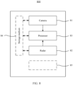
- FIG. 8 shows an autonomous driving assistance system 800 based on some embodiments.
- the system 800 includes a camera apparatus 81, a radar 82, and a processor 83.
- the camera apparatus 81 may be, for example, but is not limited to, the fisheye camera, the wide-angle camera, or the wide-field-of-view camera recorded in the foregoing embodiments.
- the radar 82 may be, for example, but is not limited to, the ultrasonic radar, the laser radar, or the millimeter-wave radar recorded in the foregoing embodiments.
- the processor 83 or the processor 72 may include, for example, but is not limited to, a central processing unit (CPU: Central Process Unit), a graphic processing unit (GPU: Graphic Processing Unit), a field programmable gate array (FPGA: Field Programmable Gate Array), a system on chip (SoC: System on Chip), an application-specific integrated chip (ASIC: Application-Specific Integrated Circuit), or a combination thereof.
- the processor 83 is configured to implement the vehicle drivable area detection method in the foregoing embodiments. For example, semantic segmentation processing is performed on image data by using a neural network, to obtain a type of an obstacle and a first probability distribution of the obstacle.
- a coordinate value of a center of the obstacle and a second probability distribution of the obstacle are determined based on a time of flight and an echo width.
- the first probability distribution of the obstacle and the second probability distribution of the obstacle are fused to obtain a drivable area of a vehicle represented by a probability, where the probability indicates a probability that the vehicle cannot drive through the area.
- the drivable area of the vehicle or the probability that the vehicle cannot drive through the area may be represented in a form of a probability grid map.
- the autonomous driving assistance system 800 may further include, for example, but is not limited to, a computer-readable storage medium 84 shown in FIG. 7 .
- the computer-readable storage medium 84 stores an instruction set, and the instruction set includes instructions required for implementing one or more of the following functions: the neural network described in the foregoing embodiments, calculation of a position and a probability of an obstacle by using radar data, and fusion performed based on obstacle probability distributions obtained by a camera apparatus or fusion based on obstacle probability distributions obtained by a radar.
- the camera apparatus 81, the radar 82, and the processor 83 may be communicatively connected to the storage medium 84.
- the autonomous driving assistance system 800 may implement the technical solutions described in the foregoing embodiments.
- the autonomous driving assistance system 800 may further include one or more other function modules/apparatuses 85 (as shown by a dashed line in FIG. 8 ).
- the function module 85 may be a display apparatus, and the display apparatus may display a probability grid map.
- the autonomous driving assistance system 800 may be disposed on, for example, the vehicle 100 with an autonomous driving function shown in FIG. 1 .
- a robot is further provided.
- the robot may include the autonomous driving assistance system provided in embodiments of this application.
- a camera apparatus and a radar may be disposed on the robot, surrounding obstacle information may be obtained based on the technical solutions described in embodiments of this application, and a route of the robot is properly planned based on the obtained obstacle information.
- the embodiments of this application provide a vehicle drivable area detection method, a system, and an autonomous driving vehicle using the system.
- a plurality of sensors are used, and obstacle probability information obtained based on the plurality of sensors is fused to obtain a probability grid map, so that a drivable area around a vehicle can be more accurately recognized.
- obstacle parallax information, an obstacle mapping method, and other manners are used, so that the technical solutions of this application can be highly generalized, and are widely applicable to a plurality of scenarios, without depending on training data. Therefore, the technical solutions of this application are robust. To sum up, the technical solutions of this application are widely applicable to autonomous driving solutions, systems, and vehicles at different levels.
- the disclosed system, apparatus, and method may be implemented in other manners.
- the described apparatus embodiments are merely examples.
- division into the units is merely logical function division.
- a plurality of units or components may be combined or integrated into another system, or some features may be ignored or not performed.
- the displayed or discussed mutual couplings or direct couplings or communication connections may be implemented through some interfaces.
- the indirect couplings or communication connections between the apparatuses or units may be implemented in electronic, mechanical, or other forms.
- the units described as separate parts may or may not be physically separate, and parts displayed as units may or may not be physical units, in other words, may be located in one position, or may be distributed on a plurality of network units. Some or all of the units may be selected based on actual requirements to achieve the objectives of the solutions of embodiments.
- functional units in embodiments of this application may be integrated into one processing unit, or each of the units may exist alone physically, or two or more units may be integrated into one unit.
- the integrated unit may be implemented in a form of hardware, or may be implemented in a form of a software service unit.
- the integrated unit When the integrated unit is implemented in the form of the software service unit and sold or used as an independent product, the integrated unit may be stored in a computer-readable storage medium. Based on such an understanding, the technical solutions of this application essentially, or the part contributing to the conventional technology, or all or some of the technical solutions may be implemented in the form of a software product.
- the computer software product is stored in a storage medium and includes several instructions for indicating a computer device (which may be a personal computer, a server, a network device, or the like) to perform all or some of the steps of the method described in embodiments of this application.
- the foregoing storage medium includes any medium that can store program code, such as a USB flash drive, a hard disk, a removable hard disk, a read-only memory (ROM, Read-Only Memory), a random access memory (RAM, Random Access Memory), a cache, an electrically programmable ROM (EPROM) memory, an electrically erasable programmable ROM (EEPROM) memory, a register, a flash memory, a magnetic disk, or an optical disc.
- program code such as a USB flash drive, a hard disk, a removable hard disk, a read-only memory (ROM, Read-Only Memory), a random access memory (RAM, Random Access Memory), a cache, an electrically programmable ROM (EPROM) memory, an electrically erasable programmable ROM (EEPROM) memory, a register, a flash memory, a magnetic disk, or an optical disc.
- the services described in this application may be implemented by hardware, software, firmware, or any combination thereof.
- the services When the services are implemented by software, the services may be stored in a computer-readable medium or transmitted as one or more instructions or code in the computer-readable medium.
- the computer-readable medium includes a computer storage medium and a communication medium, where the communication medium includes any medium that enables a computer program to be transmitted from one place to another.
- the storage medium may be any available medium accessible to a general-purpose or a special-purpose computer.
Landscapes
- Engineering & Computer Science (AREA)
- Physics & Mathematics (AREA)
- Theoretical Computer Science (AREA)
- General Physics & Mathematics (AREA)
- Remote Sensing (AREA)
- Radar, Positioning & Navigation (AREA)
- Evolutionary Computation (AREA)
- Data Mining & Analysis (AREA)
- Multimedia (AREA)
- Artificial Intelligence (AREA)
- General Engineering & Computer Science (AREA)
- General Health & Medical Sciences (AREA)
- Health & Medical Sciences (AREA)
- Computing Systems (AREA)
- Software Systems (AREA)
- Life Sciences & Earth Sciences (AREA)
- Automation & Control Theory (AREA)
- Computer Vision & Pattern Recognition (AREA)
- Databases & Information Systems (AREA)
- Molecular Biology (AREA)
- Computational Linguistics (AREA)
- Biophysics (AREA)
- Mathematical Physics (AREA)
- Biomedical Technology (AREA)
- Medical Informatics (AREA)
- Computer Networks & Wireless Communication (AREA)
- Electromagnetism (AREA)
- Library & Information Science (AREA)
- Evolutionary Biology (AREA)
- Bioinformatics & Computational Biology (AREA)
- Bioinformatics & Cheminformatics (AREA)
- Human Computer Interaction (AREA)
- Transportation (AREA)
- Mechanical Engineering (AREA)
- Probability & Statistics with Applications (AREA)
- Traffic Control Systems (AREA)
- Control Of Position, Course, Altitude, Or Attitude Of Moving Bodies (AREA)
- Image Analysis (AREA)
Abstract
Description
- This application relates to the autonomous driving field, and in particular, to a vehicle drivable area detection method, a system, and an autonomous driving vehicle using the system.
- With rapid development of 5G communication and internet of vehicles technologies, autonomous driving technologies have become a hot research topic. Core technologies in the autonomous driving field include intelligent environment perception, autonomous navigation and positioning, driving behavior decision-making, intelligent path planning and control, and the like. In the autonomous driving technologies, vehicle drivable area detection is a basic requirement for implementing autonomous driving. A vehicle needs to recognize drivable areas and non-drivable areas before route planning. In some specific autonomous driving assistance functions (for example, parking), drivable area recognition is particularly important. Autonomous parking is used as an example, and the following conditions need to be met: (1) The vehicle finds a feasible route from a current position to a target parking spot in an environment including various obstacles; and (2) the vehicle does not collide with moving or static obstacles during driving. Therefore, requirements for a vehicle-mounted sensor system are high. A sensor should provide coordinate information of an obstacle relative to the vehicle in a current environment as accurately as possible, to recognize a drivable area of the vehicle in the environment.
- In the conventional technology, the sensor is usually configured to obtain and analyze surrounding environment information of the vehicle, to obtain a drivable environment around the vehicle. However, drivable area recognition is usually not accurate enough in the conventional technology. Therefore, a new vehicle drivable area detection method is needed, so that the driving environment and the drivable area around the vehicle can be more accurately recognized.
- According to a first aspect of this application, a vehicle drivable area detection method is provided, including: processing, by using a neural network, image data obtained by a camera apparatus, to obtain a first probability distribution of an obstacle; obtaining a second probability distribution of the obstacle based on a time of flight and an echo width of a radar echo signal; and obtaining, based on the first probability distribution of the obstacle and the second probability distribution of the obstacle, a drivable area of a vehicle represented by a probability, where the probability indicates a probability that the vehicle cannot drive through the area. In the method in this application, two sensors: a camera apparatus and a radar are integrated, obstacle distribution information obtained by the two sensors is fused, and the drivable area of the vehicle obtained after fusion is represented in a form of a probability. Therefore, information about the obstacle around the vehicle can be comprehensively obtained, and a detection blind spot caused by a blind spot of the camera apparatus or a detection range of the radar is avoided. In addition, the drivable area of the vehicle is represented in a form of a probability, so that the vehicle has a more comprehensive understanding of the drivable area around the vehicle. That is, the area around the vehicle is not either capable of driving or incapable of driving, some areas may be capable of driving under a specific condition. In this way, navigation planning of the vehicle is more flexible.
- With reference to a possible implementation of the first aspect, the camera apparatus includes at least one of the following: a fisheye camera, a wide-angle camera, and a wide-field-of-view camera. The radar echo signal includes an echo signal of at least one of the following radars: an ultrasonic radar, a laser radar, or a millimeter-wave radar. Alternatively, any other suitable apparatus or radar may be used in the technical solutions of this application.
- With reference to a possible implementation of the first aspect, the radar may be disposed on the vehicle, or may be disposed on apparatuses on two sides of a road, and the camera may be disposed on the vehicle, or may be disposed on apparatuses on two sides of a road. The apparatuses on the two sides of the road may include but are not limited to a roadside lamp post, a speed measuring rod, a communication base station tower, and the like. The vehicle may obtain the information about the obstacle around the vehicle completely by using the camera apparatus and the radar that are disposed on the vehicle, or may obtain the information about the obstacle around the vehicle jointly by using some sensors (for example, only the camera apparatus is disposed) disposed on the vehicle and other sensors disposed on the apparatuses on the two sides of the road.
- With reference to another possible implementation of the first aspect, the recognized drivable area of the vehicle or the probability that the vehicle cannot drive through the area may be represented by using a probability grid map. On the probability grid map, each grid includes a probability value, and the probability value indicates a probability that the vehicle can drive in the grid. A probability distribution of the drivable area around the vehicle can be clearly expressed through the probability grid map. This provides an accurate basis for subsequent route planning. The probability grid map may be displayed on a display apparatus (for example, but not limited to a central control screen in a cockpit) of the vehicle, to intuitively provide a reference indication for a driver. The probability grid map may also be sent to an autonomous driving assistance system of the vehicle, so that the autonomous driving assistance system obtains the information about the obstacle around the vehicle.
- With reference to another possible implementation of the first aspect, semantic segmentation processing may be performed, by using the neural network, on image data obtained by using a fisheye camera. Specifically, an image may be first transformed into a top view, and then semantic segmentation processing is performed on a transformed image. After the image is transformed into the top view, an environment around the vehicle can be comprehensively shown. Semantic segmentation processing may be performed on the transformed image by using the neural network, that is, classification of different objects/people in the image is determined based on recognition of the neural network. For example, the neural network may be used to determine a part in the image that is a building and another part in the image that is a vehicle. More specifically, a neural network including an encoder-decoder (Encoder-Decoder) structure may be used to perform the foregoing semantic segmentation process on the image. An encoder performs dimension reduction on data by using a pooling layer, and a decoder performs dimension increase on the data by using a deconvolutional layer. Through the dimension reduction-dimension increase process, semantic segmentation can be performed on the image, and details of the image can be retained as much as possible. Through the foregoing semantic segmentation process of the image by using the neural network, an object/person in the environment around the vehicle can be recognized, so that a distribution of obstacles around the vehicle can be better determined.
- With reference to another possible implementation of the first aspect, a plurality of frames of images that are adjacent or spaced in terms of time may be input into the neural network for recognition. Parallax information of a same object in different image frames may be used as a recognition feature of the neural network by using the plurality of frames of images that are adjacent or spaced in terms of time, so that the neural network can better recognize the object in the image. Output of the neural network includes a type of the obstacle, and the first probability distribution of the obstacle can be determined based on the type of the obstacle.
- With reference to another possible implementation of the first aspect, in a process of training the neural network, an obstacle mapping method may be used. The obstacle mapping method means that an obstacle close to the vehicle is manually "mapped" in a training image of the neural network. In this method, a large amount of recognition information about the obstacle close to the vehicle can be obtained in the training process of the neural network, so that if there is an actual obstacle around the vehicle subsequently, a problem that the obstacle cannot be recognized or the obstacle is wrongly recognized because a training set does not include such data (the obstacle close to the vehicle) is avoided.
- With reference to another possible implementation of the first aspect, in a loss function of the neural network, a high weight is given to a loss function of a small obstacle. With this setting, the neural network may be more "sensitive" to recognition of the small obstacle, because in practice, most vehicle collisions are not caused by a large obstacle (for example, another vehicle) but a small obstacle (for example, a roadside parking lock).
- With reference to another possible implementation of the first aspect, a plurality of radars distributed around the vehicle are used to obtain an echo signal and a time of flight of the obstacle around the vehicle. If the radars are ultrasonic radars and the ultrasonic radars are set around the vehicle, when an obstacle is on the right side of the vehicle, an ultrasonic radar on the right side of the vehicle is used, and when an obstacle is on the left side of the vehicle, an ultrasonic radar on the left side of the vehicle is used. If the radars are laser radars and are set on the top of the vehicle, information about obstacles within 360 degrees around the vehicle can be obtained by using the laser radars on the top of the vehicle. A quantity of radars may be set according to a specific requirement. Usually, 6 to 16 ultrasonic radars, and/or 1 to 4 laser radars, and/or 1 to 4 millimeter-wave radars may be disposed on one vehicle. Based on the obtained echo signal and time of flight, a coordinate value of a center of the obstacle in a vehicle reference coordinate system can be determined based on a radar wave velocity by using a geometric method.
- With reference to another possible implementation of the first aspect, a geometric size of the obstacle may be determined based on an echo width and a time of flight of a single radar, because the obstacle cannot be a "point" in a geometric sense, and the obstacle has a specific geometric size. However, a sound wave/electromagnetic wave emitted by a same radar may be reflected back at different positions of the obstacle in different times. The size of the obstacle may be generally determined based on the echo width and different times of flight. After the size of the obstacle is generally determined, the obstacle may be abstracted/simplified into a circle with a radius of r. A center of the circle corresponds to the coordinate value of the center of the obstacle in the vehicle reference coordinate system. Probabilities are distributed from the center of the circle to a circumference in a linear decreasing manner by using the center of the circle as a center and the circumference as an edge. Coordinates of the center of the circle correspond to the coordinate value of the center of the obstacle in the vehicle reference coordinate system. A probability at the center of the circle is the highest, and a probability at the circumference is the lowest.
- With reference to another possible implementation of the first aspect, a fusion weight function may be used in combination with the probability distributions of the obstacle generated by using the camera and the radar, to obtain the probability grid map. Specifically, the following fusion weight function may be selected:

- Herein, dmax represents a boundary distance that can be detected by using the radar.
- A probability value of a fused target grid point is:
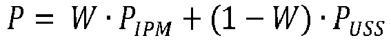
- PIPM represents the probability distribution of the obstacle obtained by using the camera, and PUSS represents the probability distribution of the obstacle obtained by using the radar. The camera may include a fisheye camera, and the radar may include at least one of an ultrasonic radar, a laser radar, and a millimeter-wave radar.
- According to a second aspect, an embodiment of this application further provides an autonomous driving assistance system. The system includes: a camera apparatus, where the camera apparatus is configured to obtain image data; at least one radar, where the radar is configured to obtain a radar echo signal; and a processor, where the processor is configured to perform the following operations: processing, by using a neural network, the image data obtained by the camera apparatus, to obtain a first probability distribution of an obstacle; obtaining a second probability distribution of the obstacle based on a time of flight and an echo width of a radar echo signal; and obtaining, based on the first probability distribution of the obstacle and the second probability distribution of the obstacle, a drivable area of a vehicle represented by a probability, where the probability is a probability that the vehicle cannot drive through the area.
- It may be understood that the system provided in the second aspect corresponds to the method provided in the first aspect. Therefore, for implementations of the second aspect and technical effects that can be achieved by the implementations of the second aspect, refer to related descriptions of the implementations of the first aspect.
- With reference to another possible implementation of the second aspect, the system further includes a display apparatus, and the display apparatus is configured to display a probability grid map.
- According to a third aspect, an autonomous driving vehicle is provided, including the autonomous driving assistance system in the second aspect.
- According to a fourth aspect, an embodiment of this application provides a computer-readable storage medium, including an instruction set. The instruction set may be executed by a processor to implement the method according to any implementation of the first aspect.
- Various embodiments of this application provide a vehicle drivable area detection method, an autonomous driving assistance system, and an autonomous driving vehicle including the system. In embodiments of this application, a plurality of sensors are used to obtain information about an environment and an obstacle around a vehicle, the obtained information is fused based on different features of different sensors, and the information is presented in a form of a probability grid map, so that a drivable area around the vehicle can be more accurately recognized. In another aspect, in this application, manners such as obstacle parallax information and obstacle mapping are used, so that the technical solutions in this application can have high generalization, are widely applicable to a plurality of scenarios, and do not depend on training data. Therefore, the technical solutions in this application are robust, and can be widely applicable to different levels of autonomous driving solutions, systems, and vehicles. In still another aspect, the technical solutions of this application are particularly applicable to an autonomous driving scenario in which there are a large quantity of obstacles around a vehicle, for example, an autonomous parking scenario.
-
-
FIG. 1 is a schematic diagram of a structure of an autonomous driving vehicle according to an embodiment of this application; -
FIG. 2 is a schematic diagram of obstacle recognition based on image data according to an embodiment of this application; -
FIG. 3 is a schematic diagram of an obstacle mapping method according to an embodiment of this application; -
FIG. 4 is a schematic diagram of determining obstacle coordinates based on radar data according to an embodiment of this application; -
FIG. 5 is a schematic diagram of determining a size and a probability distribution of an obstacle based on radar data according to an embodiment of this application; -
FIG. 6 is a schematic diagram of performing drivable area fusion based on image data and radar data according to an embodiment of this application; -
FIG. 7 is a schematic diagram of a computer-readable storage medium and a processor according to an embodiment of this application; and -
FIG. 8 is a schematic diagram of a structure of an autonomous driving assistance system according to an embodiment of this application. - Embodiments of this application provide a vehicle drivable area detection method, a system, and a parking apparatus using the system. Information is obtained by using a plurality of sensors on a vehicle, and the information is fused by using a given method, so that a drivable range around the vehicle can be accurately recognized, a new solution is provided for the vehicle drivable area detection method, and support is provided for improving autonomous driving reliability and optimizing driving experience of a user.
- Refer to
FIG. 1 . In some embodiments, avehicle 100 with an autonomous driving function is provided. Thevehicle 100 may include adrive system 101, acontrol system 102, adrive system 103, and the like. Thesensor system 101 may include, for example, but is not limited to, a global positioning system, an inertial navigation device, a laser radar, a millimeter-wave radar, and a camera. Thecontrol system 102 may include, for example, but is not limited to, a system/apparatus, for example, an autonomous driving vehicle computing platform. Thedrive system 103 may include, for example, but is not limited to, an engine, a transmission apparatus, an electric energy source, and a wire-controlled system. Thevehicle 100 may further include, but is not limited to, an autonomous driving assistance system (Advanced Driving Assistance System, ADAS for short). Thesensor system 101, thecontrol system 102, and thedrive system 103 may be communicatively connected. - With reference to
FIG. 2 to FIG. 6 , the following further describes in detail the vehicle drivable domain detection method provided in embodiments of this application. -
FIG. 2 is a schematic diagram of obstacle recognition based on image data according to an embodiment of this application. The left side ofFIG. 2 shows top views of frames T and T+1 that are adjacent in terms of time, the middle part ofFIG. 2 shows aneural network 26 used for obstacle recognition, and the right side ofFIG. 2 shows a final recognition result. The following describes an obstacle recognition process in detail. - In a scenario shown in
FIG. 2 , avehicle 21 travels on alane 20, obstacles on the left side of thevehicle 21 include apillar 24 and astatic vehicle 25, there are two parking spots 22 on the right side of thevehicle 21, and an area of each parking spot 22 further includes a parking block 23. - One or more camera apparatuses may be disposed around the
vehicle 21, and image data around thevehicle 21 may be obtained by the camera apparatus. In some embodiments, the camera apparatus configured to obtain image data may be a fisheye camera. The fisheye camera has a feature of a small blind spot, so that information around the vehicle can be obtained as much as possible. It should be understood that another type of proper camera, for example, but not limited to a common camera, a wide-angle camera, or a wide-field-of-view camera, may alternatively be used without violating the spirit of this application. - In some embodiments, a plurality of images around the vehicle are obtained by using a plurality of fisheye cameras, and the plurality of images are processed into a top view through time alignment. For autonomous driving of the vehicle, a top view may comprehensively reflect information about an overall environment around the vehicle.
- In some embodiments, a procedure for generating a top view includes: (1) performing dedistortion processing based on a distortion parameter of a camera; (2) performing perspective transformation to switch from a camera coordinate system to an image coordinate system; and (3) performing image stitching and brightness balance fusion. The three processes are described as follows.
- (1) Distortion of the camera is radial distortion caused by a special shape of a lens. In practice, if r = 0, the first several expansion items of Taylor series are usually used to approximately describe the radial distortion. Coordinates before and after the radial distortion is corrected are expressed as follows:


- (2) The generating the top view includes: converting each pixel in the top view into coordinates of a point of a corresponding world coordinate system on the ground based on a ratio of a physical size to the pixel. For the coordinates in the world coordinate system, during generation of the top view, a to-be-used image of a camera is first determined, then coordinates of the point in a camera coordinate system are obtained by using a spatial coordinate system conversion formula, and then coordinates of the point in an image coordinate system and a pixel coordinate system are obtained by formulating an intrinsic and extrinsic parameter model of the camera.
- (3) When images of a plurality of angles of view are stitched, different parts of an image obtained through stitching are prone to have luminance and color differences, and stitching parts of the image are prone to have obvious stitches (caused by color differences of imaging of different cameras in a same area). To resolve this problem, a pixel value of an overlapping area of images that are on both sides of the stitching part and obtained by cameras is used. During generation of the top view, luminance balance processing is performed, through gamma correction, on the parts of the image that have the luminance difference, the image is converted into a YUV format, luminance of parts that are of the images and that are in the overlapping area is calculated, and the luminance is adapted to a Y channel of the overall top view. The parts of the image with stitches may be processed through Alpha blending (Alpha Blending) of the image. In an implementation, any two images may be combined into one image, and a pixel value of the combined image may be obtained according to the following formula (1):

- Herein, α indicates blending transparency, and a value of α is between [0, 1]. In the overlapping area, the value of α gradually changes from 0 to 1 from one image to another image. At a stitch of the image, the value of α, for example, may be 0.5.
- After steps (1), (2), and (3), the top view of the surrounding environment of the vehicle may be obtained by using the camera apparatus around the vehicle, as shown in the left part of
FIG. 2 . - In the foregoing top view generation process, it is assumed that all pixels (including pixels of an obstacle) have a same height, for example, all pixels come from the ground. However, points of obstacles may have different heights. In a process of converting objects of different heights from three-dimensional to two-dimensional, obvious deformation occurs, and the deformation varies based on different observation angles (that is, different positions of the fisheye camera) and different heights of obstacles. A higher obstacle corresponds to larger deformation, and therefore a parallax in different image frames is more obvious. Refer to the
pillar 24 inFIG. 2 . Because thepillar 24 has a high height, thepillar 24 is greatly deformed in the top view. However, because the parking block 23 inFIG. 2 has a low height (usually, the height of the parking block 23 is about 10 to 20 cm), the parking block 23 basically does not deform in the top view. In the technical solutions of this application, parallax information is used as a part of input of theneural network 26, so that the neural network can better recognize an obstacle. - The
neural network 26 may use an encoder-decoder (Encoder-Decoder) architecture, for example, an encoder and a decoder. The encoder is configured to perform dimension reduction on data by using a pooling layer. The decoder is configured to perform dimension increasing on data by using a deconvolutional layer. The encoder is configured to recognize a texture feature of the obstacle, and the decoder is configured to better restore details of the obstacle. Although the encoder-decoder architecture is used in some embodiments, the neural network in the solutions of this application is not limited to the architecture. Any other suitable neural network (for example, including but not limited to using a convolution-pooling-fully connected architecture) may be selected based on an actual situation without violating the spirit of this application. - In a conventional process of recognizing an image by using the neural network, a texture feature of an object in an image frame is usually used for object recognition (semantic segmentation). However, as described above, object parallax information in different frames of the top view may be used as a characterization feature of an obstacle. In this application, input of the neural network is not limited to a single-frame image, and further includes a plurality of frames of associated images in terms of time, for example, T and T+1 frames of images shown in
FIG. 2 . The two frames of images are adjacent in terms of time. The neural network recognizes information about obstacle by using parallax information of the obstacle in the images that are adjacent in terms of time in combination with a conventional texture-based obstacle recognition method. An advantage brought by introducing parallax information is that a trained model can be better generalized to a scenario that does not exist in a model training set. Because it is difficult for a training dataset to include shapes of all possible obstacles, the neural network learning based on a texture feature has a problem of difficult generalization. Deformation caused by a parallax is a general rule of physics. Through learning parallax information to determine obstacles, a neural network model is enabled to have a better generalization capability, that is, the neural network model can be applied to a plurality of different scenarios based on a small amount of training data. It should be understood that, although obstacle recognition is described in the foregoing embodiment by using a pair of images that are adjacent in terms of time, in some other implementations, obstacle recognition may alternatively be performed based on an actual situation by using a pair of images having a specific interval of frames in terms of time. For example, a pair of images at a moment T and a moment T+2 (with an interval of one frame) or a pair of images at a moment T and a moment T+3 (with an interval of two frames) may be used for obstacle recognition. When a speed of the vehicle is high, nearest neighboring images on a time frame may be selected for input, because when the speed of the vehicle is high, a parallax of an object in a short time interval may be obvious. In addition, when the speed of the vehicle is low, images with an interval of two frames, three frames, or more frames on the time frame may be selected for input. - In some embodiments, semantic segmentation is performed on the image frame by using the
neural network 26, that is, obstacles in the image frame are recognized and classified. For example, image areas may be classified into three types. - (1) Freespace (Freespace) is an area in which the vehicle may travel freely. For example, the
lane 20 belongs to the freespace. - (2) A high obstacle (High Obstacle) area is an area in which the vehicle cannot travel. For example, the
pillar 24 belongs to the high obstacle area. - (3) A low obstacle (Low Obstacle) area is an area in which the vehicle does not travel in most cases but may travel in a special case. For example, the parking block 23 belongs to the low obstacle area, and the vehicle may pass (roll over) the parking block 23.
- It should be understood that the foregoing classification of semantic segmentation is based on examples of embodiments, and a person skilled in the art may use a proper semantic segmentation type based on an actual requirement without violating the spirit of this application.
- In some embodiments, an obstacle probability distribution diagram may be obtained based on a semantic segmentation type of an obstacle that is output by the neural network, to represent a non-drivable area of the vehicle or a drivable area of the vehicle. In some other embodiments, a probability grid map may be used to represent a non-drivable area of the vehicle or a drivable area of the vehicle.
FIG. 2 is used as an example. The right side ofFIG. 2 shows a probability grid map in this embodiment. Each grid point in the probability grid map has its own probability value, and the probability value of each grid point represents a probability that the grid point is an obstacle (that is, the vehicle cannot drive through an area). For example, anarea 28 and anarea 29 shown by dashed lines inFIG. 2 represent high obstacle areas (the vehicle and the pillar) recognized by the neural network, and the areas are non-drivable for thevehicle 21. A probability value of grid points in thearea 28 and thearea 29 inFIG. 2 may be set to 1. Anarea 27 inFIG. 2 represents a low obstacle area (the parking block) recognized by the neural network, and the area is drivable for thevehicle 21. Therefore, a probability value of grid points in thearea 27 may be set to a number between 0 to 1 according to a requirement. However, theroad area 21 inFIG. 2 is recognized as freespace, and a probability value of grid points in the road area may be set to 0. In some other embodiments, a probability value may be set opposite to the probability value in the foregoing embodiment, that is, the probability value represents a probability that the vehicle can drive through the area. - In some embodiments, when the probability value represents that the vehicle cannot drive through the area, if high security needs to be ensured, all grid points at which a probability is not 0 may be set as non-drivable areas of the vehicle. In this case, there are two types of areas in the probability grid map: drivable area and non-drivable area.
- On a road or a driving area, because a small obstacle (for example, a traffic cone or a tire) occupies a small area/volume, in a neural network training process, even if a determining error occurs, a cost value of a loss function is small. As a result, the neural network has low sensitivity to recognizing the small obstacle, and the small obstacle may be difficult to be recognized. Compared with a large obstacle, it is difficult for a vehicle driver or an autonomous driving assistance system to perceive/recognize a small obstacle. Therefore, a small obstacle is more likely to cause a collision with the vehicle. To resolve this problem, in some embodiments, in a training process of the
neural network 26, compared with a large obstacle, a high weight is given to a small obstacle in the loss function. In some embodiments, the loss function may be adjusted by using formula (2):
- A is an adjustment parameter. In some embodiments, A may be a selected value from 8 to 12, and A may be an integer, for example, 10, or may be a decimal, for example, 9.5.
- Herein, loss segmentation and losssmall_obstacle may be functions learned in the machine learning field, for example, (but not limited to) Sigmoid, L1-loss, and L2-loss, and loss segmentation is a loss function used for calculating pixels in different segmentation areas (for example, the freespace, the high obstacle area, or the low obstacle area) after semantic segmentation is performed on the image, and losssmall_obstacle is a loss function used for calculating pixels of a small obstacle in the image. When there is a small obstacle, the overall loss function Loss may be large (higher than a loss function when no small obstacle occurs) by combining loss segmentation and losssmall_obstacle. Therefore, in this embodiment of this application, the neural network has a high probability of recognizing a small obstacle.
- In some embodiments, the small obstacle includes but is not limited to a common object on the road, for example, a conical tube, a wheel stop, or a parking lock. From an image perspective, if pixels of an object in a top view are fewer than 300 pixels, the object may also be considered as a small obstacle.
- Through the foregoing adjustment, the trained
neural network 26 in this application can have a better recognition capability for a small obstacle. - During data collection, there are few short-distance obstacles or direct collisions between obstacles and vehicles. Therefore, in a current image training sample, almost no obstacle appears in a short-distance range of the vehicle. As a result, there is a lack of the obstacle (image) training sample in a short-distance surrounding area of the vehicle. This lack makes the neural network overfit and output a recognition result that the surrounding area of the vehicle is a drivable area, even if there is an obstacle in the surrounding area of the vehicle.
- To resolve a training problem caused by unbalanced data distribution (that is, the lack of the obstacle training sample in the short-distance surrounding area of the vehicle), in some embodiments, an obstacle mapping method is introduced for data augmentation, to improve a detection rate of a near obstacle.
-
FIG. 3 is a schematic diagram of an obstacle mapping method. A surrounding environment of avehicle 31 includes an actual obstacle shown by a dashedline range 32. Anobstacle 33 may be "mapped" into an image before the image is sent to a neural network for learning. Theobstacle 33 is not an obstacle existing in an actual scenario, but is virtually "mapped" into the image. An image obtained through mapping is sent to the neural network for training of the neural network. In this way, when there is no short-distance obstacle in the actual scenario, the neural network can be well trained, and therefore, an overfitting phenomenon does not occur in the neural network. - In some embodiments, an obstacle is randomly mapped into an area range around the vehicle, and a rotation angle of the obstacle changes based on an angle range of a camera in which the obstacle is captured, to avoid an unreal image. In some embodiments, a type of the obstacle may be randomly selected, for example, but is not limited to a roadblock, a cart, an animal, or a pedestrian.
-
FIG. 4 andFIG. 5 are schematic diagrams of recognizing obstacles by using radars according to embodiments. In some embodiments, ultrasonic radars may be used. There may be 6 to 12 ultrasonic radars disposed around thevehicle 21 usually, which may include long-range radars and short-range radars. -
FIG. 4 is a schematic diagram of recognizing an obstacle by using two ultrasonic radars. An ultrasonic radar S2 is driven to transmit a signal, and the ultrasonic signal is received by S1 and S2 after being reflected by anobstacle 41. Relative positions of theobstacle 41 and the ultrasonic radars S1 and S2 may be positioned based on different times of flight TOFs (Times of Flight). Further, coordinates of a center of the obstacle relative to a vehicle reference coordinate system may be obtained by using a triangulation position method. For a specific calculation process, refer to the following descriptions. - If S2 emits a wave and S1 and S2 receive valid echoes, distances between the
obstacle 41 and S2 and between theobstacle 41 and S1 are given by the following formula (3):
- TOF 1 and TOF 2 respectively represent times of flight obtained by the ultrasonic radars S1 and S2, and vuss represents a propagation speed of a sound wave at a normal temperature.
- Therefore, a specific coordinate value (xobj,yobj ) of the center of the
obstacle 41 in the vehicle reference coordinate system may be calculated according to the following formula (4):
- Herein, (x 1,y 1) and (x 2,y 2) are respectively coordinate values of the ultrasonic radars S1 and S2 relative to the vehicle reference coordinate system.
- In some embodiments, as shown in
FIG. 5 , a single ultrasonic radar may be used to send an ultrasonic wave and receive an echo signal, to obtain an echo width of the echo signal and a time of flight. A geometric shape of an obstacle may be obtained based on the echo width and the time of flight. In some embodiments, for convenience, the obstacle may be abstractly defined as a circle with a radius of r on a two-dimensional plane, and coordinates of a center of the circle corresponds to the center of the obstacle recognized by the two ultrasonic radars, the radius r of the circle may be determined by using the following formula (5):
- Herein, ECHO 1 represents the echo width, d 1 represents a shortest echo distance, and d 2 represents a longest echo distance. Because the obstacle has a specific geometric size, the ultrasonic wave is reflected by different parts of the obstacle, so that the ultrasonic wave has the shortest echo distance d 1 and the longest echo distance d 2.
- It should be understood that, in this embodiment, for convenience, the obstacle is abstractly defined as the circle with the radius of r, and a person skilled in the art may also abstractly define the obstacle as another proper geometric shape, for example, a rectangle or a polygon.
- In some embodiments, linear probability distribution is performed on the geometric circle of the recognized obstacle. Specifically, it is determined that the center of the circle corresponds to a coordinate value of the center of the obstacle in the vehicle reference coordinate system. At the center of the circle, a probability of the obstacle is 100%, and the probability linearly decreases from the center radially outward to a circumference. That is, a probability of the obstacle at a radial r/2 circumference of the circle may be 50%, and a probability of the obstacle at the circumference r of the circle is 0. It should be understood that linear distribution of probabilities is an optional manner based on some embodiments, and a person skilled in the art may select another proper probability attenuation function (for example, an e exponential attenuation) based on an actual situation without violating the spirit of this application.
- In some embodiments, the foregoing obstacle probability distribution is implemented by using a gird map. The right side of
FIG. 5 shows an example diagram. Anobstacle 51 is presented as a probability distribution diagram 52 after being recognized by the ultrasonic radar. At the center of the circle, a probability is highest and a color is darkest, and at the circumference, a probability is lowest and a color is lightest. - In some embodiments, the foregoing process may be further implemented by using, for example, a laser radar or a millimeter-wave radar, provided that a sound velocity in the foregoing calculation process is replaced with a light velocity.
- In some embodiments, probability distributions of the obstacle obtained by using a fisheye camera and the ultrasonic radar may be fused by using a fusion weight function W, to obtain a probability grid map. For example, fusion processing may be performed with reference to the fusion weight function in the following formula (6). In formula (6), the fusion weight function W may be a function of a distance d, and d represents a distance between a target grid point (the obstacle) and the vehicle.

- Herein, dmax represents a boundary distance that can be detected through an ultrasonic wave.
- A probability value of a fused target grid point is given by the following formula (7):

- PIPM represents an obstacle probability distribution of a target grid point obtained by using the fisheye camera, and PUSS represents an obstacle probability distribution of a target grid point obtained by using the ultrasonic radar.
- Based on the foregoing formula (6), it can be learned that if the distance d between the obstacle and the vehicle exceeds a distance boundary that can be detected by the ultrasonic radar, W=1. When W=1, (1-W)∗PUSS in the foregoing formula (7) is 0, which indicates that the ultrasonic radar cannot effectively detect the obstacle in this case, and the vehicle obtains the probability distribution of the obstacle by using the fisheye camera.
- Based on the foregoing formula (6), it can be further learned that when d and dmax are small (for example, less than 0.2), a weight of the ultrasonic radar in formula (7) is large. This can resolve a problem that a visual recognition effect is poor due to a visual blind spot of the fisheye camera when an obstacle is close to the vehicle.
- It should be understood that the foregoing fusion weight function and fusion formula are merely implementation examples based on embodiments, and a person skilled in the art may select any another proper form of the fusion weight function and another fusion formula based on an actual situation without violating the spirit of this application.
- It should be understood that, in addition to the fisheye camera and the ultrasonic radar, a person skilled in the art may properly select another apparatus, for example, a high-precision camera, a wide-angle camera, a laser radar, or a millimeter-wave radar, based on a situation, to implement the foregoing technical process without violating the spirit of this application.
- Two-dimensional grid points obtained after the foregoing fusion form the probability grid map represented by a probability. A probability that an obstacle exists at a grid point is distributed from 0% to 100%. Based on different probabilities at the grid point, the vehicle may determine areas in which the vehicle can drive freely, areas in which the vehicle cannot drive, and areas in which the vehicle can drive in a specific case. In some embodiments, the generated probability grid map may be displayed on a cockpit display of the vehicle for reference by a driver.
- It can be learned from the foregoing descriptions that, in the technical solutions provided in embodiments of this application, the obstacle probability distributions obtained by using sensors such as the camera apparatus and the radar are combined, so that an autonomous driving vehicle using the technical solutions of this application can comprehensively obtain information about an obstacle around the vehicle, and avoid information loss caused by a blind spot or a measurement limit of a single sensor. In addition, in the technical solutions provided in embodiments of this application, in a training process of the neural network and a processing process of image information, technical means such as an obstacle mapping method, weight enhancement of a small obstacle loss function, and introduction of parallax information between consecutive image frames are used, so that the neural network in the technical solutions of this application can more accurately recognize information about an obstacle around the vehicle based on the image information.
-
FIG. 6 shows a process of recognizing an obstacle based on a combination of a fisheye camera and an ultrasonic radar in some embodiments, which is similar to the scenario inFIG. 2 (a process of a plurality of frames of images is omitted inFIG. 6 ). Herein, 64 represents a pillar, 65 represents a static vehicle, avehicle 61 travels on aroad 60, there are twoparking spots 62 on the right side of thevehicle 61, and eachparking spot 62 further includes aparking block 63. On a probability grid map on the right side ofFIG. 6 , 68 and 69 represent high obstacle areas (respectively corresponding to thepillar 64 and thestatic vehicle 65 on the left side ofFIG. 6 ), and 67 represents a low obstacle area (corresponding to the parking block 23 on the left side ofFIG. 6 ). Different from the scenario inFIG. 2 , a low obstacle A (for example, but not limited to a robotic vacuum cleaner) that is close to the vehicle exists on theroad 60. A camera has a blind spot, and a height of the robotic vacuum cleaner may be very low. Therefore, if a surrounding environment of the vehicle is recognized only by using the fisheye camera, the obstacle A may be missed or cannot be recognized. In this embodiment, the ultrasonic radar is combine. The ultrasonic radar may obtain a position and a geometric shape of the obstacle A through positioning and size recognition in the foregoing embodiments, and define the position and the geometric shape as a circular obstacle probability distribution with a radius of r. The probability grid map shown on the right side ofFIG. 6 may be obtained by combining obstacle probability distribution information recognized by the ultrasonic radar and obstacle probability distribution information recognized by the fisheye camera, and shows a probability distribution of the obstacle A. In some embodiments, the probability grid map may be further transmitted to an autonomous driving assistance system (Advanced Driving Assistance System) of the vehicle. Therefore, the ADAS system can "learn", based on the obtained probability grid map, that there is an obstacle in a front-right road area. Therefore, the ADAS system can properly avoid the obstacle during route planning. In some other embodiments, if a human driver is driving the vehicle, the probability grid map may alternatively be displayed on a display of a cockpit of the vehicle, to prompt the driver that there is an obstacle in the road area on the front right and the driver should perform proper avoidance. - In the foregoing embodiments, both the camera apparatus and the radar are disposed on a same vehicle. In some other embodiments, the camera apparatus and the radar may alternatively be separately disposed on different vehicles. For example, a camera apparatus is disposed on a vehicle A, a radar is disposed on a vehicle B, and the vehicles A and B communicate with each other and transfer/exchange respective information or obtained information through a communications network. In this way, even if only one type of sensor is disposed on the vehicle A or the vehicle B, the vehicle A or the vehicle B may obtain information about two types of sensors under a specific condition, and further obtain information about an obstacle around the vehicle according to the technical solutions disclosed in embodiments of this application.
- In some other embodiments, in a vehicle-road collaboration scenario, the camera apparatus and/or the radar may alternatively be disposed on a road or an apparatus around a road. For example, the camera apparatus may be disposed on a telegraph pole or a monitoring apparatus around a road. For another example, the camera apparatus and/or the camera apparatus may be disposed on an apparatus, for example, a lamp post, a speed measuring pole, or a communication base station tower on a road side. The camera apparatus and/or the radar may communicate with a vehicle through, for example, V2X (Vehicle to Everything), and transmit obtained information to the vehicle. Based on vehicle-road collaboration, the vehicle may be provided with only one type of sensor (for example, equipped with only a camera apparatus), or may obtain information about two types of sensors under a specific condition, and further obtain information about an obstacle around the vehicle according to the technical solutions disclosed in embodiments of this application.
-
FIG. 7 shows a computer-readable storage medium 71 based on some embodiments. The computer-readable storage medium 71 stores aninstruction set 73. Theinstruction set 73 may include the neural network described in the foregoing embodiments, obstacle position and probability calculation performed by using radar data, and logic for fusing an obstacle probability distribution obtained by using a camera apparatus and an obstacle probability distribution obtained by using a radar. The computer-readable storage medium 71 is configured to be communicatively connected to aprocessor 72. Theprocessor 72 may be communicatively connected to acamera apparatus 74 and a radar 75 (shown by dashed lines inFIG. 7 ). After obtaining data of thecamera apparatus 74 and theradar 75, theprocessor 72 may process the data based on the instruction set stored in the computer-readable storage medium 71, to implement the technical solutions in the foregoing embodiments. Theprocessor 72 may include, for example, but is not limited to, a central processing unit (CPU: Central Process Unit), a graphic processing unit (GPU: Graphic Process Unit), a field programmable gate array (FPGA: Field Programmable Gate Array), a system on chip (SoC: System on Chip), an application-specific integrated chip (ASIC: Application-Specific Integrated Circuit), or a combination thereof. -
FIG. 8 shows an autonomousdriving assistance system 800 based on some embodiments. Thesystem 800 includes acamera apparatus 81, aradar 82, and aprocessor 83. Thecamera apparatus 81 may be, for example, but is not limited to, the fisheye camera, the wide-angle camera, or the wide-field-of-view camera recorded in the foregoing embodiments. Theradar 82 may be, for example, but is not limited to, the ultrasonic radar, the laser radar, or the millimeter-wave radar recorded in the foregoing embodiments. Theprocessor 83 or theprocessor 72 may include, for example, but is not limited to, a central processing unit (CPU: Central Process Unit), a graphic processing unit (GPU: Graphic Processing Unit), a field programmable gate array (FPGA: Field Programmable Gate Array), a system on chip (SoC: System on Chip), an application-specific integrated chip (ASIC: Application-Specific Integrated Circuit), or a combination thereof. Theprocessor 83 is configured to implement the vehicle drivable area detection method in the foregoing embodiments. For example, semantic segmentation processing is performed on image data by using a neural network, to obtain a type of an obstacle and a first probability distribution of the obstacle. A coordinate value of a center of the obstacle and a second probability distribution of the obstacle are determined based on a time of flight and an echo width. The first probability distribution of the obstacle and the second probability distribution of the obstacle are fused to obtain a drivable area of a vehicle represented by a probability, where the probability indicates a probability that the vehicle cannot drive through the area. The drivable area of the vehicle or the probability that the vehicle cannot drive through the area may be represented in a form of a probability grid map. The autonomousdriving assistance system 800 may further include, for example, but is not limited to, a computer-readable storage medium 84 shown inFIG. 7 . The computer-readable storage medium 84 stores an instruction set, and the instruction set includes instructions required for implementing one or more of the following functions: the neural network described in the foregoing embodiments, calculation of a position and a probability of an obstacle by using radar data, and fusion performed based on obstacle probability distributions obtained by a camera apparatus or fusion based on obstacle probability distributions obtained by a radar. Thecamera apparatus 81, theradar 82, and theprocessor 83 may be communicatively connected to thestorage medium 84. Through the foregoing setting, the autonomousdriving assistance system 800 may implement the technical solutions described in the foregoing embodiments. It should be understood that, in some embodiments, the autonomousdriving assistance system 800 may further include one or more other function modules/apparatuses 85 (as shown by a dashed line inFIG. 8 ). For example, thefunction module 85 may be a display apparatus, and the display apparatus may display a probability grid map. In some embodiments, the autonomousdriving assistance system 800 may be disposed on, for example, thevehicle 100 with an autonomous driving function shown inFIG. 1 . - In some other embodiments, a robot is further provided. The robot may include the autonomous driving assistance system provided in embodiments of this application. To be specific, a camera apparatus and a radar may be disposed on the robot, surrounding obstacle information may be obtained based on the technical solutions described in embodiments of this application, and a route of the robot is properly planned based on the obtained obstacle information.
- The embodiments of this application provide a vehicle drivable area detection method, a system, and an autonomous driving vehicle using the system. In the technical solutions of this application, a plurality of sensors are used, and obstacle probability information obtained based on the plurality of sensors is fused to obtain a probability grid map, so that a drivable area around a vehicle can be more accurately recognized. In addition, in this application, obstacle parallax information, an obstacle mapping method, and other manners are used, so that the technical solutions of this application can be highly generalized, and are widely applicable to a plurality of scenarios, without depending on training data. Therefore, the technical solutions of this application are robust. To sum up, the technical solutions of this application are widely applicable to autonomous driving solutions, systems, and vehicles at different levels.
- In the specification, claims, and accompanying drawings of this application, the terms "first", "second", "third", "fourth", and so on (if existent) are intended to distinguish between similar objects but do not necessarily indicate a specific order or sequence. It should be understood that the data termed in such a way are interchangeable in proper circumstances so that embodiments of the present invention described herein can be implemented in other orders than the order illustrated or described herein. In addition, the terms "include" and "have" and any other variants are intended to cover the non-exclusive inclusion. For example, a process, method, system, product, or device that includes a list of steps or units is not necessarily limited to those expressly listed steps or units, but may include other steps or units not expressly listed or inherent to such a process, method, product, or device.
- It may be clearly understood by a person skilled in the art that, for the purpose of convenient and brief description, for a detailed working process of the foregoing system, apparatus, and unit, refer to a corresponding process in the foregoing method embodiments, and details are not described herein again.
- In embodiments provided in this application, it should be understood that the disclosed system, apparatus, and method may be implemented in other manners. For example, the described apparatus embodiments are merely examples. For example, division into the units is merely logical function division. During actual implementation, there may be another division manner. For example, a plurality of units or components may be combined or integrated into another system, or some features may be ignored or not performed. In addition, the displayed or discussed mutual couplings or direct couplings or communication connections may be implemented through some interfaces. The indirect couplings or communication connections between the apparatuses or units may be implemented in electronic, mechanical, or other forms.
- The units described as separate parts may or may not be physically separate, and parts displayed as units may or may not be physical units, in other words, may be located in one position, or may be distributed on a plurality of network units. Some or all of the units may be selected based on actual requirements to achieve the objectives of the solutions of embodiments.
- In addition, functional units in embodiments of this application may be integrated into one processing unit, or each of the units may exist alone physically, or two or more units may be integrated into one unit. The integrated unit may be implemented in a form of hardware, or may be implemented in a form of a software service unit.
- When the integrated unit is implemented in the form of the software service unit and sold or used as an independent product, the integrated unit may be stored in a computer-readable storage medium. Based on such an understanding, the technical solutions of this application essentially, or the part contributing to the conventional technology, or all or some of the technical solutions may be implemented in the form of a software product. The computer software product is stored in a storage medium and includes several instructions for indicating a computer device (which may be a personal computer, a server, a network device, or the like) to perform all or some of the steps of the method described in embodiments of this application. The foregoing storage medium includes any medium that can store program code, such as a USB flash drive, a hard disk, a removable hard disk, a read-only memory (ROM, Read-Only Memory), a random access memory (RAM, Random Access Memory), a cache, an electrically programmable ROM (EPROM) memory, an electrically erasable programmable ROM (EEPROM) memory, a register, a flash memory, a magnetic disk, or an optical disc.
- A person skilled in the art should be aware that in the foregoing one or more examples, the services described in this application may be implemented by hardware, software, firmware, or any combination thereof. When the services are implemented by software, the services may be stored in a computer-readable medium or transmitted as one or more instructions or code in the computer-readable medium. The computer-readable medium includes a computer storage medium and a communication medium, where the communication medium includes any medium that enables a computer program to be transmitted from one place to another. The storage medium may be any available medium accessible to a general-purpose or a special-purpose computer.
- In the foregoing specific implementations, the objectives, the technical solutions, and the benefits of this application are further described in detail. It should be understood that the foregoing descriptions are merely specific implementations of this application.
- The foregoing embodiments are merely intended for describing the technical solutions of this application, rather than limiting this application. Although this application is described in detail with reference to the foregoing embodiments, persons of ordinary skill in the art should understand that they may still make modifications to the technical solutions described in the foregoing embodiments or make equivalent replacements to some technical features thereof, without departing from the scope of the technical solutions of the embodiments of this application.
Claims (28)
- A vehicle drivable area detection method, comprising:processing, by using a neural network, image data obtained by a camera apparatus, to obtain a first probability distribution of an obstacle;obtaining a second probability distribution of the obstacle based on a time of flight and an echo width of a radar echo signal; andobtaining, based on the first probability distribution of the obstacle and the second probability distribution of the obstacle, a drivable area of a vehicle represented by a probability, wherein the probability is a probability that the vehicle cannot drive through the area.
- The method according to claim 1, whereinthe camera apparatus comprises at least one of the following: a fisheye camera, a wide-angle camera, or a wide-field-of-view camera; andthe radar echo signal comprises an echo signal of at least one of the following radars: an ultrasonic radar, a laser radar, and a millimeter-wave radar.
- The method according to claim 1 or 2, whereinthe camera apparatus is disposed on at least one of the following positions: on the vehicle, on a road, or on an apparatus around a road; andthe radar is disposed on at least one of the following positions: on the vehicle, on a road, or on an apparatus around a road.
- The method according to any one of claims 1 to 3, whereinthe drivable area of the vehicle is represented in a form of a probability grid map; andthe probability that the vehicle cannot drive through the area is represented in a form of a probability grid map.
- The method according to any one of claims 1 to 4, wherein
the neural network comprises an encoder and a decoder, the encoder is configured to perform dimension reduction on data by using a pooling layer, and the decoder is configured to perform dimension increasing on data by using a deconvolutional layer. - The method according to any one of claims 1 to 5, wherein the processing, by using a neural network, image data obtained by a camera apparatus, to obtain a first probability distribution of an obstacle comprises:
performing, by using the neural network, semantic segmentation processing on the image data obtained by the camera apparatus, to obtain a type of the obstacle, and determining the first probability distribution of the obstacle based on the type of the obstacle. - The method according to any one of claims 1 to 6, wherein
input of the neural network comprises a plurality of frames of images that are adjacent or spaced in terms of time. - The method according to any one of claims 1 to 7, wherein
in a training process of the neural network, data enhancement is implemented by using an obstacle mapping method. - The method according to any one of claims 1 to 8, wherein
a high weight is given to a small obstacle in a loss function of the neural network. - The method according to any one of claims 1 to 9, wherein the obtaining a second probability distribution of the obstacle based on a time of flight and an echo width that are obtained by a radar comprises:
obtaining times of flight of obstacle around the vehicle by using a plurality of radars, and determining coordinates of a center of the obstacle in a vehicle reference coordinate system based on the times of flight and wave velocities of the radars. - The method according to any one of claims 1 to 10, wherein the obtaining a second probability distribution of the obstacle based on a time of flight and an echo width that are obtained by a radar comprises:
obtaining the echo width and the time of flight of the obstacle by using a single radar, and determining a geometric size of the obstacle based on the echo width and the time of flight. - The method according to claim 10 or 11, wherein
the obstacle is defined as a circle with a radius of r, a center of the circle is used as a center, a circumference of the circle is used as an edge, probabilities are distributed from the center of the circle to the circumference in a linear decreasing manner, and coordinates of the center of the circle are defined as coordinates of the center of the obstacle in the vehicle reference coordinate system. - The method according to any one of claims 1 to 11, wherein
a probability that the vehicle can drive through the area or the probability that the vehicle cannot drive through the area is obtained based on the first probability distribution of the obstacle and the second probability distribution of the obstacle by using a fusion weight function. - An autonomous driving assistance system, comprising:a camera apparatus, wherein the camera apparatus is configured to be capable of obtaining image data;at least one radar, wherein the radar is configured to be capable of obtaining a radar echo signal; anda processor, wherein the processor is configured to perform the following operations: processing, by using a neural network, image data obtained by the camera apparatus, to obtain a first probability distribution of an obstacle; obtaining a second probability distribution of the obstacle based on a time of flight and an echo width of a radar echo signal; and obtaining, based on the first probability distribution of the obstacle and the second probability distribution of the obstacle, a drivable area of a vehicle represented by a probability, wherein the probability is a probability that the vehicle cannot drive through the area.
- The system according to claim 14, whereinthe camera apparatus comprises at least one of the following: a fisheye camera, a wide-angle camera, or a wide-field-of-view camera; andthe radar echo signal comprises an echo signal of at least one of the following radars: an ultrasonic radar, a laser radar, and a millimeter-wave radar.
- The system according to claim 14 or 15, whereinthe drivable area of the vehicle is represented in a form of a probability grid map; andthe probability that the vehicle cannot drive through the area is represented in a form of a probability grid map.
- The system according to claim 16, further comprising:
a display apparatus, wherein the display apparatus is configured to display the probability grid map. - The system according to any one of claims 14 to 17, wherein
the neural network comprises an encoder and a decoder, the encoder is configured to perform dimension reduction on data by using a pooling layer, and the decoder is configured to perform dimension increasing on data by using a deconvolutional layer. - The system according to any one of claims 14 to 18, wherein the processing, by using a neural network, image data obtained by the camera apparatus, to obtain a first probability distribution of an obstacle comprises:
performing, by using the neural network, semantic segmentation processing on the image data obtained by the camera apparatus, to obtain a type of the obstacle, and determining the first probability distribution of the obstacle based on the type of the obstacle. - The system according to any one of claims 14 to 19, wherein
input of the neural network comprises a plurality of frames of images that are adjacent or spaced in terms of time, and output of the neural network comprises the type of the obstacle and the first probability distribution of the obstacle. - The system according to any one of claims 14 to 20, wherein
in a training process of the neural network, data enhancement is implemented by using an obstacle mapping method. - The system according to any one of claims 14 to 21, wherein
a high weight is given to a small obstacle in a loss function of the neural network. - The system according to any one of claims 14 to 22, wherein the obtaining a second probability distribution of the obstacle based on a time of flight and an echo width that are obtained by a radar comprises:
obtaining times of flight of the obstacle around the vehicle by using a plurality of radars, and determining coordinates of a center of the obstacle in a vehicle reference coordinate system based on the times of flight and wave velocities of the radars. - The system according to any one of claims 14 to 23, wherein the obtaining a second probability distribution of the obstacle based on a time of flight and an echo width that are obtained by a radar comprises:
obtaining an echo width and a time of flight of the obstacle by using a single radar, and determining a geometric size of the obstacle based on the echo width and the time of flight. - The system according to any one of claims 23 to 24, wherein
the obstacle is defined as a circle with a radius of r, a center of the circle is used as a center, a circumference of the circle is used as an edge, probabilities are distributed from the center of the circle to the circumference in a linear decreasing manner, and coordinates of the center of the circle are defined as coordinates of the center of the obstacle in the vehicle reference coordinate system. - The system according to any one of claims 14 to 25, wherein
a probability that the vehicle can drive through the area or the probability that the vehicle cannot drive through the area is obtained based on the first probability distribution of the obstacle and the second probability distribution of the obstacle by using a fusion weight function. - An autonomous driving vehicle, comprising the system according to any one of claims 14 to 26.
- A computer-readable storage medium, comprising an instruction set, wherein the instruction set may be executed by a processor to implement the method according to any one of claims 1 to 13.
Applications Claiming Priority (1)
| Application Number | Priority Date | Filing Date | Title |
|---|---|---|---|
| PCT/CN2020/089528 WO2021226776A1 (en) | 2020-05-11 | 2020-05-11 | Vehicle drivable area detection method, system, and automatic driving vehicle using system |
Publications (2)
| Publication Number | Publication Date |
|---|---|
| EP4145339A1 true EP4145339A1 (en) | 2023-03-08 |
| EP4145339A4 EP4145339A4 (en) | 2023-05-24 |
Family
ID=75291156
Family Applications (1)
| Application Number | Title | Priority Date | Filing Date |
|---|---|---|---|
| EP20935061.0A Pending EP4145339A4 (en) | 2020-05-11 | 2020-05-11 | Vehicle drivable area detection method, system, and automatic driving vehicle using system |
Country Status (5)
| Country | Link |
|---|---|
| US (1) | US20230072637A1 (en) |
| EP (1) | EP4145339A4 (en) |
| JP (1) | JP7511673B2 (en) |
| CN (2) | CN112639821B (en) |
| WO (1) | WO2021226776A1 (en) |
Families Citing this family (30)
| Publication number | Priority date | Publication date | Assignee | Title |
|---|---|---|---|---|
| EP4116738A4 (en) * | 2020-03-31 | 2024-03-20 | Bitsensing Inc. | Radar device and method for classifying objects |
| JP7397759B2 (en) * | 2020-05-29 | 2023-12-13 | 日立Astemo株式会社 | electronic control unit |
| CN113060131B (en) * | 2021-04-16 | 2022-08-05 | 中国第一汽车股份有限公司 | Obstacle map generation method and device, vehicle and storage medium |
| CN113284342B (en) * | 2021-05-17 | 2022-09-06 | 上海欧菲智能车联科技有限公司 | Empty parking space detection method and device, vehicle and computer equipment |
| CN113255504B (en) * | 2021-05-19 | 2022-07-22 | 燕山大学 | Road side visual angle beyond visual range global fusion perception system based on deep learning |
| CN113325400A (en) * | 2021-06-02 | 2021-08-31 | 辉创电子科技(苏州)有限公司 | Method for identifying high and low objects in horizontal parking space based on ultrasonic waves |
| CN113269130B (en) * | 2021-06-11 | 2024-08-06 | 国电瑞源(西安)智能研究院有限公司 | Visual path searching method based on artificial neural network |
| CN113239912B (en) * | 2021-07-13 | 2021-09-17 | 天津所托瑞安汽车科技有限公司 | Method, device and storage medium for determining BSD image effective area |
| CN113552574B (en) * | 2021-07-13 | 2023-01-06 | 上海欧菲智能车联科技有限公司 | Region detection method and device, storage medium and electronic equipment |
| CN113640810A (en) * | 2021-08-11 | 2021-11-12 | 北京百度网讯科技有限公司 | Space parking space detection method, device, storage medium and program product |
| CN113963327B (en) * | 2021-09-06 | 2023-09-08 | 阿波罗智能技术(北京)有限公司 | Obstacle detection method, obstacle detection device, autonomous vehicle, apparatus, and storage medium |
| CN113905176B (en) * | 2021-09-29 | 2024-04-26 | 中科创达软件股份有限公司 | Panoramic image stitching method, driving assisting method and device and vehicle |
| CN114091592A (en) * | 2021-11-12 | 2022-02-25 | 京东鲲鹏(江苏)科技有限公司 | Vehicle perception information fusion method, device, equipment and storage medium |
| CN114407916B (en) * | 2021-12-16 | 2024-01-23 | 阿波罗智联(北京)科技有限公司 | Vehicle control and model training method and device, vehicle, equipment and storage medium |
| CN114379544A (en) * | 2021-12-31 | 2022-04-22 | 北京华玉通软科技有限公司 | Automatic parking system, method and device based on multi-sensor pre-fusion |
| CN114648882B (en) * | 2022-02-09 | 2023-05-09 | 上海欧菲智能车联科技有限公司 | Parking space detection method and device |
| CN114674338B (en) * | 2022-04-08 | 2024-05-07 | 石家庄铁道大学 | Fine recommendation method for road drivable area based on layered input and output and double-attention jump |
| CN114898321A (en) * | 2022-06-02 | 2022-08-12 | 重庆交通职业学院 | Method, device, equipment, medium and system for detecting road travelable area |
| CN114926820B (en) * | 2022-06-09 | 2024-07-12 | 东风汽车集团股份有限公司 | Inclined parking space recognition method and system based on deep learning and image frame optimization |
| CN115223119B (en) * | 2022-06-15 | 2024-06-11 | 广州汽车集团股份有限公司 | Method and system for detecting drivable area |
| CN115027506B (en) * | 2022-08-12 | 2022-10-25 | 江苏天一航空工业股份有限公司 | Logistics luggage tractor driving control system and method |
| DE102022121109A1 (en) * | 2022-08-22 | 2024-02-22 | Valeo Schalter Und Sensoren Gmbh | Visual perception with a vehicle based on a camera image and an ultrasound map |
| CN115431958B (en) * | 2022-09-20 | 2024-08-13 | 深圳海冰科技有限公司 | Panoramic parking auxiliary system based on automobile auxiliary driving |
| CN115468579B (en) * | 2022-11-03 | 2023-03-24 | 广汽埃安新能源汽车股份有限公司 | Path planning method and device, electronic equipment and computer readable medium |
| WO2024150213A1 (en) * | 2023-01-12 | 2024-07-18 | Brightway Vision Ltd | Road anomaly detection system and method |
| CN116416504B (en) * | 2023-03-16 | 2024-02-06 | 北京瑞拓电子技术发展有限公司 | Expressway foreign matter detection system and method based on vehicle cooperation |
| CN116486377B (en) * | 2023-04-26 | 2023-12-26 | 小米汽车科技有限公司 | Method and device for generating drivable area |
| CN116442393B (en) * | 2023-06-08 | 2024-02-13 | 山东博硕自动化技术有限公司 | Intelligent unloading method, system and control equipment for mixing plant based on video identification |
| JP7520267B1 (en) | 2023-07-05 | 2024-07-22 | 三菱電機株式会社 | Object detection device |
| CN116691689B (en) * | 2023-08-07 | 2024-01-12 | 山东海量信息技术研究院 | Vehicle control method, system, equipment and computer readable storage medium |
Family Cites Families (51)
| Publication number | Priority date | Publication date | Assignee | Title |
|---|---|---|---|---|
| US20050125121A1 (en) * | 2003-11-28 | 2005-06-09 | Denso Corporation | Vehicle driving assisting apparatus |
| CN103176185B (en) * | 2011-12-26 | 2015-01-21 | 上海汽车集团股份有限公司 | Method and system for detecting road barrier |
| JP6333412B2 (en) | 2014-12-26 | 2018-05-30 | 三菱電機株式会社 | Obstacle detection device |
| JP6690952B2 (en) * | 2016-01-25 | 2020-04-28 | 日立オートモティブシステムズ株式会社 | Vehicle traveling control system and vehicle traveling control method |
| CN105549597B (en) * | 2016-02-04 | 2018-06-26 | 同济大学 | A kind of unmanned vehicle dynamic path planning method based on environmental uncertainty |
| CN105865449B (en) * | 2016-04-01 | 2020-05-05 | 深圳市杉川机器人有限公司 | Hybrid positioning method of mobile robot based on laser and vision |
| US11132611B2 (en) | 2016-05-27 | 2021-09-28 | Kabushiki Kaisha Toshiba | Information processing apparatus and information processing method for determining presence probability of object |
| JP6964234B2 (en) | 2016-11-09 | 2021-11-10 | パナソニックIpマネジメント株式会社 | Information processing methods, information processing devices and programs |
| US10878708B2 (en) * | 2017-03-03 | 2020-12-29 | Farrokh Mohamadi | Drone terrain surveillance with camera and radar sensor fusion for collision avoidance |
| CN107202983B (en) * | 2017-05-19 | 2020-11-13 | 深圳佑驾创新科技有限公司 | Automatic braking method and system based on image recognition and millimeter wave radar fusion |
| CN108959321B (en) * | 2017-05-25 | 2022-06-24 | 纵目科技(上海)股份有限公司 | Parking lot map construction method, system, mobile terminal and storage medium |
| US10007269B1 (en) | 2017-06-23 | 2018-06-26 | Uber Technologies, Inc. | Collision-avoidance system for autonomous-capable vehicle |
| CN107506711B (en) * | 2017-08-15 | 2020-06-30 | 江苏科技大学 | Convolutional neural network-based binocular vision barrier detection system and method |
| CN107609522B (en) * | 2017-09-19 | 2021-04-13 | 东华大学 | Information fusion vehicle detection system based on laser radar and machine vision |
| CN108256413B (en) * | 2017-11-27 | 2022-02-25 | 科大讯飞股份有限公司 | Passable area detection method and device, storage medium and electronic equipment |
| KR102347226B1 (en) * | 2017-12-15 | 2022-01-04 | 한국전자기술연구원 | Fusion sensor data visualization device and method |
| CN109927719B (en) * | 2017-12-15 | 2022-03-25 | 百度在线网络技术(北京)有限公司 | Auxiliary driving method and system based on obstacle trajectory prediction |
| CN107918118B (en) * | 2017-12-20 | 2020-09-11 | 武汉万集信息技术有限公司 | Laser radar |
| CN107895161B (en) * | 2017-12-22 | 2020-12-11 | 北京奇虎科技有限公司 | Real-time attitude identification method and device based on video data and computing equipment |
| CN110018496A (en) * | 2018-01-10 | 2019-07-16 | 北京京东尚科信息技术有限公司 | Obstacle recognition method and device, electronic equipment, storage medium |
| US10955851B2 (en) | 2018-02-14 | 2021-03-23 | Zoox, Inc. | Detecting blocking objects |
| CN108568868B (en) * | 2018-03-08 | 2024-03-19 | 贵州电网有限责任公司 | Automatic obstacle avoidance tree obstacle cleaning aerial robot and obstacle avoidance method |
| US20190286145A1 (en) * | 2018-03-14 | 2019-09-19 | Omron Adept Technologies, Inc. | Method and Apparatus for Dynamic Obstacle Avoidance by Mobile Robots |
| CN109895763A (en) * | 2018-05-17 | 2019-06-18 | 华为技术有限公司 | Parking space's detection method and terminal based on ultrasonic radar |
| CN108764108A (en) * | 2018-05-22 | 2018-11-06 | 湖北省专用汽车研究院 | A kind of Foregut fermenters method based on Bayesian inference |
| JP6766844B2 (en) | 2018-06-01 | 2020-10-14 | 株式会社デンソー | Object identification device, mobile system, object identification method, object identification model learning method and object identification model learning device |
| WO2019232804A1 (en) * | 2018-06-08 | 2019-12-12 | 珊口(深圳)智能科技有限公司 | Software updating method and system, and mobile robot and server |
| CN110633597B (en) * | 2018-06-21 | 2022-09-30 | 北京京东尚科信息技术有限公司 | Drivable region detection method and device |
| CN110738081B (en) * | 2018-07-19 | 2022-07-29 | 杭州海康威视数字技术股份有限公司 | Abnormal road condition detection method and device |
| CN109241855B (en) * | 2018-08-10 | 2022-02-11 | 西安交通大学 | Intelligent vehicle travelable area detection method based on stereoscopic vision |
| CN110858076B (en) * | 2018-08-22 | 2023-06-02 | 杭州海康机器人股份有限公司 | Equipment positioning and grid map construction method and mobile robot |
| US11353577B2 (en) | 2018-09-28 | 2022-06-07 | Zoox, Inc. | Radar spatial estimation |
| IT201800009792A1 (en) * | 2018-10-25 | 2020-04-25 | Ambarella Inc | OBSTACLE DETECTION IN VEHICLE USING WIDE ANGLE CAMERA AND RADAR SENSOR FUSION |
| CN109543600A (en) * | 2018-11-21 | 2019-03-29 | 成都信息工程大学 | A kind of realization drivable region detection method and system and application |
| CN109624852A (en) * | 2018-11-30 | 2019-04-16 | 北京长城华冠汽车科技股份有限公司 | A kind of display methods and device of installed video |
| CN110084086A (en) * | 2018-12-11 | 2019-08-02 | 安徽江淮汽车集团股份有限公司 | A kind of automatic driving vehicle drivable region detection method of view-based access control model sensor |
| CN109544990A (en) * | 2018-12-12 | 2019-03-29 | 惠州市德赛西威汽车电子股份有限公司 | A kind of method and system that parking position can be used based on real-time electronic map identification |
| CN109444902A (en) * | 2018-12-29 | 2019-03-08 | 清华大学苏州汽车研究院(吴江) | A kind of novel ultrasonic radar sensor |
| CN109814112A (en) * | 2019-01-15 | 2019-05-28 | 北京百度网讯科技有限公司 | A kind of ultrasonic radar and laser radar information fusion method and system |
| CN109682381B (en) * | 2019-02-22 | 2020-09-25 | 山东大学 | Omnidirectional vision based large-view-field scene perception method, system, medium and equipment |
| CN110008848A (en) * | 2019-03-13 | 2019-07-12 | 华南理工大学 | A kind of travelable area recognizing method of the road based on binocular stereo vision |
| CN110045376B (en) * | 2019-04-28 | 2021-06-01 | 森思泰克河北科技有限公司 | Drivable region acquisition method, computer-readable storage medium, and terminal device |
| CN110136254B (en) * | 2019-06-13 | 2019-12-13 | 吉林大学 | driving assistance information display method based on dynamic probability driving map |
| CN110245710B (en) * | 2019-06-18 | 2022-11-29 | 腾讯科技(深圳)有限公司 | Training method of semantic segmentation model, semantic segmentation method and device |
| CN110211420B (en) * | 2019-06-25 | 2021-11-30 | 重庆长安汽车股份有限公司 | Method and system for judging whether current scene is parking lot or not and computer readable storage medium |
| CN110550029B (en) * | 2019-08-12 | 2021-02-09 | 华为技术有限公司 | Obstacle avoiding method and device |
| CN110619312B (en) * | 2019-09-20 | 2022-08-23 | 百度在线网络技术(北京)有限公司 | Method, device and equipment for enhancing positioning element data and storage medium |
| CN110827329B (en) * | 2019-10-15 | 2022-07-12 | 四方智能(武汉)控制技术有限公司 | Unmanned ship autonomous berthing method, computer equipment and storage medium |
| CN110865421B (en) * | 2019-11-18 | 2022-04-15 | 北京百度网讯科技有限公司 | Automatic driving business model training method, automatic driving business model detection device and electronic equipment |
| CN110850413A (en) * | 2019-11-26 | 2020-02-28 | 奇瑞汽车股份有限公司 | Method and system for detecting front obstacle of automobile |
| CN110988885B (en) * | 2019-12-24 | 2021-12-03 | 深圳南方德尔汽车电子有限公司 | Method, device and system for monitoring surrounding environment of automobile and storage medium |
-
2020
- 2020-05-11 CN CN202080004465.8A patent/CN112639821B/en active Active
- 2020-05-11 CN CN202111422765.0A patent/CN114282597B/en active Active
- 2020-05-11 EP EP20935061.0A patent/EP4145339A4/en active Pending
- 2020-05-11 WO PCT/CN2020/089528 patent/WO2021226776A1/en unknown
- 2020-05-11 JP JP2022568625A patent/JP7511673B2/en active Active
-
2022
- 2022-11-10 US US18/054,353 patent/US20230072637A1/en active Pending
Also Published As
| Publication number | Publication date |
|---|---|
| CN112639821B (en) | 2021-12-28 |
| CN114282597B (en) | 2023-04-07 |
| CN114282597A (en) | 2022-04-05 |
| EP4145339A4 (en) | 2023-05-24 |
| CN112639821A (en) | 2021-04-09 |
| JP7511673B2 (en) | 2024-07-05 |
| WO2021226776A1 (en) | 2021-11-18 |
| US20230072637A1 (en) | 2023-03-09 |
| JP2023525106A (en) | 2023-06-14 |
Similar Documents
| Publication | Publication Date | Title |
|---|---|---|
| EP4145339A1 (en) | Vehicle drivable area detection method, system, and automatic driving vehicle using system | |
| US12044776B2 (en) | Multisensor data fusion method and apparatus to obtain static and dynamic environment features | |
| EP3418943B1 (en) | Object detecting apparatus, object detecting method, and computer-readable medium | |
| US20220043449A1 (en) | Multi-channel sensor simulation for autonomous control systems | |
| EP3662446B1 (en) | Generating an environment map around a mobile object with high accuracy | |
| EP3252658B1 (en) | Information processing apparatus and information processing method | |
| JP6696697B2 (en) | Information processing device, vehicle, information processing method, and program | |
| US20230112799A1 (en) | Bounding box estimation and object detection | |
| TW202028778A (en) | Radar deep learning | |
| US20170206426A1 (en) | Pedestrian Detection With Saliency Maps | |
| EP3349143B1 (en) | Nformation processing device, information processing method, and computer-readable medium | |
| US11693415B2 (en) | Predicting cut-in probabilities of surrounding agents | |
| Prophet et al. | Semantic segmentation on automotive radar maps | |
| Zhao et al. | A cooperative vehicle-infrastructure based urban driving environment perception method using a DS theory-based credibility map | |
| US11204610B2 (en) | Information processing apparatus, vehicle, and information processing method using correlation between attributes | |
| US20140156178A1 (en) | Road marker recognition device and method | |
| Chen et al. | A visual method tor the detection of available parking slots | |
| Suzuki et al. | Sensor fusion-based pedestrian collision warning system with crosswalk detection | |
| CN117635683A (en) | Trolley indoor positioning method based on multiple cameras | |
| US20220309693A1 (en) | Adversarial Approach to Usage of Lidar Supervision to Image Depth Estimation | |
| CN116129553A (en) | Fusion sensing method and system based on multi-source vehicle-mounted equipment | |
| US20230045897A1 (en) | Object recognition apparatus and non-transitory recording medium | |
| EP4148375A1 (en) | Ranging method and apparatus | |
| Gruyer et al. | Target-to-track collaborative association combining a laser scanner and a camera | |
| WO2024042607A1 (en) | External world recognition device and external world recognition method |
Legal Events
| Date | Code | Title | Description |
|---|---|---|---|
| STAA | Information on the status of an ep patent application or granted ep patent |
Free format text: STATUS: THE INTERNATIONAL PUBLICATION HAS BEEN MADE |
|
| PUAI | Public reference made under article 153(3) epc to a published international application that has entered the european phase |
Free format text: ORIGINAL CODE: 0009012 |
|
| STAA | Information on the status of an ep patent application or granted ep patent |
Free format text: STATUS: REQUEST FOR EXAMINATION WAS MADE |
|
| 17P | Request for examination filed |
Effective date: 20221202 |
|
| AK | Designated contracting states |
Kind code of ref document: A1 Designated state(s): AL AT BE BG CH CY CZ DE DK EE ES FI FR GB GR HR HU IE IS IT LI LT LU LV MC MK MT NL NO PL PT RO RS SE SI SK SM TR |
|
| REG | Reference to a national code |
Ref country code: DE Ref legal event code: R079 Free format text: PREVIOUS MAIN CLASS: G06K0009000000 Ipc: G01S0017870000 |
|
| A4 | Supplementary search report drawn up and despatched |
Effective date: 20230420 |
|
| RIC1 | Information provided on ipc code assigned before grant |
Ipc: G06V 10/82 20220101ALI20230417BHEP Ipc: G06V 20/58 20220101ALI20230417BHEP Ipc: G06V 10/80 20220101ALI20230417BHEP Ipc: G06V 20/52 20220101ALI20230417BHEP Ipc: G01S 17/87 20200101AFI20230417BHEP |
|
| DAV | Request for validation of the european patent (deleted) | ||
| DAX | Request for extension of the european patent (deleted) |