EP4145103A1 - Indentation resistance measurement method, indentation resistance prediction method for rolling bearings, machining condition selection method, bearing material quality selection method, burnishing condition selection method, and bearing manufacturing method - Google Patents
Indentation resistance measurement method, indentation resistance prediction method for rolling bearings, machining condition selection method, bearing material quality selection method, burnishing condition selection method, and bearing manufacturing method Download PDFInfo
- Publication number
- EP4145103A1 EP4145103A1 EP21795291.0A EP21795291A EP4145103A1 EP 4145103 A1 EP4145103 A1 EP 4145103A1 EP 21795291 A EP21795291 A EP 21795291A EP 4145103 A1 EP4145103 A1 EP 4145103A1
- Authority
- EP
- European Patent Office
- Prior art keywords
- burnishing
- curve
- raceway surface
- bearing
- area
- Prior art date
- Legal status (The legal status is an assumption and is not a legal conclusion. Google has not performed a legal analysis and makes no representation as to the accuracy of the status listed.)
- Granted
Links
Images




Classifications
-
- F—MECHANICAL ENGINEERING; LIGHTING; HEATING; WEAPONS; BLASTING
- F16—ENGINEERING ELEMENTS AND UNITS; GENERAL MEASURES FOR PRODUCING AND MAINTAINING EFFECTIVE FUNCTIONING OF MACHINES OR INSTALLATIONS; THERMAL INSULATION IN GENERAL
- F16C—SHAFTS; FLEXIBLE SHAFTS; ELEMENTS OR CRANKSHAFT MECHANISMS; ROTARY BODIES OTHER THAN GEARING ELEMENTS; BEARINGS
- F16C19/00—Bearings with rolling contact, for exclusively rotary movement
- F16C19/02—Bearings with rolling contact, for exclusively rotary movement with bearing balls essentially of the same size in one or more circular rows
- F16C19/04—Bearings with rolling contact, for exclusively rotary movement with bearing balls essentially of the same size in one or more circular rows for radial load mainly
- F16C19/06—Bearings with rolling contact, for exclusively rotary movement with bearing balls essentially of the same size in one or more circular rows for radial load mainly with a single row or balls
-
- G—PHYSICS
- G01—MEASURING; TESTING
- G01M—TESTING STATIC OR DYNAMIC BALANCE OF MACHINES OR STRUCTURES; TESTING OF STRUCTURES OR APPARATUS, NOT OTHERWISE PROVIDED FOR
- G01M13/00—Testing of machine parts
- G01M13/04—Bearings
- G01M13/045—Acoustic or vibration analysis
-
- F—MECHANICAL ENGINEERING; LIGHTING; HEATING; WEAPONS; BLASTING
- F16—ENGINEERING ELEMENTS AND UNITS; GENERAL MEASURES FOR PRODUCING AND MAINTAINING EFFECTIVE FUNCTIONING OF MACHINES OR INSTALLATIONS; THERMAL INSULATION IN GENERAL
- F16C—SHAFTS; FLEXIBLE SHAFTS; ELEMENTS OR CRANKSHAFT MECHANISMS; ROTARY BODIES OTHER THAN GEARING ELEMENTS; BEARINGS
- F16C33/00—Parts of bearings; Special methods for making bearings or parts thereof
- F16C33/30—Parts of ball or roller bearings
- F16C33/58—Raceways; Race rings
- F16C33/62—Selection of substances
-
- F—MECHANICAL ENGINEERING; LIGHTING; HEATING; WEAPONS; BLASTING
- F16—ENGINEERING ELEMENTS AND UNITS; GENERAL MEASURES FOR PRODUCING AND MAINTAINING EFFECTIVE FUNCTIONING OF MACHINES OR INSTALLATIONS; THERMAL INSULATION IN GENERAL
- F16C—SHAFTS; FLEXIBLE SHAFTS; ELEMENTS OR CRANKSHAFT MECHANISMS; ROTARY BODIES OTHER THAN GEARING ELEMENTS; BEARINGS
- F16C33/00—Parts of bearings; Special methods for making bearings or parts thereof
- F16C33/30—Parts of ball or roller bearings
- F16C33/58—Raceways; Race rings
- F16C33/64—Special methods of manufacture
-
- G—PHYSICS
- G01—MEASURING; TESTING
- G01M—TESTING STATIC OR DYNAMIC BALANCE OF MACHINES OR STRUCTURES; TESTING OF STRUCTURES OR APPARATUS, NOT OTHERWISE PROVIDED FOR
- G01M13/00—Testing of machine parts
- G01M13/04—Bearings
-
- G—PHYSICS
- G01—MEASURING; TESTING
- G01N—INVESTIGATING OR ANALYSING MATERIALS BY DETERMINING THEIR CHEMICAL OR PHYSICAL PROPERTIES
- G01N3/00—Investigating strength properties of solid materials by application of mechanical stress
- G01N3/40—Investigating hardness or rebound hardness
-
- G—PHYSICS
- G01—MEASURING; TESTING
- G01N—INVESTIGATING OR ANALYSING MATERIALS BY DETERMINING THEIR CHEMICAL OR PHYSICAL PROPERTIES
- G01N3/00—Investigating strength properties of solid materials by application of mechanical stress
- G01N3/40—Investigating hardness or rebound hardness
- G01N3/42—Investigating hardness or rebound hardness by performing impressions under a steady load by indentors, e.g. sphere, pyramid
Definitions
- the present invention relates to an indentation resistance measurement method, an indentation resistance prediction method for rolling bearings, a machining condition selection method, a bearing material quality selection method, a burnishing condition selection method and a bearing manufacturing method.
- a static limit load (basic static rated load) is determined by a contact stress, and in JISB 1519 (2009), for example, a contact stress of a radial ball bearing other than a thrust ball bearing and a self-aligning ball bearing is determined to be 4.2 GPa.
- plastic deformation resistance that can withstand an excessive load is required.
- a balance between hardness of an outer ring raceway ring and an inner ring raceway ring of the rolling bearing and an amount of retained austenite is important. An attempt has been made to improve permanent deformation resistance by increasing the hardness of the raceway rings of the rolling bearing or reducing the retained austenite, which is a soft structure of steel, thereby improving indentation resistance.
- Patent Literature 1 discloses a technique in which a high carbon chromium bearing steel is subjected to carbonitriding treatment and tempering.
- Patent Literature 2 discloses a technique in which raceway surfaces of inner and outer rings of a bearing is subjected to sub-zero treatment.
- an indentation is formed as plastic deformation of the raceway surface, and can be considered as a simple yield phenomenon of a material.
- various methods for strengthening materials and there are methods of work hardening in addition to the heat treatment and the component adjustment.
- the inventors have found that the indentation resistance can be further improved by performing machining on a material, such as quenched steel, that is hardened to a maximum extent by the heat treatment.
- machining such as burnishing and shot peening, and these methods are also industrially implemented.
- the burnishing can prevent deterioration of surface properties caused by the shot peening or the like, and can prevent a removal at the time of finishing to be performed as necessary in a subsequent step.
- the present invention has been made in view of the above problems, and an object of the present invention is to provide a method for measuring indentation resistance of a raceway ring of each of an outer ring and an inner ring when an outer ring raceway surface and an inner ring raceway surface are cured by machining without requiring the preparing work and the testing work of a test piece, a method for predicting indentation resistance of a rolling bearing, further to provide a method capable of selecting machining conditions and selecting bearing material quality after heat treatment, and a bearing manufacturing method.
- an object of the present invention is to provide a method for selecting optimum burnishing conditions for improving indentation resistance and a bearing manufacturing method, when a raceway surface of a bearing raceway ring such as an outer ring raceway surface or an inner ring raceway surface is cured by burnishing in verification based on calculation without requiring the preparing work and the testing work of the test piece.
- An indentation in a rolling bearing is formed as plastic deformation caused by surface contact between rolling elements and a raceway ring.
- a stress that causes this plastic deformation is explained by a theory of Hertz contact.
- a load exceeding a yield stress is applied to a metal, the plastic deformation occurs, and in order to continue the plastic deformation, a larger load is required, and a phenomenon referred to as "work hardening" occurs.
- work hardening occurs when a work-hardened metal is once unloaded, the work-hardened metal is not deformed unless a load equal to or more than the yield stress is applied.
- the deformation of the material can be explained based on the theory of Hertz contact, and if a calibration curve is experimentally created, a formation amount of the indentation generated by the added machining can be predicted only by geometric calculation.
- optimum machining conditions can be selected in consideration of a size of a burnishing ball mounted on a tip of a burnishing tool, a material forming the burnishing ball, a burnishing load, and the like at the time of prediction.
- the present invention is based on such findings, and provides a method for measuring indentation resistance shown in (1) below in order to solve the above problems.
- the present invention related to the above “first invention group” it is possible to measure indentation resistance of a bearing raceway ring, predict indentation resistance, select machining conditions, select bearing material quality after heat treatment, and manufacture a bearing excellent in indentation resistance without requiring preparing work and testing work of a test piece.
- the present invention related to the "second invention group” it is possible to provide a method for selecting optimum machining conditions for improving indentation resistance and a bearing manufacturing method, when a raceway surface of a bearing raceway ring such as an outer ring raceway surface or an inner ring raceway surface is cured by burnishing in verification based on calculation without requiring the preparing work and the testing work of the test piece.
- a type and configuration of a rolling bearing are not limited, and for example, a radial ball bearing shown in Fig. 1 can be shown.
- the radial ball bearing 1 includes an outer ring 3 having an outer ring raceway surface 2 on an inner peripheral surface thereof, an inner ring 5 having an inner ring raceway surface 4 on an outer peripheral surface thereof, and a plurality of balls 6 provided between the outer ring raceway surface 2 and the inner ring raceway surface 4 and serving as rolling elements.
- the balls 6 are freely rollably held by a cage 7 in a state in which the balls 6 are disposed at equal intervals in a circumferential direction.
- the outer ring raceway surface 2 and the inner ring raceway surface 4 are subjected to machining.
- the machining is not limited, and burnishing or shot peening is preferable.
- the burnishing is a machining method in which a device, which is a machining jig and is provided with a component having a spherical tip and high hardness, is pressed against the outer ring raceway surface 2 and the inner ring raceway surface 4, and the outer ring 3 and the inner ring 5 are rotated around axes thereof to cause a compressive stress to act on the outer ring raceway surface 2 and the inner ring raceway surface 4.
- the shot peening is a machining method in which a shot material having a high hardness and a substantially spherical shape is projected onto the outer ring raceway surface 2 and the inner ring raceway surface 4.
- a raceway ring when a static load is applied, a raceway ring may be plastically deformed due to contact with the rolling element, and an indentation may be generated in the raceway surface.
- a deformation amount due to the plastic deformation is considered to be caused by a relative relationship between a static yield shear stress of a material forming the rolling bearing and a static shear stress generated inside the raceway ring due to Hertz contact between the rolling elements and the raceway ring.
- the static shear stress is a static shear stress ( ⁇ st ) acting on a contact point O between the raceway ring and the rolling element in directions of 45° with respect to a tangential direction of the rolling element.
- Fig. 3 shows a "curve a" indicating the yield shear stress in a depth direction of the raceway surface of the material forming the rolling bearing, and a “curve b” indicating the static shear stress in the depth direction of the raceway surface that is generated inside the raceway ring when a predetermined static load is applied.
- a region (hatched portion in the drawing) in which the static shear stress indicated by the curve b exceeds the yield shear stress of the material forming the rolling bearing indicated by the curve a is formed, and the amount of plastic deformation of the raceway surface can be estimated by a size of an "area S".
- the machining jig the component having the spherical tip in the case of burnishing, and the shot material having the substantially spherical shape in the case of shot peening
- the raceway surface come into contact with each other, and thus, it can be considered that the machining jig and the raceway surface come into the Hertz contact.
- the static shear stress exceeding the yield shear stress of the material forming the rolling bearing is introduced in advance before the static load is applied.
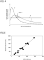
- Fig. 4 collectively shows the "curve a" (first curve) indicating the yield shear stress in the depth direction of the raceway surface of the material forming the rolling bearing in a state before the machining is performed on the raceway surface, a “curve c" (second curve) indicating static shear stress in the depth direction of the raceway surface when the machining is performed under a predetermined condition, that is, in a state in which the machining is performed on the raceway surface, and the “curve b" (third curve) indicating the static shear stress in the depth direction of the raceway surface when the predetermined static load is applied, that is, in a state in which the rolling elements are in contact with the raceway surface and the static load is applied.
- indentation resistance of the raceway ring obtained from machining conditions can be predicted based on an "area A" (plastic deformation index) of a region (hatched portion in the drawing) surrounded by exceeding the curve a (first curve) and the curve c (second curve) and falling below the curve b (third curve).
- area A plastic deformation index
- Each curve can be obtained by the following calculation.
- the static shear stress ⁇ st generated inside the raceway ring is expressed by the following equation (1), in which ⁇ x (unit MPa) is a vertical stress generated with respect to the tangential direction of the rolling element and ⁇ z (unit MPa) is a vertical stress generated with respect to a normal direction at a contact point between the raceway ring and the rolling element, and can be calculated using a known elastic theoretical solution.
- the vertical stresses ⁇ x and ⁇ z can be calculated using, for example, an elastic theoretical solution of Hanson ( Hanson, M.T. and Johnson, T., "The Elastic Field for Spherical HertzianContact of Isotropic Bodies Revisited: Some Alternative Expressions", Transactions of the ASME, Journal of Tribology, Vol. 115 (1993), pp.327-332 ).
- Hanson, M.T. and Johnson, T. "The Elastic Field for Spherical HertzianContact of Isotropic Bodies Revisited: Some Alternative Expressions", Transactions of the ASME, Journal of Tribology, Vol. 115 (1993), pp.327-332 ).
- a contact surface radius a, and a Poisson's ratio v, ⁇ x and ⁇ z are expressed by the following equations (2) to (7).
- the maximum contact surface pressure q max of the Hertz contact and the contact surface radius a can be calculated with reference to, for example, "Ball Bearing Design Calculation Guide” (Junzou Okamoto, 2011).
- the vertical stresses ⁇ x and ⁇ z can be calculated by using, for example, an elastic theoretical solution of Smith ( Smith, J.O., Liu, C.K.
- each curve is calculated based on the above equations, and a difference among the curve a, the curve b, and the curve c at the same depth from the surface is integrated in the depth direction from the surface, so that the area A can be obtained.
- the calculation can be approximately performed by using a sectional measurement method. That is, the rolling element is divided into a plurality of minute sections ⁇ Z in the normal direction of the rolling element with reference to the contact point between the raceway ring and the rolling element, and areas of these minute sections may be added. For more accurate calculation, it is desirable to reduce the minute section ⁇ Z, and 0.01 mm is appropriate. Even when the minute section ⁇ Z is smaller than 0.01 mm, a difference among the calculated areas A is negligibly small.
- the present invention relates to a method for measuring an indentation formation amount and a method for predicting the indentation formation amount that are applied to a case in which a metal is subjected to machining by a theory of the Hertz contact such as roller burnishing, and a deformation theory such as a rolling bearing is caused by the Hertz contact, and the present invention is intended to select machining conditions for controlling the indentation formation amount and the bearing material quality after heat treatment.
- Example 1 A steel ball was pressed against a flat plate-shaped test piece simulating the raceway ring of the rolling bearing, and a depth of an indentation generated on a surface of the test piece was measured.
- Each test piece was made of bearing steel (SUJ2 steel) and was subjected to quenching and tempering.
- quenching at 840°C and tempering at 180°C were performed, and in Example 2, quenching at 840°C and tempering at 300°C were performed. After flat finishing was performed, burnishing was performed in Examples 1 and 2.
- Comparative Example 1 the quenching at 840°C and the tempering at 180°C were performed, and in Comparative Example 2, the quenching at 840°C and the tempering at 300°C were performed.
- the burnishing conditions were as follows: a tip shape of a burnishing tool was ⁇ 3 mm, a slip rate was 100%, a peripheral speed was 100m/min, a tool feed speed was 0.05 mm/rev, and a tool pushing amount was 0.3 mm.
- a filtered working fluid was used, and the maximum contact surface pressure was calculated on an assumption that only elastic deformation occurred, and a burnishing load was set to 9.2 GPa.
- Fig. 5 is a graph showing a relationship between the area A and the indentation depth of the raceway ring. As shown in Fig. 5 , a good correlation was observed between the calculated area A and the measured indentation depth.
- the indentation depth can be predicted as long as the area A can be calculated, it is not necessary to perform a test for evaluating indentation resistance every time the test piece is prepared, and indentation resistance of the bearing raceway ring after being subjected to the machining can be predicted, so that a bearing having excellent indentation resistance can be provided.
- the area A can be obtained, so that the indentation resistance of the raceway ring has any size, the second curve can be obtained so as to form the area A, and then the machining conditions can be determined so as to form the second curve.
- the area A can be obtained, so that the indentation resistance of the raceway ring has any size, the first curve can be obtained, so as to form the area A, and then, the bearing material quality after the heat treatment can be determined so as to form the first curve.
- a bearing having excellent indentation resistance can be manufactured by a bearing manufacturing method including at least one step among the above-described method for predicting indentation resistance of a rolling bearing, the method for selecting machining conditions, and the method for selecting bearing material quality.
- Example 1 Comparative Example 1 Example 2 Comparative Example 2 Surface Pressure (Gpa) Depth (nm) Area A (Mpa ⁇ mm) Depth (nm) Area A (Mpa ⁇ mm) Depth (nm) Area A (Mpa ⁇ mm) Depth (nm) Area A (Mpa ⁇ mm) 5.0 132 37 558 85 269 58 892 134 5.5 332 82 935 143 874 114 1565 203 6.0 765 144 1460 215 1500 188 2280 288
- a type and configuration of a rolling bearing are not limited, and for example, the radial ball bearing shown in Fig. 1 can be shown.
- the outer ring raceway surface 2 and the inner ring raceway surface 4 are subjected to burnishing as the maching.
- a tip of a burnishing tool that has a spherical shape and the raceway surface come into contact with each other, and thus, it can be considered that the burnishing tool and the raceway surface come into the Hertz contact.
- a shear stress exceeding the yield shear stress of the material forming the rolling bearing is introduced in advance before the static load is applied.
- the amount of plastic deformation of the raceway surface can be estimated by the size of the "area S" of the region in which the static shear stress indicated by the curve b exceeds the yield shear stress of the material forming the rolling bearing indicated by the curve a. It can be said that the smaller the area S is, the less likely the plastic deformation occurs, and the less the indentation is formed on the raceway surface.
- indentation resistance of the raceway ring obtained from burnishing conditions can be predicted based on the "area A" (plastic deformation index) of the region (hatched portion in the drawing) surrounded by exceeding the curve a (first curve) and the curve c (second curve) and falling below the curve b (third curve).
- each curve is calculated based on the above equations, and a difference among the curve a, the curve b, and the curve c at the same depth from the surface is integrated in the depth direction from the surface, so that the area S or the area A can be obtained.
- the calculation can be approximately performed by using a sectional measurement method. That is, the rolling element is divided into a plurality of minute sections ⁇ Z in the normal direction of the rolling element with reference to the contact point between the raceway ring and the rolling element, and areas of these minute sections may be added. For more accurate calculation, it is desirable to reduce the minute section ⁇ Z, and 0.01 mm is appropriate. Even when the minute section ⁇ Z is smaller than 0.01 mm, a difference among the calculated areas A or areas S is negligibly small.
- a size of the burnishing ball that is, a radius of the burnishing ball, a material of the burnishing ball, and the burnishing load such that the burnishing indentation resistance index ⁇ is maximized at the xy coordinates.
- the material of the burnishing ball affects the burnishing conditions.
- a correlation is observed between a Young's modulus and indentation resistance of the burnishing ball, and the larger the Young's modulus of the material is, the larger the burnishing indentation resistance index ⁇ is.
- a material having a Young's modulus equal to or higher than a Young's modulus of iron (Young's modulus: 200 GPa)
- silicon nitride (Young's modulus: 320 GPa)
- cemented carbide such as tungsten carbide (Young's modulus: 550 GPa), diamond (Young's modulus: 786 GPa), or the like is more preferable.
- the indentation resistance of the bearing raceway ring that is subjected to the burnishing greatly differs. Therefore, as in the present invention, as long as the size and material of the burnishing ball and the burnishing load are determined to maximize the burnishing indentation resistance index ⁇ based on the correlation between the burnishing ball selection index B and the burnishing indentation resistance index ⁇ , it is possible to select optimum burnishing conditions for improving the indentation resistance of the bearing raceway ring without requiring preparing work and testing work of the test piece.
- the present invention according to the "second invention group” provides a bearing manufacturing method for a rolling bearing, including a burnishing step of performing burnishing on an inner ring raceway surface or an outer ring raceway surface under the optimum machining conditions selected as described above. Steps other than the burnishing step can be appropriately performed according to a manufacturing method in the related art.
- Target bearings are angular ball bearing inner rings, and a main bearing shape is shown in Table 2.
- a material of the target bearings is carbonitrided steel, and the rolling elements are ceramics.
- PCD is a pitch circle diameter of the rolling elements.
- the burnishing tools used in this verification are shown in Table 3.
- the material of the ball was any one of silicon nitride (Young's modulus: 320 GPa, Poisson's ratio: 0.26), tungsten carbide (Young's modulus: 550 GPa, Poisson's ratio: 0.22) which is a cemented carbide, and diamond (Young's modulus: 786 GPa, Poisson's ratio: 0.2).
- Table 4 summarizes the burnishing ball selection index B of each bearing for each burnishing tool.
- the burnishing ball selection index B In order to perform the burnishing on the raceway surface of the bearing, it is necessary that at least the burnishing ball selection index B ⁇ 1.
- the burnishing ball selection index B > 1 when the burnishing ball selection index B > 1, the ball at the tip of the burnishing tool cannot be inserted into the groove of the bearing raceway ring, and the desired burnishing cannot be performed. Therefore, in Table 4, "-" is shown when the burnishing ball selection index B > 1.
- Fig. 6 is a graph showing the xy coordinates in which the burnishing ball selection index B is "x" (horizontal axis) and the burnishing indentation resistance index ⁇ is "y" (vertical axis) when the burnishing tool, the material of the ball, and the burnishing load are changed. As shown in Fig.
- the correlation is observed between the burnishing indentation resistance index ⁇ and the burnishing ball selection index B, as the burnishing ball selection index B increases, the burnishing indentation resistance index ⁇ increases, and when the burnishing ball selection index B is equal to or greater than a certain value, the burnishing indentation resistance index ⁇ decreases.
- an optimum ball size of the burnishing tool exists in accordance with the groove radius of the bearing raceway ring depending on the verification based on the calculation.
- Fig. 7 shows the relationship between the burnishing ball selection index B and the burnishing indentation resistance index ⁇ when the burnishing load is changed in the verification using a burnishing tool 1 or 2 of which a material of a burnishing ball is cemented carbide. As shown in Fig. 7 , it was confirmed by the verification based on the calculation that the larger the burnishing load is, the further the indentation resistance of the bearing raceway ring is improved.
- Fig. 8 shows the relationship between the burnishing ball selection index B and the burnishing indentation resistance index ⁇ when the material of the burnishing ball is changed in the verification for the bearings 3 to 9 under the burnishing load of 2000N using the burnishing tool 2.
- the indentation resistance was improved in an order of iron, silicon nitride, cemented carbide (tungsten carbide), and diamond as the material of the burnishing ball, that is, the indentation resistance was improved as the Young's modulus was higher.
- the burnishing ball was formed of a material having a Young's modulus equal to or greater than 200 GPa of iron, the indentation resistance of the bearing raceway ring was improved.
- the indentation resistance of the bearing raceway ring that is subjected to the burnishing greatly differs. Therefore, as in the present invention, as long as the size and material of the burnishing ball and the burnishing load are determined to maximize the burnishing indentation resistance index ⁇ based on the correlation between the burnishing ball selection index B and the burnishing indentation resistance index ⁇ , it is possible to obtain optimum machining conditions for burnishing (tool selection) for improving the indentation resistance of the bearing raceway ring without requiring the preparing work and the testing work of the test piece.
Landscapes
- Engineering & Computer Science (AREA)
- General Engineering & Computer Science (AREA)
- Mechanical Engineering (AREA)
- Physics & Mathematics (AREA)
- General Physics & Mathematics (AREA)
- Manufacturing & Machinery (AREA)
- Analytical Chemistry (AREA)
- General Health & Medical Sciences (AREA)
- Immunology (AREA)
- Pathology (AREA)
- Biochemistry (AREA)
- Chemical & Material Sciences (AREA)
- Life Sciences & Earth Sciences (AREA)
- Health & Medical Sciences (AREA)
- Acoustics & Sound (AREA)
- Rolling Contact Bearings (AREA)
Abstract
Description
- The present invention relates to an indentation resistance measurement method, an indentation resistance prediction method for rolling bearings, a machining condition selection method, a bearing material quality selection method, a burnishing condition selection method and a bearing manufacturing method.
- In a rolling bearing, it is known that when an excessive load is received during rest, Hertz contact occurs between an outer ring raceway ring and an inner ring raceway ring of the rolling bearing and rolling elements, and permanent deformation (Brinell indentation) remains. When such an indentation exists, sound and vibration characteristics are affected during use of the rolling bearing. For example, in a rolling bearing for use in high-speed rotation such as a machine tool, even a minute indentation of about 1 µm causes a serious problem of abnormal noise and vibration. Therefore, when the rolling bearing is designed, a static limit load (basic static rated load) is determined by a contact stress, and in JISB 1519 (2009), for example, a contact stress of a radial ball bearing other than a thrust ball bearing and a self-aligning ball bearing is determined to be 4.2 GPa.
- In addition, in order to reduce a size of the rolling bearing, which is a background of reduction in fuel consumption of an automobile or the like, plastic deformation resistance that can withstand an excessive load is required. In related art, in order to improve plastic deformation resistance of a rolling bearing, a balance between hardness of an outer ring raceway ring and an inner ring raceway ring of the rolling bearing and an amount of retained austenite is important. An attempt has been made to improve permanent deformation resistance by increasing the hardness of the raceway rings of the rolling bearing or reducing the retained austenite, which is a soft structure of steel, thereby improving indentation resistance.
- For example,
Patent Literature 1 discloses a technique in which a high carbon chromium bearing steel is subjected to carbonitriding treatment and tempering. Further,Patent Literature 2 discloses a technique in which raceway surfaces of inner and outer rings of a bearing is subjected to sub-zero treatment. - However, when attempting to improve the indentation resistance only by such heat treatment and component adjustment, special heat treatment such as the carbonitriding treatment and the sub-zero treatment takes a long time, and additionally requires steps therefor, resulting in an increase in manufacturing cost.
- On the other hand, an indentation is formed as plastic deformation of the raceway surface, and can be considered as a simple yield phenomenon of a material. There are various methods for strengthening materials, and there are methods of work hardening in addition to the heat treatment and the component adjustment. The inventors have found that the indentation resistance can be further improved by performing machining on a material, such as quenched steel, that is hardened to a maximum extent by the heat treatment. There are various methods of machining, such as burnishing and shot peening, and these methods are also industrially implemented. In particular, the burnishing can prevent deterioration of surface properties caused by the shot peening or the like, and can prevent a removal at the time of finishing to be performed as necessary in a subsequent step.
-
- Patent Literature 1:
JP-A-2015-200351 - Patent Literature 2:
JP-A-2000-274440 - However, in any case, it is difficult to predict what kind of machining is performed on what kind of bearing material to appropriately improve the indentation resistance of the rolling bearing, and therefore, it is necessary to perform many prototypes, evaluations, and studies. For this reason, it is necessary to prepare test pieces in which treatment conditions, machining conditions, alloy composition, and the like are variously changed and evaluate the test pieces each time, which requires cost and time.
- The present invention has been made in view of the above problems, and an object of the present invention is to provide a method for measuring indentation resistance of a raceway ring of each of an outer ring and an inner ring when an outer ring raceway surface and an inner ring raceway surface are cured by machining without requiring the preparing work and the testing work of a test piece, a method for predicting indentation resistance of a rolling bearing, further to provide a method capable of selecting machining conditions and selecting bearing material quality after heat treatment, and a bearing manufacturing method.
- Further, an object of the present invention is to provide a method for selecting optimum burnishing conditions for improving indentation resistance and a bearing manufacturing method, when a raceway surface of a bearing raceway ring such as an outer ring raceway surface or an inner ring raceway surface is cured by burnishing in verification based on calculation without requiring the preparing work and the testing work of the test piece.
- An indentation in a rolling bearing is formed as plastic deformation caused by surface contact between rolling elements and a raceway ring. A stress that causes this plastic deformation is explained by a theory of Hertz contact. On the other hand, when a load exceeding a yield stress is applied to a metal, the plastic deformation occurs, and in order to continue the plastic deformation, a larger load is required, and a phenomenon referred to as "work hardening" occurs. In addition, when a work-hardened metal is once unloaded, the work-hardened metal is not deformed unless a load equal to or more than the yield stress is applied. When these phenomena are combined, if machining is performed in advance in accordance with a stress field of the Hertz contact generated between the rolling elements and the raceway ring, a region deformed by the contact between the rolling elements and the raceway ring will not be deformed a range thereof, and a difference therebetween will contribute to the formation of indentations.
- That is, the deformation of the material can be explained based on the theory of Hertz contact, and if a calibration curve is experimentally created, a formation amount of the indentation generated by the added machining can be predicted only by geometric calculation. For example, when burnishing is performed as the machining, optimum machining conditions can be selected in consideration of a size of a burnishing ball mounted on a tip of a burnishing tool, a material forming the burnishing ball, a burnishing load, and the like at the time of prediction.
- The present invention is based on such findings, and provides a method for measuring indentation resistance shown in (1) below in order to solve the above problems.
- (1) A method for measuring indentation resistance of a rolling bearing in which a plurality of rolling elements are freely rollably held between raceway rings each having a raceway surface subjected to machining, the method includes:
- obtaining a first curve indicating a yield shear stress in a depth direction of the raceway surface of a material forming the rolling bearing in a state before the raceway surface is subjected to the machining,
- a second curve indicating a static shear stress in the depth direction of the raceway surface in a state in which the raceway surface is subjected to the machining, and
- a third curve indicating a static shear stress in the depth direction of the raceway surface in a state in which the rolling elements are in contact with the raceway surface and a static load is applied to the raceway surface; and
- obtaining a correlation between an area A and an indentation depth of the raceway ring by defining a region surrounded by exceeding the first curve and the second curve and falling below the third curve as the area A.
- obtaining a first curve indicating a yield shear stress in a depth direction of the raceway surface of a material forming the rolling bearing in a state before the raceway surface is subjected to the machining,
- (2) A method for predicting indentation resistance of a rolling bearing, includes: predicting indentation resistance of the raceway ring based on the method for measuring indentation resistance according to (1).
- (3) A method for selecting machining conditions using the method for predicting indentation resistance of a rolling bearing according to (2), includes:
based on the correlation between the area A and the indentation depth of the raceway ring, obtaining the area A, so that the indentation resistance of the raceway ring has any size, obtaining the second curve so as to form the area A, and then determining machining conditions so as to form the second curve. - (4) A method for selecting bearing material quality using the method for predicting indentation resistance of a rolling bearing according to (2), includes:
based on the correlation between the area A and the indentation depth of the raceway ring, obtaining the area A, so that the indentation resistance of the raceway ring has any size, obtaining the first curve so as to form the area A, and then determining bearing material quality after heat treatment so as to form the first curve. - (5) A bearing manufacturing method includes at least one step of the method for predicting indentation resistance of a rolling bearing according to (2), the method for selecting machining conditions according to (3), and the method for selecting bearing material quality according to (4).
In the present specification, the invention according to (1) to (5) described above is referred to as a "first invention group".
In order to solve the above problems, the present invention provides a method for selecting burnishing conditions as described in (6) to (10) below. - (6) A method for selecting machining conditions of burnishing to be performed on a raceway surface of a bearing raceway ring, includes:
- obtaining a first curve indicating a yield shear stress in a depth direction of the raceway surface of a material forming the bearing raceway ring in a state before the raceway surface is subjected to the burnishing,
- a second curve indicating a static shear stress in the depth direction of the raceway surface in a state in which the raceway surface is subjected to the burnishing, and
- a third curve indicating a static shear stress in the depth direction of the raceway surface in a state in which rolling elements are in contact with the raceway surface and a static load is applied to the raceway surface; and
- when a region surrounded by exceeding the first curve and the second curve and falling below the third curve is defined as an area A, and
- obtaining a first curve indicating a yield shear stress in a depth direction of the raceway surface of a material forming the bearing raceway ring in a state before the raceway surface is subjected to the burnishing,
- (7) In the method for selecting burnishing conditions according to (6),
- the burnishing is performed by using a burnishing tool of which a tip is mounted with a burnishing ball, and
- when a value obtained by dividing a radius of the burnishing ball by a groove radius of the bearing raceway ring is defined as a burnishing ball selection index B, B ≤ 1.
- (8) In the method for selecting burnishing conditions according to (7),
a correlation is obtained between a burnishing indentation resistance index α, which is expressed by (the area S - the area A)/the area S", and the burnishing ball selection index B. - (9) In the method for selecting burnishing conditions according to (8),
based on the correlation between the burnishing indentation resistance index α and the burnishing ball selection index B, a size and a material of the burnishing ball and a burnishing load are determined, so that the burnishing indentation resistance index α is maximized. - (10) In the method for selecting burnishing conditions according to any one of (7) to (9),
a material having a Young's modulus of 200 GPa or more is selected as the burnishing ball.
The present invention further provides a bearing manufacturing method described in (11) below. - (11) A bearing manufacturing method includes a burnishing step using the burnishing conditions selected by the method for selecting burnishing conditions according to any one of (6) to (10).
- In the present specification, the invention according to (6) to (11) described above is referred to as a "second invention group".
- According to the present invention related to the above "first invention group", it is possible to measure indentation resistance of a bearing raceway ring, predict indentation resistance, select machining conditions, select bearing material quality after heat treatment, and manufacture a bearing excellent in indentation resistance without requiring preparing work and testing work of a test piece. Further, according to the present invention related to the "second invention group", it is possible to provide a method for selecting optimum machining conditions for improving indentation resistance and a bearing manufacturing method, when a raceway surface of a bearing raceway ring such as an outer ring raceway surface or an inner ring raceway surface is cured by burnishing in verification based on calculation without requiring the preparing work and the testing work of the test piece.
-
-
Fig. 1 is a partially cut-out perspective view showing a radial ball bearing as an example of a rolling bearing. -
Fig. 2 is a schematic diagram for illustrating static shear stress. -
Fig. 3 is a schematic diagram for illustrating a method for calculating an area S. -
Fig. 4 is a schematic diagram for illustrating a method for calculating an area A. -
Fig. 5 is a graph showing a relationship between the area A and an indentation depth of a raceway ring for illustrating the present invention according to a first invention group in a first embodiment. -
Fig. 6 is a graph showing a correlation between a burnishing ball selection index B and a burnishing indentation resistance index α when a burnishing tool, a material of the ball, and a burnishing load are changed, for illustrating the present invention according to a second invention group in a second embodiment. -
Fig. 7 is a graph showing a relationship between the burnishing ball selection index B and the burnishing indentation resistance index α when the burnishing load is changed, for illustrating the present invention according to the second invention group in the second embodiment. -
Fig. 8 is a graph showing a relationship between the burnishing ball selection index B and the burnishing indentation resistance index α when the material of the burnishing ball is changed, for illustrating the present invention according to the second invention group in the second embodiment. - Hereinafter, embodiments of the present invention will be described in detail. However, the present invention is not limited to the following embodiments, and can be appropriately modified and applied without changing the gist of the present invention.
In the following embodiments, an embodiment for describing the present invention according to the "first invention group" is referred to as a "first embodiment", and an embodiment for describing the present invention according to the "second invention group" is referred to as a "second embodiment". - First, the first embodiment will be described.
- In the present invention, a type and configuration of a rolling bearing are not limited, and for example, a radial ball bearing shown in
Fig. 1 can be shown. As shown inFig. 1 , theradial ball bearing 1 includes anouter ring 3 having an outerring raceway surface 2 on an inner peripheral surface thereof, aninner ring 5 having an innerring raceway surface 4 on an outer peripheral surface thereof, and a plurality ofballs 6 provided between the outerring raceway surface 2 and the innerring raceway surface 4 and serving as rolling elements. Theballs 6 are freely rollably held by acage 7 in a state in which theballs 6 are disposed at equal intervals in a circumferential direction. - The outer
ring raceway surface 2 and the innerring raceway surface 4 are subjected to machining. The machining is not limited, and burnishing or shot peening is preferable. - The burnishing is a machining method in which a device, which is a machining jig and is provided with a component having a spherical tip and high hardness, is pressed against the outer
ring raceway surface 2 and the innerring raceway surface 4, and theouter ring 3 and theinner ring 5 are rotated around axes thereof to cause a compressive stress to act on the outerring raceway surface 2 and the innerring raceway surface 4. In addition, the shot peening is a machining method in which a shot material having a high hardness and a substantially spherical shape is projected onto the outerring raceway surface 2 and the innerring raceway surface 4. By adjusting processing conditions such as a size, a material, and a projection speed of the substantially spherical shot material, quality can be adjusted to be equivalent to that of burnishing. - In the rolling bearing, when a static load is applied, a raceway ring may be plastically deformed due to contact with the rolling element, and an indentation may be generated in the raceway surface. A deformation amount due to the plastic deformation is considered to be caused by a relative relationship between a static yield shear stress of a material forming the rolling bearing and a static shear stress generated inside the raceway ring due to Hertz contact between the rolling elements and the raceway ring. As shown in
Fig. 2 , the static shear stress is a static shear stress (τst) acting on a contact point O between the raceway ring and the rolling element in directions of 45° with respect to a tangential direction of the rolling element. -
Fig. 3 shows a "curve a" indicating the yield shear stress in a depth direction of the raceway surface of the material forming the rolling bearing, and a "curve b" indicating the static shear stress in the depth direction of the raceway surface that is generated inside the raceway ring when a predetermined static load is applied. As shown inFig. 3 , a region (hatched portion in the drawing) in which the static shear stress indicated by the curve b exceeds the yield shear stress of the material forming the rolling bearing indicated by the curve a is formed, and the amount of plastic deformation of the raceway surface can be estimated by a size of an "area S". It can be said that the smaller the area S is, the less likely the plastic deformation occurs, and the less the indentation is formed on the raceway surface. InFig. 3 , the "curve a" is indicated by a simple straight line for the sake of convenience, but is actually a substantially straight curve. The same applies to the "curve a" inFig. 4 to be described below. - Similarly, when the raceway surface is subjected to the machining, the machining jig (the component having the spherical tip in the case of burnishing, and the shot material having the substantially spherical shape in the case of shot peening) and the raceway surface come into contact with each other, and thus, it can be considered that the machining jig and the raceway surface come into the Hertz contact. In addition, it can be considered that the static shear stress exceeding the yield shear stress of the material forming the rolling bearing is introduced in advance before the static load is applied.
-
Fig. 4 collectively shows the "curve a" (first curve) indicating the yield shear stress in the depth direction of the raceway surface of the material forming the rolling bearing in a state before the machining is performed on the raceway surface, a "curve c" (second curve) indicating static shear stress in the depth direction of the raceway surface when the machining is performed under a predetermined condition, that is, in a state in which the machining is performed on the raceway surface, and the "curve b" (third curve) indicating the static shear stress in the depth direction of the raceway surface when the predetermined static load is applied, that is, in a state in which the rolling elements are in contact with the raceway surface and the static load is applied. - In
Fig. 4 , indentation resistance of the raceway ring obtained from machining conditions can be predicted based on an "area A" (plastic deformation index) of a region (hatched portion in the drawing) surrounded by exceeding the curve a (first curve) and the curve c (second curve) and falling below the curve b (third curve). Each curve can be obtained by the following calculation. - The static shear stress τst generated inside the raceway ring is expressed by the following equation (1), in which σx (unit MPa) is a vertical stress generated with respect to the tangential direction of the rolling element and σz (unit MPa) is a vertical stress generated with respect to a normal direction at a contact point between the raceway ring and the rolling element, and can be calculated using a known elastic theoretical solution.
[Equation 1]
- When the vertical stresses σx and σz are in point contact, the vertical stresses σx and σz can be calculated using, for example, an elastic theoretical solution of Hanson (Hanson, M.T. and Johnson, T., "The Elastic Field for Spherical HertzianContact of Isotropic Bodies Revisited: Some Alternative Expressions", Transactions of the ASME, Journal of Tribology, Vol. 115 (1993), pp.327-332). By using a maximum contact surface pressure qmax of the Hertz contact, a contact surface radius a, and a Poisson's ratio v, σx and σz are expressed by the following equations (2) to (7).
[Equation 2]
[Equation 3]
[Equation 4]
[Equation 5]
[Equation 6]
[Equation 7]
- Here, x = r cos θ (r > 0), when x > 0, θ = 0, and when x < 0, θ = π. The maximum contact surface pressure qmax of the Hertz contact and the contact surface radius a can be calculated with reference to, for example, "Ball Bearing Design Calculation Guide" (Junzou Okamoto, 2011). When the vertical stresses σx and σz are in line contact, the vertical stresses σx and σz can be calculated by using, for example, an elastic theoretical solution of Smith (Smith, J.O., Liu, C.K. and Ill U., "Stress Due to Tangential and Normal Loads on an Elastic Solid With Application to Some Contact Stress Problems", Transaction of the ASME, Journal of Applied Mechanics, Vol.20 (1953), pp. 157-166), or a calculation formula of Tanaka (Chokkou Tanaka, "Calculation of Internal Stress of Elliptic Contact", TRANSACTIONS OF THE JAPAN SOCIETY OF MECHANICAL ENGINEERS Series C, Vol.61, No. 660 (2001), pp.265-269).
- A yield shear stress τy (unit MPa) of the material forming the rolling bearing is expressed by the following equation (8), in which a 0.2% proof stress is α0.2 and a Vickers hardness of the raceway ring is HV.
[Equation 8]
- Then, each curve is calculated based on the above equations, and a difference among the curve a, the curve b, and the curve c at the same depth from the surface is integrated in the depth direction from the surface, so that the area A can be obtained.
- In addition, in order to facilitate the calculation, the calculation can be approximately performed by using a sectional measurement method. That is, the rolling element is divided into a plurality of minute sections ΔZ in the normal direction of the rolling element with reference to the contact point between the raceway ring and the rolling element, and areas of these minute sections may be added. For more accurate calculation, it is desirable to reduce the minute section ΔZ, and 0.01 mm is appropriate. Even when the minute section ΔZ is smaller than 0.01 mm, a difference among the calculated areas A is negligibly small.
- The present invention relates to a method for measuring an indentation formation amount and a method for predicting the indentation formation amount that are applied to a case in which a metal is subjected to machining by a theory of the Hertz contact such as roller burnishing, and a deformation theory such as a rolling bearing is caused by the Hertz contact, and the present invention is intended to select machining conditions for controlling the indentation formation amount and the bearing material quality after heat treatment.
- Hereinafter, effects of the present invention according to the first invention group will be specifically described with reference to examples and comparative examples, but the present invention is not limited thereto. It was found that the area A obtained as described above has a high correlation with an indentation depth of the raceway surface as shown below.
- A steel ball was pressed against a flat plate-shaped test piece simulating the raceway ring of the rolling bearing, and a depth of an indentation generated on a surface of the test piece was measured. Each test piece was made of bearing steel (SUJ2 steel) and was subjected to quenching and tempering. In Example 1, quenching at 840°C and tempering at 180°C were performed, and in Example 2, quenching at 840°C and tempering at 300°C were performed. After flat finishing was performed, burnishing was performed in Examples 1 and 2. In Comparative Example 1, the quenching at 840°C and the tempering at 180°C were performed, and in Comparative Example 2, the quenching at 840°C and the tempering at 300°C were performed. Thereafter, in Comparative Examples 1 and 2, the burnishing was not performed, and only the flat finishing was performed. The burnishing conditions were as follows: a tip shape of a burnishing tool was ϕ3 mm, a slip rate was 100%, a peripheral speed was 100m/min, a tool feed speed was 0.05 mm/rev, and a tool pushing amount was 0.3 mm. At the time of machining, a filtered working fluid was used, and the maximum contact surface pressure was calculated on an assumption that only elastic deformation occurred, and a burnishing load was set to 9.2 GPa.
- In an indentation test, similarly to the test piece having a flat plate-shaped and simulating the raceway ring of the rolling bearing, a bearing steel was prepared, a steel ball in 3/8 inch subjected to quenching and tempering was used, a load was applied to the test piece so that the maximum contact surface pressure of the test piece became 5.0 GPa, 5.5 GPa, and 6.0 GPa, and then a depth of an indentation generated on the surface of the test piece was measured by using a three-dimensional surface texture measuring machine (CCI) manufactured by Taylor Hobson Ltd. Table 1 shows results of the indentation test and the calculation results of the area A. The results of Example 1 and Comparative Example 1 were compared, the results of Example 2 and Comparative Example 2 were compared, and it was confirmed that the indentation depth was reduced by being subjected to the burnishing.
-
Fig. 5 is a graph showing a relationship between the area A and the indentation depth of the raceway ring. As shown inFig. 5 , a good correlation was observed between the calculated area A and the measured indentation depth. - As described above, since the indentation depth can be predicted as long as the area A can be calculated, it is not necessary to perform a test for evaluating indentation resistance every time the test piece is prepared, and indentation resistance of the bearing raceway ring after being subjected to the machining can be predicted, so that a bearing having excellent indentation resistance can be provided.
- Further, based on the correlation between the area A and the indentation depth of the raceway ring, the area A can be obtained, so that the indentation resistance of the raceway ring has any size, the second curve can be obtained so as to form the area A, and then the machining conditions can be determined so as to form the second curve.
- Further, based on the correlation between the area A and the indentation depth of the raceway ring, the area A can be obtained, so that the indentation resistance of the raceway ring has any size, the first curve can be obtained, so as to form the area A, and then, the bearing material quality after the heat treatment can be determined so as to form the first curve.
- Furthermore, a bearing having excellent indentation resistance can be manufactured by a bearing manufacturing method including at least one step among the above-described method for predicting indentation resistance of a rolling bearing, the method for selecting machining conditions, and the method for selecting bearing material quality.
[Table 1] Example 1 Comparative Example 1 Example 2 Comparative Example 2 Surface Pressure (Gpa) Depth (nm) Area A (Mpa·mm) Depth (nm) Area A (Mpa·mm) Depth (nm) Area A (Mpa·mm) Depth (nm) Area A (Mpa·mm) 5.0 132 37 558 85 269 58 892 134 5.5 332 82 935 143 874 114 1565 203 6.0 765 144 1460 215 1500 188 2280 288 - Next, a second embodiment will be described.
- In the second embodiment, a type and configuration of a rolling bearing are not limited, and for example, the radial ball bearing shown in
Fig. 1 can be shown. The outerring raceway surface 2 and the innerring raceway surface 4 are subjected to burnishing as the maching. - When the raceway surface is subjected to the burnishing, a tip of a burnishing tool that has a spherical shape and the raceway surface come into contact with each other, and thus, it can be considered that the burnishing tool and the raceway surface come into the Hertz contact. In addition, it can be considered that a shear stress exceeding the yield shear stress of the material forming the rolling bearing is introduced in advance before the static load is applied.
- Therefore, as described with reference to
Fig. 3 , in the "curve a" indicating the yield shear stress in the depth direction of the raceway surface of the material forming the rolling bearing and the "curve b" indicating the static shear stress in the depth direction of the raceway surface generated inside the raceway ring when the predetermined static load is applied, the amount of plastic deformation of the raceway surface can be estimated by the size of the "area S" of the region in which the static shear stress indicated by the curve b exceeds the yield shear stress of the material forming the rolling bearing indicated by the curve a. It can be said that the smaller the area S is, the less likely the plastic deformation occurs, and the less the indentation is formed on the raceway surface. - Further, as described with reference to
Fig. 4 , indentation resistance of the raceway ring obtained from burnishing conditions can be predicted based on the "area A" (plastic deformation index) of the region (hatched portion in the drawing) surrounded by exceeding the curve a (first curve) and the curve c (second curve) and falling below the curve b (third curve). - Each curve can be obtained by the above equations (1) to (8).
- Then, each curve is calculated based on the above equations, and a difference among the curve a, the curve b, and the curve c at the same depth from the surface is integrated in the depth direction from the surface, so that the area S or the area A can be obtained.
- In addition, in order to facilitate the calculation, the calculation can be approximately performed by using a sectional measurement method. That is, the rolling element is divided into a plurality of minute sections ΔZ in the normal direction of the rolling element with reference to the contact point between the raceway ring and the rolling element, and areas of these minute sections may be added. For more accurate calculation, it is desirable to reduce the minute section ΔZ, and 0.01 mm is appropriate. Even when the minute section ΔZ is smaller than 0.01 mm, a difference among the calculated areas A or areas S is negligibly small.
- In order to improve the indentation resistance of the bearing raceway ring by burnishing, when the region surrounded by exceeding the curve a and the curve c and falling below the curve b is defined as the area A and the region surrounded by exceeding the curve a and falling below the curve b is defined as the area S, "area A < area S" is required. When the area A is equal to the area S, hardening due to the burnishing is insufficient, and this does not contribute to the improvement of the indentation resistance.
- In order to perform burnishing on the raceway surface of the bearing raceway ring, when a value obtained by dividing a radius of a burnishing ball, which is a burnishing tool, by a groove radius of the bearing raceway ring is defined as a burnishing ball selection index B, it is required that B ≤ 1. When B > 1, a ball at the tip of the burnishing tool cannot be inserted into a groove of the bearing raceway ring, and the desired burnishing cannot be performed.
- When a value obtained by dividing a value obtained by subtracting the area A from the area S by the area S, that is, "(area S - area A)/area S" is defined as a burnishing indentation resistance index α, a correlation is observed between the burnishing indentation resistance index α and the burnishing ball selection index B as shown in Examples described later. Then, as shown in
Figs. 6 to 8 to be described later, when an xy coordinates is adopted in which the burnishing ball selection index B is "x" (horizontal axis) and the burnishing indentation resistance index α is "y" (vertical axis), as the burnishing indentation resistance index α increases, the indentation resistance of the bearing raceway ring subjected to the burnishing is more effectively improved. - That is, it is preferable to determine a size of the burnishing ball, that is, a radius of the burnishing ball, a material of the burnishing ball, and the burnishing load such that the burnishing indentation resistance index α is maximized at the xy coordinates.
- Further, the material of the burnishing ball affects the burnishing conditions. Here, as shown in Examples to be described later, a correlation is observed between a Young's modulus and indentation resistance of the burnishing ball, and the larger the Young's modulus of the material is, the larger the burnishing indentation resistance index α is.
Specifically, it is preferable to select a material having a Young's modulus equal to or higher than a Young's modulus of iron (Young's modulus: 200 GPa), for example, silicon nitride (Young's modulus: 320 GPa) is preferable, a material referred to as cemented carbide such as tungsten carbide (Young's modulus: 550 GPa), diamond (Young's modulus: 786 GPa), or the like is more preferable. - As described above, depending on the ball size of the burnishing tool, the material forming the ball, and the burnishing load to be applied, the indentation resistance of the bearing raceway ring that is subjected to the burnishing greatly differs. Therefore, as in the present invention, as long as the size and material of the burnishing ball and the burnishing load are determined to maximize the burnishing indentation resistance index α based on the correlation between the burnishing ball selection index B and the burnishing indentation resistance index α, it is possible to select optimum burnishing conditions for improving the indentation resistance of the bearing raceway ring without requiring preparing work and testing work of the test piece.
- The present invention according to the "second invention group" provides a bearing manufacturing method for a rolling bearing, including a burnishing step of performing burnishing on an inner ring raceway surface or an outer ring raceway surface under the optimum machining conditions selected as described above. Steps other than the burnishing step can be appropriately performed according to a manufacturing method in the related art.
- An influence of the selection of the machining conditions for burnishing (tool selection) on the indentation resistance of the bearing raceway ring was verified based on calculation. Hereinafter, effects of the present invention according to the second invention group will be specifically described with reference to verification examples, but the present invention is not limited thereto.
- The indentation resistance when the burnishing was performed on various bearing raceway rings was verified. Target bearings are angular ball bearing inner rings, and a main bearing shape is shown in Table 2. A material of the target bearings is carbonitrided steel, and the rolling elements are ceramics. In Table 2, "PCD" is a pitch circle diameter of the rolling elements.
[Table 2] Bearing Number Inner Diameter of Inner Ring (mm) Groove Radius of Inner Ring (mm) Diameter of Rolling Element (mm) PCD (mm) Contact Angle (deg) Bearing 130 4.0 7.1 43 18 Bearing 240 4.4 7.9 54 18 Bearing 350 4.9 8.7 65 18 Bearing 460 5.7 10.3 78 18 Bearing 570 6.6 11.9 90 18 Bearing 680 7.5 13.5 103 18 Bearing 790 8.4 15.1 115 18 Bearing 8100 8.4 15.1 125 18 Bearing 9 110 10.6 19.1 140 18 - The burnishing tools used in this verification are shown in Table 3. For each tool, the size of the ball at the tip and the burnishing load that can be applied are different. The material of the ball was any one of silicon nitride (Young's modulus: 320 GPa, Poisson's ratio: 0.26), tungsten carbide (Young's modulus: 550 GPa, Poisson's ratio: 0.22) which is a cemented carbide, and diamond (Young's modulus: 786 GPa, Poisson's ratio: 0.2).
[Table 3] Burnishing Tool Number Ball Diameter (mm) Ball Material Burnishing Load (N) Tool 16.4 Silicon Nitride, Cemented Carbide, Diamond 500, 1000 Tool 29.5 Silicon Nitride, Cemented Carbide, Diamond 500, 1000, 2000 Tool 313.0 Silicon Nitride, Cemented Carbide, Diamond 500, 1000, 2000, 4000 Tool 419.0 Silicon Nitride, Cemented Carbide, Diamond 500, 1000, 2000, 4000, 9000 - Table 4 summarizes the burnishing ball selection index B of each bearing for each burnishing tool. In order to perform the burnishing on the raceway surface of the bearing, it is necessary that at least the burnishing ball selection index B ≤ 1. As described above, when the burnishing ball selection index B > 1, the ball at the tip of the burnishing tool cannot be inserted into the groove of the bearing raceway ring, and the desired burnishing cannot be performed. Therefore, in Table 4, "-" is shown when the burnishing ball selection index B > 1.

- Then, assuming that the rolling element was brought into contact with the raceway surface of the bearing and a static load of 4.6 GPa was applied as the maximum contact surface pressure, the curve a, the curve b, and the curve c were respectively obtained, and the area A and the area S were calculated. In Table 4, among combinations of the bearing and the tool in which"-" is not shown, "Area A < Area S" can be satisfied by appropriately selecting the material of the burnishing ball and the burnishing load, as will be described later.
- Subsequently, based on the area A and the area S, the burnishing indentation resistance index α, which is "(area S - area A)/area S", was calculated, and the correlation with the burnishing ball selection index B was examined.
Fig. 6 is a graph showing the xy coordinates in which the burnishing ball selection index B is "x" (horizontal axis) and the burnishing indentation resistance index α is "y" (vertical axis) when the burnishing tool, the material of the ball, and the burnishing load are changed. As shown inFig. 6 , the correlation is observed between the burnishing indentation resistance index α and the burnishing ball selection index B, as the burnishing ball selection index B increases, the burnishing indentation resistance index α increases, and when the burnishing ball selection index B is equal to or greater than a certain value, the burnishing indentation resistance index α decreases. As described above, it can be said that an optimum ball size of the burnishing tool exists in accordance with the groove radius of the bearing raceway ring depending on the verification based on the calculation. - Next,
Fig. 7 shows the relationship between the burnishing ball selection index B and the burnishing indentation resistance index α when the burnishing load is changed in the verification using aburnishing tool Fig. 7 , it was confirmed by the verification based on the calculation that the larger the burnishing load is, the further the indentation resistance of the bearing raceway ring is improved. Although the smaller the burnishing balls are, the better the indentation resistance of the bearing raceway ring is, since the maximum burnishing load that can be applied is limited in consideration of durability of the balls when the burnishing tool is actually used, it is necessary to select a desired burnishing tool from the optimum combinations of the ball size and the burnishing load. -
Fig. 8 shows the relationship between the burnishing ball selection index B and the burnishing indentation resistance index α when the material of the burnishing ball is changed in the verification for thebearings 3 to 9 under the burnishing load of 2000N using theburnishing tool 2. In this verification (verification based on the calculation), as the material of the burnishing ball, iron (Young's modulus: 200 GPa, Poisson's ratio: 0.28) was added in addition to silicon nitride (Young's modulus: 320 GPa, Poisson's ratio: 0.26), tungsten carbide (Young's modulus: 550 GPa, Poisson's ratio: 0.22) which is cemented carbide, and diamond (Young's modulus: 786 GPa, Poisson's ratio: 0.2) as described above, and the verification was performed. - As shown in
Fig. 8 , it was confirmed that the indentation resistance was improved in an order of iron, silicon nitride, cemented carbide (tungsten carbide), and diamond as the material of the burnishing ball, that is, the indentation resistance was improved as the Young's modulus was higher. In addition, in this verification, it was confirmed that as long as the burnishing ball was formed of a material having a Young's modulus equal to or greater than 200 GPa of iron, the indentation resistance of the bearing raceway ring was improved. - As described above, depending on the size of the burnishing ball, which is the burnishing tool, the material forming the ball, and the burnishing load to be applied, the indentation resistance of the bearing raceway ring that is subjected to the burnishing greatly differs. Therefore, as in the present invention, as long as the size and material of the burnishing ball and the burnishing load are determined to maximize the burnishing indentation resistance index α based on the correlation between the burnishing ball selection index B and the burnishing indentation resistance index α, it is possible to obtain optimum machining conditions for burnishing (tool selection) for improving the indentation resistance of the bearing raceway ring without requiring the preparing work and the testing work of the test piece.
- Although the embodiments are described above with reference to the drawings, it is needless to say that the present invention is not limited to such examples. It will be apparent to those skilled in the art that various changes and modifications may be conceived within the scope of the claims. It is also understood that the various changes and modifications belong to the technical scope of the present invention. Constituent elements in the embodiments described above may be combined freely within a range not departing from the spirit of the present invention.
- The present application is based on a Japanese patent application (
Japanese Patent Application No. 2020-080615) filed on April 30, 2020 Japanese Patent Application No. 2021-023516) filed on February 17, 2021 -
- 1 radial ball bearing
- 2 outer ring raceway surface
- 3 outer ring
- 4 inner ring raceway surface
- 5 inner ring
- 6 ball
- 7 cage
Claims (11)
- A method for measuring indentation resistance of a rolling bearing in which a plurality of rolling elements are freely rollably held between raceway rings each having a raceway surface subjected to machining, the method comprising:obtaining a first curve indicating a yield shear stress in a depth direction of the raceway surface of a material forming the rolling bearing in a state before the raceway surface is subjected to the machining,a second curve indicating a static shear stress in the depth direction of the raceway surface in a state in which the raceway surface is subjected to the machining, anda third curve indicating a static shear stress in the depth direction of the raceway surface in a state in which the rolling elements are in contact with the raceway surface and a static load is applied to the raceway surface; andobtaining a correlation between an area A and an indentation depth of the raceway ring by defining a region surrounded by exceeding the first curve and the second curve and falling below the third curve as the area A.
- A method for predicting indentation resistance of a rolling bearing, comprising:
predicting indentation resistance of the raceway ring based on the method for measuring indentation resistance according to claim 1. - A method for selecting machining conditions using the method for predicting indentation resistance of a rolling bearing according to claim 2, comprising:
based on the correlation between the area A and the indentation depth of the raceway ring, obtaining the area A, so that the indentation resistance of the raceway ring has any size, obtaining the second curve so as to form the area A, and then determining machining conditions so as to form the second curve. - A method for selecting bearing material quality using the method for predicting indentation resistance of a rolling bearing according to claim 2, comprising:
based on the correlation between the area A and the indentation depth of the raceway ring, obtaining the area A, so that the indentation resistance of the raceway ring has any size, obtaining the first curve so as to form the area A, and then determining bearing material quality after heat treatment so as to form the first curve. - A bearing manufacturing method comprising:
at least one step of the method for predicting indentation resistance of a rolling bearing according to claim 2, the method for selecting machining conditions according to claim 3, and the method for selecting bearing material quality according to claim 4. - A method for selecting machining conditions of burnishing to be performed on a raceway surface of a bearing raceway ring, comprising:obtaining a first curve indicating a yield shear stress in a depth direction of the raceway surface of a material forming the bearing raceway ring in a state before the raceway surface is subjected to the burnishing,a second curve indicating a static shear stress in the depth direction of the raceway surface in a state in which the raceway surface is subjected to the burnishing, anda third curve indicating a static shear stress in the depth direction of the raceway surface in a state in which rolling elements are in contact with the raceway surface and a static load is applied to the raceway surface; andwhen a region surrounded by exceeding the first curve and the second curve and falling below the third curve is defined as an area A, and a region surrounded by exceeding the first curve and falling below the third curve is defined as an area S, selecting machining conditions satisfying the area A < the area S.
- The method for selecting burnishing conditions according to claim 6,wherein the burnishing is performed by using a burnishing tool of which a tip is mounted with a burnishing ball, andwhen a value obtained by dividing a radius of the burnishing ball by a groove radius of the bearing raceway ring is defined as a burnishing ball selection index B, B ≤ 1.
- The method for selecting burnishing conditions according to claim 7,
wherein a correlation is obtained between a burnishing indentation resistance index α, which is expressed by (the area S - the area A)/the area S", and the burnishing ball selection index B. - The method for selecting burnishing conditions according to claim 8,
wherein based on the correlation between the burnishing indentation resistance index α and the burnishing ball selection index B, a size and a material of the burnishing ball and a burnishing load are determined, so that the burnishing indentation resistance index α is maximized. - The method for selecting burnishing conditions according to any one of claims 7 to 9,
wherein a material having a Young's modulus of 200 GPa or more is selected as the burnishing ball. - A bearing manufacturing method comprising:
a burnishing step using the burnishing conditions selected by the method for selecting burnishing conditions according to any one of claims 6 to 10.
Applications Claiming Priority (3)
| Application Number | Priority Date | Filing Date | Title |
|---|---|---|---|
| JP2020080615 | 2020-04-30 | ||
| JP2021023516 | 2021-02-17 | ||
| PCT/JP2021/014752 WO2021220749A1 (en) | 2020-04-30 | 2021-04-07 | Indentation resistance measurement method, indentation resistance prediction method for rolling bearings, machining condition selection method, bearing material quality selection method, burnishing condition selection method, and bearing manufacturing method |
Publications (3)
| Publication Number | Publication Date |
|---|---|
| EP4145103A1 true EP4145103A1 (en) | 2023-03-08 |
| EP4145103A4 EP4145103A4 (en) | 2023-11-01 |
| EP4145103B1 EP4145103B1 (en) | 2024-12-11 |
Family
ID=78373498
Family Applications (1)
| Application Number | Title | Priority Date | Filing Date |
|---|---|---|---|
| EP21795291.0A Active EP4145103B1 (en) | 2020-04-30 | 2021-04-07 | Indentation resistance measurement method, indentation resistance prediction method for rolling bearings, machining condition selection method, bearing material quality selection method, burnishing condition selection method, and bearing manufacturing method |
Country Status (6)
| Country | Link |
|---|---|
| US (1) | US11965556B2 (en) |
| EP (1) | EP4145103B1 (en) |
| JP (1) | JP6969712B1 (en) |
| KR (1) | KR102935862B1 (en) |
| CN (1) | CN115398197B (en) |
| WO (1) | WO2021220749A1 (en) |
Family Cites Families (21)
| Publication number | Priority date | Publication date | Assignee | Title |
|---|---|---|---|---|
| US5999887A (en) * | 1997-02-26 | 1999-12-07 | Massachusetts Institute Of Technology | Method and apparatus for determination of mechanical properties of functionally-graded materials |
| JP3277893B2 (en) * | 1998-07-24 | 2002-04-22 | 松下電工株式会社 | Manufacturing method of laminated board |
| JP2000274440A (en) | 1999-03-23 | 2000-10-03 | Nsk Ltd | Rolling bearing for air conditioner motor |
| JP2004339575A (en) | 2003-05-16 | 2004-12-02 | Nsk Ltd | Method of manufacturing rolling device parts |
| US7149634B2 (en) * | 2004-01-14 | 2006-12-12 | The Hong Kong Polytechnic University | Method of determining elastic modulus |
| JP4631578B2 (en) * | 2005-07-26 | 2011-02-16 | 株式会社デンソー | Design method for grasping the damage form of rolling bearings |
| CN101400809B (en) * | 2006-05-19 | 2011-11-09 | 日本精工株式会社 | Rolling device |
| WO2011115101A1 (en) * | 2010-03-16 | 2011-09-22 | Ntn株式会社 | Method of assessing rolling contact metallic material shear stress fatigue values, and method and device using same that estimate fatigue limit surface pressure |
| JP2011208751A (en) * | 2010-03-30 | 2011-10-20 | Ntn Corp | Rolling bearing, method for manufacturing roller, and roller machining device |
| JP5895493B2 (en) * | 2011-01-21 | 2016-03-30 | 日本精工株式会社 | Rolling bearing manufacturing method, induction heat treatment apparatus |
| CN103748449A (en) * | 2011-04-04 | 2014-04-23 | Skf公司 | Method for fatigue assessment of rolling bearing |
| JP5908356B2 (en) * | 2012-07-12 | 2016-04-26 | Ntn株式会社 | Life estimation apparatus and life estimation method for rolling bearing |
| WO2014069068A1 (en) * | 2012-10-29 | 2014-05-08 | 日本精工株式会社 | Rolling bearing |
| JP2015200351A (en) | 2014-04-07 | 2015-11-12 | 日本精工株式会社 | Ball bearing |
| JP2016114234A (en) * | 2014-12-18 | 2016-06-23 | 日本精工株式会社 | Method for evaluating anti-indentation characteristic of bearing ring |
| JP2016148393A (en) * | 2015-02-12 | 2016-08-18 | 日本精工株式会社 | Evaluation method of pressure resistance and acoustic deterioration of rolling bearings and rolling bearings |
| DE102015207779A1 (en) * | 2015-04-28 | 2016-11-03 | Schaeffler Technologies AG & Co. KG | Method for producing rolling bearing rings and roller bearings |
| JP6817086B2 (en) * | 2017-01-25 | 2021-01-20 | Ntn株式会社 | Manufacturing method of rolling parts |
| JP2020080615A (en) | 2018-11-13 | 2020-05-28 | 中国電力株式会社 | Clip for indirect live wire construction |
| CN109681532B (en) * | 2019-01-07 | 2020-10-02 | 广州大学 | A composite machining method for the inner ring of a roller bearing |
| JP6935104B2 (en) | 2019-08-02 | 2021-09-15 | 株式会社オリンピア | Pachinko machine |
-
2021
- 2021-04-07 JP JP2021534918A patent/JP6969712B1/en active Active
- 2021-04-07 EP EP21795291.0A patent/EP4145103B1/en active Active
- 2021-04-07 WO PCT/JP2021/014752 patent/WO2021220749A1/en not_active Ceased
- 2021-04-07 KR KR1020227032968A patent/KR102935862B1/en active Active
- 2021-04-07 US US17/631,178 patent/US11965556B2/en active Active
- 2021-04-07 CN CN202180024632.XA patent/CN115398197B/en active Active
Also Published As
| Publication number | Publication date |
|---|---|
| JPWO2021220749A1 (en) | 2021-11-04 |
| US20220268316A1 (en) | 2022-08-25 |
| KR20230004457A (en) | 2023-01-06 |
| EP4145103B1 (en) | 2024-12-11 |
| CN115398197B (en) | 2025-09-16 |
| KR102935862B1 (en) | 2026-03-05 |
| WO2021220749A1 (en) | 2021-11-04 |
| JP6969712B1 (en) | 2021-11-24 |
| US11965556B2 (en) | 2024-04-23 |
| CN115398197A (en) | 2022-11-25 |
| EP4145103A4 (en) | 2023-11-01 |
Similar Documents
| Publication | Publication Date | Title |
|---|---|---|
| EP3009698B1 (en) | Tapered roller bearing | |
| EP2910657B1 (en) | Bearing element, rolling bearing and process for producing bearing element | |
| EP2789705B1 (en) | Machine part, rolling bearing, conical roller bearing and method for manufacturing machine part | |
| JP5196393B2 (en) | Rolling member, rolling bearing, and rolling member manufacturing method | |
| EP3315619A1 (en) | Method for producing bearing part | |
| EP3591089A1 (en) | Bearing component, rolling bearing, and bearing component manufacturing method | |
| JP2011208751A (en) | Rolling bearing, method for manufacturing roller, and roller machining device | |
| JPH1161337A (en) | Rolling member and rolling device provided with the same | |
| EP4145103B1 (en) | Indentation resistance measurement method, indentation resistance prediction method for rolling bearings, machining condition selection method, bearing material quality selection method, burnishing condition selection method, and bearing manufacturing method | |
| EP3779221B1 (en) | Intermediary race member of rolling bearing, race, rolling bearing and production method therefor | |
| JP2005282854A (en) | Rolling bearing | |
| JP2009236145A (en) | Steelmaking equipment bearing component, steelmaking rolling bearing, and steelmaking equipment | |
| JP7625981B2 (en) | Manufacturing method of rolling bearing | |
| EP4219968B1 (en) | Angular ball bearing | |
| CN111373168B (en) | Rolling member, bearing, and method for manufacturing same | |
| JP5779118B2 (en) | Rolling contact parts, rolling bearings, universal joints, and manufacturing methods thereof | |
| JP4949234B2 (en) | Rolling exercise apparatus and manufacturing method thereof | |
| JP2008151236A (en) | Rolling bearing | |
| JP7724609B2 (en) | Bearing parts | |
| US20240376933A1 (en) | Transmission shaft and bearing device using same | |
| JP2007186760A (en) | Method of manufacturing bearing ring for rolling bearing and rolling bearing | |
| Sağır et al. | The effects of hard turning and deep rolling on surface integrity and fatigue life of deep groove ball bearings | |
| WO2006001149A1 (en) | Rolling bearing | |
| US10337559B2 (en) | Ball bearing and methods of production of ball bearing | |
| WO2023037846A1 (en) | Machine component |
Legal Events
| Date | Code | Title | Description |
|---|---|---|---|
| STAA | Information on the status of an ep patent application or granted ep patent |
Free format text: STATUS: THE INTERNATIONAL PUBLICATION HAS BEEN MADE |
|
| PUAI | Public reference made under article 153(3) epc to a published international application that has entered the european phase |
Free format text: ORIGINAL CODE: 0009012 |
|
| STAA | Information on the status of an ep patent application or granted ep patent |
Free format text: STATUS: REQUEST FOR EXAMINATION WAS MADE |
|
| 17P | Request for examination filed |
Effective date: 20220926 |
|
| AK | Designated contracting states |
Kind code of ref document: A1 Designated state(s): AL AT BE BG CH CY CZ DE DK EE ES FI FR GB GR HR HU IE IS IT LI LT LU LV MC MK MT NL NO PL PT RO RS SE SI SK SM TR |
|
| DAV | Request for validation of the european patent (deleted) | ||
| DAX | Request for extension of the european patent (deleted) | ||
| A4 | Supplementary search report drawn up and despatched |
Effective date: 20231004 |
|
| RIC1 | Information provided on ipc code assigned before grant |
Ipc: F16C 33/64 20060101ALI20230927BHEP Ipc: F16C 33/58 20060101ALI20230927BHEP Ipc: F16C 19/06 20060101ALI20230927BHEP Ipc: G01M 13/04 20190101AFI20230927BHEP |
|
| GRAP | Despatch of communication of intention to grant a patent |
Free format text: ORIGINAL CODE: EPIDOSNIGR1 |
|
| STAA | Information on the status of an ep patent application or granted ep patent |
Free format text: STATUS: GRANT OF PATENT IS INTENDED |
|
| INTG | Intention to grant announced |
Effective date: 20240716 |
|
| GRAS | Grant fee paid |
Free format text: ORIGINAL CODE: EPIDOSNIGR3 |
|
| GRAA | (expected) grant |
Free format text: ORIGINAL CODE: 0009210 |
|
| STAA | Information on the status of an ep patent application or granted ep patent |
Free format text: STATUS: THE PATENT HAS BEEN GRANTED |
|
| AK | Designated contracting states |
Kind code of ref document: B1 Designated state(s): AL AT BE BG CH CY CZ DE DK EE ES FI FR GB GR HR HU IE IS IT LI LT LU LV MC MK MT NL NO PL PT RO RS SE SI SK SM TR |
|
| REG | Reference to a national code |
Ref country code: GB Ref legal event code: FG4D |
|
| REG | Reference to a national code |
Ref country code: CH Ref legal event code: EP |
|
| REG | Reference to a national code |
Ref country code: IE Ref legal event code: FG4D |
|
| REG | Reference to a national code |
Ref country code: DE Ref legal event code: R096 Ref document number: 602021023338 Country of ref document: DE |
|
| REG | Reference to a national code |
Ref country code: LT Ref legal event code: MG9D |
|
| PG25 | Lapsed in a contracting state [announced via postgrant information from national office to epo] |
Ref country code: HR Free format text: LAPSE BECAUSE OF FAILURE TO SUBMIT A TRANSLATION OF THE DESCRIPTION OR TO PAY THE FEE WITHIN THE PRESCRIBED TIME-LIMIT Effective date: 20241211 |
|
| PG25 | Lapsed in a contracting state [announced via postgrant information from national office to epo] |
Ref country code: FI Free format text: LAPSE BECAUSE OF FAILURE TO SUBMIT A TRANSLATION OF THE DESCRIPTION OR TO PAY THE FEE WITHIN THE PRESCRIBED TIME-LIMIT Effective date: 20241211 |
|
| PG25 | Lapsed in a contracting state [announced via postgrant information from national office to epo] |
Ref country code: BG Free format text: LAPSE BECAUSE OF FAILURE TO SUBMIT A TRANSLATION OF THE DESCRIPTION OR TO PAY THE FEE WITHIN THE PRESCRIBED TIME-LIMIT Effective date: 20241211 |
|
| REG | Reference to a national code |
Ref country code: NL Ref legal event code: MP Effective date: 20241211 |
|
| PG25 | Lapsed in a contracting state [announced via postgrant information from national office to epo] |
Ref country code: ES Free format text: LAPSE BECAUSE OF FAILURE TO SUBMIT A TRANSLATION OF THE DESCRIPTION OR TO PAY THE FEE WITHIN THE PRESCRIBED TIME-LIMIT Effective date: 20241211 |
|
| PG25 | Lapsed in a contracting state [announced via postgrant information from national office to epo] |
Ref country code: NO Free format text: LAPSE BECAUSE OF FAILURE TO SUBMIT A TRANSLATION OF THE DESCRIPTION OR TO PAY THE FEE WITHIN THE PRESCRIBED TIME-LIMIT Effective date: 20250311 |
|
| PG25 | Lapsed in a contracting state [announced via postgrant information from national office to epo] |
Ref country code: LV Free format text: LAPSE BECAUSE OF FAILURE TO SUBMIT A TRANSLATION OF THE DESCRIPTION OR TO PAY THE FEE WITHIN THE PRESCRIBED TIME-LIMIT Effective date: 20241211 Ref country code: GR Free format text: LAPSE BECAUSE OF FAILURE TO SUBMIT A TRANSLATION OF THE DESCRIPTION OR TO PAY THE FEE WITHIN THE PRESCRIBED TIME-LIMIT Effective date: 20250312 |
|
| PG25 | Lapsed in a contracting state [announced via postgrant information from national office to epo] |
Ref country code: RS Free format text: LAPSE BECAUSE OF FAILURE TO SUBMIT A TRANSLATION OF THE DESCRIPTION OR TO PAY THE FEE WITHIN THE PRESCRIBED TIME-LIMIT Effective date: 20250311 |
|
| PG25 | Lapsed in a contracting state [announced via postgrant information from national office to epo] |
Ref country code: NL Free format text: LAPSE BECAUSE OF FAILURE TO SUBMIT A TRANSLATION OF THE DESCRIPTION OR TO PAY THE FEE WITHIN THE PRESCRIBED TIME-LIMIT Effective date: 20241211 |
|
| REG | Reference to a national code |
Ref country code: AT Ref legal event code: MK05 Ref document number: 1750729 Country of ref document: AT Kind code of ref document: T Effective date: 20241211 |
|
| PG25 | Lapsed in a contracting state [announced via postgrant information from national office to epo] |
Ref country code: SM Free format text: LAPSE BECAUSE OF FAILURE TO SUBMIT A TRANSLATION OF THE DESCRIPTION OR TO PAY THE FEE WITHIN THE PRESCRIBED TIME-LIMIT Effective date: 20241211 |
|
| PG25 | Lapsed in a contracting state [announced via postgrant information from national office to epo] |
Ref country code: PL Free format text: LAPSE BECAUSE OF FAILURE TO SUBMIT A TRANSLATION OF THE DESCRIPTION OR TO PAY THE FEE WITHIN THE PRESCRIBED TIME-LIMIT Effective date: 20241211 |
|
| PGFP | Annual fee paid to national office [announced via postgrant information from national office to epo] |
Ref country code: DE Payment date: 20250305 Year of fee payment: 5 |
|
| PG25 | Lapsed in a contracting state [announced via postgrant information from national office to epo] |
Ref country code: IS Free format text: LAPSE BECAUSE OF FAILURE TO SUBMIT A TRANSLATION OF THE DESCRIPTION OR TO PAY THE FEE WITHIN THE PRESCRIBED TIME-LIMIT Effective date: 20250411 |
|
| PG25 | Lapsed in a contracting state [announced via postgrant information from national office to epo] |
Ref country code: PT Free format text: LAPSE BECAUSE OF FAILURE TO SUBMIT A TRANSLATION OF THE DESCRIPTION OR TO PAY THE FEE WITHIN THE PRESCRIBED TIME-LIMIT Effective date: 20250411 |
|
| PG25 | Lapsed in a contracting state [announced via postgrant information from national office to epo] |
Ref country code: EE Free format text: LAPSE BECAUSE OF FAILURE TO SUBMIT A TRANSLATION OF THE DESCRIPTION OR TO PAY THE FEE WITHIN THE PRESCRIBED TIME-LIMIT Effective date: 20241211 |
|
| PG25 | Lapsed in a contracting state [announced via postgrant information from national office to epo] |
Ref country code: AT Free format text: LAPSE BECAUSE OF FAILURE TO SUBMIT A TRANSLATION OF THE DESCRIPTION OR TO PAY THE FEE WITHIN THE PRESCRIBED TIME-LIMIT Effective date: 20241211 Ref country code: RO Free format text: LAPSE BECAUSE OF FAILURE TO SUBMIT A TRANSLATION OF THE DESCRIPTION OR TO PAY THE FEE WITHIN THE PRESCRIBED TIME-LIMIT Effective date: 20241211 |
|
| PG25 | Lapsed in a contracting state [announced via postgrant information from national office to epo] |
Ref country code: SK Free format text: LAPSE BECAUSE OF FAILURE TO SUBMIT A TRANSLATION OF THE DESCRIPTION OR TO PAY THE FEE WITHIN THE PRESCRIBED TIME-LIMIT Effective date: 20241211 |
|
| PG25 | Lapsed in a contracting state [announced via postgrant information from national office to epo] |
Ref country code: CZ Free format text: LAPSE BECAUSE OF FAILURE TO SUBMIT A TRANSLATION OF THE DESCRIPTION OR TO PAY THE FEE WITHIN THE PRESCRIBED TIME-LIMIT Effective date: 20241211 |
|
| PG25 | Lapsed in a contracting state [announced via postgrant information from national office to epo] |
Ref country code: IT Free format text: LAPSE BECAUSE OF FAILURE TO SUBMIT A TRANSLATION OF THE DESCRIPTION OR TO PAY THE FEE WITHIN THE PRESCRIBED TIME-LIMIT Effective date: 20241211 |
|
| PG25 | Lapsed in a contracting state [announced via postgrant information from national office to epo] |
Ref country code: SE Free format text: LAPSE BECAUSE OF FAILURE TO SUBMIT A TRANSLATION OF THE DESCRIPTION OR TO PAY THE FEE WITHIN THE PRESCRIBED TIME-LIMIT Effective date: 20241211 |
|
| REG | Reference to a national code |
Ref country code: DE Ref legal event code: R097 Ref document number: 602021023338 Country of ref document: DE |
|
| PG25 | Lapsed in a contracting state [announced via postgrant information from national office to epo] |
Ref country code: DK Free format text: LAPSE BECAUSE OF FAILURE TO SUBMIT A TRANSLATION OF THE DESCRIPTION OR TO PAY THE FEE WITHIN THE PRESCRIBED TIME-LIMIT Effective date: 20241211 |
|
| PLBE | No opposition filed within time limit |
Free format text: ORIGINAL CODE: 0009261 |
|
| STAA | Information on the status of an ep patent application or granted ep patent |
Free format text: STATUS: NO OPPOSITION FILED WITHIN TIME LIMIT |
|
| REG | Reference to a national code |
Ref country code: CH Ref legal event code: L10 Free format text: ST27 STATUS EVENT CODE: U-0-0-L10-L00 (AS PROVIDED BY THE NATIONAL OFFICE) Effective date: 20251022 |
|
| 26N | No opposition filed |
Effective date: 20250912 |
|
| REG | Reference to a national code |
Ref country code: CH Ref legal event code: H13 Free format text: ST27 STATUS EVENT CODE: U-0-0-H10-H13 (AS PROVIDED BY THE NATIONAL OFFICE) Effective date: 20251125 |
|
| PG25 | Lapsed in a contracting state [announced via postgrant information from national office to epo] |
Ref country code: LU Free format text: LAPSE BECAUSE OF NON-PAYMENT OF DUE FEES Effective date: 20250407 |
|
| PG25 | Lapsed in a contracting state [announced via postgrant information from national office to epo] |
Ref country code: MC Free format text: LAPSE BECAUSE OF FAILURE TO SUBMIT A TRANSLATION OF THE DESCRIPTION OR TO PAY THE FEE WITHIN THE PRESCRIBED TIME-LIMIT Effective date: 20241211 |
|
| GBPC | Gb: european patent ceased through non-payment of renewal fee |
Effective date: 20250407 |
|
| REG | Reference to a national code |
Ref country code: BE Ref legal event code: MM Effective date: 20250430 |
|
| PG25 | Lapsed in a contracting state [announced via postgrant information from national office to epo] |
Ref country code: GB Free format text: LAPSE BECAUSE OF NON-PAYMENT OF DUE FEES Effective date: 20250407 |
|
| PG25 | Lapsed in a contracting state [announced via postgrant information from national office to epo] |
Ref country code: BE Free format text: LAPSE BECAUSE OF NON-PAYMENT OF DUE FEES Effective date: 20250430 |
|
| PG25 | Lapsed in a contracting state [announced via postgrant information from national office to epo] |
Ref country code: CH Free format text: LAPSE BECAUSE OF NON-PAYMENT OF DUE FEES Effective date: 20250430 |
|
| PG25 | Lapsed in a contracting state [announced via postgrant information from national office to epo] |
Ref country code: IE Free format text: LAPSE BECAUSE OF NON-PAYMENT OF DUE FEES Effective date: 20250407 |
|
| PGFP | Annual fee paid to national office [announced via postgrant information from national office to epo] |
Ref country code: FR Payment date: 20260309 Year of fee payment: 6 |