EP4145050A1 - Control method for air conditioner - Google Patents
Control method for air conditioner Download PDFInfo
- Publication number
- EP4145050A1 EP4145050A1 EP21795743.0A EP21795743A EP4145050A1 EP 4145050 A1 EP4145050 A1 EP 4145050A1 EP 21795743 A EP21795743 A EP 21795743A EP 4145050 A1 EP4145050 A1 EP 4145050A1
- Authority
- EP
- European Patent Office
- Prior art keywords
- guide plate
- air guide
- temperature
- swing blade
- preset
- Prior art date
- Legal status (The legal status is an assumption and is not a legal conclusion. Google has not performed a legal analysis and makes no representation as to the accuracy of the status listed.)
- Granted
Links
Images



Classifications
-
- F—MECHANICAL ENGINEERING; LIGHTING; HEATING; WEAPONS; BLASTING
- F24—HEATING; RANGES; VENTILATING
- F24F—AIR-CONDITIONING; AIR-HUMIDIFICATION; VENTILATION; USE OF AIR CURRENTS FOR SCREENING
- F24F11/00—Control or safety arrangements
- F24F11/62—Control or safety arrangements characterised by the type of control or by internal processing, e.g. using fuzzy logic, adaptive control or estimation of values
- F24F11/63—Electronic processing
- F24F11/64—Electronic processing using pre-stored data
-
- F—MECHANICAL ENGINEERING; LIGHTING; HEATING; WEAPONS; BLASTING
- F24—HEATING; RANGES; VENTILATING
- F24F—AIR-CONDITIONING; AIR-HUMIDIFICATION; VENTILATION; USE OF AIR CURRENTS FOR SCREENING
- F24F1/00—Room units for air-conditioning, e.g. separate or self-contained units or units receiving primary air from a central station
- F24F1/0007—Indoor units, e.g. fan coil units
- F24F1/0011—Indoor units, e.g. fan coil units characterised by air outlets
- F24F1/0014—Indoor units, e.g. fan coil units characterised by air outlets having two or more outlet openings
-
- F—MECHANICAL ENGINEERING; LIGHTING; HEATING; WEAPONS; BLASTING
- F24—HEATING; RANGES; VENTILATING
- F24F—AIR-CONDITIONING; AIR-HUMIDIFICATION; VENTILATION; USE OF AIR CURRENTS FOR SCREENING
- F24F11/00—Control or safety arrangements
- F24F11/70—Control systems characterised by their outputs; Constructional details thereof
- F24F11/72—Control systems characterised by their outputs; Constructional details thereof for controlling the supply of treated air, e.g. its pressure
- F24F11/79—Control systems characterised by their outputs; Constructional details thereof for controlling the supply of treated air, e.g. its pressure for controlling the direction of the supplied air
-
- F—MECHANICAL ENGINEERING; LIGHTING; HEATING; WEAPONS; BLASTING
- F24—HEATING; RANGES; VENTILATING
- F24F—AIR-CONDITIONING; AIR-HUMIDIFICATION; VENTILATION; USE OF AIR CURRENTS FOR SCREENING
- F24F11/00—Control or safety arrangements
- F24F11/70—Control systems characterised by their outputs; Constructional details thereof
- F24F11/80—Control systems characterised by their outputs; Constructional details thereof for controlling the temperature of the supplied air
- F24F11/86—Control systems characterised by their outputs; Constructional details thereof for controlling the temperature of the supplied air by controlling compressors within refrigeration or heat pump circuits
-
- F—MECHANICAL ENGINEERING; LIGHTING; HEATING; WEAPONS; BLASTING
- F24—HEATING; RANGES; VENTILATING
- F24F—AIR-CONDITIONING; AIR-HUMIDIFICATION; VENTILATION; USE OF AIR CURRENTS FOR SCREENING
- F24F13/00—Details common to, or for air-conditioning, air-humidification, ventilation or use of air currents for screening
- F24F13/08—Air-flow control members, e.g. louvres, grilles, flaps or guide plates
- F24F13/10—Air-flow control members, e.g. louvres, grilles, flaps or guide plates movable, e.g. dampers
- F24F13/14—Air-flow control members, e.g. louvres, grilles, flaps or guide plates movable, e.g. dampers built up of tilting members, e.g. louvre
-
- F—MECHANICAL ENGINEERING; LIGHTING; HEATING; WEAPONS; BLASTING
- F24—HEATING; RANGES; VENTILATING
- F24F—AIR-CONDITIONING; AIR-HUMIDIFICATION; VENTILATION; USE OF AIR CURRENTS FOR SCREENING
- F24F2110/00—Control inputs relating to air properties
- F24F2110/10—Temperature
-
- F—MECHANICAL ENGINEERING; LIGHTING; HEATING; WEAPONS; BLASTING
- F24—HEATING; RANGES; VENTILATING
- F24F—AIR-CONDITIONING; AIR-HUMIDIFICATION; VENTILATION; USE OF AIR CURRENTS FOR SCREENING
- F24F2140/00—Control inputs relating to system states
-
- F—MECHANICAL ENGINEERING; LIGHTING; HEATING; WEAPONS; BLASTING
- F24—HEATING; RANGES; VENTILATING
- F24F—AIR-CONDITIONING; AIR-HUMIDIFICATION; VENTILATION; USE OF AIR CURRENTS FOR SCREENING
- F24F2221/00—Details or features not otherwise provided for
- F24F2221/54—Heating and cooling, simultaneously or alternatively
-
- Y—GENERAL TAGGING OF NEW TECHNOLOGICAL DEVELOPMENTS; GENERAL TAGGING OF CROSS-SECTIONAL TECHNOLOGIES SPANNING OVER SEVERAL SECTIONS OF THE IPC; TECHNICAL SUBJECTS COVERED BY FORMER USPC CROSS-REFERENCE ART COLLECTIONS [XRACs] AND DIGESTS
- Y02—TECHNOLOGIES OR APPLICATIONS FOR MITIGATION OR ADAPTATION AGAINST CLIMATE CHANGE
- Y02B—CLIMATE CHANGE MITIGATION TECHNOLOGIES RELATED TO BUILDINGS, e.g. HOUSING, HOUSE APPLIANCES OR RELATED END-USER APPLICATIONS
- Y02B30/00—Energy efficient heating, ventilation or air conditioning [HVAC]
- Y02B30/70—Efficient control or regulation technologies, e.g. for control of refrigerant flow, motor or heating
Definitions
- the present disclosure belongs to the technical field of air conditioning, and specifically relates to a control method for an air conditioner.
- an air outlet of the air conditioner is typically arranged toward the position of the bed during use.
- the wind generated by the air conditioner blows out from the air outlet, it blows directly on the human body.
- the air conditioner is operating in a heating mode, people can quickly feel a heating effect when the wind blows directly on the human body, but in a case where the air conditioner is operating in a cooling mode, people's comfort will be reduced and even may get sick when the cold wind blows directly on the human body.
- the present disclosure provides a control method for an air conditioner, in which an indoor heat exchanger and a fan are arranged in a housing of the air conditioner; an upper air outlet and a lower air outlet are arranged on a front side of the housing, an upper air guide plate and an upper swing blade are arranged between the upper air outlet and the fan, and a lower air guide plate and a lower swing blade are arranged between the lower air outlet and the fan; the upper air guide plate and the lower air guide plate are respectively provided with a plurality of air holes extending in their own thickness direction, and the control method for the air conditioner includes:
- the step of controlling the upper air guide plate, the upper swing blade, the lower air guide plate and the lower swing blade based on the actual working mode and the comparison result includes: in a case where the actual working mode is a heating mode, if the actual indoor temperature is lower than the user preset temperature and a temperature difference between the actual indoor temperature and the user preset temperature is larger than or equal to a preset first temperature difference threshold, then adjusting opening degrees of the upper air guide plate and the lower air guide plate to a first preset angle; and if the actual indoor temperature is higher than or equal to the user preset temperature, then adjusting the opening degrees of the upper air guide plate and the lower air guide plate to a second preset angle; and/or in a case where the actual working mode is a cooling mode, if the actual indoor temperature is higher than the user preset temperature and a temperature difference between the actual indoor temperature and the user preset temperature is larger than or equal to a preset second temperature difference threshold, then adjusting
- the step of controlling the upper air guide plate, the upper swing blade, the lower air guide plate and the lower swing blade based on the actual working mode and the comparison result includes: in a case where the actual working mode is a heating mode, if the actual indoor temperature is lower than the user preset temperature and a temperature difference between the actual indoor temperature and the user preset temperature is larger than or equal to a preset first temperature difference threshold, then controlling the upper swing blade to be consistent with a wind blowing direction of the upper air outlet, and controlling the lower swing blade to be consistent with a wind blowing direction of the lower air outlet; and/or in a case where the actual working mode is a heating mode, if the actual indoor temperature is higher than or equal to the user preset temperature, then controlling the upper swing blade and the lower swing blade to swing periodically.
- the step of controlling the upper air guide plate, the upper swing blade, the lower air guide plate and the lower swing blade based on the actual working mode and the comparison result includes: in a case where the actual working mode is a cooling mode, if the actual indoor temperature is higher than the user preset temperature and a temperature difference between the actual indoor temperature and the user preset temperature is larger than or equal to a preset second temperature difference threshold, then controlling the upper swing blade and the lower swing blade to swing periodically; and/or in a case where the actual working mode is a cooling mode, if the actual indoor temperature is lower than or equal to the user preset temperature, then controlling the upper swing blade to be consistent with a wind blowing direction of the upper air outlet, and controlling the lower swing blade to be consistent with a wind blowing direction of the lower air outlet.
- a refrigerant circulation loop is formed between the indoor heat exchanger and a compressor arranged outdoors, and when controlling the upper air guide plate, the upper swing blade, the lower air guide plate and the lower swing blade based on the actual working mode and the comparison result, the control method further includes: in a case where the actual working mode is a heating mode, if the actual indoor temperature is lower than the user preset temperature and a temperature difference between the actual indoor temperature and the user preset temperature is larger than or equal to a preset first temperature difference threshold, or in a case where the actual working mode is a cooling mode, if the actual indoor temperature is higher than the user preset temperature and a temperature difference between the actual indoor temperature and the user preset temperature is larger than or equal to a preset second temperature difference threshold, then controlling the compressor to run at a first preset power; and/or if the actual working mode is a heating mode and the actual indoor temperature is higher than or equal to the user preset temperature, or
- the control method before controlling the upper air guide plate, the upper swing blade, the lower air guide plate and the lower swing blade based on the actual working mode and the comparison result, the control method further includes: calculating a temperature difference between the actual indoor temperature and the user preset temperature; acquiring a heating time for the temperature difference equal to a first temperature difference threshold to change until the actual indoor temperature is equal to the user preset temperature during first-time heating of the air conditioner; determining a change relationship of opening degrees of the upper air guide plate and/or the lower air guide plate with time according to a first preset angle and a second preset angle of the upper air guide plate and/or the lower air guide plate and the heating time; and adjusting the opening degrees of the upper air guide plate and/or the lower air guide plate during later heating according to the change relationship.
- the change relationship of the opening degrees of the upper air guide plate and/or the lower air guide plate with time is a linear relationship or is stepwise changing relationship.
- the control method before controlling the upper air guide plate, the upper swing blade, the lower air guide plate and the lower swing blade based on the actual working mode and the comparison result, the control method further includes: calculating a temperature difference between the actual indoor temperature and the user preset temperature; and controlling opening degree of the upper air guide plate or the lower air guide plate according to a preset correspondence relationship between the opening degrees of the upper air guide plate and/or the lower air guide plate and the temperature difference.
- the first preset angle is a maximum opening angle of the upper air guide plate or the lower air guide plate; and/or the second preset angle and/or the third preset angle are 45°; and/or the fourth preset angle is an angle at which the upper air guide plate or the lower air guide plate is closed.
- the first temperature difference threshold and/or the second temperature difference threshold are 5°C; or the first temperature difference threshold and/or the second temperature difference threshold are any value from 3°C to 7°C.
- the control method for the air conditioner based on whether the actual working mode of the air conditioner is the heating mode or the cooling mode and a result of comparing the actual indoor temperature with the user preset temperature, the upper air guide plate, the upper swing blade, the lower air guide plate and the lower swing blade of the air conditioner are controlled.
- a working state of the air conditioner can be automatically and timely adjusted according to the different heating mode and cooling mode of the actual working mode of the air conditioner, and the difference between the actual indoor temperature and the user preset temperature, so it is ensured that people can feel the heating effect quickly when the air conditioner is operating in the heating mode, and cold wind is also prevented from blowing directly on the human body when the air conditioner is operating in the cooling mode, so that the user's experience in use is always guaranteed.
- a change relationship of the opening degrees of the upper air guide plate and/or the lower air guide plate with time is determined according to the first preset angle and the second preset angle of the upper air guide plate and/or the lower air guide plate and the heating time for the temperature difference equal to the first temperature difference threshold to change until the actual indoor temperature is equal to the user preset temperature during first-time heating of the air conditioner, and the opening degrees of the upper air guide plate and/or the lower air guide plate during later heating are adjusted according to the change relationship. Therefore, in the heating process, the air conditioner realizes a gradual transition from focusing on the heating effect in the early stage of heating to focusing on the user experience in the later stage of heating, and realizes an optimal configuration between the heating effect and the user experience.
- connection may be a fixed connection, or may also be a detachable connection, or an integral connection; it may be a mechanical connection, or an electrical connection; it may be a direct connection, or an indirect connection implemented through an intermediate medium, or it may be internal communication between two elements.
- connection may be a fixed connection, or may also be a detachable connection, or an integral connection; it may be a mechanical connection, or an electrical connection; it may be a direct connection, or an indirect connection implemented through an intermediate medium, or it may be internal communication between two elements.
- the present disclosure provides a new air conditioner.
- the air conditioner includes a housing 1, as well as an indoor heat exchanger 2, a fan 3, an upper air guide plate 4 (as shown in FIG. 8 ), an upper swing blade 5 (as shown in FIG. 6 ), a lower air guide plate 6 (as shown in FIG.
- the housing 1 is provided with an air inflow portion, an upper air outlet 14 and a lower air outlet 15, and the upper air outlet 14 and the lower air outlet 15 are both arranged on a front side of the housing 1.
- An upper air exhaust section is formed between the fan 3 and the upper air outlet 14, and a lower air exhaust section is formed between the fan 3 and the lower air outlet 15;
- the upper air guide plate 4 is rotatably connected to the upper air exhaust section through a first rotating shaft (not shown in the figure), and the upper air guide plate 4 rotates around the first rotating shaft to adjust an opening size of the upper air exhaust section;
- the upper swing blade 5 is arranged in the upper air exhaust section and is located between the fan 3 and the upper air guide plate 4;
- a second rotating shaft 51 of the upper swing blade 5 is rotatably connected to a skeleton in the housing 1, and a first hinge end 52 of the upper swing blade 5 is hinged with a first connecting rod 53 (as shown in FIG.
- the first connecting rod 53 is perpendicular to the second rotating shaft 51, and the first connecting rod 53 drives the upper swing blade 5 to swing around the second rotating shaft 51 when the first connecting rod 53 performs a push-pull movement;
- the lower air guide plate 6 is rotatably connected to the lower air exhaust section through a third rotating shaft 61, and the lower air guide plate 6 rotates around the third rotating shaft 61 to adjust an opening size of the lower air exhaust section;
- the lower swing blade 7 is arranged in the lower air exhaust section and is located between the lower air guide plate 6 and the lower air outlet 15; as shown in FIG.
- a fourth rotating shaft 71 of the lower swing blade 7 is rotatably connected to the skeleton in the housing 1, and a second hinge end 72 of the lower swing blade 7 is hinged with a second connecting rod 73; the second connecting rod 73 is perpendicular to the fourth rotating shaft 71, and the second connecting rod 73 drives the lower swing blade 7 to swing around the fourth rotating shaft 71 when the second connecting rod 73 performs a push-pull movement;
- the air conditioner also includes a first motor (not shown in the figure) for driving the upper air guide plate 4 to rotate, a second motor (not shown in the figure) for driving the first connecting rod 53 to perform a push-pull movement, a third motor (not shown in the figure) for driving the lower air guide plate 6 to rotate, and a fourth motor (not shown in the figure) for driving the second connecting rod 73 to perform a push-pull movement.
- the air inflow portion provided on the housing 1 includes an upper air inlet 11 and a lower air inlet 12 arranged on the front side of the housing 1, and a side air inlet 13 arranged on a side face of the housing 1.
- the lower air inlet 12 and the lower air outlet 15 of the present embodiment adjoin to each other and share an air grille for supplying air to the room, but a partition is provided between the lower air exhaust section and an air inflow section inside the housing 1 to isolate the two.
- an air inlet may also be provided on a rear side or a top of the housing 1.
- the normal air introduction function of the air conditioner can be realized by merely arranging any one of the above air inlets on the housing 1.
- the wind in the upper air exhaust section first changes a wind direction thereof through the swinging of the upper swing blade 5, then a main wind direction is determined by the upper air guide plate 4; the upper air guide plate 4 can also adjust the air volume by adjusting an opening angle. Since the blowing wind passes through the upper air guide plate 4, the upper air guide plate 4 can be directly arranged at the upper air outlet 14.
- the air volume of the wind in the lower air exhaust section is first adjusted by the lower air guide plate 6, and then the wind direction thereof is changed through the swinging of the lower swing blade 7. Since the blowing wind of the lower air outlet 15 is adjusted through the swinging of the lower swing blade 7 afterward, compared with the upper air outlet 14, the wind blowing from the lower air outlet 15 is gentler.
- the upper swing blade 5 and the lower swing blade 7 provided with the air holes 10 divide the blowing wind into two categories: one of which flows along their surfaces and the other of which flows along their own air holes 10 to achieve the purpose of changing the wind direction.
- the upper swing blade 5 and the lower swing blade 7 can change the wind direction by simply adjusting the angle of the swing blade, and on the other hand, the upper swing blade 5 and the lower swing blade 7 can also constantly change the wind direction by periodically swinging.
- the upper air guide plate 4, the upper swing blade 5, the lower air guide plate 6 and the lower swing blade 7 are each provided with a plurality of air holes 10 extending along their own thickness direction, so that when the air flows in the upper air exhaust section and lower air exhaust section of the air conditioner and blows into the room through the upper air outlet 14 and the lower air outlet 15, different directions of airflows are formed, so that the blowing wind is gentler and is prevented from blowing directly on the human body.
- the first rotating shaft of the upper air guide plate 4 is perpendicular to the second rotating shaft 51 of the upper swing blade 5, so that a rotation direction of the upper air guide plate 4 also intersects the swinging direction of the upper swing blade 5, thus enabling the wind blowing from the upper air outlet 14 to be gentler by changing the wind direction for many times;
- the third rotating shaft 61 of the lower air guide plate 6 is perpendicular to the fourth rotating shaft 71 of the lower swing blade 7, so that a rotation direction of the lower air guide plate 6 also intersects the swinging direction of the lower swing blade 7, thus enabling the wind blowing from the lower air outlet 15 to be gentler by changing the wind direction for many times.
- the indoor heat exchanger 2 in the present embodiment is a fin type heat exchanger, and the indoor heat exchanger 2 is arranged on an air inflow side of the fan 3; the air conditioner in the present embodiment further includes a filter screen 9 arranged inside the housing 1, and the filter screen 9 is located between the air inflow portion and the indoor heat exchanger 2. Only a fixing frame for mounting the filter screen 9 is shown in FIG. 2 and FIG. 3 , so that the filter screen 9 can be described exemplarily.
- indoor wind enters the interior of the air conditioner from the air inflow portion, passes through the filter screen 9, the indoor heat exchanger 2 and the fan 3 in sequence, and then enters the upper air exhaust section and the lower air exhaust section respectively.
- the first motor, the second motor, the third motor and the fourth motor in the air conditioner of the present embodiment can be communicatively connected with a signal output terminal of a controller in the air conditioner, and a signal input terminal of the controller can be communicatively connected with a temperature sensor configured to monitor an actual indoor temperature.
- the controller automatically controls the upper air guide plate 4, the upper swing blade 5, the lower air guide plate 6 and the lower swing blade 7 according to a comparison result of the actual indoor temperature and a user preset temperature fed back by the temperature sensor and the working mode of the air conditioner, so that the user's experience in use in the heating mode and the cooling mode can be further improved.
- FIG. 2 is a schematic view showing a working state of the air conditioner of the present embodiment in the heating mode, in which the upper air guide plate 4 and the lower air guide plate 6 are both in an open state; moreover, the upper swing blade 5 is consistent with the wind direction of the upper air outlet 14, and the lower swing blade 7 is consistent with the wind direction of the lower air outlet 15.
- FIG. 3 is a schematic view showing the working state of the air conditioner of the present embodiment in the cooling mode, in which the upper air guide plate 4 is opened by a certain angle, whereas the lower air guide plate 6 is in a closed state, and both the upper swing blade 5 and the lower swing blade 7 swing periodically.
- the upper air outlet 14 and the lower air outlet 15 are provided on the front side of housing 1
- the upper air guide plate 4 and the upper swing blade 5 are provided between the upper air outlet 14 and the fan 3
- the lower air guide plate 6 and the lower swing blade 7 are provided between the lower air outlet 15 and the fan 3.
- the air conditioner can open the angles of the upper air guide plate 4 and the lower air guide plate 6 to the maximum in an initial stage of heating, and at the same time can control the upper swing blade 5 to be consistent with the wind direction of the upper air outlet 14, and the lower swing blade 7 to be consistent with the wind direction of the lower air outlet 15, so that people can quickly feel the heating effect;
- the air conditioner can also open the upper air guide plate 4 to a preset angle (such as 45°) in an early stage of cooling, close the lower air guide plate 6, and at the same time can control the upper swing blade 5 and the lower swing blade 7 to swing periodically to prevent the cold wind from blowing directly on the human body. Therefore, the air conditioner can ensure the user's experience in use in both the heating mode and the cooling mode.
- bacteria in the air are killed by an ultraviolet light sterilization device.
- the time that the ultraviolet light sterilization device sterilizes the bacteria in the wind is short, thus failing to sufficiently kill the bacteria in the wind blowing into the room.
- ozone generated when the general ultraviolet light sterilization device utilizes C-wave ultraviolet light for sterilization will also have an adverse effect on human health.
- the air conditioner of the present embodiment is also provided with a sterilization device 8 in the upper air exhaust section and the lower air exhaust section respectively.
- the sterilization device 8 includes a mounting seat 81, an ultraviolet lamp tube 82 and an outer cover 83 that are connected to the mounting seat 81.
- the outer cover 83 is sleeved over the outside of the ultraviolet lamp tube 82, and a nano catalytic plate 84 is provided on the outer cover 83.
- the ultraviolet light emitted from the ultraviolet lamp tube 82 of the sterilization device 8 itself of the present embodiment contacts with the nano catalytic plate 84 to obtain hydroxyl radicals to kill the bacteria in the air; through the periodic swinging of the upper swing blade 5 or the lower swing blade 7, the air can fully mix with the hydroxyl radicals to enhance the sterilizing effect.
- the hydroxyl radicals will oxidize bacteria, viruses and other harmful substances in the air into water and carbon dioxide without generation of ozone.
- the hydroxyl radicals can also decompose harmful gases, volatile organic compounds such as formaldehyde and benzene, smoke smell and fine 0.01 ⁇ m airborne particles due to their super strong oxidizing ability.
- the sterilization device 8 of the present embodiment can not only purify the air inside the air conditioner, but also release purification factors (hydroxyl radicals and superoxide radicals) to every corner of the room with the wind, actively capture and purify bacteria, viruses and harmful gases.
- a titanium oxide coating may also be provided on outer surfaces of the upper air guide plate 4, the upper swing blade 5, the lower air guide plate 6 and the lower swing blade 7; the outer cover 83 is provided with light-transmitting holes (not shown in the figure) for the ultraviolet light to exit and irradiate the titanium oxide coating.
- the ultraviolet light emitted from the light-transmitting holes can also contact with the titanium oxide coating provided on the outer surfaces of the upper air guide plate 4, the upper swing blade 5, the lower air guide plate 6 and the lower swing blade 7 to generate hydroxyl radicals, so as to further enhance the sterilizing effect.
- an indoor heat exchanger 2 and a fan 3 are arranged in a housing 1 of the air conditioner, an upper air outlet 14 and a lower air outlet 15 are arranged on a front side of the housing 1, an upper air guide plate 4 and an upper swing blade 5 are arranged between the upper air outlet 14 and the fan 3, and a lower air guide plate 6 and a lower swing blade 7 are arranged between the lower air outlet 15 and the fan 3; the upper air guide plate 4 and the lower air guide plate 6 are respectively provided with a plurality of air holes 10 extending in their own thickness direction; as shown in FIG. 11 , the control method for the air conditioner includes:
- the upper air guide plate 4, the upper swing blade 5, the lower air guide plate 6 and the lower swing blade 7 of the air conditioner are controlled.
- a working state of the air conditioner can be automatically and timely adjusted according to the different heating mode and cooling mode of the actual working mode of the air conditioner, and the difference between the actual indoor temperature and the user preset temperature, so it is ensured that people can quickly feel the heating effect when the air conditioner is operating in the heating mode, and cold wind is also prevented from blowing directly on the human body when the air conditioner is operating in the cooling mode, so that the user's experience in use is always guaranteed.
- step S3 may also be executed simultaneously with steps S1 or S2, or executed before steps S1 and S2.
- the step of controlling the upper air guide plate 4, the upper swing blade 5, the lower air guide plate 6 and the lower swing blade 7 based on the actual working mode and the comparison result in step S4 includes:
- the actual indoor temperature is much lower than the user preset temperature, and it is urgently necessary to increase the indoor temperature to meet the user's requirement on the indoor temperature. Therefore, the upper air guide plate 4 or the lower air guide plate 6 may be adjusted to the maximum opening angle.
- the first preset angle may be set as the maximum opening angle, or other angles set for quick heating.
- the first temperature difference threshold may be set to 5°C, or in a specific implementation, the first temperature difference threshold may be set to any value from 3°C to 7°C.
- the upper swing blade 5 can be controlled to be consistent with a wind direction of the upper air outlet 14, and the lower swing blade 7 can be controlled to be consistent with a wind direction of the lower air outlet 15.
- the upper swing blade 5 and the lower swing blade 7 can cooperate with the upper air guide plate 4 and the lower air guide plate 6 to jointly ensure the maximum air volume during heating.
- the main function of the air conditioner is to keep the indoor temperature, and at the same time to ensure the user's experience in use. At this time, it is necessary to reduce the opening degrees of the upper air guide plate 4 and the lower air guide plate 6 from the first preset angle to the second preset angle, and the second preset angle is an angle at which the wind will not blow directly on the human body and at the same time the indoor temperature can also be effectively kept.
- the second preset angle may be 45°.
- the upper swing blade 5 and the lower swing blade 7 can be controlled to swing periodically, so as to cooperate with the upper air guide plate 4 and the lower air guide plate 6, and make the hot wind blowing from the upper air outlet 14 and the lower air outlet 15 gentler, thus ensuring the user's experience in use.
- the actual working mode is a cooling mode
- the actual indoor temperature is much higher than the user preset temperature, and it is necessary to quickly reduce the indoor temperature to the user preset temperature.
- the fourth preset angle should be set smaller than the third preset angle.
- the fourth preset angle is set to close the lower air guide plate 6, and the third preset angle may be set to 45°, so as to greatly reduce or prevent the cold wind from blowing directly on the human body.
- the second temperature difference threshold may be set to 5°C; or in a further implementation, the second temperature difference threshold may be set to any value from 3°C to 7°C, and the magnitudes of the first temperature difference threshold and the second temperature difference threshold may be the same or may also be different.
- the upper swing blade 5 and the lower swing blade 7 can be controlled to swing periodically, so as to cooperate with the upper air guide plate 4 and the lower air guide plate 6, so that the cold wind blowing from the upper air outlet 14 and the lower air outlet 15 can be made gentler more effectively, thus improving the user's experience in use.
- the fourth preset angle may be set to close the upper air guide plate 4 or the lower air guide plate 6.
- the main function of the air conditioner is to keep the indoor temperature, and at the same time to ensure the user's experience in use.
- the upper air guide plate 4 and the lower air guide plate 6 in the present embodiment are respectively provided with a plurality of air holes 10 extending along their own thickness direction, when the upper air guide plate 4 and the lower air guide plate 6 are closed, the volume of wind blowing from the upper air outlet 14 and the lower air outlet 15 can be reduced, and the blowing cold wind can be gentler.
- the fourth preset angle is an angle at which the upper air guide plate 4 or the lower air guide plate 6 is closed.
- the upper swing blade 5 can be controlled to be consistent with the wind direction of the upper air outlet 14
- the lower swing blade 7 can be controlled to be consistent with the wind direction of the lower air outlet 15, so as to cooperate with the upper air guide plate 4 and the lower air guide plate 6 to ensure an effective cooling effect and at the same time give considerations to the user's experience in use.
- a refrigerant circulation loop is formed between the indoor heat exchanger 2 and a compressor arranged outdoors (not shown in the figure), and when controlling the upper air guide plate 4, the upper swing blade 5, the lower air guide plate 6 and the lower swing blade 7 based on the actual working mode and the comparison result in step S4, the control method further includes:
- the compressor is reduced from the first preset power to the second preset power, so that at the same time of keeping the indoor temperature, the user's experience in use can also be ensured and electric energy can be saved.
- the first preset power is larger than the second preset power.
- the air conditioner of the present embodiment controls the upper air guide plate 4, the upper swing blade 5, the lower air guide plate 6, the lower swing blade 7 and the compressor of the air conditioner, and adjusts a working state of the air conditioner automatically and timely. Therefore, it is ensured that people can quickly feel the heating effect when the air conditioner is operating in the heating mode, and cold wind is also prevented from blowing directly on the human body when the air conditioner is operating in the cooling mode, so that the user's experience in use is always guaranteed, and at the same time the air conditioner can be more power-saving.
- the control method before controlling the upper air guide plate 4, the upper swing blade 5, the lower air guide plate 6 and the lower swing blade 7 based on the actual working mode and the comparison result in step S4, the control method further includes: calculating a temperature difference between the actual indoor temperature and the user preset temperature; acquiring a heating time for the temperature difference equal to a first temperature difference threshold to change until the actual indoor temperature is equal to the user preset temperature during first-time heating of the air conditioner; determining a change relationship of the opening degrees of the upper air guide plate 4 and/or the lower air guide plate 6 with time according to a first preset angle and a second preset angle of the upper air guide plate 4 and/or the lower air guide plate 6 and the heating time; and adjusting the opening degrees of the upper air guide plate 4 and/or the lower air guide plate 6 during later heating according to the change relationship.
- the time for the same air conditioner to adjust the indoor temperature from a certain temperature to another temperature is basically unchanged.
- the opening degrees of the upper air guide plate 4 and the lower air guide plate 6 are gradually reduced from the first preset angle to the second preset angle.
- the change relationship of the opening degrees of the upper air guide plate 4 and/or the lower air guide plate 6 with time may be a linear relationship or a stepwise changing relationship.
- the air conditioner When adjusting the opening degrees of the upper air guide plate 4 and/or the lower air guide plate 6 during later heating according to the change relationship, in the heating process, the air conditioner realizes a gradual transition from focusing on the heating effect in the early stage of heating to focusing on the user experience in the later stage of heating, and realizes an optimal configuration between the heating effect and the user experience.
- the same method can also be used to adjust the opening degrees of the upper air guide plate 4 and/or the lower air guide plate 6 of the air conditioner in the cooling mode.
- control method before controlling the upper air guide plate 4, the upper swing blade 5, the lower air guide plate 5 and the lower swing blade 7 based on the actual working mode and the comparison result in step S4, the control method further includes: calculating a temperature difference between the actual indoor temperature and the user preset temperature; and controlling the opening degree of the upper air guide plate 4 or the lower air guide plate 6 according to a preset correspondence relationship between the opening degrees of the upper air guide plate 4 and/or the lower air guide plate 6 and the temperature difference.
- control method for the air conditioner may be stored as a program in a computer-readable storage medium.
- the storage medium includes several instructions for causing a computer device (which may be a personal computer, a server, or a network device, etc.) or a processor to execute some steps of the methods of various embodiments of the present disclosure.
- the above storage medium includes: a U disk, a mobile hard disk, a read-only memory (ROM), a random access memory (RAM), a magnetic disk or an optical disk and other media that can store program codes.
Landscapes
- Engineering & Computer Science (AREA)
- Chemical & Material Sciences (AREA)
- Combustion & Propulsion (AREA)
- Mechanical Engineering (AREA)
- General Engineering & Computer Science (AREA)
- Physics & Mathematics (AREA)
- Signal Processing (AREA)
- Thermal Sciences (AREA)
- Fuzzy Systems (AREA)
- Mathematical Physics (AREA)
- Air-Flow Control Members (AREA)
- Air Conditioning Control Device (AREA)
Abstract
Description
- The present disclosure belongs to the technical field of air conditioning, and specifically relates to a control method for an air conditioner.
- In an existing air conditioner placed at the bedside for use, an air outlet of the air conditioner is typically arranged toward the position of the bed during use. When the wind generated by the air conditioner blows out from the air outlet, it blows directly on the human body. In a case where the air conditioner is operating in a heating mode, people can quickly feel a heating effect when the wind blows directly on the human body, but in a case where the air conditioner is operating in a cooling mode, people's comfort will be reduced and even may get sick when the cold wind blows directly on the human body.
- Accordingly, there is a need in the art for a new control method for an air conditioner to solve the above problem.
- In order to solve the above problem in the prior art, that is, to solve the problem in existing air conditioners that people can quickly feel a heating effect when the wind blows directly on the human body in a case where the air conditioner is operating in the heating mode, but people's comfort will be reduced and even may get sick when the cold wind blows directly on the human body in a case where the air conditioner is operating in the cooling mode, the present disclosure provides a control method for an air conditioner, in which an indoor heat exchanger and a fan are arranged in a housing of the air conditioner; an upper air outlet and a lower air outlet are arranged on a front side of the housing, an upper air guide plate and an upper swing blade are arranged between the upper air outlet and the fan, and a lower air guide plate and a lower swing blade are arranged between the lower air outlet and the fan; the upper air guide plate and the lower air guide plate are respectively provided with a plurality of air holes extending in their own thickness direction, and the control method for the air conditioner includes:
- S 1: acquiring an actual indoor temperature;
- S2: comparing the actual indoor temperature with a user preset temperature;
- S3: determining whether an actual working mode of the air conditioner is a heating mode or a cooling mode; and
- S4: controlling the upper air guide plate, the upper swing blade, the lower air guide plate and the lower swing blade based on the actual working mode and a comparison result.
- As a preferred technical solution of the above control method for the air conditioner provided by the present disclosure, the step of controlling the upper air guide plate, the upper swing blade, the lower air guide plate and the lower swing blade based on the actual working mode and the comparison result includes: in a case where the actual working mode is a heating mode, if the actual indoor temperature is lower than the user preset temperature and a temperature difference between the actual indoor temperature and the user preset temperature is larger than or equal to a preset first temperature difference threshold, then adjusting opening degrees of the upper air guide plate and the lower air guide plate to a first preset angle; and if the actual indoor temperature is higher than or equal to the user preset temperature, then adjusting the opening degrees of the upper air guide plate and the lower air guide plate to a second preset angle; and/or in a case where the actual working mode is a cooling mode, if the actual indoor temperature is higher than the user preset temperature and a temperature difference between the actual indoor temperature and the user preset temperature is larger than or equal to a preset second temperature difference threshold, then adjusting the opening degree of the upper air guide plate to a third preset angle, and at the same time, adjusting the opening degree of the lower air guide plate to a fourth preset angle; and if the actual indoor temperature is lower than or equal to the user preset temperature, then adjusting the opening degrees of both the upper air guide plate and the lower air guide plate to a fourth preset angle; in which the first preset angle is larger than the second preset angle, and the third preset angle is larger than the fourth preset angle.
- As a preferred technical solution of the above control method for the air conditioner provided by the present disclosure, the step of controlling the upper air guide plate, the upper swing blade, the lower air guide plate and the lower swing blade based on the actual working mode and the comparison result includes: in a case where the actual working mode is a heating mode, if the actual indoor temperature is lower than the user preset temperature and a temperature difference between the actual indoor temperature and the user preset temperature is larger than or equal to a preset first temperature difference threshold, then controlling the upper swing blade to be consistent with a wind blowing direction of the upper air outlet, and controlling the lower swing blade to be consistent with a wind blowing direction of the lower air outlet; and/or in a case where the actual working mode is a heating mode, if the actual indoor temperature is higher than or equal to the user preset temperature, then controlling the upper swing blade and the lower swing blade to swing periodically.
- As a preferred technical solution of the above control method for the air conditioner provided by the present disclosure, the step of controlling the upper air guide plate, the upper swing blade, the lower air guide plate and the lower swing blade based on the actual working mode and the comparison result includes: in a case where the actual working mode is a cooling mode, if the actual indoor temperature is higher than the user preset temperature and a temperature difference between the actual indoor temperature and the user preset temperature is larger than or equal to a preset second temperature difference threshold, then controlling the upper swing blade and the lower swing blade to swing periodically; and/or in a case where the actual working mode is a cooling mode, if the actual indoor temperature is lower than or equal to the user preset temperature, then controlling the upper swing blade to be consistent with a wind blowing direction of the upper air outlet, and controlling the lower swing blade to be consistent with a wind blowing direction of the lower air outlet.
- As a preferred technical solution of the above control method for the air conditioner provided by the present disclosure, a refrigerant circulation loop is formed between the indoor heat exchanger and a compressor arranged outdoors, and when controlling the upper air guide plate, the upper swing blade, the lower air guide plate and the lower swing blade based on the actual working mode and the comparison result, the control method further includes: in a case where the actual working mode is a heating mode, if the actual indoor temperature is lower than the user preset temperature and a temperature difference between the actual indoor temperature and the user preset temperature is larger than or equal to a preset first temperature difference threshold, or in a case where the actual working mode is a cooling mode, if the actual indoor temperature is higher than the user preset temperature and a temperature difference between the actual indoor temperature and the user preset temperature is larger than or equal to a preset second temperature difference threshold, then controlling the compressor to run at a first preset power; and/or if the actual working mode is a heating mode and the actual indoor temperature is higher than or equal to the user preset temperature, or if the actual working mode is a cooling mode and the actual indoor temperature is lower than or equal to the user preset temperature, then controlling the compressor to run at a second preset power, the first preset power being larger than the second preset power.
- As a preferred technical solution of the above control method for the air conditioner provided by the present disclosure, before controlling the upper air guide plate, the upper swing blade, the lower air guide plate and the lower swing blade based on the actual working mode and the comparison result, the control method further includes: calculating a temperature difference between the actual indoor temperature and the user preset temperature; acquiring a heating time for the temperature difference equal to a first temperature difference threshold to change until the actual indoor temperature is equal to the user preset temperature during first-time heating of the air conditioner; determining a change relationship of opening degrees of the upper air guide plate and/or the lower air guide plate with time according to a first preset angle and a second preset angle of the upper air guide plate and/or the lower air guide plate and the heating time; and adjusting the opening degrees of the upper air guide plate and/or the lower air guide plate during later heating according to the change relationship.
- As a preferred technical solution of the above control method for the air conditioner provided by the present disclosure, the change relationship of the opening degrees of the upper air guide plate and/or the lower air guide plate with time is a linear relationship or is stepwise changing relationship.
- As a preferred technical solution of the above control method for the air conditioner provided by the present disclosure, before controlling the upper air guide plate, the upper swing blade, the lower air guide plate and the lower swing blade based on the actual working mode and the comparison result, the control method further includes: calculating a temperature difference between the actual indoor temperature and the user preset temperature; and controlling opening degree of the upper air guide plate or the lower air guide plate according to a preset correspondence relationship between the opening degrees of the upper air guide plate and/or the lower air guide plate and the temperature difference.
- As a preferred technical solution of the above control method for the air conditioner provided by the present disclosure, the first preset angle is a maximum opening angle of the upper air guide plate or the lower air guide plate; and/or the second preset angle and/or the third preset angle are 45°; and/or the fourth preset angle is an angle at which the upper air guide plate or the lower air guide plate is closed.
- As a preferred technical solution of the above control method for the air conditioner provided by the present disclosure, the first temperature difference threshold and/or the second temperature difference threshold are 5°C; or the first temperature difference threshold and/or the second temperature difference threshold are any value from 3°C to 7°C.
- In the control method for the air conditioner according to the present disclosure, based on whether the actual working mode of the air conditioner is the heating mode or the cooling mode and a result of comparing the actual indoor temperature with the user preset temperature, the upper air guide plate, the upper swing blade, the lower air guide plate and the lower swing blade of the air conditioner are controlled. Therefore, in the air conditioner of the present disclosure, a working state of the air conditioner can be automatically and timely adjusted according to the different heating mode and cooling mode of the actual working mode of the air conditioner, and the difference between the actual indoor temperature and the user preset temperature, so it is ensured that people can feel the heating effect quickly when the air conditioner is operating in the heating mode, and cold wind is also prevented from blowing directly on the human body when the air conditioner is operating in the cooling mode, so that the user's experience in use is always guaranteed.
- In addition, in the control method for the air conditioner of the present disclosure, a change relationship of the opening degrees of the upper air guide plate and/or the lower air guide plate with time is determined according to the first preset angle and the second preset angle of the upper air guide plate and/or the lower air guide plate and the heating time for the temperature difference equal to the first temperature difference threshold to change until the actual indoor temperature is equal to the user preset temperature during first-time heating of the air conditioner, and the opening degrees of the upper air guide plate and/or the lower air guide plate during later heating are adjusted according to the change relationship. Therefore, in the heating process, the air conditioner realizes a gradual transition from focusing on the heating effect in the early stage of heating to focusing on the user experience in the later stage of heating, and realizes an optimal configuration between the heating effect and the user experience.
- The air conditioner and the control method therefor of the present disclosure will be described below with reference to accompanying drawings in connection with a bedside air conditioner. In the drawings:
-
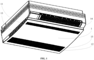
FIG. 1 is a schematic view showing an overall structure of the air conditioner of the present embodiment; -
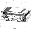
FIG. 2 is a schematic view showing a working state of the air conditioner of the present embodiment in a heating mode; -
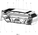
FIG. 3 is a schematic view showing the working state of the air conditioner of the present embodiment in a cooling mode; -
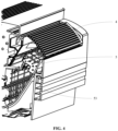
FIG. 4 is a schematic view showing a connection structure of an upper swing blade with a first connecting rod of the present embodiment; -
FIG. 5 is a schematic view showing a connection structure of a lower swing blade with a second connecting rod of the present embodiment; -
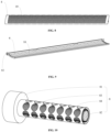
FIG. 6 is a schematic structural view of the upper swing blade of the present embodiment; -
FIG. 7 is a schematic structural view of the lower swing blade of the present embodiment; -
FIG. 8 is a schematic structural view of an upper air guide plate of the present embodiment; -
FIG. 9 is a schematic structural view of a lower air guide plate of the present embodiment; -
FIG. 10 is a schematic structural view of a sterilization device of the present embodiment; and -
FIG. 11 is a schematic flowchart of the control method for the air conditioner of the present embodiment. -
- 1: housing; 11: upper air inlet; 12: lower air inlet; 13: side air inlet; 14: upper air outlet; 15: lower air outlet;
- 2: indoor heat exchanger;
- 3: fan;
- 4: upper air guide plate;
- 5: upper swing blade; 51: second rotating shaft; 52: first hinge end; 53: first connecting rod;
- 6: lower air guide plate; 61: third rotating shaft;
- 7: lower swing blade; 71: fourth rotating shaft; 72: second hinge end; 73: second connecting rod;
- 8: sterilization device; 81: mounting seat; 82: ultraviolet lamp tube; 83: outer cover; 84: nano catalytic plate;
- 9: filter screen;
- 10: air hole.
- Preferred embodiments of the present disclosure will be described below with reference to the accompanying drawings. It should be understood by those skilled in the art that these embodiments are only used to explain the technical principles of the present disclosure, and are not intended to limit the scope of protection of the present disclosure. For example, although the first preset angle, the second preset angle, the third preset angle and the fourth preset angle of the upper air guide plate or the lower air guide plate are described with specific numerical values when illustrating the control method for the air conditioner of the present embodiment, these specific numerical values are not invariable, and those skilled in the art can adjust them as required to adapt to specific application scenes without departing from the principle of the present disclosure.
- It should be noted that in the description of the present disclosure, terms indicating directional or positional relationships, such as "center", "upper", "lower", "left", "right", "vertical", "horizontal", "inner", "outer" and the like, are based on the directional or positional relationships shown in the accompanying drawings. They are only used for ease of description, and do not indicate or imply that the device or element must have a specific orientation, or be constructed or operated in a specific orientation, and therefore they should not be considered as limitations to the present disclosure. In addition, terms "first", "second" and "third" are only used for descriptive purposes, and should not be interpreted as indicating or implying relative importance.
- In addition, it should also be noted that in the description of the present disclosure, unless otherwise clearly specified and defined, terms "mount", "connect" and "connection" should be understood in a broad sense; for example, the connection may be a fixed connection, or may also be a detachable connection, or an integral connection; it may be a mechanical connection, or an electrical connection; it may be a direct connection, or an indirect connection implemented through an intermediate medium, or it may be internal communication between two elements. For those skilled in the art, the specific meaning of the above terms in the present disclosure can be interpreted according to specific situations.
- In order to solve the above problem in the prior art, that is, to solve the problem in existing air conditioners that people can quickly feel a heating effect only when the wind blows directly on the human body in a case where the air conditioner is operating in the heating mode, but people's comfort will be reduced and even may get sick when the cold wind blows directly on the human body in a case where the air conditioner is operating in the cooling mode, the present disclosure provides a new air conditioner. As shown in
FIG. 1 to FIG. 3 , the air conditioner includes ahousing 1, as well as anindoor heat exchanger 2, afan 3, an upper air guide plate 4 (as shown inFIG. 8 ), an upper swing blade 5 (as shown inFIG. 6 ), a lower air guide plate 6 (as shown inFIG. 9 ) and a lower swing blade 7 (as shown inFIG. 7 ) that are provided in thehousing 1; thehousing 1 is provided with an air inflow portion, anupper air outlet 14 and alower air outlet 15, and theupper air outlet 14 and thelower air outlet 15 are both arranged on a front side of thehousing 1. - An upper air exhaust section is formed between the
fan 3 and theupper air outlet 14, and a lower air exhaust section is formed between thefan 3 and thelower air outlet 15; the upperair guide plate 4 is rotatably connected to the upper air exhaust section through a first rotating shaft (not shown in the figure), and the upperair guide plate 4 rotates around the first rotating shaft to adjust an opening size of the upper air exhaust section; theupper swing blade 5 is arranged in the upper air exhaust section and is located between thefan 3 and the upperair guide plate 4; a second rotatingshaft 51 of theupper swing blade 5 is rotatably connected to a skeleton in thehousing 1, and afirst hinge end 52 of theupper swing blade 5 is hinged with a first connecting rod 53 (as shown inFIG. 4 ); the first connectingrod 53 is perpendicular to the second rotatingshaft 51, and the first connectingrod 53 drives theupper swing blade 5 to swing around the second rotatingshaft 51 when the first connectingrod 53 performs a push-pull movement; as shown inFIG. 5 , the lowerair guide plate 6 is rotatably connected to the lower air exhaust section through a third rotatingshaft 61, and the lowerair guide plate 6 rotates around the third rotatingshaft 61 to adjust an opening size of the lower air exhaust section; thelower swing blade 7 is arranged in the lower air exhaust section and is located between the lowerair guide plate 6 and thelower air outlet 15; as shown inFIG. 5 , a fourthrotating shaft 71 of thelower swing blade 7 is rotatably connected to the skeleton in thehousing 1, and asecond hinge end 72 of thelower swing blade 7 is hinged with a second connecting rod 73; the second connecting rod 73 is perpendicular to the fourth rotatingshaft 71, and the second connecting rod 73 drives thelower swing blade 7 to swing around the fourth rotatingshaft 71 when the second connecting rod 73 performs a push-pull movement; the air conditioner also includes a first motor (not shown in the figure) for driving the upperair guide plate 4 to rotate, a second motor (not shown in the figure) for driving the first connectingrod 53 to perform a push-pull movement, a third motor (not shown in the figure) for driving the lowerair guide plate 6 to rotate, and a fourth motor (not shown in the figure) for driving the second connecting rod 73 to perform a push-pull movement. - Exemplarily, as shown in
FIG. 1 , the air inflow portion provided on thehousing 1 includes anupper air inlet 11 and alower air inlet 12 arranged on the front side of thehousing 1, and aside air inlet 13 arranged on a side face of thehousing 1. It can be seen fromFIG. 2 andFIG. 3 that thelower air inlet 12 and thelower air outlet 15 of the present embodiment adjoin to each other and share an air grille for supplying air to the room, but a partition is provided between the lower air exhaust section and an air inflow section inside thehousing 1 to isolate the two. In addition, it can be understood that an air inlet may also be provided on a rear side or a top of thehousing 1. The normal air introduction function of the air conditioner can be realized by merely arranging any one of the above air inlets on thehousing 1. - In the air conditioner as shown in
FIGS. 2 and3 , the wind in the upper air exhaust section first changes a wind direction thereof through the swinging of theupper swing blade 5, then a main wind direction is determined by the upperair guide plate 4; the upperair guide plate 4 can also adjust the air volume by adjusting an opening angle. Since the blowing wind passes through the upperair guide plate 4, the upperair guide plate 4 can be directly arranged at theupper air outlet 14. - The air volume of the wind in the lower air exhaust section is first adjusted by the lower
air guide plate 6, and then the wind direction thereof is changed through the swinging of thelower swing blade 7. Since the blowing wind of thelower air outlet 15 is adjusted through the swinging of thelower swing blade 7 afterward, compared with theupper air outlet 14, the wind blowing from thelower air outlet 15 is gentler. Theupper swing blade 5 and thelower swing blade 7 provided with the air holes 10 divide the blowing wind into two categories: one of which flows along their surfaces and the other of which flows along theirown air holes 10 to achieve the purpose of changing the wind direction. At the same time, on one hand, theupper swing blade 5 and thelower swing blade 7 can change the wind direction by simply adjusting the angle of the swing blade, and on the other hand, theupper swing blade 5 and thelower swing blade 7 can also constantly change the wind direction by periodically swinging. - As shown in
FIG. 6 to FIG. 9 , the upperair guide plate 4, theupper swing blade 5, the lowerair guide plate 6 and thelower swing blade 7 are each provided with a plurality ofair holes 10 extending along their own thickness direction, so that when the air flows in the upper air exhaust section and lower air exhaust section of the air conditioner and blows into the room through theupper air outlet 14 and thelower air outlet 15, different directions of airflows are formed, so that the blowing wind is gentler and is prevented from blowing directly on the human body. - As shown in
FIGS. 2 and3 , the first rotating shaft of the upperair guide plate 4 is perpendicular to the secondrotating shaft 51 of theupper swing blade 5, so that a rotation direction of the upperair guide plate 4 also intersects the swinging direction of theupper swing blade 5, thus enabling the wind blowing from theupper air outlet 14 to be gentler by changing the wind direction for many times; the thirdrotating shaft 61 of the lowerair guide plate 6 is perpendicular to the fourthrotating shaft 71 of thelower swing blade 7, so that a rotation direction of the lowerair guide plate 6 also intersects the swinging direction of thelower swing blade 7, thus enabling the wind blowing from thelower air outlet 15 to be gentler by changing the wind direction for many times. - In the air conditioner as shown in
FIGS. 2 and3 , theindoor heat exchanger 2 in the present embodiment is a fin type heat exchanger, and theindoor heat exchanger 2 is arranged on an air inflow side of thefan 3; the air conditioner in the present embodiment further includes afilter screen 9 arranged inside thehousing 1, and thefilter screen 9 is located between the air inflow portion and theindoor heat exchanger 2. Only a fixing frame for mounting thefilter screen 9 is shown inFIG. 2 andFIG. 3 , so that thefilter screen 9 can be described exemplarily. When the air conditioner is working, indoor wind enters the interior of the air conditioner from the air inflow portion, passes through thefilter screen 9, theindoor heat exchanger 2 and thefan 3 in sequence, and then enters the upper air exhaust section and the lower air exhaust section respectively. - The first motor, the second motor, the third motor and the fourth motor in the air conditioner of the present embodiment can be communicatively connected with a signal output terminal of a controller in the air conditioner, and a signal input terminal of the controller can be communicatively connected with a temperature sensor configured to monitor an actual indoor temperature. The controller automatically controls the upper
air guide plate 4, theupper swing blade 5, the lowerair guide plate 6 and thelower swing blade 7 according to a comparison result of the actual indoor temperature and a user preset temperature fed back by the temperature sensor and the working mode of the air conditioner, so that the user's experience in use in the heating mode and the cooling mode can be further improved. -
FIG. 2 is a schematic view showing a working state of the air conditioner of the present embodiment in the heating mode, in which the upperair guide plate 4 and the lowerair guide plate 6 are both in an open state; moreover, theupper swing blade 5 is consistent with the wind direction of theupper air outlet 14, and thelower swing blade 7 is consistent with the wind direction of thelower air outlet 15.FIG. 3 is a schematic view showing the working state of the air conditioner of the present embodiment in the cooling mode, in which the upperair guide plate 4 is opened by a certain angle, whereas the lowerair guide plate 6 is in a closed state, and both theupper swing blade 5 and thelower swing blade 7 swing periodically. - In an air conditioner provided by the present embodiment, the
upper air outlet 14 and thelower air outlet 15 are provided on the front side ofhousing 1, the upperair guide plate 4 and theupper swing blade 5 are provided between theupper air outlet 14 and thefan 3, and the lowerair guide plate 6 and thelower swing blade 7 are provided between thelower air outlet 15 and thefan 3. In this way, the air conditioner can open the angles of the upperair guide plate 4 and the lowerair guide plate 6 to the maximum in an initial stage of heating, and at the same time can control theupper swing blade 5 to be consistent with the wind direction of theupper air outlet 14, and thelower swing blade 7 to be consistent with the wind direction of thelower air outlet 15, so that people can quickly feel the heating effect; the air conditioner can also open the upperair guide plate 4 to a preset angle (such as 45°) in an early stage of cooling, close the lowerair guide plate 6, and at the same time can control theupper swing blade 5 and thelower swing blade 7 to swing periodically to prevent the cold wind from blowing directly on the human body. Therefore, the air conditioner can ensure the user's experience in use in both the heating mode and the cooling mode. - Generally, in the air conditioner, bacteria in the air are killed by an ultraviolet light sterilization device. However, since the wind in the conventional air conditioner generally blows directly, the time that the ultraviolet light sterilization device sterilizes the bacteria in the wind is short, thus failing to sufficiently kill the bacteria in the wind blowing into the room. In addition, ozone generated when the general ultraviolet light sterilization device utilizes C-wave ultraviolet light for sterilization will also have an adverse effect on human health.
- In order to solve the above problems, as shown in
FIGS. 2 and3 , the air conditioner of the present embodiment is also provided with asterilization device 8 in the upper air exhaust section and the lower air exhaust section respectively. Exemplarily, as shown inFIG. 10 , thesterilization device 8 includes a mountingseat 81, anultraviolet lamp tube 82 and anouter cover 83 that are connected to the mountingseat 81. Theouter cover 83 is sleeved over the outside of theultraviolet lamp tube 82, and a nanocatalytic plate 84 is provided on theouter cover 83. - The ultraviolet light emitted from the
ultraviolet lamp tube 82 of thesterilization device 8 itself of the present embodiment contacts with the nanocatalytic plate 84 to obtain hydroxyl radicals to kill the bacteria in the air; through the periodic swinging of theupper swing blade 5 or thelower swing blade 7, the air can fully mix with the hydroxyl radicals to enhance the sterilizing effect. The hydroxyl radicals will oxidize bacteria, viruses and other harmful substances in the air into water and carbon dioxide without generation of ozone. In addition to killing microorganisms (bacteria, viruses, etc.), the hydroxyl radicals can also decompose harmful gases, volatile organic compounds such as formaldehyde and benzene, smoke smell and fine 0.01µm airborne particles due to their super strong oxidizing ability. Thesterilization device 8 of the present embodiment can not only purify the air inside the air conditioner, but also release purification factors (hydroxyl radicals and superoxide radicals) to every corner of the room with the wind, actively capture and purify bacteria, viruses and harmful gases. - In addition, in the air conditioner of the present embodiment, a titanium oxide coating may also be provided on outer surfaces of the upper
air guide plate 4, theupper swing blade 5, the lowerair guide plate 6 and thelower swing blade 7; theouter cover 83 is provided with light-transmitting holes (not shown in the figure) for the ultraviolet light to exit and irradiate the titanium oxide coating. In this way, the ultraviolet light emitted from the light-transmitting holes can also contact with the titanium oxide coating provided on the outer surfaces of the upperair guide plate 4, theupper swing blade 5, the lowerair guide plate 6 and thelower swing blade 7 to generate hydroxyl radicals, so as to further enhance the sterilizing effect. - Of course, the above alternative implementations, as well as the alternative implementations and preferred implementations, can also be used in cooperation with each other, so as to obtain new implementations suitable for more specific application scenes through combination.
- Then, in the control method for the air conditioner provided by the present embodiment, as shown in
FIGS. 2 and3 , anindoor heat exchanger 2 and afan 3 are arranged in ahousing 1 of the air conditioner, anupper air outlet 14 and alower air outlet 15 are arranged on a front side of thehousing 1, an upperair guide plate 4 and anupper swing blade 5 are arranged between theupper air outlet 14 and thefan 3, and a lowerair guide plate 6 and alower swing blade 7 are arranged between thelower air outlet 15 and thefan 3; the upperair guide plate 4 and the lowerair guide plate 6 are respectively provided with a plurality ofair holes 10 extending in their own thickness direction; as shown inFIG. 11 , the control method for the air conditioner includes: - S 1: acquiring an actual indoor temperature;
- S2: comparing the actual indoor temperature with a user preset temperature;
- S3: determining whether an actual working mode of the air conditioner is a heating mode or a cooling mode; and
- S4: controlling the upper
air guide plate 4, theupper swing blade 5, the lowerair guide plate 6 and thelower swing blade 7 based on the actual working mode and a comparison result. - It should be noted that the necessary descriptions of the relevant structure of the air conditioner are given herein all for the purpose of clearly and completely explaining the control method for the air conditioner of the present embodiment. For a more detailed description of the structure of the air conditioner, reference may be made to the foregoing description of the present embodiment, and a repeated description will be omitted herein. However, it should also be understood by those skilled in the art that the foregoing description of the specific structure of the air conditioner cannot be used as an improper limitation to the scope of application of the control method for the air conditioner provided by the present embodiment. In addition to the above air conditioner, the present disclosure may also be applied to other similar air conditioners, which may be a bedside air conditioner or other air conditioners such as a cabinet air conditioner.
- In the control method for the air conditioner according to the present embodiment, based on whether the actual working mode of the air conditioner is the heating mode or the cooling mode and a result of comparing the actual indoor temperature with the user preset temperature, the upper
air guide plate 4, theupper swing blade 5, the lowerair guide plate 6 and thelower swing blade 7 of the air conditioner are controlled. Therefore, in the air conditioner of the present embodiment, a working state of the air conditioner can be automatically and timely adjusted according to the different heating mode and cooling mode of the actual working mode of the air conditioner, and the difference between the actual indoor temperature and the user preset temperature, so it is ensured that people can quickly feel the heating effect when the air conditioner is operating in the heating mode, and cold wind is also prevented from blowing directly on the human body when the air conditioner is operating in the cooling mode, so that the user's experience in use is always guaranteed. - It should be noted that although the specific steps of the method of the present disclosure have been described above in detail, those skilled in the art can combine, split the above steps and exchange the order thereof without departing from the basic principle of the present disclosure. The thus-modified technical solutions do not change the basic idea of the present disclosure, and therefore also fall within the scope of protection of the present disclosure. For example, in addition to being executed after steps S1 and S2, step S3 may also be executed simultaneously with steps S1 or S2, or executed before steps S1 and S2.
- As a preferred implementation of the above control method for the air conditioner provided by the present embodiment, the step of controlling the upper
air guide plate 4, theupper swing blade 5, the lowerair guide plate 6 and thelower swing blade 7 based on the actual working mode and the comparison result in step S4 includes: - (I) in a case where the actual working mode is a heating mode:
- 1) if the actual indoor temperature is lower than the user preset temperature and a temperature difference between the actual indoor temperature and the user preset temperature is larger than or equal to a preset first temperature difference threshold, then adjusting opening degrees of the upper
air guide plate 4 and the lowerair guide plate 6 to a first preset angle.
- 1) if the actual indoor temperature is lower than the user preset temperature and a temperature difference between the actual indoor temperature and the user preset temperature is larger than or equal to a preset first temperature difference threshold, then adjusting opening degrees of the upper
- Exemplarily, in this case, the actual indoor temperature is much lower than the user preset temperature, and it is urgently necessary to increase the indoor temperature to meet the user's requirement on the indoor temperature. Therefore, the upper
air guide plate 4 or the lowerair guide plate 6 may be adjusted to the maximum opening angle. The first preset angle may be set as the maximum opening angle, or other angles set for quick heating. The first temperature difference threshold may be set to 5°C, or in a specific implementation, the first temperature difference threshold may be set to any value from 3°C to 7°C. - Further, at this time, the
upper swing blade 5 can be controlled to be consistent with a wind direction of theupper air outlet 14, and thelower swing blade 7 can be controlled to be consistent with a wind direction of thelower air outlet 15. In this way, theupper swing blade 5 and thelower swing blade 7 can cooperate with the upperair guide plate 4 and the lowerair guide plate 6 to jointly ensure the maximum air volume during heating. - 2) if the actual indoor temperature is higher than or equal to the user preset temperature, then adjusting the opening degrees of the upper
air guide plate 4 and the lowerair guide plate 6 to a second preset angle; in which the first preset angle is larger than the second preset angle. - Exemplarily, in this case, the main function of the air conditioner is to keep the indoor temperature, and at the same time to ensure the user's experience in use. At this time, it is necessary to reduce the opening degrees of the upper
air guide plate 4 and the lowerair guide plate 6 from the first preset angle to the second preset angle, and the second preset angle is an angle at which the wind will not blow directly on the human body and at the same time the indoor temperature can also be effectively kept. For example, the second preset angle may be 45°. - Further, at this time, the
upper swing blade 5 and thelower swing blade 7 can be controlled to swing periodically, so as to cooperate with the upperair guide plate 4 and the lowerair guide plate 6, and make the hot wind blowing from theupper air outlet 14 and thelower air outlet 15 gentler, thus ensuring the user's experience in use.
(II) in a case where the actual working mode is a cooling mode: - 1) if the actual indoor temperature is higher than the user preset temperature and a temperature difference between the actual indoor temperature and the user preset temperature is larger than or equal to a preset second temperature difference threshold, then adjusting the opening degree of the upper
air guide plate 4 to a third preset angle, and at the same time, adjusting the opening degree of the lowerair guide plate 6 to a fourth preset angle; in which the third preset angle is larger than the fourth preset angle. - Exemplarily, in this case, the actual indoor temperature is much higher than the user preset temperature, and it is necessary to quickly reduce the indoor temperature to the user preset temperature. Since a lower exhaust port of the air conditioner is within the height range of the bed (or the user), and the height of an upper exhaust port of the air conditioner is much higher than the height of the bed (or the user), in order to reduce the indoor temperature to the user preset temperature as soon as possible and reduce or prevent the cold wind from blowing directly on the human body, the fourth preset angle should be set smaller than the third preset angle. For example, the fourth preset angle is set to close the lower
air guide plate 6, and the third preset angle may be set to 45°, so as to greatly reduce or prevent the cold wind from blowing directly on the human body. In addition, the second temperature difference threshold may be set to 5°C; or in a further implementation, the second temperature difference threshold may be set to any value from 3°C to 7°C, and the magnitudes of the first temperature difference threshold and the second temperature difference threshold may be the same or may also be different. - Further, at this time, the
upper swing blade 5 and thelower swing blade 7 can be controlled to swing periodically, so as to cooperate with the upperair guide plate 4 and the lowerair guide plate 6, so that the cold wind blowing from theupper air outlet 14 and thelower air outlet 15 can be made gentler more effectively, thus improving the user's experience in use. - 2) if the actual indoor temperature is lower than or equal to the user preset temperature, then adjusting the opening degrees of both the upper
air guide plate 4 and the lowerair guide plate 6 to a fourth preset angle. The fourth preset angle may be set to close the upperair guide plate 4 or the lowerair guide plate 6. - Exemplarily, in this case, the main function of the air conditioner is to keep the indoor temperature, and at the same time to ensure the user's experience in use. Since the upper
air guide plate 4 and the lowerair guide plate 6 in the present embodiment are respectively provided with a plurality ofair holes 10 extending along their own thickness direction, when the upperair guide plate 4 and the lowerair guide plate 6 are closed, the volume of wind blowing from theupper air outlet 14 and thelower air outlet 15 can be reduced, and the blowing cold wind can be gentler. The fourth preset angle is an angle at which the upperair guide plate 4 or the lowerair guide plate 6 is closed. - Further, at this time, the
upper swing blade 5 can be controlled to be consistent with the wind direction of theupper air outlet 14, and thelower swing blade 7 can be controlled to be consistent with the wind direction of thelower air outlet 15, so as to cooperate with the upperair guide plate 4 and the lowerair guide plate 6 to ensure an effective cooling effect and at the same time give considerations to the user's experience in use. - As a preferred implementation of the above control method for the air conditioner provided by the present embodiment, a refrigerant circulation loop is formed between the
indoor heat exchanger 2 and a compressor arranged outdoors (not shown in the figure), and when controlling the upperair guide plate 4, theupper swing blade 5, the lowerair guide plate 6 and thelower swing blade 7 based on the actual working mode and the comparison result in step S4, the control method further includes: - 1) in a case where the actual working mode is a heating mode, if the actual indoor temperature is lower than the user preset temperature and a temperature difference between the actual indoor temperature and the user preset temperature is larger than or equal to a preset first temperature difference threshold, or in a case where the actual working mode is a cooling mode, if the actual indoor temperature is higher than the user preset temperature and a temperature difference between the actual indoor temperature and the user preset temperature is larger than or equal to a preset second temperature difference threshold, then controlling the compressor to run at a first preset power. In this way, a higher cooling or heating effect of the air conditioner is ensured at this time.
- 2) if the actual working mode is a heating mode and the actual indoor temperature is higher than or equal to the user preset temperature, or if the actual working mode is a cooling mode and the actual indoor temperature is lower than or equal to the user preset temperature, then controlling the compressor to run at a second preset power. In this case, the compressor is reduced from the first preset power to the second preset power, so that at the same time of keeping the indoor temperature, the user's experience in use can also be ensured and electric energy can be saved. The first preset power is larger than the second preset power.
- Exemplarily, in the control method for the air conditioner of the present embodiment, according to the different heating mode and cooling mode of the actual working mode of the air conditioner and the difference between the actual indoor temperature and the user preset temperature, the air conditioner of the present embodiment controls the upper
air guide plate 4, theupper swing blade 5, the lowerair guide plate 6, thelower swing blade 7 and the compressor of the air conditioner, and adjusts a working state of the air conditioner automatically and timely. Therefore, it is ensured that people can quickly feel the heating effect when the air conditioner is operating in the heating mode, and cold wind is also prevented from blowing directly on the human body when the air conditioner is operating in the cooling mode, so that the user's experience in use is always guaranteed, and at the same time the air conditioner can be more power-saving. - As a preferred implementation of the above control method for the air conditioner provided by the present embodiment, before controlling the upper
air guide plate 4, theupper swing blade 5, the lowerair guide plate 6 and thelower swing blade 7 based on the actual working mode and the comparison result in step S4, the control method further includes: calculating a temperature difference between the actual indoor temperature and the user preset temperature; acquiring a heating time for the temperature difference equal to a first temperature difference threshold to change until the actual indoor temperature is equal to the user preset temperature during first-time heating of the air conditioner; determining a change relationship of the opening degrees of the upperair guide plate 4 and/or the lowerair guide plate 6 with time according to a first preset angle and a second preset angle of the upperair guide plate 4 and/or the lowerair guide plate 6 and the heating time; and adjusting the opening degrees of the upperair guide plate 4 and/or the lowerair guide plate 6 during later heating according to the change relationship. - Exemplarily, when the size of the indoor space is fixed, the time for the same air conditioner to adjust the indoor temperature from a certain temperature to another temperature is basically unchanged. As the actual indoor temperature approaches the user preset temperature, the opening degrees of the upper
air guide plate 4 and the lowerair guide plate 6 are gradually reduced from the first preset angle to the second preset angle. The change relationship of the opening degrees of the upperair guide plate 4 and/or the lowerair guide plate 6 with time may be a linear relationship or a stepwise changing relationship. - When adjusting the opening degrees of the upper
air guide plate 4 and/or the lowerair guide plate 6 during later heating according to the change relationship, in the heating process, the air conditioner realizes a gradual transition from focusing on the heating effect in the early stage of heating to focusing on the user experience in the later stage of heating, and realizes an optimal configuration between the heating effect and the user experience. Of course, it can be understood by those skilled in the art that the same method can also be used to adjust the opening degrees of the upperair guide plate 4 and/or the lowerair guide plate 6 of the air conditioner in the cooling mode. - As another preferred implementation of the above control method for the air conditioner provided by the present embodiment, before controlling the upper
air guide plate 4, theupper swing blade 5, the lowerair guide plate 5 and thelower swing blade 7 based on the actual working mode and the comparison result in step S4, the control method further includes: calculating a temperature difference between the actual indoor temperature and the user preset temperature; and controlling the opening degree of the upperair guide plate 4 or the lowerair guide plate 6 according to a preset correspondence relationship between the opening degrees of the upperair guide plate 4 and/or the lowerair guide plate 6 and the temperature difference. Using this method, a gradual transition from focusing on the heating effect in the early stage of heating to focusing on the user experience in the later stage of heating of the air conditioner in the heating process can also be realized, so as to realize an optimal configuration between the heating effect and the user experience. - It should be understood by those skilled in the art that the control method for the air conditioner provided by the present embodiment may be stored as a program in a computer-readable storage medium. The storage medium includes several instructions for causing a computer device (which may be a personal computer, a server, or a network device, etc.) or a processor to execute some steps of the methods of various embodiments of the present disclosure. The above storage medium includes: a U disk, a mobile hard disk, a read-only memory (ROM), a random access memory (RAM), a magnetic disk or an optical disk and other media that can store program codes.
- Furthermore, it will be understood by those skilled in the art that although some of the embodiments described herein include certain features included in other embodiments rather than others features, combinations of features of different embodiments are meant to be within the scope of protection of the present disclosure and to form different embodiments. For example, in the claims of the present disclosure, any of the claimed embodiments may be used in any combination.
- Hitherto, the technical solutions of the present disclosure have been the in connection with the preferred embodiments shown in the accompanying drawings, but it is easily understood by those skilled in the art that the scope of protection of the present disclosure is obviously not limited to these specific embodiments. Without departing from the principles of the present disclosure, those skilled in the art can make equivalent changes or replacements to relevant technical features, and all the technical solutions after these changes or replacements will fall within the scope of protection of the present disclosure.
Claims (10)
- A control method for an air conditioner, wherein an indoor heat exchanger and a fan are arranged in a housing of the air conditioner; an upper air outlet and a lower air outlet are arranged on a front side of the housing, an upper air guide plate and an upper swing blade are arranged between the upper air outlet and the fan, and a lower air guide plate and a lower swing blade are arranged between the lower air outlet and the fan; the upper air guide plate and the lower air guide plate are respectively provided with a plurality of air holes extending in their own thickness direction, and the control method comprises:acquiring an actual indoor temperature;comparing the actual indoor temperature with a user preset temperature;determining whether an actual working mode of the air conditioner is a heating mode or a cooling mode; andcontrolling the upper air guide plate, the upper swing blade, the lower air guide plate and the lower swing blade based on the actual working mode and a comparison result.
- The control method according to claim 1, wherein the step of controlling the upper air guide plate, the upper swing blade, the lower air guide plate and the lower swing blade based on the actual working mode and the comparison result comprises:in a case where the actual working mode is a heating mode, if the actual indoor temperature is lower than the user preset temperature and a temperature difference between the actual indoor temperature and the user preset temperature is larger than or equal to a preset first temperature difference threshold, then adjusting opening degrees of the upper air guide plate and the lower air guide plate to a first preset angle; and if the actual indoor temperature is higher than or equal to the user preset temperature, then adjusting the opening degrees of the upper air guide plate and the lower air guide plate to a second preset angle; and/orin a case where the actual working mode is a cooling mode, if the actual indoor temperature is higher than the user preset temperature and a temperature difference between the actual indoor temperature and the user preset temperature is larger than or equal to a preset second temperature difference threshold, then adjusting the opening degree of the upper air guide plate to a third preset angle, and at the same time, adjusting the opening degree of the lower air guide plate to a fourth preset angle; and if the actual indoor temperature is lower than or equal to the user preset temperature, then adjusting the opening degrees of both the upper air guide plate and the lower air guide plate to a fourth preset angle;wherein the first preset angle is larger than the second preset angle, and the third preset angle is larger than the fourth preset angle.
- The control method according to claim 1, wherein the step of controlling the upper air guide plate, the upper swing blade, the lower air guide plate and the lower swing blade based on the actual working mode and the comparison result comprises:in a case where the actual working mode is a heating mode, if the actual indoor temperature is lower than the user preset temperature and a temperature difference between the actual indoor temperature and the user preset temperature is larger than or equal to a preset first temperature difference threshold, then controlling the upper swing blade to be consistent with a wind blowing direction of the upper air outlet, and controlling the lower swing blade to be consistent with a wind blowing direction of the lower air outlet; and/orin a case where the actual working mode is a heating mode, if the actual indoor temperature is higher than or equal to the user preset temperature, then controlling the upper swing blade and the lower swing blade to swing periodically.
- The control method according to claim 1, wherein the step of controlling the upper air guide plate, the upper swing blade, the lower air guide plate and the lower swing blade based on the actual working mode and the comparison result comprises:in a case where the actual working mode is a cooling mode, if the actual indoor temperature is higher than the user preset temperature and a temperature difference between the actual indoor temperature and the user preset temperature is larger than or equal to a preset second temperature difference threshold, then controlling the upper swing blade and the lower swing blade to swing periodically; and/orin a case where the actual working mode is a cooling mode, if the actual indoor temperature is lower than or equal to the user preset temperature, then controlling the upper swing blade to be consistent with a wind blowing direction of the upper air outlet, and controlling the lower swing blade to be consistent with a wind blowing direction of the lower air outlet.
- The control method according to claim 1, wherein a refrigerant circulation loop is formed between the indoor heat exchanger and a compressor arranged outdoors, and when controlling the upper air guide plate, the upper swing blade, the lower air guide plate and the lower swing blade based on the actual working mode and the comparison result, the control method further comprises:in a case where the actual working mode is a heating mode, if the actual indoor temperature is lower than the user preset temperature and a temperature difference between the actual indoor temperature and the user preset temperature is larger than or equal to a preset first temperature difference threshold, or in a case where the actual working mode is a cooling mode, if the actual indoor temperature is higher than the user preset temperature and a temperature difference between the actual indoor temperature and the user preset temperature is larger than or equal to a preset second temperature difference threshold, then controlling the compressor to run at a first preset power; and/orif the actual working mode is a heating mode and the actual indoor temperature is higher than or equal to the user preset temperature, or if the actual working mode is a cooling mode and the actual indoor temperature is lower than or equal to the user preset temperature, then controlling the compressor to run at a second preset power;wherein the first preset power is larger than the second preset power.
- The control method according to claim 1, wherein before controlling the upper air guide plate, the upper swing blade, the lower air guide plate and the lower swing blade based on the actual working mode and the comparison result, the control method further comprises:calculating a temperature difference between the actual indoor temperature and the user preset temperature;acquiring a heating time for the temperature difference equal to a first temperature difference threshold to change until the actual indoor temperature is equal to the user preset temperature during first-time heating of the air conditioner;determining a change relationship of opening degrees of the upper air guide plate and/or the lower air guide plate with time according to a first preset angle and a second preset angle of the upper air guide plate and/or the lower air guide plate and the heating time; andadjusting the opening degrees of the upper air guide plate and/or the lower air guide plate during later heating according to the change relationship.
- The control method according to claim 6, wherein the change relationship of the opening degrees of the upper air guide plate and/or the lower air guide plate with time is a linear relationship or is stepwise changing relationship.
- The control method according to claim 1, wherein before controlling the upper air guide plate, the upper swing blade, the lower air guide plate and the lower swing blade based on the actual working mode and the comparison result, the control method further comprises:calculating a temperature difference between the actual indoor temperature and the user preset temperature; andcontrolling opening degree of the upper air guide plate or the lower air guide plate according to a preset correspondence relationship between the opening degrees of the upper air guide plate and/or the lower air guide plate and the temperature difference.
- The control method according to claim 2, wherein the first preset angle is a maximum opening angle of the upper air guide plate or the lower air guide plate; and/orthe second preset angle and/or the third preset angle are 45°; and/orthe fourth preset angle is an angle at which the upper air guide plate or the lower air guide plate is closed.
- The control method according to claim 2, wherein the first temperature difference threshold and/or the second temperature difference threshold are 5°C; or
the first temperature difference threshold and/or the second temperature difference threshold are any value from 3°C to 7°C.
Applications Claiming Priority (2)
| Application Number | Priority Date | Filing Date | Title |
|---|---|---|---|
| CN202010344397.1A CN113639425B (en) | 2020-04-27 | 2020-04-27 | Control method of air conditioner |
| PCT/CN2021/078564 WO2021218349A1 (en) | 2020-04-27 | 2021-03-02 | Control method for air conditioner |
Publications (3)
| Publication Number | Publication Date |
|---|---|
| EP4145050A1 true EP4145050A1 (en) | 2023-03-08 |
| EP4145050A4 EP4145050A4 (en) | 2023-11-08 |
| EP4145050B1 EP4145050B1 (en) | 2025-10-08 |
Family
ID=78331744
Family Applications (1)
| Application Number | Title | Priority Date | Filing Date |
|---|---|---|---|
| EP21795743.0A Active EP4145050B1 (en) | 2020-04-27 | 2021-03-02 | Control method for air conditioner |
Country Status (3)
| Country | Link |
|---|---|
| EP (1) | EP4145050B1 (en) |
| CN (1) | CN113639425B (en) |
| WO (1) | WO2021218349A1 (en) |
Families Citing this family (8)
| Publication number | Priority date | Publication date | Assignee | Title |
|---|---|---|---|---|
| CN114543325B (en) * | 2022-01-24 | 2024-04-26 | 青岛海尔空调器有限总公司 | Method and device for controlling air conditioner swing blades, air conditioner, and storage medium |
| CN114413452B (en) * | 2022-02-17 | 2023-07-14 | 珠海格力电器股份有限公司 | Air volume control method of air conditioner and air conditioner |
| CN116857765A (en) * | 2022-03-28 | 2023-10-10 | 青岛海尔空调器有限总公司 | Air conditioner control device, method and device for representing running state of air conditioner |
| CN115076874B (en) * | 2022-05-26 | 2025-08-19 | 青岛海尔空调器有限总公司 | Noise reduction control method and system for air conditioner |
| CN115264814A (en) * | 2022-06-21 | 2022-11-01 | 青岛海尔空调器有限总公司 | Air supply control method of air conditioner and air conditioner |
| CN115494898B (en) * | 2022-09-26 | 2023-10-31 | 广州奥松电子股份有限公司 | Air conditioner intelligent control method based on temperature and humidity sensor |
| CN115468221B (en) * | 2022-09-29 | 2025-01-24 | 青岛海信日立空调系统有限公司 | Air conditioner indoor unit |
| CN120799606B (en) * | 2025-01-13 | 2026-04-24 | 美的集团武汉暖通设备有限公司 | Air conditioner and control method thereof |
Family Cites Families (13)
| Publication number | Priority date | Publication date | Assignee | Title |
|---|---|---|---|---|
| JPH1054576A (en) * | 1996-08-09 | 1998-02-24 | Toshiba Corp | Floor radiation system |
| JPH11201490A (en) * | 1998-01-20 | 1999-07-30 | Fujitsu General Ltd | Air conditioner |
| JPH11337153A (en) * | 1998-05-27 | 1999-12-10 | Hitachi Ltd | Air conditioner |
| JP2007285628A (en) * | 2006-04-18 | 2007-11-01 | Daikin Ind Ltd | Air conditioner |
| JP2010078254A (en) * | 2008-09-26 | 2010-04-08 | Mitsubishi Heavy Ind Ltd | Air conditioner |
| CN204629917U (en) * | 2015-01-05 | 2015-09-09 | 美的集团武汉制冷设备有限公司 | There is the air-conditioner of axial flow blower |
| CN104913443B (en) * | 2015-05-29 | 2017-10-13 | 广东美的制冷设备有限公司 | Air conditioner and its wind speed control method |
| CN107388369B (en) * | 2017-07-31 | 2020-05-22 | 广东美的制冷设备有限公司 | Cabinet air conditioner and control method thereof |
| CN107883540B (en) * | 2017-10-19 | 2021-03-19 | 广东美的制冷设备有限公司 | Air conditioner and its control method, control device, and computer-readable storage medium |
| CN109140712B (en) * | 2018-10-26 | 2021-04-27 | 广东美的制冷设备有限公司 | Air outlet control method, control device, air conditioner and storage medium of air conditioner |
| CN109780695A (en) * | 2018-12-20 | 2019-05-21 | 珠海格力电器股份有限公司 | Control method of double-through-flow air conditioner |
| CN110469909B (en) * | 2019-08-08 | 2022-01-25 | 广东美的制冷设备有限公司 | Air conditioner, control method and device thereof and readable storage medium |
| CN212538051U (en) * | 2020-04-27 | 2021-02-12 | 青岛海尔空调电子有限公司 | Air conditioner |
-
2020
- 2020-04-27 CN CN202010344397.1A patent/CN113639425B/en active Active
-
2021
- 2021-03-02 EP EP21795743.0A patent/EP4145050B1/en active Active
- 2021-03-02 WO PCT/CN2021/078564 patent/WO2021218349A1/en not_active Ceased
Also Published As
| Publication number | Publication date |
|---|---|
| EP4145050A4 (en) | 2023-11-08 |
| CN113639425B (en) | 2022-10-28 |
| WO2021218349A1 (en) | 2021-11-04 |
| CN113639425A (en) | 2021-11-12 |
| EP4145050B1 (en) | 2025-10-08 |
Similar Documents
| Publication | Publication Date | Title |
|---|---|---|
| EP4145050B1 (en) | Control method for air conditioner | |
| US11519614B2 (en) | Air conditioner with air purifying function | |
| CN212538051U (en) | Air conditioner | |
| EP3410023A1 (en) | Air conditioner indoor unit | |
| KR200439228Y1 (en) | Air Conditioner with Light Plasma Sterilizer | |
| JP2009511854A (en) | Auxiliary device to add to the air conditioner | |
| KR20040105281A (en) | air-conditioner system with ventilation | |
| CN112254253A (en) | Fresh air device and control method thereof | |
| WO2023279723A1 (en) | Fresh air control method and device for air conditioner | |
| WO2022257475A1 (en) | Sterilization control method for smart home system, and smart home system | |
| CN113432201A (en) | Air conditioner and air return circulating ion sterilization method of air conditioner | |
| CN116026009A (en) | Air conditioner control method, control device and air conditioner | |
| CN213514106U (en) | Air conditioner | |
| KR102904628B1 (en) | Floor type air conditioning system | |
| CN209744633U (en) | Sterilizing device for air conditioner and air conditioner with same | |
| CN217482874U (en) | Fan coil device and air conditioning equipment | |
| JP2022024279A (en) | Air conditioning control apparatus, air conditioning system, and air conditioning method | |
| KR102611904B1 (en) | Stand-type variable flow path heat exchange ventilation device and system | |
| CN212777702U (en) | a multifunctional fan | |
| KR20200134517A (en) | Heat exchanger | |
| KR102533493B1 (en) | An air conditioner | |
| CN213146754U (en) | Indoor air conditioner | |
| WO2022018983A1 (en) | Heat exchange ventilation device with air purification function | |
| CN116085971B (en) | Control method of air conditioner | |
| CN214891643U (en) | Partition ventilation integrated anti-virus system based on Internet of things |
Legal Events
| Date | Code | Title | Description |
|---|---|---|---|
| STAA | Information on the status of an ep patent application or granted ep patent |
Free format text: STATUS: THE INTERNATIONAL PUBLICATION HAS BEEN MADE |
|
| PUAI | Public reference made under article 153(3) epc to a published international application that has entered the european phase |
Free format text: ORIGINAL CODE: 0009012 |
|
| STAA | Information on the status of an ep patent application or granted ep patent |
Free format text: STATUS: REQUEST FOR EXAMINATION WAS MADE |
|
| 17P | Request for examination filed |
Effective date: 20220331 |
|
| AK | Designated contracting states |
Kind code of ref document: A1 Designated state(s): AL AT BE BG CH CY CZ DE DK EE ES FI FR GB GR HR HU IE IS IT LI LT LU LV MC MK MT NL NO PL PT RO RS SE SI SK SM TR |
|
| DAV | Request for validation of the european patent (deleted) | ||
| DAX | Request for extension of the european patent (deleted) | ||
| A4 | Supplementary search report drawn up and despatched |
Effective date: 20231010 |
|
| RIC1 | Information provided on ipc code assigned before grant |
Ipc: F24F 11/86 20180101ALI20231004BHEP Ipc: F24F 140/00 20180101ALI20231004BHEP Ipc: F24F 110/10 20180101ALI20231004BHEP Ipc: F24F 11/74 20180101ALI20231004BHEP Ipc: F24F 11/79 20180101ALI20231004BHEP Ipc: F24F 13/14 20060101ALI20231004BHEP Ipc: F24F 1/0014 20190101AFI20231004BHEP |
|
| GRAP | Despatch of communication of intention to grant a patent |
Free format text: ORIGINAL CODE: EPIDOSNIGR1 |
|
| STAA | Information on the status of an ep patent application or granted ep patent |
Free format text: STATUS: GRANT OF PATENT IS INTENDED |
|
| INTG | Intention to grant announced |
Effective date: 20250515 |
|
| GRAS | Grant fee paid |
Free format text: ORIGINAL CODE: EPIDOSNIGR3 |
|
| GRAA | (expected) grant |
Free format text: ORIGINAL CODE: 0009210 |
|
| STAA | Information on the status of an ep patent application or granted ep patent |
Free format text: STATUS: THE PATENT HAS BEEN GRANTED |
|
| AK | Designated contracting states |
Kind code of ref document: B1 Designated state(s): AL AT BE BG CH CY CZ DE DK EE ES FI FR GB GR HR HU IE IS IT LI LT LU LV MC MK MT NL NO PL PT RO RS SE SI SK SM TR |
|
| REG | Reference to a national code |
Ref country code: GB Ref legal event code: FG4D Ref country code: CH Ref legal event code: F10 Free format text: ST27 STATUS EVENT CODE: U-0-0-F10-F00 (AS PROVIDED BY THE NATIONAL OFFICE) Effective date: 20251008 |
|
| REG | Reference to a national code |
Ref country code: DE Ref legal event code: R096 Ref document number: 602021040130 Country of ref document: DE |
|
| REG | Reference to a national code |
Ref country code: IE Ref legal event code: FG4D |
|
| REG | Reference to a national code |
Ref country code: NL Ref legal event code: MP Effective date: 20251008 |
|
| REG | Reference to a national code |
Ref country code: AT Ref legal event code: MK05 Ref document number: 1845094 Country of ref document: AT Kind code of ref document: T Effective date: 20251008 |
|
| PG25 | Lapsed in a contracting state [announced via postgrant information from national office to epo] |
Ref country code: NL Free format text: LAPSE BECAUSE OF FAILURE TO SUBMIT A TRANSLATION OF THE DESCRIPTION OR TO PAY THE FEE WITHIN THE PRESCRIBED TIME-LIMIT Effective date: 20251008 |
|
| PG25 | Lapsed in a contracting state [announced via postgrant information from national office to epo] |
Ref country code: ES Free format text: LAPSE BECAUSE OF FAILURE TO SUBMIT A TRANSLATION OF THE DESCRIPTION OR TO PAY THE FEE WITHIN THE PRESCRIBED TIME-LIMIT Effective date: 20251008 |
|
| REG | Reference to a national code |
Ref country code: LT Ref legal event code: MG9D |
|
| PG25 | Lapsed in a contracting state [announced via postgrant information from national office to epo] |
Ref country code: NO Free format text: LAPSE BECAUSE OF FAILURE TO SUBMIT A TRANSLATION OF THE DESCRIPTION OR TO PAY THE FEE WITHIN THE PRESCRIBED TIME-LIMIT Effective date: 20260108 |
|
| PG25 | Lapsed in a contracting state [announced via postgrant information from national office to epo] |
Ref country code: FI Free format text: LAPSE BECAUSE OF FAILURE TO SUBMIT A TRANSLATION OF THE DESCRIPTION OR TO PAY THE FEE WITHIN THE PRESCRIBED TIME-LIMIT Effective date: 20251008 Ref country code: HR Free format text: LAPSE BECAUSE OF FAILURE TO SUBMIT A TRANSLATION OF THE DESCRIPTION OR TO PAY THE FEE WITHIN THE PRESCRIBED TIME-LIMIT Effective date: 20251008 Ref country code: AT Free format text: LAPSE BECAUSE OF FAILURE TO SUBMIT A TRANSLATION OF THE DESCRIPTION OR TO PAY THE FEE WITHIN THE PRESCRIBED TIME-LIMIT Effective date: 20251008 |
|
| PGFP | Annual fee paid to national office [announced via postgrant information from national office to epo] |
Ref country code: IT Payment date: 20260324 Year of fee payment: 6 |
|
| PG25 | Lapsed in a contracting state [announced via postgrant information from national office to epo] |
Ref country code: RS Free format text: LAPSE BECAUSE OF FAILURE TO SUBMIT A TRANSLATION OF THE DESCRIPTION OR TO PAY THE FEE WITHIN THE PRESCRIBED TIME-LIMIT Effective date: 20260108 |
|
| PG25 | Lapsed in a contracting state [announced via postgrant information from national office to epo] |
Ref country code: IS Free format text: LAPSE BECAUSE OF FAILURE TO SUBMIT A TRANSLATION OF THE DESCRIPTION OR TO PAY THE FEE WITHIN THE PRESCRIBED TIME-LIMIT Effective date: 20260208 |
|
| PG25 | Lapsed in a contracting state [announced via postgrant information from national office to epo] |
Ref country code: PT Free format text: LAPSE BECAUSE OF FAILURE TO SUBMIT A TRANSLATION OF THE DESCRIPTION OR TO PAY THE FEE WITHIN THE PRESCRIBED TIME-LIMIT Effective date: 20260209 |
|
| PG25 | Lapsed in a contracting state [announced via postgrant information from national office to epo] |
Ref country code: PL Free format text: LAPSE BECAUSE OF FAILURE TO SUBMIT A TRANSLATION OF THE DESCRIPTION OR TO PAY THE FEE WITHIN THE PRESCRIBED TIME-LIMIT Effective date: 20251008 |
|
| PG25 | Lapsed in a contracting state [announced via postgrant information from national office to epo] |
Ref country code: LV Free format text: LAPSE BECAUSE OF FAILURE TO SUBMIT A TRANSLATION OF THE DESCRIPTION OR TO PAY THE FEE WITHIN THE PRESCRIBED TIME-LIMIT Effective date: 20251008 |
|
| PG25 | Lapsed in a contracting state [announced via postgrant information from national office to epo] |
Ref country code: BG Free format text: LAPSE BECAUSE OF FAILURE TO SUBMIT A TRANSLATION OF THE DESCRIPTION OR TO PAY THE FEE WITHIN THE PRESCRIBED TIME-LIMIT Effective date: 20251008 |
|
| PG25 | Lapsed in a contracting state [announced via postgrant information from national office to epo] |
Ref country code: LT Free format text: LAPSE BECAUSE OF FAILURE TO SUBMIT A TRANSLATION OF THE DESCRIPTION OR TO PAY THE FEE WITHIN THE PRESCRIBED TIME-LIMIT Effective date: 20251008 |
|
| PG25 | Lapsed in a contracting state [announced via postgrant information from national office to epo] |
Ref country code: SM Free format text: LAPSE BECAUSE OF FAILURE TO SUBMIT A TRANSLATION OF THE DESCRIPTION OR TO PAY THE FEE WITHIN THE PRESCRIBED TIME-LIMIT Effective date: 20251008 |
|
| PG25 | Lapsed in a contracting state [announced via postgrant information from national office to epo] |
Ref country code: DK Free format text: LAPSE BECAUSE OF FAILURE TO SUBMIT A TRANSLATION OF THE DESCRIPTION OR TO PAY THE FEE WITHIN THE PRESCRIBED TIME-LIMIT Effective date: 20251008 |
|
| PG25 | Lapsed in a contracting state [announced via postgrant information from national office to epo] |
Ref country code: EE Free format text: LAPSE BECAUSE OF FAILURE TO SUBMIT A TRANSLATION OF THE DESCRIPTION OR TO PAY THE FEE WITHIN THE PRESCRIBED TIME-LIMIT Effective date: 20251008 |
|
| PG25 | Lapsed in a contracting state [announced via postgrant information from national office to epo] |
Ref country code: CZ Free format text: LAPSE BECAUSE OF FAILURE TO SUBMIT A TRANSLATION OF THE DESCRIPTION OR TO PAY THE FEE WITHIN THE PRESCRIBED TIME-LIMIT Effective date: 20251008 |
|
| PG25 | Lapsed in a contracting state [announced via postgrant information from national office to epo] |
Ref country code: SK Free format text: LAPSE BECAUSE OF FAILURE TO SUBMIT A TRANSLATION OF THE DESCRIPTION OR TO PAY THE FEE WITHIN THE PRESCRIBED TIME-LIMIT Effective date: 20251008 |
|
| PG25 | Lapsed in a contracting state [announced via postgrant information from national office to epo] |
Ref country code: SE Free format text: LAPSE BECAUSE OF FAILURE TO SUBMIT A TRANSLATION OF THE DESCRIPTION OR TO PAY THE FEE WITHIN THE PRESCRIBED TIME-LIMIT Effective date: 20251008 |
|
| PLBE | No opposition filed within time limit |
Free format text: ORIGINAL CODE: 0009261 |
|
| STAA | Information on the status of an ep patent application or granted ep patent |
Free format text: STATUS: NO OPPOSITION FILED WITHIN TIME LIMIT |