EP4145026A1 - Seal - Google Patents
Seal Download PDFInfo
- Publication number
- EP4145026A1 EP4145026A1 EP22192097.8A EP22192097A EP4145026A1 EP 4145026 A1 EP4145026 A1 EP 4145026A1 EP 22192097 A EP22192097 A EP 22192097A EP 4145026 A1 EP4145026 A1 EP 4145026A1
- Authority
- EP
- European Patent Office
- Prior art keywords
- side wall
- tubular side
- seal
- entrance
- conduit
- Prior art date
- Legal status (The legal status is an assumption and is not a legal conclusion. Google has not performed a legal analysis and makes no representation as to the accuracy of the status listed.)
- Pending
Links
Images






Classifications
-
- F—MECHANICAL ENGINEERING; LIGHTING; HEATING; WEAPONS; BLASTING
- F16—ENGINEERING ELEMENTS AND UNITS; GENERAL MEASURES FOR PRODUCING AND MAINTAINING EFFECTIVE FUNCTIONING OF MACHINES OR INSTALLATIONS; THERMAL INSULATION IN GENERAL
- F16K—VALVES; TAPS; COCKS; ACTUATING-FLOATS; DEVICES FOR VENTING OR AERATING
- F16K1/00—Lift valves or globe valves, i.e. cut-off apparatus with closure members having at least a component of their opening and closing motion perpendicular to the closing faces
- F16K1/16—Lift valves or globe valves, i.e. cut-off apparatus with closure members having at least a component of their opening and closing motion perpendicular to the closing faces with pivoted closure-members
- F16K1/18—Lift valves or globe valves, i.e. cut-off apparatus with closure members having at least a component of their opening and closing motion perpendicular to the closing faces with pivoted closure-members with pivoted discs or flaps
- F16K1/22—Lift valves or globe valves, i.e. cut-off apparatus with closure members having at least a component of their opening and closing motion perpendicular to the closing faces with pivoted closure-members with pivoted discs or flaps with axis of rotation crossing the valve member, e.g. butterfly valves
- F16K1/226—Shaping or arrangements of the sealing
- F16K1/2263—Shaping or arrangements of the sealing the sealing being arranged on the valve seat
Definitions
- the present invention relates to a seal for a butterfly valve assembly for a vacuum cleaner, a butterfly valve assembly which comprises a such a seal, and a vacuum cleaner which comprises such a butterfly valve assembly with such a seal.
- EP2644072 describes a known example (prior art) of a vacuum cleaner.
- the vacuum cleaner comprises two valve assemblies formed as butterfly valves 1005A, 1005B (using the same reference number as those used in EP2644072 ) which each comprise two circular flat disks 1015A, 1015B rigidly mounted on a rotatable shaft 1010A, 1010B. Rotation of the shafts 1010A, 101B about their longitudinal axes results in rotation of the disks 1015A, 1015B.
- the disks 1015A, 1015B are mounted on the shafts 1010A, 1010B in such a manner that the plane of the disks 1015A, 1015B pass through the longitudinal axis of the shaft 1010A, 1010B on which it is mounted, the plane extending radially away from the longitudinal axis of the shaft 1010A, 1010B on which it is mounted in a perpendicular direction.
- the two disks 1015A, 1015B of each butterfly valve 1005A, 1005B are mounted on the shaft 1010A, 1010B next to each along the shaft 1010A, 1010B in such a manner that the plane the two disk 1015A, 1015B extends at different angles perpendicularly from the longitudinal axis of the shaft 1010A, 101B relative to each other.
- Each disk in each pair of disks 1015A, 1015B of each valve 1005A, 1005B are mounted adjacent an entrance of a conduit 935A, 935B, 940A, 940B of a pair of corresponding conduits 935A, 935B, 940A, 940B.
- each valve can be rotated to move the two disks 1015A, 1015B on the shaft 1010A, 1010B between two positions, a first position where it covers the entrance of the adjacent conduit 935A, 935B, 940A, 940B and a second position where the disk 1015A, 1015B is orientated at an angle relative to the entrance of the adjacent conduit 935A, 935B, 940A, 940B, opening the entrance of the conduit 935A, 935B, 940A, 940B to allow a fluid such as air to pass through the conduit 935A, 935B, 940A, 940B.
- the two disks 1015A, 1015B on each shaft 1010A, 1010B of each valve are angularly mounted of the shaft 1010A, 1010B relative to each other so that when one disk 1015A, 1015B is in its first position to cover the entrance of its adjacent conduit 935A, 935B, 940A, 940B, the other second disk 1015A, 1015B is in its second position where the second disk 1015A, 1015B is orientated at an angle relative to the entrance of its adjacent conduit 935A, 935B, 940A, 940B, and vice versa.
- each disk 1015A, 1015B When each disk 1015A, 1015B is in its first position where it covers the entrance of the adjacent conduit 935A, 935B, 940A, 940B (as best seen in Figure 10D of EP2644072 ), the outer periphery of the disk 1015A, 1015B abuts against the inner wall of the entrance of the adjacent conduit 935A, 935B, 940A, 940B.
- the problem with this design is that it provides a poor seal with air still able to pass around the disk 1015A, 1015B, allowing air to continue to pass through the conduit 935A, 935B, 940A, 940B even the entrance of the conduit 935A, 935B, 940A, 940B is covered.
- a vacuum cleaner comprising at least one butterfly valve assembly in accordance with any one of claims 13 to 16.
- FIG. 1A to 1C and Figures 2A to 2D A prior art design of a valve arrangement in a vacuum cleaner will now be described with reference to Figures 1A to 1C and Figures 2A to 2D .
- the description and Figures 1A to 1C and Figures 2A to 2D correspond to the description and Figures 9A to 9C and Figures 10A to 10D of EP2644072 .
- the prior art design of valve arrangement in the vacuum cleaner described below with reference to Figures 1A to 1C and Figures 2A to 2D should be understood with reference to the description of EP2644072 .
- a separator plate 900 engages a tank rim (not shown) of a vacuum cleaner, separating a tank cavity (the collection chamber - not shown) from a cavity (not shown) of a vacuum head (not shown) (also called a motor chamber).
- the separator plate 900 includes a platform 905 (e.g., a generally circulate plate) and one or more leg members 907B, 907C.
- the platform 905 includes an upper (head facing) surface 910 and a lower (tank facing) surface 912.
- the shaped and dimensions of the platform 905 may be any suitable for its described purpose.
- the platform 905 may be substantially planar and possess a generally circular shape.
- the upper surface 910 of the platform 905 may further include one or more connection posts 917 that engage (e.g., mate, receive, etc.) corresponding connection posts (not shown) extending from the vacuum head. Fasteners may extend through the connection posts 917 to secure a lid (not shown) to the separator plate 900.
- a pair of diametrically opposed lips 920B extends axially (upward) from the perimetral wall 915 to provide an engagement member for latch devices (not shown).
- the platform 905 may further include one or more reinforcing ribs 921 spanning the platform upper surface 910 to enhance the strength of the platform.
- the leg members 907, 907C extending distally from the platform lower surface 912, are configured to elevate the platform 905 and, in particular, to suspend a filter system above a supporting surface when the separator is placed directly upon the supporting surface. That is the length of the legs is selected to prevent the filters from contacting the ground when the separator plate 900 and/or head is removed from the tank and set on a surface.
- the leg members 907C, 907B are located proximate the outer edge of the separator plate, being disposed at predetermined angular positions thereon.
- the leg members 907C, 907B are configured to key the separator plate 900 to a tank (not shown) such that the separator plate is oriented in a specific rotational position when inserted into the tank.
- the platform 905 includes a first forward leg, a second forward leg 907B, a first rearward leg 907C, and a second rearward leg.
- Each leg 907B, 907C includes a proximal leg portion 922 and a distal leg portion 925.
- the proximal leg portion 922 of the forward legs 907B includes a notch 927B (e.g., a tapered (V-shaped) notch) configured to receive a guide element (not shown) protruding from an interior surface of the tank.
- the guide element is positioned at predetermined positions along the tank.
- the notch 927B aligns with each of the tank guide elements such that the first guide element is received within the notch of the first forward leg and the second guide element is received within the notch of the second forward leg 907B.
- the notch of first leg member must be aligned with the first guide element and the notch 927B of the second leg member 907B must be aligned with the second guide element.
- the forward (notched) leg members 907B not be aligned with their corresponding guide elements (i.e., should the rotational position of the separator plate 900 differ from the normal/predetermined position such that no leg or an unnotched leg is aligned with the guide elements), insertion of the separator plate 900 into the tank cavity of a vacuum cleaner will be prohibited.
- the separator plate 900 further includes a conduit system to enable the flow of air between the tank (the collection chamber) and the head (the motor chamber) of a vacuum cleaner.
- the platform 905 of the separator plate 900 includes a central, raised platform or deck 902 with a first conduit pair 935 and a second conduit pair 940.
- the first conduit pair 935 includes a first (forward) suction conduit or port 935A and a first (rearward) cleaning conduit or port 935B.
- the second conduit pair 940 includes a second (forward) suction conduit or port 940A and a second (rearward) cleaning conduit or port 940B.
- the conduits 935A, 935B of the first conduit pair 935 are positioned such that the conduits are disposed over a first filter of the filter system of a vacuum cleaner, while the conduits 940A, 940B of the second conduit pair 940 are positioned such that they are disposed over a second filter of the filter system of the vacuum cleaner (i.e., each filter is in fluid communication with a conduit pair).
- each conduit 935A, 935B, 940A, 940B may possess any shape and dimensions suitable for their described purpose.
- each conduit 935A, 935B, 940A, 940B may be generally cylindrical.
- Each conduit moreover, may include a conduit baffle operable to direct the airflow in a predetermined direction.
- the suction conduit 935A, 940A may include an inboard conduit baffle 942A that curves radially inward with respect to the platform 905 to direct the air inboard, while the cleaning conduits 935B, 940B may include an outboard conduit baffle 942B that curves radially outward to direct air outboard (toward the perimeter of the platform).
- the upper surface 910 of the platform 905 further includes first 945A, second 945B, and third 945C support walls that cooperate to support the airflow assembly.
- the first support wall 945A extends upward from the upper surface 910 of the platform 905, being oriented between the suction 935A, 940A and the cleaning 935B, 940B conduits.
- the second support wall 945B is disposed proximate the cleaning conduits 940A, 940B (i.e., is disposed outboard with respect to the first support wall).
- the third support wall 945C moreover, is positioned outboard from the second support wall 945B.
- Each support walls 945A - 945C is spaced from its adjacent support wall to define a cavity therebetween.
- first 945A and second 945B support walls define a fan cavity 950 that receives the fan of an airflow assembly.
- the second 945B and third 945C support walls cooperate to define a motor cavity 955 that receives the motor of the airflow assembly.
- Each support wall 945A, 945B, 945C includes a cut-out section 947 that receives and supports various components of the airflow assembly.
- the second and third support walls cooperate to support a motor of the airflow assembly, with the motor resting within the cut-out section.
- the motor cavity 955 further includes areas 957 for supporting valve solenoid switches (discussed in greater detail below).
- the separator plate 900 further includes a pair of opposed motor intake walls 958 extending from the third support wall 945C to the perimetral wall 915.
- the motor intake walls 958 cooperate with a motor shroud to define a motor air intake area 960 that aligns with second head vent.
- opposed walls 962 cooperate with the motor shroud to define a motor exhaust area 965 that aligns with a third head vent.
- a deflection wall or baffle 970 extends upward from platform upper surface 910 (e.g., the height of the wall may be substantially equal to or greater than the height of the deck 902).
- the platform baffle 970 is positioned between the deck 902 and the perimetral wall 915.
- the platform baffle 970 gradually curves such that it extends from a position along a lateral side of the deck 902 to a position along the forward side of the deck.
- the platform baffle 970 is operable to direct cooling air exhausted by a manifold toward electronics housed within the head, thereby cooling the electronics.
- the platform 905 further includes a first yoke 975A located proximate the first cleaning conduit 935B and a second yoke 975B located proximate the second cleaning conduit 940B.
- Each yoke 975A, 975B supports an associated butterfly valve 1005A, 1005B ( FIG. 2A ) of the valve assembly to enable rotation of the valve on the yoke (discussed in greater detail below).
- the platform lower surface 912 is best seen in FIG. 1C .
- platform lower surface 912 includes a recessed area 977 generally corresponding with the raised deck 902 of the platform upper surface 910.
- the perimetral wall 915 of the platform upper surface 910 moreover, defines a shoulder 980 on the platform lower surface 912.
- An axial wall 982 extends downward from the lower surface shoulder 980, being disposed slightly inboard from the circumference of the separator plate 900.
- the axial wall 982 is wrapped with a generally U-shaped sealing member or gasket 983 configured to contact the rim of the tank of a vacuum cleaner and thereby fluidly seal the joint between the tank rim and the shoulder 980.
- a series of downward-extending, angled fins 985 may be angularly spaced about the platform 905, being located near the outer edge of the platform, proximate the shoulder 980.
- the fins 985 serve as guides during the insertion of the separator plate 900 into the tank cavity.
- a bracket 990 is also disposed on the platform lower surface 912 that receives a conductive member 635 of the electrostatic discharge device. As shown, the conductive member 635 is coupled to the platform 905 via the conductive fastener 655.
- a valve assembly disposed on platform upper surface 910, opens and closes one or more of the separator conduits 935A, 935B, 940A, 940B to selectively permit fluid (air) therethrough.
- the valve assembly 1000 includes a first solenoid 1002A in communication with to a first butterfly valve 1005A and a second solenoid 1002B in communication with to a second butterfly valve 1005B.
- the first butterfly valve 1005A is supported by the first platform yoke 975A, while the second butterfly valve is supported by the second platform yoke 975B.
- valve assembly 1000 is positioned on the separator plate 900, with each solenoid 1002A, 1002B being positioned within areas 957 as described above.
- the solenoids 1002A, 1002B may be secured to the platform 905 by a cover or bridge 1040 coupled thereto.
- the first butterfly valve 1005A selectively permits airflow through the first conduit pair 935A, 935B.
- the second butterfly valve 1005B selectively permits airflow through the second conduit pair 940A, 940B.
- Each butterfly valve 1005A, 1005B includes an elongated shaft 1010A, 1010B supporting a first or distal disc 1015A and a second or proximal disc 1015B longitudinally spaced along the shaft and rotationally offset from the distal disc by, e.g., approximately 45°.
- the proximal end of the shaft 1010A, 1010B is connected to a crank arm 1017A, 1017B, which, in turn, is pivotally coupled to a linking member 1020A, 1020B via a pivot pin 1022A, 1022B.
- the linking member 1020A, 1020B is repositioned via a plunger 1025A, 1025B that is driven by the solenoid 1002A, 1002B. Specifically, the plunger 1025A, 1025B reciprocates axially to rotate the discs.
- the linking member 1020A, 1020B may further include a downward-extending, curved support or ski 1030A, 1030B configured to slide along the platform upper surface 910 as the plunger 1025A, 1025B reciprocates.
- each solenoid 1002A, 1002B may be selectively engaged to rotate the shaft 1010A, 1010B about its longitudinal axis in a clockwise or counter clockwise direction.
- the degree of rotation includes, but is not limited to, approximately 45°.
- the valve assembly 1000 may selectively position each disc 1015A, 1015B with respect to its associated conduit 935A, 935B, 940A, 940B to enable the passage of fluid (e.g., air) therethrough.
- the valve assembly 1000 rotationally positions the discs 1015A, 1015B in a first position, in which the suction conduits 935A, 940A are opened and the cleaning conduits 935B, 940B are closed. That is, the butterfly valve 1005A, 1005B positions the shaft 1010A, 1010B such that the first disc 1015A is oriented generally transverse to the opening defined by the suction conduit 935A, 940A (as illustrated in FIG.
- the second disc 1015B is positioned such that the disc completely covers the opening of the cleaning conduit 935B, 940B preventing the flow of air between the head 110 to the tank 105.
- the valves 1005A, 1005B may rotationally position the discs 1015A, 1015B in a second (reversed) position, in which the suction conduits 935A, 940A are closed and the cleaning conduits 935B, 940B are opened.
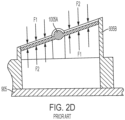
- the conduits 935A, 935B, 940A, 940B and discs 1015A, 1015B are configured such that air flowing through the conduit creates a balanced system in which the forces on the butterfly valve 1005A, 1005B are equally applied across both surfaces of the disc 1015A, 1015B (indicated by arrows F1 and F2).
- the downward force (F1 upper) on one side of the rotating axis is generally equal to the downward force (F2 upper) on the other side of the axis. Therefore, a pressure on the top side of the disk does not significantly increase the force necessary to toggle the valve.
- the conduit structure enables the use of a lower power solenoid since valve rotation does not require overcoming a significant eccentric force applied to the disc 1015A, 1015B by the air in or airflow through the conduit.
- the vacuum cleaner in accordance with the present invention is the same as the example of vacuum cleaner described above with reference to Figures 1 and 2 except for the design of the butterfly valves 1005A, 1005B.
- the butterfly valves 1005A, 1005B have been altered by changing the design of the conduits 935A, 935B, 940A, 940B and the addition of a seal in at least one of the conduits of each butterfly valve 1005A, 1005B.
- the same reference numbers have been used.
- each butterfly valve 1005A, 1005B comprises two conduits 935A, 935B, 940A, 940B.
- the edges 254 of the entrances 250 of the conduits 935B, 940B with the seals 200 are perpendicular relative to the longitudinal axis 252 of the conduit 935B, 940B resulting in the edge 254 of the entrance on all sides being the same height.
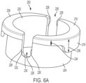
- FIG. 6A to 6E shows the seal 200.
- the seal 200 comprises a cap 206 and two concentric tubular side walls 202, 204 which surround a longitudinal axis 208 of the seal 200 and which are each connected at a first top end to the cap 206.
- the first inner tubular side wall 202 has a circular cross section in a direction perpendicular to the longitudinal axis 208, along the length of the first inner tubular side wall 202, the size of the cross section being constant and uniform along the length of the wall 202.
- the first inner tubular side wall 202 surrounds the longitudinal axis 208 in a symmetrical manner.
- the thickness 210 of wall 202 is constant around the longitudinal axis 208 of the seal 200 and along the length of the wall 202.
- the second outer tubular side wall 204 has a circular cross section in a direction perpendicular to the longitudinal axis 208, along the length of the second outer tubular side wall 204, the size of the cross section being constant and uniform along the length of the wall 204.
- the second outer tubular side wall 204 surrounds the longitudinal axis 208 in a symmetrical manner.
- the thickness 212 of wall 204 is constant around the longitudinal axis 208 of the seal 200 and along the length of the wall 204.
- the second outer tubular wall 204 surrounds the first inner tubular wall 202 in a concentric and symmetrical manner so that a constant radial gap 214 is formed between the two walls 202, 204 around the longitudinal axis 208 of the seal 200 and along the length of the walls 202, 204.
- the thickness 212 of the second outer tubular wall 204 is the same as that of the first inner tubular wall 202.
- the length of the second outer tubular wall 204 is slightly less than that of the first inner tubular wall 202.
- the cap 206 comprises an annular base 216 and an outer ring shaped rim 218 connected to outer periphery of the annular base 216 and which extends perpendicularly to the annular base 216.
- the two tubular walls 202, 204 attach to the underside of the annular base 216.
- the first inner wall 202 attaches to the annular base 216 adjacent the inner edge 222 of the annular base 216 in order to form a tubular passage 220 of uniform circular cross section through the whole length of the inner wall 202 and the annular base 216.
- the second outer tubular wall 204 connects to the underside of annular base 216 between the rim 218 and the inner tubular wall 202.
- the rim 218 extends in parallel to the two tubular walls 202, 204 and surrounds the top part of the two tubular walls 202 in a concentric and symmetrical manner so that a constant radial gap 224 is formed between the rim 218 and the outer tubular wall 204.
- the thickness 226 of the rim 218 is slightly larger than that of the two tubular walls 202, 204 but which is less than the thickness of the annular base 216.
- Two cut outs 226 are formed through the rim 218 and the annular base 216 of the cap206, and the two tubular side walls 202, 204 on opposite sides of the seal 200, in a symmetrical manner.
- Each cut out 226 comprises two straight sides 228, which extend in a direction parallel to the longitudinal axis 208 of the seal 200, and a semi-circular side 230 which interconnects between the two straight sides 228.
- a bridging wall 232 connects between the outer tubular side wall 204 and inner tubular side wall 202 along the two straight sides 228 and the semi-circular side 230 to enclose the radial gap 214.
- the length 234 of the rim 218 on either side of the cut outs 226 is shorter than the length 236 of the rim 218 around the rest of the annular base 216.
- the width 238 of the annular base 216 on either side of the cut outs 226 is slightly less than the width 240 of the annular base 216 around the rest of the annular base 216.
- the seal (200) is made in a one-piece construction from resiliently deformable rubber material. However, it will be appreciated that the seal could be made from a plurality of components. Regardless of whether the seal is made in a one-piece construction or a plurality of components, so long as the inner tubular side wall 202 is made from resiliently deformable material, the seal can function.
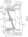
- the cap 206 When the seal 200 is inserted into the entrance 250 of the conduit 935A, 935B, 940A, 940B, the cap 206 abuts the edge 254 of the entrance 250, the edge 254 of the entrance 250 locating in the radial gap 224 between the rim 218 of the seal 200 and the outer tubular wall 204 as best seen in Figure 5 .
- the longitudinal axis 252 of the conduit 935B, 940B is co-axial with the longitudinal axis 208 of the seal 208.
- the outer tubular wall 204 locates inside the entrance 250 and abuts against the inner surface 260 of the entrance of the conduit 935B, 940B.
- the constant radial gap 214 between the two walls 202, 204 remains unaltered when no external force is applied to the inner wall 202 when the seal 200 is located inside the entrance of the conduit 935A, 940B.
- the disk 1015B of the butterfly valve is located inside of the inner tubular wall 202 of the seal 200 inside of the entrance 250 on the conduit 935B, 940B as best seen in Figure 5 .
- Two gaps 262 are formed in the edge 254 of the entrance 250 on opposite sides of the entrance 250 which align with the cut outs 226 of the seal 200 when the seal 200 is inserted into the entrance 250 of the conduit 935B.
- the shaft 1010A on which the disk 1015B is mounted extends through the two gaps 262 and the cut outs 226.
- a solenoid 1002A, 1002B moves the disks 1015A, 1015B between two positions, a first position where it seals the entrance 250 the conduit 935B, 940B (as shown in Figure 5 ) and a second position where the disk 1015A, 1015B is orientated at an angle relative to the entrance 250, opening the entrance 250 of the conduit 935B 940B to allow air (fluid) to pass through the conduit 935B, 940B.
- the disk 1015A, 1015B is in its first position, its periphery engages with and abuts against the inner wall 202 of the seal 200.
- the inner wall 202 flexes radially outwardly, the movement being accommodated by the reduction the size of the radial gap 214 as the inner wall 202 bends.
- the resilient nature of the material of the inner wall 202 of the seal 200 results in the inner wall 202 urging against the periphery of the disk 1015A, 1015B. As such, an airtight seal is produced between the periphery of the disk 1015A, 1015B and the inner wall 202 of the seal 200.
- the solenoid 1002A, 1002B moves the disks 1105B from its first position to its second position, the periphery of the disk 1015A, 1015B disengages from the inner wall 202 of the seal 200.
- the inner wall 202 of the seal reverts to its original shape due to the resilient nature of the material form which the seal 200 is made.
Landscapes
- Engineering & Computer Science (AREA)
- General Engineering & Computer Science (AREA)
- Mechanical Engineering (AREA)
- Lift Valve (AREA)
Abstract
Description
- The present invention relates to a seal for a butterfly valve assembly for a vacuum cleaner, a butterfly valve assembly which comprises a such a seal, and a vacuum cleaner which comprises such a butterfly valve assembly with such a seal.
-
EP2644072 describes a known example (prior art) of a vacuum cleaner. - Referring to
EP2644072 , the vacuum cleaner comprises two valve assemblies formed asbutterfly valves EP2644072 ) which each comprise two circularflat disks rotatable shaft shafts 1010A, 101B about their longitudinal axes results in rotation of thedisks disks shafts disks shaft shaft disks butterfly valve shaft shaft disk shaft 1010A, 101B relative to each other. - Each disk in each pair of
disks valve conduit corresponding conduits shaft 1010A, 1010Bof each valve can be rotated to move the twodisks shaft adjacent conduit disk adjacent conduit conduit conduit disks shaft shaft disk adjacent conduit second disk second disk adjacent conduit - When each
disk adjacent conduit EP2644072 ), the outer periphery of thedisk adjacent conduit disk conduit conduit - Another problem with the valve design disclosed in
EP2644072 is that the entrance of the eachconduit conduit disk conduit disk disk - Accordingly, there is provided a seal in accordance with claim 1.
- Accordingly, there is also provided a butterfly valve assembly in accordance with claim 13 which is capable of using a seal in accordance with any one of claims 1 to 12.
- Accordingly, there is also provided a vacuum cleaner comprising at least one butterfly valve assembly in accordance with any one of claims 13 to 16.
- An example of a prior art design of valve for a vacuum cleaner and an embodiment of the present invention will now be described with reference to the following drawings of which:
-
FIG. 1A illustrates an isolated view of a separator plate of prior art design of vacuum cleaner. -
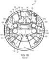
FIG. 1B illustrates a top perspective view of the separator plate shown inFIG. 1A . -
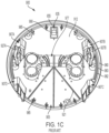
FIG. 1C illustrates a bottom perspective view of the separator plate shown inFIG. 1A . -
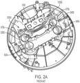
FIG. 2A illustrates a top perspective view of a valve assembly mounted on the separator plate ofFIG. 1A . -
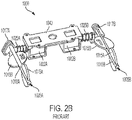
FIG. 2B illustrates an isolated, front perspective view of the valve assembly shown inFIG. 2A . -
FIG. 2C illustrates an isolated, rear perspective view of the valve assembly shown inFIG. 2A . -
FIG. 2D illustrates a cross sectional view of a conduit and a valve of the valve assembly ofFIG. 2A showing the forces acting upon a disc. -
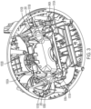
FIG. 3 illustrates a top perspective view of a valve assembly mounted on a separator plate in accordance with the present invention. -
FIG. 4 illustrates a top view of the valve assembly mounted on the separator plate shownFIG. 3 . -
FIG. 5 illustrates a cross sectional view of a conduit with a seal and a valve of the valve assembly ofFIG. 3 . -
FIG 6A shows a perspective view of the seal used in the valve assembly shown inFIG. 3 . -
FIG 6B shows a vertical side cross-sectional view of the seal used in the valve assembly shown inFIG. 3 . -
FIG 6C shows a vertical perspective cross-sectional view of the seal used in the valve assembly shown inFIG. 3 . -
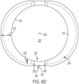
FIG 6D shows a top view of the seal used in the valve assembly shown inFIG. 3 . -
FIG 6E shows a bottom view of the seal used in the valve assembly shown inFIG. 3 . - A prior art design of a valve arrangement in a vacuum cleaner will now be described with reference to
Figures 1A to 1C andFigures 2A to 2D . The description andFigures 1A to 1C andFigures 2A to 2D correspond to the description and Figures 9A to 9C and Figures 10A to 10D ofEP2644072 . The prior art design of valve arrangement in the vacuum cleaner described below with reference toFigures 1A to 1C andFigures 2A to 2D should be understood with reference to the description ofEP2644072 . - Referring to
FIGS. 1A - 1C , aseparator plate 900 engages a tank rim (not shown) of a vacuum cleaner, separating a tank cavity (the collection chamber - not shown) from a cavity (not shown) of a vacuum head (not shown) (also called a motor chamber). Theseparator plate 900 includes a platform 905 (e.g., a generally circulate plate) and one ormore leg members platform 905 includes an upper (head facing)surface 910 and a lower (tank facing)surface 912. The shaped and dimensions of theplatform 905 may be any suitable for its described purpose. By way of example, theplatform 905 may be substantially planar and possess a generally circular shape. Aperimetral wall 915, protruding upward from the platformupper surface 910, extends about the circumference of theplatform 905. As noted above, theupper surface 910 of theplatform 905 may further include one ormore connection posts 917 that engage (e.g., mate, receive, etc.) corresponding connection posts (not shown) extending from the vacuum head. Fasteners may extend through theconnection posts 917 to secure a lid (not shown) to theseparator plate 900. A pair of diametricallyopposed lips 920B extends axially (upward) from theperimetral wall 915 to provide an engagement member for latch devices (not shown). Theplatform 905 may further include one or more reinforcingribs 921 spanning the platformupper surface 910 to enhance the strength of the platform. - The
leg members 907, 907C, extending distally from the platformlower surface 912, are configured to elevate theplatform 905 and, in particular, to suspend a filter system above a supporting surface when the separator is placed directly upon the supporting surface. That is the length of the legs is selected to prevent the filters from contacting the ground when theseparator plate 900 and/or head is removed from the tank and set on a surface. Theleg members - The
leg members separator plate 900 to a tank (not shown) such that the separator plate is oriented in a specific rotational position when inserted into the tank. As shown in the figures, theplatform 905 includes a first forward leg, a secondforward leg 907B, a firstrearward leg 907C, and a second rearward leg. Eachleg proximal leg portion 922 and adistal leg portion 925. Theproximal leg portion 922 of theforward legs 907B includes anotch 927B (e.g., a tapered (V-shaped) notch) configured to receive a guide element (not shown) protruding from an interior surface of the tank. The guide element is positioned at predetermined positions along the tank. Thenotch 927B aligns with each of the tank guide elements such that the first guide element is received within the notch of the first forward leg and the second guide element is received within the notch of the secondforward leg 907B. Consequently, in order for theseparator plate 900 to be inserted into the tank cavity, the notch of first leg member must be aligned with the first guide element and thenotch 927B of thesecond leg member 907B must be aligned with the second guide element. Should the forward (notched)leg members 907B not be aligned with their corresponding guide elements (i.e., should the rotational position of theseparator plate 900 differ from the normal/predetermined position such that no leg or an unnotched leg is aligned with the guide elements), insertion of theseparator plate 900 into the tank cavity of a vacuum cleaner will be prohibited. - The
separator plate 900 further includes a conduit system to enable the flow of air between the tank (the collection chamber) and the head (the motor chamber) of a vacuum cleaner. In the example shown, theplatform 905 of theseparator plate 900 includes a central, raised platform ordeck 902 with a first conduit pair 935 and a second conduit pair 940. The first conduit pair 935 includes a first (forward) suction conduit orport 935A and a first (rearward) cleaning conduit orport 935B. Similarly, the second conduit pair 940 includes a second (forward) suction conduit orport 940A and a second (rearward) cleaning conduit orport 940B. Theconduits conduits - The
conduits conduit suction conduit inboard conduit baffle 942A that curves radially inward with respect to theplatform 905 to direct the air inboard, while the cleaningconduits outboard conduit baffle 942B that curves radially outward to direct air outboard (toward the perimeter of the platform). - The
upper surface 910 of theplatform 905 further includes first 945A, second 945B, and third 945C support walls that cooperate to support the airflow assembly. As shown, thefirst support wall 945A extends upward from theupper surface 910 of theplatform 905, being oriented between thesuction cleaning second support wall 945B is disposed proximate thecleaning conduits third support wall 945C, moreover, is positioned outboard from thesecond support wall 945B. Eachsupport walls 945A - 945C is spaced from its adjacent support wall to define a cavity therebetween. Specifically, the first 945A and second 945B support walls define afan cavity 950 that receives the fan of an airflow assembly. Similarly, the second 945B and third 945C support walls cooperate to define amotor cavity 955 that receives the motor of the airflow assembly. Eachsupport wall section 947 that receives and supports various components of the airflow assembly. By way of example, the second and third support walls cooperate to support a motor of the airflow assembly, with the motor resting within the cut-out section. Themotor cavity 955 further includesareas 957 for supporting valve solenoid switches (discussed in greater detail below). - The
separator plate 900 further includes a pair of opposedmotor intake walls 958 extending from thethird support wall 945C to theperimetral wall 915. Themotor intake walls 958 cooperate with a motor shroud to define a motorair intake area 960 that aligns with second head vent. Similarly, opposedwalls 962 cooperate with the motor shroud to define amotor exhaust area 965 that aligns with a third head vent. - A deflection wall or baffle 970 extends upward from platform upper surface 910 (e.g., the height of the wall may be substantially equal to or greater than the height of the deck 902). The
platform baffle 970 is positioned between thedeck 902 and theperimetral wall 915. Theplatform baffle 970 gradually curves such that it extends from a position along a lateral side of thedeck 902 to a position along the forward side of the deck. Theplatform baffle 970 is operable to direct cooling air exhausted by a manifold toward electronics housed within the head, thereby cooling the electronics. - The
platform 905 further includes afirst yoke 975A located proximate thefirst cleaning conduit 935B and asecond yoke 975B located proximate thesecond cleaning conduit 940B. Eachyoke butterfly valve FIG. 2A ) of the valve assembly to enable rotation of the valve on the yoke (discussed in greater detail below). - The platform
lower surface 912 is best seen inFIG. 1C . As shown, platformlower surface 912 includes a recessedarea 977 generally corresponding with the raiseddeck 902 of the platformupper surface 910. Theperimetral wall 915 of the platformupper surface 910, moreover, defines ashoulder 980 on the platformlower surface 912. Anaxial wall 982 extends downward from thelower surface shoulder 980, being disposed slightly inboard from the circumference of theseparator plate 900. Theaxial wall 982 is wrapped with a generally U-shaped sealing member orgasket 983 configured to contact the rim of the tank of a vacuum cleaner and thereby fluidly seal the joint between the tank rim and theshoulder 980. - A series of downward-extending,
angled fins 985 may be angularly spaced about theplatform 905, being located near the outer edge of the platform, proximate theshoulder 980. Thefins 985 serve as guides during the insertion of theseparator plate 900 into the tank cavity. Abracket 990 is also disposed on the platformlower surface 912 that receives aconductive member 635 of the electrostatic discharge device. As shown, theconductive member 635 is coupled to theplatform 905 via theconductive fastener 655. - A valve assembly, disposed on platform
upper surface 910, opens and closes one or more of theseparator conduits FIGS. 2A - 2C , thevalve assembly 1000 includes afirst solenoid 1002A in communication with to afirst butterfly valve 1005A and asecond solenoid 1002B in communication with to asecond butterfly valve 1005B. Thefirst butterfly valve 1005A is supported by thefirst platform yoke 975A, while the second butterfly valve is supported by thesecond platform yoke 975B. As seen inFIG. 2A , thevalve assembly 1000 is positioned on theseparator plate 900, with eachsolenoid areas 957 as described above. Thesolenoids platform 905 by a cover orbridge 1040 coupled thereto. - The
first butterfly valve 1005A selectively permits airflow through thefirst conduit pair second butterfly valve 1005B selectively permits airflow through thesecond conduit pair butterfly valve elongated shaft distal disc 1015A and a second orproximal disc 1015B longitudinally spaced along the shaft and rotationally offset from the distal disc by, e.g., approximately 45°. - The proximal end of the
shaft arm member pivot pin member plunger solenoid plunger member ski upper surface 910 as theplunger ski plunger solenoid solenoid shaft - As a result, the
valve assembly 1000 may selectively position eachdisc conduit valve assembly 1000 rotationally positions thediscs suction conduits conduits butterfly valve shaft first disc 1015A is oriented generally transverse to the opening defined by thesuction conduit FIG. 2A ), thereby permitting airflow between the tank (the collection chamber) and the head (the motor chamber) of a vacuum cleaner. Thesecond disc 1015B, meanwhile, is positioned such that the disc completely covers the opening of thecleaning conduit valves discs suction conduits conduits - As shown in
FIG. 2D , theconduits discs butterfly valve disc valve disc - An embodiment of the present invention will now be described with reference to
Figures 3 to 6 . The vacuum cleaner in accordance with the present invention is the same as the example of vacuum cleaner described above with reference toFigures 1 and2 except for the design of thebutterfly valves 1005A, 1005B.Thebutterfly valves conduits butterfly valve Figures 1 and2 are present in the embodiment of the present invention, the same reference numbers have been used. - Referring to the
Figures 3 and4 , eachbutterfly valve conduits entrance 250 of one of theconduit butterfly valve seal 200. As best seen inFigure 5 , theedges 254 of theentrances 250 of theconduits seals 200 are perpendicular relative to thelongitudinal axis 252 of theconduit edge 254 of the entrance on all sides being the same height. -
Figures 6A to 6E shows theseal 200. Theseal 200 comprises acap 206 and two concentrictubular side walls longitudinal axis 208 of theseal 200 and which are each connected at a first top end to thecap 206. - The first inner
tubular side wall 202 has a circular cross section in a direction perpendicular to thelongitudinal axis 208, along the length of the first innertubular side wall 202, the size of the cross section being constant and uniform along the length of thewall 202. The first innertubular side wall 202 surrounds thelongitudinal axis 208 in a symmetrical manner. Thethickness 210 ofwall 202 is constant around thelongitudinal axis 208 of theseal 200 and along the length of thewall 202. - The second outer
tubular side wall 204 has a circular cross section in a direction perpendicular to thelongitudinal axis 208, along the length of the second outertubular side wall 204, the size of the cross section being constant and uniform along the length of thewall 204. The second outertubular side wall 204 surrounds thelongitudinal axis 208 in a symmetrical manner. Thethickness 212 ofwall 204 is constant around thelongitudinal axis 208 of theseal 200 and along the length of thewall 204. - The second outer
tubular wall 204 surrounds the first innertubular wall 202 in a concentric and symmetrical manner so that a constantradial gap 214 is formed between the twowalls longitudinal axis 208 of theseal 200 and along the length of thewalls thickness 212 of the second outertubular wall 204 is the same as that of the first innertubular wall 202. The length of the second outertubular wall 204 is slightly less than that of the first innertubular wall 202. - The
cap 206 comprises anannular base 216 and an outer ring shapedrim 218 connected to outer periphery of theannular base 216 and which extends perpendicularly to the annular base 216.The twotubular walls annular base 216. The firstinner wall 202 attaches to theannular base 216 adjacent theinner edge 222 of theannular base 216 in order to form atubular passage 220 of uniform circular cross section through the whole length of theinner wall 202 and theannular base 216. The second outertubular wall 204 connects to the underside ofannular base 216 between therim 218 and the innertubular wall 202. Therim 218 extends in parallel to the twotubular walls tubular walls 202 in a concentric and symmetrical manner so that a constantradial gap 224 is formed between therim 218 and the outertubular wall 204. Thethickness 226 of therim 218 is slightly larger than that of the twotubular walls annular base 216. - Two cut outs 226 (as best seen in
Figure 6A ) are formed through therim 218 and theannular base 216 of the cap206, and the twotubular side walls seal 200, in a symmetrical manner. Each cut out 226 comprises twostraight sides 228, which extend in a direction parallel to thelongitudinal axis 208 of theseal 200, and asemi-circular side 230 which interconnects between the twostraight sides 228. A bridgingwall 232 connects between the outertubular side wall 204 and innertubular side wall 202 along the twostraight sides 228 and thesemi-circular side 230 to enclose theradial gap 214. Thelength 234 of therim 218 on either side of thecut outs 226 is shorter than thelength 236 of therim 218 around the rest of theannular base 216. Thewidth 238 of theannular base 216 on either side of thecut outs 226 is slightly less than thewidth 240 of theannular base 216 around the rest of theannular base 216. - The seal (200) is made in a one-piece construction from resiliently deformable rubber material. However, it will be appreciated that the seal could be made from a plurality of components. Regardless of whether the seal is made in a one-piece construction or a plurality of components, so long as the inner
tubular side wall 202 is made from resiliently deformable material, the seal can function. - When the
seal 200 is inserted into theentrance 250 of theconduit cap 206 abuts theedge 254 of theentrance 250, theedge 254 of theentrance 250 locating in theradial gap 224 between therim 218 of theseal 200 and the outertubular wall 204 as best seen inFigure 5 . When the seal is located in theentrance 250, thelongitudinal axis 252 of theconduit longitudinal axis 208 of theseal 208. The outertubular wall 204 locates inside theentrance 250 and abuts against theinner surface 260 of the entrance of theconduit radial gap 214 between the twowalls inner wall 202 when theseal 200 is located inside the entrance of theconduit - The
disk 1015B of the butterfly valve is located inside of the innertubular wall 202 of theseal 200 inside of theentrance 250 on theconduit Figure 5 . Twogaps 262 are formed in theedge 254 of theentrance 250 on opposite sides of theentrance 250 which align with thecut outs 226 of theseal 200 when theseal 200 is inserted into theentrance 250 of theconduit 935B. Theshaft 1010A on which thedisk 1015B is mounted extends through the twogaps 262 and thecut outs 226. Asolenoid disks entrance 250 theconduit Figure 5 ) and a second position where thedisk entrance 250, opening theentrance 250 of theconduit 935Bconduit disk inner wall 202 of theseal 200. As thedisk inner wall 202 by thesolenoid inner wall 202 flexes radially outwardly, the movement being accommodated by the reduction the size of theradial gap 214 as theinner wall 202 bends. The resilient nature of the material of theinner wall 202 of theseal 200 results in theinner wall 202 urging against the periphery of thedisk disk inner wall 202 of theseal 200. When thesolenoid disk inner wall 202 of theseal 200. Theinner wall 202 of the seal reverts to its original shape due to the resilient nature of the material form which theseal 200 is made.
Claims (16)
- A seal for a butterfly valve assembly comprising:an end cap (206)an inner tubular side wall (202) attached at one end to the end cap (206);an outer tubular side wall (204) attached at one end to the end cap (206) and which surrounds the inner tubular side wall (202) and extends in the same direction as the inner tubular side wall (202) to provide a gap (214) between the inner tubular side wall (202) and outer tubular side wall (204);wherein at least the inner tubular side wall (202) is made from a resiliently deformable material.
- A seal as claimed in claim 1 wherein:1) the inner tubular side wall (202) is circular in cross- section, in a direction perpendicular to a longitudinal axis (208) of the seal (200), along the length of the inner tubular side wall (202); and/or2) the outer tubular side wall (204) is circular in cross- section, in a direction perpendicular to a longitudinal axis (208) of the seal (200), along the length of the outer tubular side wall (204).
- A seal as claimed in either of claims 1 or 2 wherein:1) the thickness (212) of the inner tubular side wall (202) is constant; and/or2) the thickness (214) of the outer tubular side wall (204) is constant.
- A seal as claimed in any of the previous claims wherein inner the tubular side wall (202) and the outer tubular side wall (204) are concentric around a longitudinal axis (208) to form a radial gap (214) of constant thickness.
- A seal as claimed in any of the previous claims wherein the end cap (206) comprises an annular base (216) and a rim (218) attached to the annular base (216);
wherein the inner tubular side wall (202) attached at one end to the annular base (216) and the outer tubular side wall (204) is attached at one end to the annular base (216). - A seal as claimed in claim 5 wherein the inner tubular side wall (202) attaches to the annular base (206) adjacent the inner edge (222) of the annular base (206) in order to form a tubular passage (220) of uniform circular cross section through the whole length of the inner wall (202) and the annular base (206).
- A seal as claimed in either of claims 5 or 6 wherein the rim (218) surrounds the outer tubular side wall (204) to provide a gap (224) between the rim (218) and the outer tubular side wall (204).
- A seal as claimed in any of claims 5 to 7 wherein the rim (218) is attached to the outer periphery of the annular base (216).
- A seal as claimed in any of claims 5 to 8 wherein the rim (218) and the outer tubular side wall (204) are concentric around a longitudinal axis (208) to form a radial gap (224) of constant thickness.
- A seal as claimed in any one of the previous claims wherein at least one cut out (226) is formed through the end cap (206), the inner tubular side wall (202) and the outer tubular side wall (204).
- A seal as claimed in any of claims 5 to 10 wherein at least one cut out (226) is formed through at least the annular base (216), the inner tubular side wall (202), the outer tubular side wall (204) and the rim (218).
- A seal as claimed in any of the previous claims wherein:1) at least the inner tubular side wall (202) and preferably the whole of the seal is made from a resiliently deformable material; and/or2) at least the inner tubular side wall (202) and preferable the whole of the seal is made from rubber.
- A butterfly valve assembly comprising:at least one conduit (935A, 935B, 940A, 940B) having an entrance (250) through which a fluid can pass;a seal (200) as claimed in any one of claims 1 to 12 mounted in the entrance (250) of the conduit (935A, 935B, 940A, 940B) so that the end cap (206) abuts against an edge (254) of the entrance (250) and the inner tubular side wall (202) and outer tubular side wall (204) extend into the entrance (250) the outer tubular wall (204) abutting against an inner surface (260) of the entrance of the conduit (935A, 935B, 940A, 940B);a rotatable pivotal disk (1015A, 1015B) mounted inside the inner tubular side wall (202) of the seal (200) within the entrance (250) which can be rotated between a first position where the periphery of the disk (1015A, 1015B) engages the inner tubular side wall (202) of the seal (200) to seal the entrance (250) of the conduit (935A, 935B, 940A, 940B) and a second position where the disk (1015A, 1015B) is orientated at an angle relative to the entrance (250) of the conduit (935A, 935B, 940A, 940B), to disengage the periphery of the disk (1015A, 1015B) from the inner wall (202) in order to open the entrance and allow the fluid to pass through the conduit (935A, 935B, 940A, 940B).
- A butterfly valve assembly as claimed in claim 13 wherein the conduit (935A, 935B, 940A, 940B) comprises a longitudinal axis (252);
wherein the edge (254) of the entrance (250) of the conduit (935A, 935B, 940A 940B) is perpendicular relative to the longitudinal axis (252) of the conduit (935A, 935B, 940A, 940B). - A butterfly valve assembly as claimed in either of claims 13 or 14 when dependent on claim 9 wherein the edge (254) of the entrance (250) locates in the gap (224) between the rim (218) and the outer tubular side wall (204) of the seal (200).
- A butterfly valve assembly as claimed in any of claims 13 to 15 when dependent on either of claims 10 or 11 wherein the edge comprises at least one gap (262);wherein the cut out (226) of the seal (200) is aligned with the gap (262) of the edge when the seal is mounted in the entrance of the conduit;wherein the disk is mounted on a rotatable shaft, wherein the shaft extends from the entrance through the cut out and the gap.
Applications Claiming Priority (1)
| Application Number | Priority Date | Filing Date | Title |
|---|---|---|---|
| GB2112532.3A GB2610406A (en) | 2021-09-02 | 2021-09-02 | Seal |
Publications (1)
| Publication Number | Publication Date |
|---|---|
| EP4145026A1 true EP4145026A1 (en) | 2023-03-08 |
Family
ID=78076701
Family Applications (1)
| Application Number | Title | Priority Date | Filing Date |
|---|---|---|---|
| EP22192097.8A Pending EP4145026A1 (en) | 2021-09-02 | 2022-08-25 | Seal |
Country Status (3)
| Country | Link |
|---|---|
| US (1) | US11927269B2 (en) |
| EP (1) | EP4145026A1 (en) |
| GB (1) | GB2610406A (en) |
Citations (3)
| Publication number | Priority date | Publication date | Assignee | Title |
|---|---|---|---|---|
| US20070084437A1 (en) * | 2005-10-07 | 2007-04-19 | Hugues Winkelmuller | Valve regulating device and intake manifold comprising at least one such device |
| EP2644072A2 (en) | 2012-03-27 | 2013-10-02 | Black & Decker Inc. | Wet and dry vacuum cleaner |
| US20170299065A1 (en) * | 2014-10-07 | 2017-10-19 | Kitz Corporation | Butterfly-valve seat ring and fixing structure of the same, and eccentric-type butterfly valve |
Family Cites Families (13)
| Publication number | Priority date | Publication date | Assignee | Title |
|---|---|---|---|---|
| US4210313A (en) * | 1973-08-03 | 1980-07-01 | Litton Industrial Products, Inc. | Pressure actuated resilient valve seal |
| JPS6030872B2 (en) | 1976-05-26 | 1985-07-18 | 甲南電機株式会社 | 5-port 3-position center closed type switching valve |
| JPS6030872A (en) * | 1983-07-27 | 1985-02-16 | Kubota Ltd | butterfly valve |
| JP4394337B2 (en) | 2002-08-29 | 2010-01-06 | 株式会社デンソー | Throttle valve device for internal combustion engine |
| JP4376017B2 (en) | 2003-08-01 | 2009-12-02 | 株式会社デンソー | Electronically controlled throttle control device |
| JP2005054627A (en) | 2003-08-01 | 2005-03-03 | Denso Corp | Throttle body |
| CN103589075B (en) | 2008-07-11 | 2015-08-19 | 日信工业株式会社 | Pipeline material sealing member and manufacture method thereof and pipeline material |
| KR101096525B1 (en) * | 2011-04-26 | 2011-12-20 | 서광공업 주식회사 | Butterfly valves maintain sealing performance at low and high temperatures |
| DE102011114573B4 (en) | 2011-09-30 | 2014-02-27 | Sartorius Stedim Biotech Gmbh | Valve device and method for transferring a transfer medium |
| JP6698419B2 (en) | 2016-05-06 | 2020-05-27 | 愛三工業株式会社 | Exhaust gas recirculation valve |
| CN212226008U (en) | 2020-03-24 | 2020-12-25 | 浙江捷升阀门制造有限公司 | Butterfly valve |
| CN212718042U (en) | 2020-07-13 | 2021-03-16 | 安徽高中压阀门科技有限公司 | Convenient anti-blocking butterfly valve who overhauls |
| KR102219379B1 (en) * | 2020-12-24 | 2021-02-22 | 최준영 | Butterfly valve |
-
2021
- 2021-09-02 GB GB2112532.3A patent/GB2610406A/en not_active Withdrawn
-
2022
- 2022-08-25 EP EP22192097.8A patent/EP4145026A1/en active Pending
- 2022-08-31 US US17/899,844 patent/US11927269B2/en active Active
Patent Citations (3)
| Publication number | Priority date | Publication date | Assignee | Title |
|---|---|---|---|---|
| US20070084437A1 (en) * | 2005-10-07 | 2007-04-19 | Hugues Winkelmuller | Valve regulating device and intake manifold comprising at least one such device |
| EP2644072A2 (en) | 2012-03-27 | 2013-10-02 | Black & Decker Inc. | Wet and dry vacuum cleaner |
| US20170299065A1 (en) * | 2014-10-07 | 2017-10-19 | Kitz Corporation | Butterfly-valve seat ring and fixing structure of the same, and eccentric-type butterfly valve |
Also Published As
| Publication number | Publication date |
|---|---|
| GB202112532D0 (en) | 2021-10-20 |
| US11927269B2 (en) | 2024-03-12 |
| GB2610406A (en) | 2023-03-08 |
| US20230066687A1 (en) | 2023-03-02 |
Similar Documents
| Publication | Publication Date | Title |
|---|---|---|
| US7797791B2 (en) | Vacuum with panel filter | |
| US12133613B2 (en) | Vacuum food processing system | |
| US5660493A (en) | Latch assembly for blower of wet/dry vacuum cleaner | |
| CN212939453U (en) | Food processing systems, container assemblies therefor and accessories used therewith | |
| CN1425109A (en) | Pump having dynamic shaft seal | |
| KR20090012341A (en) | Air exhaust | |
| EP4711653A1 (en) | Valve | |
| CN222565756U (en) | Negative pressure suction valve and endoscope | |
| WO2010056046A2 (en) | Check valve for vacuum packaging | |
| GB2610406A (en) | Seal | |
| US12213627B2 (en) | Food processor | |
| US6508637B2 (en) | Air compressor | |
| CN113712428B (en) | Cooking utensil and pot cover thereof | |
| FR2762805A1 (en) | HEATING-AIR CONDITIONING DEVICE FOR A MOTOR VEHICLE, WITH MOTOR-FAN GROUP WITH INTEGRATED EXTRACTIBLE AIR FILTER | |
| EP2353694A1 (en) | Filter element, filter installation provided with such a filter element, and connecting plate and flange for use in such a filter installation | |
| CN222486931U (en) | Cup cover assembly and vacuum cup | |
| EP1174071A2 (en) | Pump inlet fitting | |
| CN224219874U (en) | Rotary cup cover | |
| CN218922358U (en) | Slurry discharging structure and wall breaking machine | |
| CN112638217A (en) | Stirrer system with vibration-proof seal | |
| US20260132778A1 (en) | Vacuum Extractor Device | |
| JPH04327815A (en) | vacuum cleaner | |
| CN121015069A (en) | A vacuum cleaner | |
| KR20240023876A (en) | Test tube used in the centrifugal separator | |
| KR20230139426A (en) | Dust collector of vacuum cleaner |
Legal Events
| Date | Code | Title | Description |
|---|---|---|---|
| PUAI | Public reference made under article 153(3) epc to a published international application that has entered the european phase |
Free format text: ORIGINAL CODE: 0009012 |
|
| STAA | Information on the status of an ep patent application or granted ep patent |
Free format text: STATUS: THE APPLICATION HAS BEEN PUBLISHED |
|
| AK | Designated contracting states |
Kind code of ref document: A1 Designated state(s): AL AT BE BG CH CY CZ DE DK EE ES FI FR GB GR HR HU IE IS IT LI LT LU LV MC MK MT NL NO PL PT RO RS SE SI SK SM TR |
|
| STAA | Information on the status of an ep patent application or granted ep patent |
Free format text: STATUS: REQUEST FOR EXAMINATION WAS MADE |
|
| 17P | Request for examination filed |
Effective date: 20230317 |
|
| RBV | Designated contracting states (corrected) |
Designated state(s): AL AT BE BG CH CY CZ DE DK EE ES FI FR GB GR HR HU IE IS IT LI LT LU LV MC MK MT NL NO PL PT RO RS SE SI SK SM TR |
|
| STAA | Information on the status of an ep patent application or granted ep patent |
Free format text: STATUS: EXAMINATION IS IN PROGRESS |
|
| 17Q | First examination report despatched |
Effective date: 20250606 |