EP4144968A1 - Control device for a supercharged engine provided with two exhaust valves per cylinder - Google Patents
Control device for a supercharged engine provided with two exhaust valves per cylinder Download PDFInfo
- Publication number
- EP4144968A1 EP4144968A1 EP22187742.6A EP22187742A EP4144968A1 EP 4144968 A1 EP4144968 A1 EP 4144968A1 EP 22187742 A EP22187742 A EP 22187742A EP 4144968 A1 EP4144968 A1 EP 4144968A1
- Authority
- EP
- European Patent Office
- Prior art keywords
- exhaust
- valve
- cam
- engine
- switching
- Prior art date
- Legal status (The legal status is an assumption and is not a legal conclusion. Google has not performed a legal analysis and makes no representation as to the accuracy of the status listed.)
- Granted
Links
Images



Classifications
-
- F—MECHANICAL ENGINEERING; LIGHTING; HEATING; WEAPONS; BLASTING
- F02—COMBUSTION ENGINES; HOT-GAS OR COMBUSTION-PRODUCT ENGINE PLANTS
- F02B—INTERNAL-COMBUSTION PISTON ENGINES; COMBUSTION ENGINES IN GENERAL
- F02B37/00—Engines characterised by provision of pumps driven at least for part of the time by exhaust
- F02B37/12—Control of the pumps
- F02B37/18—Control of the pumps by bypassing exhaust from the inlet to the outlet of turbine or to the atmosphere
- F02B37/183—Arrangements of bypass valves or actuators therefor
-
- F—MECHANICAL ENGINEERING; LIGHTING; HEATING; WEAPONS; BLASTING
- F01—MACHINES OR ENGINES IN GENERAL; ENGINE PLANTS IN GENERAL; STEAM ENGINES
- F01L—CYCLICALLY OPERATING VALVES FOR MACHINES OR ENGINES
- F01L13/00—Modifications of valve-gear to facilitate reversing, braking, starting, changing compression ratio, or other specific operations
- F01L13/0015—Modifications of valve-gear to facilitate reversing, braking, starting, changing compression ratio, or other specific operations for optimising engine performances by modifying valve lift according to various working parameters, e.g. rotational speed, load, torque
-
- F—MECHANICAL ENGINEERING; LIGHTING; HEATING; WEAPONS; BLASTING
- F01—MACHINES OR ENGINES IN GENERAL; ENGINE PLANTS IN GENERAL; STEAM ENGINES
- F01L—CYCLICALLY OPERATING VALVES FOR MACHINES OR ENGINES
- F01L13/00—Modifications of valve-gear to facilitate reversing, braking, starting, changing compression ratio, or other specific operations
- F01L13/0015—Modifications of valve-gear to facilitate reversing, braking, starting, changing compression ratio, or other specific operations for optimising engine performances by modifying valve lift according to various working parameters, e.g. rotational speed, load, torque
- F01L13/0036—Modifications of valve-gear to facilitate reversing, braking, starting, changing compression ratio, or other specific operations for optimising engine performances by modifying valve lift according to various working parameters, e.g. rotational speed, load, torque the valves being driven by two or more cams with different shape, size or timing or a single cam profiled in axial and radial direction
-
- F—MECHANICAL ENGINEERING; LIGHTING; HEATING; WEAPONS; BLASTING
- F02—COMBUSTION ENGINES; HOT-GAS OR COMBUSTION-PRODUCT ENGINE PLANTS
- F02B—INTERNAL-COMBUSTION PISTON ENGINES; COMBUSTION ENGINES IN GENERAL
- F02B37/00—Engines characterised by provision of pumps driven at least for part of the time by exhaust
- F02B37/02—Gas passages between engine outlet and pump drive, e.g. reservoirs
-
- F—MECHANICAL ENGINEERING; LIGHTING; HEATING; WEAPONS; BLASTING
- F02—COMBUSTION ENGINES; HOT-GAS OR COMBUSTION-PRODUCT ENGINE PLANTS
- F02B—INTERNAL-COMBUSTION PISTON ENGINES; COMBUSTION ENGINES IN GENERAL
- F02B37/00—Engines characterised by provision of pumps driven at least for part of the time by exhaust
- F02B37/12—Control of the pumps
- F02B37/22—Control of the pumps by varying cross-section of exhaust passages or air passages, e.g. by throttling turbine inlets or outlets or by varying effective number of guide conduits
-
- F—MECHANICAL ENGINEERING; LIGHTING; HEATING; WEAPONS; BLASTING
- F02—COMBUSTION ENGINES; HOT-GAS OR COMBUSTION-PRODUCT ENGINE PLANTS
- F02D—CONTROLLING COMBUSTION ENGINES
- F02D13/00—Controlling the engine output power by varying inlet or exhaust valve operating characteristics, e.g. timing
- F02D13/02—Controlling the engine output power by varying inlet or exhaust valve operating characteristics, e.g. timing during engine operation
- F02D13/0242—Variable control of the exhaust valves only
- F02D13/0246—Variable control of the exhaust valves only changing valve lift or valve lift and timing
-
- F—MECHANICAL ENGINEERING; LIGHTING; HEATING; WEAPONS; BLASTING
- F02—COMBUSTION ENGINES; HOT-GAS OR COMBUSTION-PRODUCT ENGINE PLANTS
- F02D—CONTROLLING COMBUSTION ENGINES
- F02D13/00—Controlling the engine output power by varying inlet or exhaust valve operating characteristics, e.g. timing
- F02D13/02—Controlling the engine output power by varying inlet or exhaust valve operating characteristics, e.g. timing during engine operation
- F02D13/0257—Independent control of two or more intake or exhaust valves respectively, i.e. one of two intake valves remains closed or is opened partially while the other is fully opened
-
- F—MECHANICAL ENGINEERING; LIGHTING; HEATING; WEAPONS; BLASTING
- F02—COMBUSTION ENGINES; HOT-GAS OR COMBUSTION-PRODUCT ENGINE PLANTS
- F02D—CONTROLLING COMBUSTION ENGINES
- F02D41/00—Electrical control of supply of combustible mixture or its constituents
- F02D41/0002—Controlling intake air
- F02D41/0007—Controlling intake air for control of turbo-charged or super-charged engines
-
- F—MECHANICAL ENGINEERING; LIGHTING; HEATING; WEAPONS; BLASTING
- F02—COMBUSTION ENGINES; HOT-GAS OR COMBUSTION-PRODUCT ENGINE PLANTS
- F02D—CONTROLLING COMBUSTION ENGINES
- F02D41/00—Electrical control of supply of combustible mixture or its constituents
- F02D41/0002—Controlling intake air
- F02D2041/001—Controlling intake air for engines with variable valve actuation
-
- F—MECHANICAL ENGINEERING; LIGHTING; HEATING; WEAPONS; BLASTING
- F02—COMBUSTION ENGINES; HOT-GAS OR COMBUSTION-PRODUCT ENGINE PLANTS
- F02D—CONTROLLING COMBUSTION ENGINES
- F02D2200/00—Input parameters for engine control
- F02D2200/02—Input parameters for engine control the parameters being related to the engine
- F02D2200/04—Engine intake system parameters
- F02D2200/0406—Intake manifold pressure
-
- F—MECHANICAL ENGINEERING; LIGHTING; HEATING; WEAPONS; BLASTING
- F02—COMBUSTION ENGINES; HOT-GAS OR COMBUSTION-PRODUCT ENGINE PLANTS
- F02D—CONTROLLING COMBUSTION ENGINES
- F02D2200/00—Input parameters for engine control
- F02D2200/02—Input parameters for engine control the parameters being related to the engine
- F02D2200/10—Parameters related to the engine output, e.g. engine torque or engine speed
- F02D2200/101—Engine speed
-
- Y—GENERAL TAGGING OF NEW TECHNOLOGICAL DEVELOPMENTS; GENERAL TAGGING OF CROSS-SECTIONAL TECHNOLOGIES SPANNING OVER SEVERAL SECTIONS OF THE IPC; TECHNICAL SUBJECTS COVERED BY FORMER USPC CROSS-REFERENCE ART COLLECTIONS [XRACs] AND DIGESTS
- Y02—TECHNOLOGIES OR APPLICATIONS FOR MITIGATION OR ADAPTATION AGAINST CLIMATE CHANGE
- Y02T—CLIMATE CHANGE MITIGATION TECHNOLOGIES RELATED TO TRANSPORTATION
- Y02T10/00—Road transport of goods or passengers
- Y02T10/10—Internal combustion engine [ICE] based vehicles
- Y02T10/12—Improving ICE efficiencies
Definitions
- the technique disclosed herein relates to a control device for an engine.
- Patent Literature 1 discloses, as one example of an engine using a blowdown supercharging system, an engine that, in each combustion chamber, includes plural exhaust ports which communicate with exhaust passages independent from each other and plural exhaust valves which are disposed to the respective exhaust ports and whose valve-opening time points are different from each other.
- the gas passage is composed of a first exhaust passage which communicates with a first exhaust valve opening in an early period and in which a turbine of a turbosupercharger is disposed and a second exhaust passage which communicates with a second exhaust valve opening at a time point later than the first exhaust valve and is united with the first exhaust passage while circumventing the turbine.
- high-pressure exhaust gas jetted out in response to opening of the first exhaust valve rotates the turbine from an end period of an expansion stroke to an intermediate period of an exhaust stroke. Meanwhile, from the intermediate period to an end period of the exhaust stroke, the exhaust gas which has not completely been exhausted through the first exhaust valve is exhausted in response to opening of the second exhaust valve while circumventing or bypassing the turbine.
- the second exhaust passage is not connected with the turbine.
- the second exhaust passage is at a lower pressure than the first exhaust passage. Accordingly, pump loss (hereinafter, also referred to as "discharge loss") of the second exhaust valve is reduced.
- discharge loss pump loss
- exhaust gas in a cylinder is exhausted with low pump loss.
- Patent Literature 1 Japanese Patent Laid-Open No. 11-210449
- the inventors of the present application intensively analyzed factors of the newly found tendency. As a result, it has become clear that an increase in an exhaust resistance due to a second exhaust valve is a main factor. That is, because a combustion frequency per predetermined time is higher in a higher rotation range, a total amount of exhaust gas becomes more. Because the area of the second exhaust valve is limited, more pumping work is needed for exhausting a large amount of exhaust gas.
- the technique disclosed herein has been made in consideration of such points, and an object thereof is to reduce an increase in pump loss in a high rotation range.
- a first aspect of the present disclosure relates to a control device for an engine, the control device including: a first exhaust port and a second exhaust port which open in each cylinder of the engine; a first exhaust valve which opens and closes the first exhaust port; a second exhaust valve which opens and closes the second exhaust port; an exhaust valve mechanism which is configured to open the first exhaust valve at least at an earlier time point than an initial period of an exhaust stroke and to meanwhile open the second exhaust valve at a later time point than the first exhaust valve; an exhaust passage which is connected with the first exhaust port and the second exhaust port; and a supercharger (or a turbocharger) which is composed of a turbine provided to the exhaust passage and a compressor provided to an intake passage of the engine.
- the exhaust valve mechanism is configured to open the first exhaust valve earlier than the exhaust stroke and to open the second exhaust valve later than the first exhaust valve.
- the exhaust passage has a first exhaust passage which is connected with the first exhaust port and in which the turbine is arranged, a second exhaust passage which is connected with the second exhaust port and merges with the first exhaust passage while circumventing the turbine, and a third exhaust passage which connects the first exhaust passage on an upstream side of the turbine with the second exhaust passage.
- control device for an engine further includes: a first switching valve which is arranged in the third exhaust passage and changes a channel area (or an open area) of the third exhaust passage; a second switching valve which is arranged in the second exhaust passage on a downstream side of a connection portion with the third exhaust passage and on an upstream side of a merging portion with the first exhaust passage and which changes a channel area of the second exhaust passage; a rotational speed sensor which detects an engine speed; and a controller which controls opening and closing of the first switching valve and the second switching valve based on a detection signal by the rotational speed sensor, and the controller controls the first switching valve and the second switching valve to close the first switching valve and open the second switching valve in a case where the engine speed is lower than a predetermined first rotational speed and to open the first switching valve and close the second switching valve in a case where the engine speed is higher than the first rotational speed.
- a term of "closing a valve” includes a relatively closing state to a fully open state. What is meant by this term is not limited to a fully closed state.
- an opening of the second switching valve may be set to the fully closed state or a closing side compared to the fully open state. The same applies to a term of "opening a valve”.
- the controller closes the first switching valve and opens the second switching valve in a low rotation range, thereby causes the first exhaust passage to be connected with the turbine, and causes the second exhaust passage not to be connected with the turbine.
- high-energy exhaust gas exhausted by early opening of the first exhaust valve passes through the turbine via the first exhaust passage.
- the exhaust gas exhausted by opening of the second exhaust valve which is conducted later than the first exhaust valve circumvents the turbine via the second exhaust passage. Because the second exhaust passage is at a relatively low pressure, lower pump loss of the second exhaust valve can be realized.
- the controller opens the first switching valve and closes the second switching valve.
- the first exhaust passage is connected with the turbine, and further the second exhaust passage is also connected with the turbine via the third exhaust passage and the first exhaust passage.
- the exhaust gas exhausted by opening of the second exhaust valve is guided to the turbine via the first exhaust passage similarly to the exhaust gas related to the first exhaust valve. Accordingly, because the supercharging pressure can further be made higher, lower pump loss of an intake valve (lowering of intake loss) can be realized. As a result, even in a high rotation range, it becomes possible to reduce an increase in the pump loss for the whole engine.
- the first rotational speed may be set low compared to a case where the load is low.
- the first rotational speed is set or becomes lower as the load becomes higher.
- the relationship of "engine speed ⁇ first rotational speed" is satisfied even with a higher load, and a blowdown supercharging system is conducted.
- the blowdown supercharging system because there is concern about an increase in the pump loss on a high rotation side, such a setting is advantageous in maximizing fuel efficiency.
- the controller may set an opening of the second switching valve to a closing side compared to a fully open state in a case where the engine speed is higher than the first rotational speed and may adjust the opening of the second switching valve such that the channel area of the second exhaust passage becomes large in a case where the load on the engine is high compared to a case where the load is low.
- the controller may set an opening of the second switching valve to be smaller than a fully open state in a case where the engine speed is higher than the first rotational speed and may control the second switching valve to open more as the load on the engine becomes higher.
- the controller guides a part of the exhaust gas exhausted by opening of the second exhaust valve to the turbine but causes the remaining exhaust gas to circumvent the turbine.
- An exhaust gas amount guided to the turbine is controlled through the opening adjustment of the second switching valve. Consequently, the second switching valve can be utilized as a so-called wastegate valve, and further the supercharging pressure can be stabilized.
- the control device for an engine may further include an exhaust valve mechanism which drives the first exhaust valve and the second exhaust valve
- the exhaust valve mechanism may have a first cam set composed of a first cam profile which opens the first exhaust valve at least at an earlier time point than the initial period of the exhaust stroke and a second cam profile which opens the second exhaust valve at a later time point than the first exhaust valve, a second cam set composed of a pair of third cam profiles whose valve-opening angles are set larger than the first cam profile and the second cam profile and which open the first exhaust valve and the second exhaust valve, and a cam switching unit which performs switching to the first cam set or the second cam set
- the controller may be configured to control switching by the cam switching unit based on the detection signal by the rotational speed sensor, and the controller may control the cam switching unit to open and close the first exhaust valve and the second exhaust valve by the first cam set in a case where the engine speed is lower than the first rotational speed and to open and close the first exhaust valve and the second exhaust valve by the second cam
- the cam switching unit may switch the first cam set and the second cam set.
- the cam switching unit may perform switching to the first cam set from the second cam set, and/or switching to the second cam set from the first cam set.
- the controller opens and closes the first and second exhaust valves by the first cam set on a low rotation side but opens and closes the first and second exhaust valves by the second cam set on a high rotation side.
- the third cam profiles constituting the second cam set have larger valve-opening angles than the first and second cam profiles constituting the first cam set.
- the first cam profile may set a valve-opening time point of the first exhaust valve to an intermediate period of a combustion stroke of the engine and may set a valve-closing time point of the first exhaust valve to fall within a period from the initial period to an intermediate period of the exhaust stroke of the engine.
- an intermediate period of a combustion stroke indicates an intermediate period in a case where the combustion stroke is divided into three generally equal parts of an initial period, an intermediate period, and an end period.
- an initial period of an exhaust stroke indicates an initial period in a case where the exhaust stroke is divided into three generally equal parts of an initial period, an intermediate period, and an end period.
- the valve-opening time point of the first exhaust valve is set to the intermediate period of the combustion stroke. Accordingly, for example, compared to a case where the valve opening time point is set to the end period of the combustion stroke, the valve-opening angle can be set large, and valve acceleration can be reduced. Accordingly, while the lift amount is made as large as possible, an occurrence of valve jump can be inhibited. Further, when the valve-opening time point is set to the intermediate period of the combustion stroke, this is also advantageous in reduction in influence on combustion torque compared to a case where the valve-opening time point is set to the initial period of the combustion stroke, for example.
- the second cam profile may set a valve-opening time point of the second exhaust valve to the end period of the combustion stroke of the engine and may set a valve-closing time point of the second exhaust valve to fall within a period from an end period of the exhaust stroke to an initial period of an intake stroke of the engine.
- an end period of a combustion stroke indicates an end period in a case where the combustion stroke is divided into three generally equal parts of an initial period, an intermediate period, and an end period.
- an end period of an exhaust stroke indicates an end period in a case where the exhaust stroke is divided into three generally equal parts of an initial period, an intermediate period, and an end period.
- An initial period of an intake stroke indicates an initial period in a case where the intake stroke is divided into three generally equal parts of an initial period, an intermediate period, and an end period.
- the valve-opening time point of the second exhaust valve is set to the end period of the combustion stroke. Accordingly, for example, compared to a case where the valve opening time point is set to the initial period of the exhaust stroke, the valve-opening angle can be set large, and the valve acceleration can be reduced. Consequently, while the lift amount is made as large as possible, an occurrence of the valve jump can be inhibited.
- the first cam profile may set a lift amount of the first exhaust valve smaller than a lift amount of the first exhaust valve by the third cam profile and a lift amount of the second exhaust valve by the second cam profile
- the second cam profile may set a lift amount of the second exhaust valve smaller than a lift amount of the second exhaust valve by the third cam profile
- the second exhaust valve acts at a high speed on a high rotation side
- the second cam profile is not used on a high rotation side, the lift amount can be made larger than related art.
- the second cam profile according to the seventh aspect sets the lift amount of the second exhaust valve relatively larger than the lift amount of the first exhaust valve by the first cam profile. Accordingly, the exhaust gas amount which circumvents the turbine can sufficiently be secured, and this further becomes advantageous in reduction in the discharge loss of the second exhaust valve.
- the lift amount of the second exhaust valve by the second cam profile is set relatively smaller than the lift amount of the second exhaust valve by the third cam profile, and an occurrence of the valve jump can thereby more certainly be inhibited.
- an operation region of the engine may include a first region on a lower rotation side of the first rotational speed and a second region on a higher rotation side of the first rotational speed
- the controller may be configured to cause a timing when the first switching valve is opened and the second switching valve is closed and a timing when switching is made from the first cam set to the second cam set to be different from each other in transition from the first region to the second region.
- Both of opening the first switching valve and opening the second switching valve and switching from the first cam set to the second cam set cause an increase in the supercharging pressure.
- a rapid increase in the supercharging pressure is caused.
- a rapid increase in the supercharging pressure causes a torque shock and further degradation of drivability and may thus result in inconvenience.
- the controller according to the eighth aspect causes the timing when open-closed states of the first and second switching valves are switched and the timing when switching is made from the first cam set to the second cam set to be different from each other. Accordingly, the supercharging pressure can be caused to smoothly rise. Accordingly, a rapid change in the supercharging pressure can be inhibited, and further drivability can be kept proper.
- the control device for an engine may further include a supercharging pressure sensor which detects a supercharging pressure of the supercharger, the controller may set a target supercharging pressure in accordance with an operation state of the engine, the controller may determine whether or not the supercharging pressure reaches the target supercharging pressure based on a detection signal by the supercharging pressure sensor, and in transition from the first region to the second region, the controller may adjourn switching from the first cam set to the second cam set until a determination is made that the supercharging pressure reaches the target supercharging pressure and may open the first switching valve and close the second switching valve regardless of whether or not the supercharging pressure reaches the target supercharging pressure.
- the controller executes switching from the first cam set to the second cam set based on whether the supercharging pressure reaches the target supercharging pressure. Accordingly, for example, switching from the first cam set to the second cam set can be performed after the supercharging pressure rises to a certain extent, and the supercharging pressure can be caused to smoothly rise. Accordingly, a rapid change in the supercharging pressure can be inhibited, and further drivability can be kept proper.
- an increase in pump loss in a high rotation range can be reduced.
- FIG. 1 is a diagram illustrating, as an example, a configuration of an engine.
- FIG. 2 is a block diagram illustrating, as an example, a configuration of a control device for an engine.
- FIG. 3 is a diagram illustrating, as an example, a configuration of a valve mechanism of exhaust valves.
- FIG. 4 is a diagram for explaining switching between exhaust passages.
- An engine 1 has cylinders 2. In the cylinder 2, an intake stroke, a compression stroke, a combustion stroke, and an exhaust stroke are repeated.
- the engine 1 is a four-stroke engine. Further, the engine 1 is installed in a vehicle or an automobile particularly with four wheels. The automobile travels by operation of the engine 1.
- a fuel for the engine 1 may be diesel fuel in this configuration example.
- the engine 1 has a cylinder block 1a. In an internal portion of the cylinder block 1a, one or plural cylinders 2 are formed. FIG. 1 illustrates four cylinders 2 which are aligned in series.
- the engine 1 illustrated in FIG. 1 may be an in-line four-cylinder diesel engine and is at the same time an engine with a turbosupercharger, which includes a supercharger or a turbocharger 19 described later.
- combustion chamber is not limited to the meaning of a space which is formed at a timing when the piston reaches a compression top dead center.
- combustion chamber may mean a space which is formed with the cylinder 2 and so forth regardless of the position of the piston.
- This engine 1 includes, in each of the cylinders 2, one or more, particularly two intake ports 3, 3 and one or more, particularly two intake valves 4, 4.
- the two intake ports 3, 3 open in a combustion chamber upper surface in each of the cylinders 2 and are provided on one side (upper side in FIG. 1 ) in an intake-exhaust direction which is orthogonal to an alignment direction of the cylinders 2 (cylinder array direction).
- the two intake valves 4, 4 respectively open and/or close the corresponding intake ports 3, 3.
- the engine 1 includes, in each of the cylinders 2, first and second exhaust ports 5 and 6, first and second exhaust valves 7 and 8, and an exhaust valve mechanism 9 (the exhaust valve mechanism 9 is illustrated only in FIG. 2 ).
- the first and second exhaust ports 5 and 6 open in the combustion chamber upper surface in each of the cylinders 2 and are provided on the other side (lower side in FIG. 1 ) in the intake-exhaust direction.
- “the other side in the intake-exhaust direction” indicates the opposite direction to "one side in the intake-exhaust direction”.
- the first exhaust valve 7 opens and/or closes the first exhaust port 5.
- the second exhaust valve 8 opens and/or closes the second exhaust port 6.
- the exhaust valve mechanism 9 drives the first exhaust valve 7 and the second exhaust valve 8 so as to realize predetermined valve timings and valve lifts. As described later, the exhaust valve mechanism 9 opens the first exhaust valve 7 at an earlier time point than an initial period of the exhaust stroke (e.g. the bottom dead center) and can meanwhile open the second exhaust valve 8 at a later time point than the first exhaust valve 7.
- an initial period of the exhaust stroke e.g. the bottom dead center
- the exhaust valve mechanism 9 is composed of a cam-switching type variable valve mechanism. Although details will be described later, the exhaust valve mechanism 9 is configured to be capable of switching a first mode in which the first exhaust valve 7 and the second exhaust valve 8 are opened by a first cam set 9A and a second mode in which the first exhaust valve 7 and the second exhaust valve 8 are opened by a second cam set 9B.
- the engine 1 includes a fuel injection valve 10 in each of the cylinders 2 (illustrated only in FIG. 2 ).
- the fuel injection valve 10 is mounted on a general upper surface of the combustion chamber upper surface and directly injects fuel into the combustion chamber.
- the engine 1 includes an intake passage 11 through which intake air to be supplied to each of the cylinders 2 flows.
- a downstream end of the intake passage 11 may be branched in accordance with the number of cylinders 2, and the branch is connected with the intake ports 3, 3 of each of the cylinders 2.
- an upstream end of the intake passage 11 is connected with an air cleaner 12 which filters fresh air.
- a compressor 13 which is driven by a turbine 17 described later and pressurizes intake air
- an intercooler 14 which cools the intake air pressurized by this compressor 13, and a surge tank 15 are provided.
- the engine 1 includes an exhaust passage 16 through which exhaust gas exhausted from each of the cylinders 2 flows.
- the exhaust passage 16 is connected with the first and second exhaust ports 5 and 6 of each of the cylinders 2.
- the exhaust passage 16 has a first exhaust passage 161 which is connected with the first exhaust ports 5 and in which the turbine 17 is arranged and a second exhaust passage 162 which is connected with the second exhaust ports 6 and merges with the first exhaust passage 161 while circumventing or bypassing the turbine 17.
- the exhaust passage 16 further has a third exhaust passage 163 which connects the first exhaust passage 161 on the upstream side of the turbine 17 with the second exhaust passage 162.
- an upstream end of the first exhaust passage 161 is branched in accordance with the number of cylinders 2, and the branch is connected with the first exhaust port 5 of each of the cylinders 2.
- branch portions corresponding to the first exhaust ports 5, a first connection portion 16a as a connection portion with the third exhaust passage 163, a casing 18, the turbine 17 housed in the casing 18, and a merging portion 16b with the second exhaust passage 162 are provided.
- first exhaust passage includes a passage which is composed of one piece of piping connecting the first exhaust ports 5 with the casing 18, the casing 18, and another piece of piping connecting the casing 18 with the merging portion.
- the supercharger 19 of the engine 1 is composed of the exhaust passage 16, particularly the turbine 17 provided to the first exhaust passage 161 and the compressor 13 provided to the intake passage 11.
- This supercharger 19 may be a so-called turbosupercharger (or a turbocharger) in a small size and for a low speed, in which at least one of the diameter and thickness of the turbine 17 are designed to be small such that supercharging performance at a low exhaust flow speed is enhanced.
- an upstream end of the second exhaust passage 162 is branched in accordance with the number of cylinders 2 similarly to the first exhaust passage 161, and the branch is connected with the second exhaust port 6 of each of the cylinders 2.
- branch portions corresponding to the second exhaust ports 6, a second connection portion 16c as a connection portion with the third exhaust passage 163, a second switching valve 22 described later, and the merging portion 16b with the first exhaust passage 161 are provided.
- An upstream end of the third exhaust passage 163 is connected with the second exhaust passage 162 on the upstream side of the second switching valve 22. Meanwhile, a downstream end of the third exhaust passage 163 is connected with the first exhaust passage 161 on the upstream side of the turbine 17.
- the third exhaust passage 163 is provided with a first switching valve 21 described later.
- the first switching valve 21 is electrically connected with an ECU 100 as a controller.
- the first switching valve 21 opens and/or closes by receiving control signals from the ECU 100 and can thereby change a channel area of the third exhaust passage 163.
- the second switching valve 22 is provided in the second exhaust passage 162 on a downstream side of the second connection portion 16c and on the upstream side of the merging portion 16b and is electrically connected with the ECU 100 similarly to the first switching valve 21.
- the second switching valve 22 opens and/or closes by receiving control signals from the ECU 100 and can thereby change a channel area of the second exhaust passage 162.
- a catalyst 20 which purifies exhaust gas is arranged in a fourth exhaust passage 164 on the downstream side of the merging portion 16b of the first exhaust passage 161 and the second exhaust passage 162 (illustrated only in FIG. 4 ). This catalyst 20 purifies exhaust gas from the first exhaust passage 161 and the second exhaust passage 162 and thereafter emits that to the atmosphere.
- FIG. 4 illustrates only the exhaust passage 16 of the engine 1.
- the ECU 100 controls the first switching valve 21 and the second switching valve 22 and can thereby switch a blowdown state where the first switching valve 21 is closed and the second switching valve 22 is opened and a non-blowdown state where the first switching valve 21 is opened and the second switching valve 22 is closed.
- the opening of the second switching valve 22 is set to a fully open condition.
- the turbine 17 is interposed on a halfway portion from the first exhaust passage 161 to the fourth exhaust passage 164 and the catalyst 20, but the turbine 17 is not interposed on a halfway portion from the second exhaust passage 162 to the fourth exhaust passage 164 and the catalyst 20.
- the turbine 17 is arranged between the first exhaust ports 5 and the catalyst 20, but the turbine 17 is not arranged between the second exhaust ports 6 and the catalyst 20.
- the blowdown state can be used in a first stationary mode and a transient mode which will be described later.
- the opening of the second switching valve 22 is set to a closing side compared to the first switching valve 21.
- "closing of the second switching valve 22" in the non-blowdown state is not limited to the fully closed condition of the second switching valve 22 but indicates a condition where the second switching valve 22 is relatively closed to the first switching valve 21.
- the turbine 17 is interposed on a halfway portion from the first exhaust passage 161 to the fourth exhaust passage 164 and the catalyst 20.
- the turbine 17 is interposed also on a halfway portion from the second exhaust passage 162 to the fourth exhaust passage 164 and the catalyst 20.
- the turbine 17 in the non-blowdown state, is arranged between the first exhaust ports 5 and the catalyst 20, and the turbine 17 is also arranged between the second exhaust ports 6 and the catalyst 20.
- the exhaust gas exhausted from the first exhaust valves 7 to the first exhaust passage 161 and at least a part of the exhaust gas exhausted from the second exhaust valves 8 to the second exhaust passage 162 pass through the turbine 17.
- the non-blowdown state can be used in a second stationary mode.
- FIG. 3 illustrates only a certain cylinder 2 in the engine 1.
- the exhaust valve mechanism 9 includes a camshaft 96 common to plural cylinders 2, and a bearing portion 90, a first cam element portion 91, and a second cam element portion 92 which are provided to each cylinder 2.
- the exhaust valve mechanism 9 also includes, in each of the cylinders 2, two electromagnetic actuators 93, 93, return springs 94, 94, rocker arms 95, 95, and end cams 97, 97.
- Those elements are categorized into two categories of elements for driving the first exhaust valve 7 and of elements for driving the second exhaust valve, and their detailed structures are generally common to the first exhaust valve 7 and the second exhaust valve 8.
- the return springs 94, 94 urge the first and second exhaust valves 7 and 8 in closing directions.
- the camshaft 96 is arranged around base end portions (end portions in a direction away from the combustion chamber) of the first and second exhaust valves 7 and 8 and opens the first and second exhaust valves 7 and 8 via the rocker arms 95, 95 against urging forces of the return springs 94, 94.
- the camshaft 96 is rotatably supported by the bearing portion 90 mounted on the engine 1.
- the camshaft 96 is driven to rotate via a chain by a crankshaft which is not illustrated.
- Both of the first and second cam element portions 91 and 92 are formed into generally tubular shapes and are spline-fitted to the camshaft 96.
- the first and second cam element portions 91 and 92 are joined to the camshaft 96 in a rotation direction, integrally rotate, and are fitted onto the camshaft 96 slidably in an axis direction of the camshaft 96 (camshaft direction).
- the first and second cam element portions 91 and 92 are arranged on the camshaft 96 in an arrayed manner in the camshaft direction so as to correspond to each of the cylinders 2.
- the first cam element portion 91 has two cam profiles in which shapes of cam lobes are different.
- one of the two cam profiles is denoted as a first cam profile 911
- the other is denoted as a third cam profile 913.
- Both of the first cam profile 911 and the third cam profile 913 of the first cam element portion 91 are cam profiles to open the first exhaust valve 7.
- first cam profile 911 and the third cam profile 913 of the first cam element portion 91 are provided to be adjacent in the camshaft direction, either one is caused to slidingly contact with a cam follower 95a of the rocker arm 95 which is arranged on the first exhaust valve 7 side, and the first exhaust valve 7 can thereby be opened at the valve-opening angle corresponding to each of the cam profiles.
- the first cam profile 911 is configured to open the first exhaust valve 7 at least at a time point earlier than the initial period of the exhaust stroke and configures the first cam set 9A together with a second cam profile 912 which opens the second exhaust valve 8 and will be described later.
- the third cam profile 913 has a valve-opening angle which is set larger than the first cam profile 911 and the second cam profile 912 and makes a pair with a common third cam profile 913 provided to the second cam element portion 92.
- the second cam set 9B is composed of the pair of third cam profiles 913, 913.
- the second cam element portion 92 has two cam profiles in which shapes of cam lobes are different.
- one of the two cam profiles is denoted as a second cam profile 912, and the other is denoted as a third cam profile 913.
- Both of the second cam profile 912 and the third cam profile 913 of the second cam element portion 92 are cam profiles to open the second exhaust valve 8.
- the second cam profile 912 and the third cam profile 913 of the second cam element portion 92 are provided to be adjacent in the camshaft direction, either one is caused to slidingly contact with the cam follower 95a of the rocker arm 95 which is arranged on the second exhaust valve 8 side, and the second exhaust valve 8 can thereby be opened at the valve-opening angle corresponding to each of the cam profiles.
- the second cam profile 912 is configured to open the second exhaust valve 8 at a time point later than the first exhaust valve 7 and configures the first cam set 9A together with the first cam profile 911.
- the third cam profile 913 of the second cam element portion 92 is common to the third cam profile 913 of the first cam element portion 91.
- the two third cam profiles 913 open the first and second exhaust valves 7 and 8 at the same valve-opening angle with no phase difference.
- the third cam profile 913 of the second cam element portion 92 makes a pair with the third cam profile 913 of the first cam element portion 91.
- the second cam set 9B is composed of the pair of third cam profiles 913, 913.
- the end cams 97 are respectively provided to one end side (left side on the page of FIG. 4 ) of the first cam element portion 91 in the camshaft direction and to the other end side (right side on the page of FIG. 4 ) of the second cam element portion 92 in the camshaft direction.
- Each of the end cams 97 is formed such that a lift amount in the camshaft direction gradually increases from a reference surface with respect to the rotation direction and returns to the reference surface at a lift end position.
- the electromagnetic actuators 93 are arranged on respective radial-direction (the radial direction of the camshaft 96) outer sides of the first and second cam element portions 91 and 92 and arranged in the positions corresponding to the end cams 97 on both sides in the camshaft direction.
- the electromagnetic actuator 93 has a pin portion 93a which is capable of being protruded toward the camshaft 96 when the electromagnetic actuator 93 is energized.
- the pin portion 93a In a state where the electromagnetic actuator 93 is not energized in accordance with a control signal from the ECU 100, the pin portion 93a is retained in a non-actuating position on the radial-direction outer side by a permanent magnet provided to an internal portion of the actuator. Meanwhile, when the electromagnetic actuator 93 is energized, the pin portion 93a is protruded to a radial-direction inner side against the permanent magnet and advances to an actuating position.
- the electromagnetic actuator 93 on the one end side of the first cam element portion 91 is actuated and the pin portion 93a is caused to slidingly contact with the end cam 97 on the one end side of the first cam element portion 91, the first cam element portion 91 and the second cam element portion 92 slide to the other end side in the camshaft direction.
- This slide causes the two third cam profiles 913 to be shifted so as to slidingly contact respectively with the rocker arm 95 on the first exhaust valve 7 side and the rocker arm 95 on the second exhaust valve 8 side.
- the first exhaust valve 7 and the second exhaust valve 8 are opened and/or closed by the second cam set 9B composed of the two third cam profiles 913.
- a cam switching unit in this embodiment is composed of the end cam 97 and the electromagnetic actuator 93.
- the first exhaust valve 7 is opened and/or closed by the first cam profile 911, and the second exhaust valve 8 is opened and/or closed by the second cam profile 912.
- the first exhaust valve 7 and the second exhaust valve 8 are opened and/or closed by the third cam profiles 913.
- FIG. 5 is a diagram illustrating, as an example, lift curves corresponding to the cam sets.
- FIG. 5 illustrates a lift curve L1 of the first exhaust valve 7 by the first cam profile 911 and a lift curve L2 of the second exhaust valve 8 by the second cam profile 912.
- FIG. 5 also illustrates a lift curve L3 of the first exhaust valve 7 and the second exhaust valve 8 by the third cam profiles 913.
- the first cam profile 911 sets a valve-opening time point (first valve-opening time point) EO1 of the first exhaust valve 7 to a time point earlier than a valve-opening time point (third valve-opening time point) EO3 of the first exhaust valve 7 by the third cam profile 913.
- valve-opening time point EO1 of the first exhaust valve 7 by the first cam profile 911 in other words, the first valve-opening time point EO1 is set to an intermediate period of the combustion stroke of the engine 1, and the third valve-opening time point EO3 is set to fall within a period from a latter half of the intermediate period to a former half of an end period of the combustion stroke of the engine 1.
- the intermediate period of the combustion stroke indicates an intermediate period in a case where the combustion stroke is divided into three equal parts of an initial period, an intermediate period, and an end period. The same applies to the end period of the combustion stroke. Further, “the latter half of the intermediate period” and “the former half of the end period” respectively indicate a latter half and a former half in a case where the corresponding period is divided into two parts.
- the first cam profile 911 sets a valve-closing time point (first valve-closing time point) EC1 of the first exhaust valve 7 to a time point later than the third valve-opening time point EO3 and a time point earlier than a valve-closing time point (third valve-closing time point) EC3 of the first exhaust valve 7 by the third cam profile 913.
- valve-closing time point EC1 of the first exhaust valve 7 by the first cam profile 911 in other words, the first valve-closing time point EC1 is set to the initial period of the exhaust stroke of the engine 1, and the third valve-closing time point EC3 is set to the latter half of an end period of the exhaust stroke of the engine 1.
- the initial period of the exhaust stroke indicates an intermediate period in a case where the exhaust stroke is divided into three equal parts of an initial period, an intermediate period, and an end period.
- the latter half of the intermediate period indicates a latter half in a case where the end period is divided into two parts.
- the second cam profile 912 sets a valve-opening time point (second valve-opening time point) EO2 of the second exhaust valve 8 to a time point later than the first valve-opening time point EO1 and a valve-opening time point of the second exhaust valve 8 by the third cam profile 913, in other words, the third valve-opening time point EO3 and a time point earlier than the first valve-closing time point EC1 and a valve-closing time point of the second exhaust valve 8 by the third cam profile 913, in other words, the third valve-closing time point EC3.
- valve-opening time point EO2 of the second exhaust valve 8 by the second cam profile 912 in other words, the second valve-opening time point EO2 is set to the latter half of the end period of the combustion stroke of the engine 1.
- the second cam profile 912 sets a valve-closing time point (second valve-closing time point) EC2 of the second exhaust valve 8 to a time point later than the first valve-closing time point EC1 and a time point generally the same as the valve-closing time point of the second exhaust valve 8 by the third cam profile 913, in other words, the third valve-closing time point EC3.
- valve-closing time point EC2 of the second exhaust valve 8 by the second cam profile 912 in other words, the second valve-closing time point EC2 is set to the latter half of the end period of the exhaust stroke of the engine 1.
- valve-closing time point EC1 of the first exhaust valve 7 by the first cam profile 911 is set to the initial period of the exhaust stroke of the engine 1
- valve-closing time point EC3 of the first exhaust valve 7 by the third cam profile 913 is set to the latter half of the end period of the exhaust stroke of the engine 1.
- the lift curve L1 of the first exhaust valve 7 by the first cam profile 911 overlaps with the lift curve L2 of the second exhaust valve 8 by the second cam profile 912 in a period including a bottom dead center (BDC) which forms a boundary between the combustion stroke and the exhaust stroke.
- BDC bottom dead center
- the first cam profile 911 sets a lift amount of the first exhaust valve 7 (first lift amount) smaller than a lift amount of the first exhaust valve 7 by the third cam profile 913 (third lift amount) and a lift amount of the second exhaust valve 8 by the second cam profile 912 (second lift amount). As illustrated in FIG. 5 , a peak position P1 of the first lift amount is positioned between the third valve-opening time point EO3 and the second valve-opening time point EO2.
- the second cam profile 912 sets a lift amount of the second exhaust valve 8 (second lift amount) smaller than a lift amount of the second exhaust valve 8 by the third cam profile 913 (third lift amount).
- a peak position P2 of the second lift amount is positioned between the first valve-closing time point EC1 and the third valve-closing time point EC3.
- a peak position P3 of the third lift amount is positioned between the peak position P2 of the second lift amount and the second valve-closing time point EC2.
- a control device for the engine includes the ECU (engine control unit) 100 for operating the engine 1.
- This ECU 100 is a controller based on a known microcomputer.
- the ECU 100 includes a central processing unit (CPU) 101 which executes programs, a memory 102 which is composed of a RAM (random access memory) and a ROM (read-only memory), for example, and stores programs and data, and an input-output bus 103 which inputs and outputs electric signals.
- the ECU 100 is one example of a controller.
- various kinds of sensors SW1 to SW3 are connected with the ECU 100.
- the sensors SW1 to SW3 input respective detection signals to the ECU 100.
- the sensors SW1 to SW3 include a supercharging pressure sensor SW1 that is arranged on the downstream side of the compressor 13 in the intake passage 11 and detects a pressure of gas which has just been pressurized by the compressor 13 (hereinafter, this will be defined as "supercharging pressure"), a rotational speed sensor SW2 which is mounted on the engine 1 and detects an engine speed, and an accelerator opening sensor SW3 which is mounted on an accelerator pedal mechanism and detects an accelerator opening corresponding to an operation amount of an accelerator pedal.
- supercharging pressure a supercharging pressure sensor SW1 that is arranged on the downstream side of the compressor 13 in the intake passage 11 and detects a pressure of gas which has just been pressurized by the compressor 13 (hereinafter, this will be defined as “supercharging pressure")
- a rotational speed sensor SW2 which is mounted on the engine 1 and detects an engine speed
- an accelerator opening sensor SW3 which is mounted on an accelerator pedal mechanism and detects an accelerator opening corresponding to an operation amount of an accelerator pedal.
- the ECU 100 assesses an operation state of the engine 1 based on those detection signals and calculates a control amount for each device.
- the ECU 100 outputs control signals related to the calculated control amounts to the electromagnetic actuators 93 constituting the cam switching unit, the fuel injection valves 10, the first switching valve 21, and the second switching valve 22.
- the ECU 100 calculates a target value of a load (target load) on the engine 1 based on the accelerator opening obtained from the detection signal by the accelerator opening sensor SW3. Based on the calculated target load and the engine speed obtained from the detection signal by the rotational speed sensor SW2, the ECU 100 decides a target value of the supercharging pressure (target supercharging pressure), a fuel amount to be injected from the fuel injection valve 10, target values of openings (target openings) of the first switching valve 21 and the second switching valve, and an actuation state of the electromagnetic actuator 93.
- target supercharging pressure target supercharging pressure
- the ECU 100 controls opening and/or closing of the first switching valve 21 and the second switching valve 22 and switching of the cams by the cam switching unit. Details of control of the engine 1 by the ECU 100 will be described later.
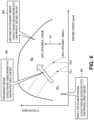
- FIG. 6 is a diagram illustrating, as an example, an operation region of the engine 1 and a basic concept of a control method of the engine 1.
- the operation region of the engine 1 is divided into plural regions in accordance with a level of the load (torque) and a level of the engine speed.
- the operation region of the engine 1 includes a first region R1 on a lower rotation side of a first rotational speed Th and a second region R2 on a higher rotation side of this first rotational speed Th1.
- the first rotational speed Th1 is set low compared to a case where the load is low.
- the first region R1 is an operation region in a range of low load and low rotation
- the second region R2 is an operation region in a range of high load and high rotation.
- a boundary between the first region R1 and the second region R2 shifts toward a lower rotation side as the load becomes higher and shifts toward a lower load side as the engine speed becomes higher.
- the ECU 100 can execute both of the first stationary mode and the second stationary mode, which will be described later, in an operation region on the lower load side between two operation regions which result from division in accordance with the level of load. In the operation region on the higher load side between the two operation regions resulting from the division, the ECU 100 can execute only the second stationary mode in accordance with the magnitude of load.
- the ECU 100 operates the engine 1 in the first stationary mode which corresponds to a blowdown supercharging system in the first region R1, operates the engine 1 in the second stationary mode which is similar to a usual supercharging system in the second region R2, and operates the engine 1 in the transient mode which is different from both of the blowdown supercharging system and the usual supercharging system in a transient period in which transition is made from the first region R1 to the second region R2.
- the ECU 100 operates the engine 1 in the first stationary mode which corresponds to the blowdown supercharging system.
- the ECU 100 controls the first switching valve 21 and the second switching valve 22 and thereby sets the exhaust passage 16 to the blowdown state where the first switching valve 21 is closed and the second switching valve 22 is opened (see a reference character M1 in FIG. 6 ).
- the blowdown state the exhaust gas exhausted from the first exhaust valves 7 to the first exhaust passage 161 passes through the turbine 17 and is led to the catalyst 20, and the exhaust gas exhausted from the second exhaust valves 8 to the second exhaust passage 162 is exhausted to the catalyst 20 while circumventing the turbine 17.
- the ECU 100 may set the opening of the first switching valve 21 to a fully closed state and set the opening of the second switching valve 22 to a fully open state.
- the ECU 100 may control the electromagnetic actuators 93 and thereby open the first exhaust valve 7 and the second exhaust valve 8 by the first cam set 9A. Accordingly, the first exhaust valve 7 opens at the time point EO1 earlier than at least the initial period of the exhaust stroke, and the second exhaust valve 8 opens at the time point EO2 later than the first exhaust valve 7.
- blowdown supercharging is realized. That is, when the first exhaust valve 7 is opened at a timing earlier than the initial period of the exhaust stroke, in response to this opening, high-pressure exhaust gas is jetted into the first exhaust passage 161, and the high-pressure exhaust gas rotates the turbine 17. Meanwhile, the second exhaust valve 8 is opened at a timing later than the first exhaust valve 7, and the exhaust gas which has not completely been exhausted through the first exhaust valve 7 is thereby exhausted to the outside of a vehicle while circumventing or bypassing the turbine 17.
- the first exhaust passage 161 is connected with the catalyst 20 via the turbine 17, but the second exhaust passage 162 is connected with the catalyst 20 not via the turbine 17. Because the connection is made not via the turbine 17, the second exhaust passage 162 is at a lower pressure than the first exhaust passage 161. Accordingly, pump loss (discharge loss) of the second exhaust valve 8 is reduced. In addition to that, because the valve-opening time point EO2 of the second exhaust valve 8 is made later, the exhaust gas in the cylinder 2 is exhausted with low pump loss.
- pump loss (intake loss) of the intake valve 4 lowers in accordance with an increase in the supercharging pressure. It has been considered that by a combination of this fact and the above-described reduction in discharge loss of the second exhaust valve 8, the pump loss for the whole engine 1 tends to be lowered as the supercharging pressure is increased.
- FIG. 9 is a plot graph illustrating, as an example, the relationship between a compressor outlet pressure and the pump loss.
- the horizontal axis in FIG. 9 represents an outlet pressure of the compressor 13, in other words, the supercharging pressure
- the vertical axis in FIG. 9 represents a PMEP (pumping mean effective pressure) that indicates the magnitude of the pump loss which is obtained by summing the discharge loss due to the exhaust valves and the intake loss due to the intake valves.
- the plot graph illustrated in FIG. 9 means that as the value of the vertical axis becomes greater, the pump loss is lower and fuel efficiency performance is more excellent.
- a rhombic plot G1 in FIG. 9 corresponds to a low rotation range around 1,000 rpm
- a circular plot G2 corresponds to an intermediate rotation range around 2,000 rpm
- a rectangular plot G3 corresponds to a high rotation range around 3,000 rpm.
- the pump loss changes in a direction to improve the fuel efficiency performance in accordance with an increase in the supercharging pressure.
- the intermediate rotation range represented by the plot G2 although not as much as the pump loss in the low rotation range, the pump loss shifts while slightly lowering or maintaining a generally constant value in accordance with an increase in the supercharging pressure.
- the plots G2 also represent that the pump loss degrades at each supercharging pressure compared to the plots G1.
- the inventors of the present application intensively analyzed factors of the newly found tendency. As a result, it has become clear that an increase in an exhaust resistance due to the second exhaust valve 8 is a main factor. That is, because a combustion frequency per predetermined time is higher in a higher rotation range, a total amount of exhaust gas becomes more. Because the area of the second exhaust valve 8 is limited, more pumping work is needed for exhausting a large amount of exhaust gas.
- the inventors of the present application have newly conceived to operate the engine 1 in the second stationary mode which is different from the above first stationary mode in the second region R2 on a higher rotation side of the first region R1.
- the ECU 100 operates the engine 1 in the second stationary mode which is different from the blowdown supercharging system. Switching from the first stationary mode to the second stationary mode is executable by controlling the first switching valve 21 and the second switching valve 22 by the ECU 100, for example.
- the ECU 100 controls the first switching valve 21 and the second switching valve 22 and thereby sets the exhaust passage 16 to the non-blowdown state where the first switching valve 21 is opened and the second switching valve 22 is closed (see a reference character M2 in FIG. 6 ).
- the first exhaust passage 161 is connected with the turbine 17, and further the second exhaust passage 162 is also connected with the turbine 17 via the third exhaust passage 163 and the first exhaust passage 161.
- the exhaust gas exhausted by opening of the second exhaust valve 8 is guided to the turbine 17 via the first exhaust passage 161 similarly to the exhaust gas related to the first exhaust valve 7. Accordingly, because the supercharging pressure can further be made higher, lower pump loss of the intake valve 4 can be realized. As a result, even in a high rotation range, it becomes possible to reduce an increase in the pump loss for the whole engine.
- a triangular plot G4 in FIG. 9 represents the pump loss in a case where one of switching of the first and second switching valves 21 and 22 and cam switching described later is performed in a high rotation range around 3,000 rpm. As illustrated in FIG. 9 , the plots G4 also represent that an improvement related to the pump loss is made at each supercharging pressure compared to the plots G3. Further, in accordance with an increase in the supercharging pressure, the pump loss represented by the plots G4 is changed more gently than the pump loss represented by the plots G3.
- the first rotational speed Th1 may be set lower as the load becomes higher.
- closing the second switching valve 22" in the second stationary mode is not limited to setting the second switching valve 22 to the fully closed state.
- the opening of the second switching valve 22 may be set to at least a closing side compared to the fully open state or a closing side compared to the first switching valve 21.
- the ECU 100 sets the opening of the second switching valve 22 to a closing side compared to the fully open state in a case where the engine speed is higher than the first rotational speed Th1.
- the opening of the second switching valve 22 may smaller than the fully open state in a case where the engine speed is higher than the first rotational speed Th1.
- the ECU 100 sets the opening of the first switching valve 21 to the fully open state and sets the opening of the second switching valve 22 to the fully closed state or to a closing side compared to the fully open state.
- the ECU 100 adjusts the opening of the second switching valve 22 such that the channel area of the second exhaust passage 162 becomes large compared to a case where the load is low.
- the opening of the second switching valve 22 becomes larger as the load becomes higher.
- the ECU 100 may set the opening of the second switching valve 22 large compared to a case where the load is low.
- the ECU 100 divides the second region R2 into two parts of a high-rotation high-load region and a low-rotation low-load region and conducts opening adjustment of the second switching valve 22 in the former region.
- the rotational speed for dividing the second region R2 into two parts can be set higher when the load on the engine 1 is high than when the load is low.
- the second rotational speed Th2 is set in such a manner and thereby changes generally in parallel with the first rotational speed Th1.
- the ECU 100 controls the second switching valve 22 so as to make the opening (W/G opening) larger when the load on the engine 1 is high than when the load is low.
- the opening (W/G opening) of the second switching valve 22 is set to become larger as the load on the engine 1 becomes higher.
- the ECU 100 guides a part of the exhaust gas exhausted by opening of the second exhaust valve 8 to the turbine 17 but causes the remaining exhaust gas to circumvent the turbine 17.
- the exhaust gas amount guided to the turbine 17 is controlled through the opening adjustment of the second switching valve 22. Consequently, the second switching valve 22 can be utilized as a so-called wastegate valve, and further the supercharging pressure can be stabilized.
- the ECU 100 in a case where the engine speed is the first rotational speed Th1 or more or higher than the first rotational speed Th1, that is, in a case where the engine 1 is operated in the second stationary mode, the ECU 100 according to this embodiment is configured to open and/or close the first and second exhaust valves 7 and 8 by the second cam set 9B in addition to the above-described switching from the blowdown state to the non-blowdown state. Switching to the second cam set 9B is executable by controlling at least the electromagnetic actuators 93 by the ECU 100.
- the ECU 100 opens and/or closes the first and second exhaust valves 7 and 8 by the first cam set 9A in the first region R1 on the low rotation side but opens and/or closes the first and second exhaust valves by the second cam set 9B in the second region R2 on the high rotation side (see a reference character M2 in FIG. 6 ).
- the third cam profiles 913 constituting the second cam set 9B may have larger valve-opening angles than the first and second cam profiles 911 and 912 constituting the first cam set 9A.
- a cross-shaped plot G5 in FIG. 9 represents the pump loss in a case where both of switching of the first and second switching valves 21 and 22 and switching from the first cam set 9A to the second cam set 9B are performed in a high rotation range around 3,000 rpm.
- the plots G4 represent that an improvement related to the pump loss is made at each supercharging pressure compared to the plots G3 and the plots G4. Further, in accordance with an increase in the supercharging pressure, the pump loss represented by the plots G5 is gently changed differently from the pump loss represented by the plots G3 and the plots G4.
- the first cam profile 911 sets the valve-opening time point EO1 of the first exhaust valve 7 to the intermediate period of the combustion stroke. Accordingly, for example, compared to a case where the valve opening time point EO1 is set to the end period of the combustion stroke, the valve-opening angle can be set large, and valve acceleration can be reduced. Accordingly, while the lift amount is made as large as possible, an occurrence of valve jump can be inhibited. Further, when the valve-opening time point EO1 is set to the intermediate period of the combustion stroke, this is also advantageous in reduction in influence on combustion torque compared to a case where the valve-opening time point EO1 is set to the initial period of the combustion stroke, for example.
- the second cam profile 912 sets the valve-opening time point EO2 of the second exhaust valve 8 to the end period of the combustion stroke. Accordingly, for example, compared to a case where the valve opening time point EO2 is set to the initial period of the exhaust stroke, the valve-opening angle can be set large, and the valve acceleration can be reduced. Consequently, while the lift amount is made as large as possible, an occurrence of the valve jump can be inhibited.
- the second exhaust valve 8 acts at a high speed on the high rotation side, there has been concern about an occurrence of the valve jump of the second exhaust valve 8 in a configuration in related art.
- the second cam profile 912 is not used in the second region R2 on the high rotation side, the lift amount can be made larger than related art.
- the second cam profile 912 sets the lift amount of the second exhaust valve 8 relatively larger than the lift amount of the first exhaust valve 7 by the first cam profile 911. Accordingly, the exhaust gas amount which circumvents the turbine 17 can sufficiently be secured, and this further becomes advantageous in reduction in the discharge loss of the second exhaust valve 8.
- the lift amount of the second exhaust valve 8 by the second cam profile 912 is set relatively smaller than the lift amount of the second exhaust valve 8 by the third cam profile 913, and an occurrence of the valve jump can thereby more certainly be inhibited.
- the ECU 100 operates the engine 1 in the transient mode in transition from the first region R1 to the second region R2.
- the ECU 100 can cause a timing when the first switching valve 21 is opened and the second switching valve 22 is closed, in other words, a timing when switching is made from the blowdown state to the non-blowdown state and a timing when switching is made from the first cam set 9A to the second cam set 9B to be different from each other.
- Both of opening the first switching valve 21 and closing the second switching valve 22 and switching from the first cam set 9A to the second cam set 9B cause an increase in the supercharging pressure.
- a rapid increase in the supercharging pressure is caused.
- a rapid increase in the supercharging pressure may cause a torque shock and further degradation of drivability and may thus result in inconvenience.
- the ECU 100 temporarily goes through the transient mode in transition from the first stationary mode to the second stationary mode.
- the ECU 100 leaves the transient mode and transits to the second stationary mode. After transiting to the second stationary mode, the ECU 100 executes switching from the first cam set 9A to the second cam set 9B. In such a configuration, the supercharging pressure can be caused to smoothly rise. Accordingly, a rapid change in the supercharging pressure can be inhibited, and further drivability can be kept proper.
- the ECU 100 determines whether or not the supercharging pressure reaches the target supercharging pressure based on a detection signal by the supercharging pressure sensor SW1. Then, in transition from the first region R1 to the second region R2, the ECU 100 temporarily operates the engine 1 in the transient mode until it is determined that the supercharging pressure reaches the target supercharging pressure. During the transient mode, the ECU 100 adjourns switching from the first cam set 9A to the second cam set, and the ECU 100 executes switching from the blowdown state to the non-blowdown state regardless of whether the supercharging pressure reaches the target supercharging pressure.
- switching from the first cam set 9A to the second cam set 9B can be performed after the supercharging pressure rises to a certain extent, and the supercharging pressure can be caused to smoothly rise. Accordingly, a rapid change in the supercharging pressure can be inhibited, and further drivability can be kept proper.
- the ECU 100 sets the opening of the first switching valve 21 to the fully open state and sets the opening of the second switching valve 22 to the fully closed state or to a closing side compared to the fully open state.
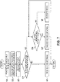
- FIG. 7 is a flowchart illustrating, as an example, the control process of the engine 1
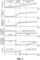
- FIG. 8 is a diagram illustrating, as an example, the time chart corresponding to FIG. 7 .
- the ECU 100 may read detection signals by the supercharging pressure sensor SW1, the rotational speed sensor SW2, the accelerator opening sensor SW3, and so forth.
- next step S2 the ECU 100 may make a determination about the operation state of the engine 1 based on the detection signals read in step S1. Specifically, in this step S2, the ECU 100 may calculate the load on the engine 1 and calculate the target supercharging pressure and so forth of the engine 1 based on the calculated load and the engine speed. In transition from the first region R1 to the second region R2, the target supercharging pressure is set higher.
- the ECU 100 may calculate the first rotational speed Th1 as the boundary between the first region R1 and the second region R2 based on the load calculated in step S2. As described above, the first rotational speed Th1 becomes lower as the load on the engine 1 becomes larger.
- next step S4 the ECU 100 may determine whether or not the present engine speed is less than the first rotational speed Th1 based on the engine speed detected in step S1 and the first rotational speed Th1 calculated in step S3. This determination is equivalent to a determination about whether or not the present operation state is in the first region R1.
- the ECU 100 may move the control process to step S5 in a case where this determination is YES but moves the control process to step S6 in a case of NO.
- step S5 the ECU 100 may operate the engine 1 in the first stationary mode.
- the control process moves from step S4 to step S5.
- the ECU 100 closes the first switching valve 21 and sets that to the fully closed state but opens the second switching valve 22 and sets that to the fully open state.
- the ECU 100 opens the first exhaust valve 7 and the second exhaust valve 8 by the first cam set 9A. As long as the operation state is in the first region R1, the ECU 100 operates the engine 1 in the first stationary mode.
- the engine speed reaches the first rotational speed Th1 at a time T1 in FIG. 8 .
- the ECU 100 determines that the present operation state is on the outside of the first region R1 and moves the control process to step S6.
- step S6 the ECU 100 may determine whether or not the detected supercharging pressure reaches a target supercharging pressure Pc based on the detection signal by the supercharging pressure sensor SW1 which is read in step S1.
- the ECU 100 moves the control process to step S7 in a case where this determination is YES but moves the control process to step S8 in a case where the control process is NO.
- step S8 the ECU 100 operates the engine 1 in the transient mode.
- step S7 the ECU 100 operates the engine 1 in the second stationary mode.
- the control process moves from step S6 to step S8.
- the ECU 100 opens the first switching valve 21 and sets that to the fully open state but closes the second switching valve 22 and sets that to the fully closed state (in other words, the exhaust passage 16 is set to the blowdown state).
- the ECU 100 suspends switching from the first cam set 9A to the second cam set 9B and continues to open the first and second exhaust valves 7 and 8 by the first cam set 9A.
- the ECU 100 operates the engine 1 in the transient mode.
- the ECU 100 moves the control process to step S7.
- the ECU 100 executes switching from the first cam set 9A to the second cam set 9B while setting the exhaust passage 16 to the blowdown state and starts opening the first and second exhaust valves 7 and 8 by the second cam set 9B.
- the engine speed becomes the second rotational speed Th2 or more at and after a time T3 in FIG. 8 .
- This second rotational speed Th2 may be calculated based on the load on the engine 1 in above step S3, for example.
- the ECU 100 may gradually open the second switching valve 22 from the fully closed state and utilizes that as a wastegate valve. Accordingly, the supercharging pressure can be stabilized. In this case, the opening of the second switching valve 22 is set to become larger when the load on the engine 1 is high than when the load is low.
- the transient mode is executed in accordance with the determination about the supercharging pressure; however, in a case where the operation state of the engine 1 is in the first region R1 (in other words, a case where the engine speed is lower than the first rotational speed), the first stationary mode may be immediately executed not via the steps related to the transient mode.
- the ECU 100 in transition from the high rotation side to the low rotation side, in other words, in at and after from the second region R2 to the first region R1, is configured to close the first switching valve 21 and open the second switching valve 22 (a process to switch the exhaust passage 16 from the non-blowdown state to the blowdown state) and to perform switching from the second cam set 9B to the first cam set 9A at generally the same timing.
- this process is executable by controlling the first switching valve 21, the second switching valve 22, and the electromagnetic actuators 93 by the ECU 100.
- a configuration is made such that in the second stationary mode after transition from the first region R1 to the second region R2, both of switching of the exhaust passage 16 to the non-blowdown state and switching from the first cam set 9A to the second cam set 9B are performed; however, the present disclosure is not limited to such a configuration.
- a configuration may be made such that only switching of the exhaust passage 16 is performed.
- a configuration is made such that based on the fact that the supercharging pressure reaches the target supercharging pressure, transition is made from the transient mode to the second stationary mode; however, the present disclosure is not limited to such a configuration.
- a configuration may be made such that transition is made from the transient mode to the second stationary mode in a case where the engine speed becomes the second rotational speed Th2 or more, and a configuration may be made such that transition is made based on an engine load.
- an engine to which the technique disclosed herein is applicable is not limited to the engine in the above-described configuration.
- the technique disclosed herein is applicable to engines in various configurations.
- the present disclosure can be applied to a rotary engine with a turbosupercharger, for example. Further, the present disclosure can be applied to a gasoline engine which uses gasoline as a fuel.
Landscapes
- Engineering & Computer Science (AREA)
- Mechanical Engineering (AREA)
- General Engineering & Computer Science (AREA)
- Chemical & Material Sciences (AREA)
- Combustion & Propulsion (AREA)
- Output Control And Ontrol Of Special Type Engine (AREA)
- Supercharger (AREA)
Abstract
Description
- The technique disclosed herein relates to a control device for an engine.
- In recent years, although electric vehicles, such as electric automobiles, have been widely used, many vehicles still use an engine as a power source. Further, demands on engines, such as further improvements in thermal efficiency, are still high.
- For example,
Patent Literature 1 discloses, as one example of an engine using a blowdown supercharging system, an engine that, in each combustion chamber, includes plural exhaust ports which communicate with exhaust passages independent from each other and plural exhaust valves which are disposed to the respective exhaust ports and whose valve-opening time points are different from each other. - Here, the gas passage is composed of a first exhaust passage which communicates with a first exhaust valve opening in an early period and in which a turbine of a turbosupercharger is disposed and a second exhaust passage which communicates with a second exhaust valve opening at a time point later than the first exhaust valve and is united with the first exhaust passage while circumventing the turbine.
- In the engine, high-pressure exhaust gas jetted out in response to opening of the first exhaust valve rotates the turbine from an end period of an expansion stroke to an intermediate period of an exhaust stroke. Meanwhile, from the intermediate period to an end period of the exhaust stroke, the exhaust gas which has not completely been exhausted through the first exhaust valve is exhausted in response to opening of the second exhaust valve while circumventing or bypassing the turbine.
- In a case where the engine according to
Patent Literature 1 is employed, the second exhaust passage is not connected with the turbine. Thus, the second exhaust passage is at a lower pressure than the first exhaust passage. Accordingly, pump loss (hereinafter, also referred to as "discharge loss") of the second exhaust valve is reduced. In addition to that, because a valve-opening time point of the second exhaust valve is made later, exhaust gas in a cylinder is exhausted with low pump loss. - Here, in a case where exhaust gas is exhausted via the second exhaust passage, an exhaust gas amount which passes through the turbine is decreased. In this case, there is concern about lowering of a supercharging pressure. However, the first exhaust valve is opened early, the high-pressure exhaust gas is thereby jetted out, and the supercharging pressure can be secured.
- [Patent Literature 1]
Japanese Patent Laid-Open No. 11-210449 - It has been considered that in a case where the above blowdown supercharging system disclosed in
Patent Literature 1 is employed, by a combination of lowering of pump loss (hereinafter, also referred to as "intake loss") of an intake valve in response to an increase in a supercharging pressure and the above-described reduction in discharge loss, pump loss for a whole engine tends to be improved as the supercharging pressure is increased. - However, when the inventors of the present application inspected findings in related art, the above-described tendency was observed when an engine speed was low; however, it has newly been found that when the engine speed is high, pump loss tends to increase for the whole engine as the supercharging pressure is increased.
- The inventors of the present application intensively analyzed factors of the newly found tendency. As a result, it has become clear that an increase in an exhaust resistance due to a second exhaust valve is a main factor. That is, because a combustion frequency per predetermined time is higher in a higher rotation range, a total amount of exhaust gas becomes more. Because the area of the second exhaust valve is limited, more pumping work is needed for exhausting a large amount of exhaust gas.
- As a measure for reducing the pumping work by the second exhaust valve, for example, increasing an exhaust amount by a first exhaust valve may be raised. However, because a first exhaust passage which is opened and closed by the first exhaust valve is at a relatively high pressure, a large amount of pumping work is assigned to the first exhaust valve, and this may result in inconvenience.
- The technique disclosed herein has been made in consideration of such points, and an object thereof is to reduce an increase in pump loss in a high rotation range.
- The above object is achieved by the invention as defined in
claim 1. - A first aspect of the present disclosure relates to a control device for an engine, the control device including: a first exhaust port and a second exhaust port which open in each cylinder of the engine; a first exhaust valve which opens and closes the first exhaust port; a second exhaust valve which opens and closes the second exhaust port; an exhaust valve mechanism which is configured to open the first exhaust valve at least at an earlier time point than an initial period of an exhaust stroke and to meanwhile open the second exhaust valve at a later time point than the first exhaust valve; an exhaust passage which is connected with the first exhaust port and the second exhaust port; and a supercharger (or a turbocharger) which is composed of a turbine provided to the exhaust passage and a compressor provided to an intake passage of the engine.
- Particularly, the exhaust valve mechanism is configured to open the first exhaust valve earlier than the exhaust stroke and to open the second exhaust valve later than the first exhaust valve.
- In the first aspect, the exhaust passage has a first exhaust passage which is connected with the first exhaust port and in which the turbine is arranged, a second exhaust passage which is connected with the second exhaust port and merges with the first exhaust passage while circumventing the turbine, and a third exhaust passage which connects the first exhaust passage on an upstream side of the turbine with the second exhaust passage.
- Furthermore, the control device for an engine further includes: a first switching valve which is arranged in the third exhaust passage and changes a channel area (or an open area) of the third exhaust passage; a second switching valve which is arranged in the second exhaust passage on a downstream side of a connection portion with the third exhaust passage and on an upstream side of a merging portion with the first exhaust passage and which changes a channel area of the second exhaust passage; a rotational speed sensor which detects an engine speed; and a controller which controls opening and closing of the first switching valve and the second switching valve based on a detection signal by the rotational speed sensor, and the controller controls the first switching valve and the second switching valve to close the first switching valve and open the second switching valve in a case where the engine speed is lower than a predetermined first rotational speed and to open the first switching valve and close the second switching valve in a case where the engine speed is higher than the first rotational speed.
- Here, a term of "closing a valve" includes a relatively closing state to a fully open state. What is meant by this term is not limited to a fully closed state. For example, in a case where the engine speed is lower than the first rotational speed, an opening of the second switching valve may be set to the fully closed state or a closing side compared to the fully open state. The same applies to a term of "opening a valve".
- In the first aspect, the controller closes the first switching valve and opens the second switching valve in a low rotation range, thereby causes the first exhaust passage to be connected with the turbine, and causes the second exhaust passage not to be connected with the turbine. In this case, high-energy exhaust gas exhausted by early opening of the first exhaust valve passes through the turbine via the first exhaust passage. By using high-energy exhaust gas, a necessary supercharging pressure is secured. Meanwhile, the exhaust gas exhausted by opening of the second exhaust valve which is conducted later than the first exhaust valve circumvents the turbine via the second exhaust passage. Because the second exhaust passage is at a relatively low pressure, lower pump loss of the second exhaust valve can be realized.
- Meanwhile, in a high rotation range where there is concern about degradation of pump loss, the controller opens the first switching valve and closes the second switching valve. The first exhaust passage is connected with the turbine, and further the second exhaust passage is also connected with the turbine via the third exhaust passage and the first exhaust passage. In this case, the exhaust gas exhausted by opening of the second exhaust valve is guided to the turbine via the first exhaust passage similarly to the exhaust gas related to the first exhaust valve. Accordingly, because the supercharging pressure can further be made higher, lower pump loss of an intake valve (lowering of intake loss) can be realized. As a result, even in a high rotation range, it becomes possible to reduce an increase in the pump loss for the whole engine.
- Further, in a second aspect of the present disclosure, in a case where a load on the engine is high, the first rotational speed may be set low compared to a case where the load is low.
- In the second aspect, the first rotational speed is set or becomes lower as the load becomes higher. In other words, as the engine speed becomes lower, the relationship of "engine speed < first rotational speed" is satisfied even with a higher load, and a blowdown supercharging system is conducted. In the blowdown supercharging system, because there is concern about an increase in the pump loss on a high rotation side, such a setting is advantageous in maximizing fuel efficiency.
- Further, in a third aspect of the present disclosure, the controller may set an opening of the second switching valve to a closing side compared to a fully open state in a case where the engine speed is higher than the first rotational speed and may adjust the opening of the second switching valve such that the channel area of the second exhaust passage becomes large in a case where the load on the engine is high compared to a case where the load is low. Particularly, the controller may set an opening of the second switching valve to be smaller than a fully open state in a case where the engine speed is higher than the first rotational speed and may control the second switching valve to open more as the load on the engine becomes higher.
- In the third aspect, the controller guides a part of the exhaust gas exhausted by opening of the second exhaust valve to the turbine but causes the remaining exhaust gas to circumvent the turbine. An exhaust gas amount guided to the turbine is controlled through the opening adjustment of the second switching valve. Consequently, the second switching valve can be utilized as a so-called wastegate valve, and further the supercharging pressure can be stabilized.
- Further, in a fourth aspect of the present disclosure, the control device for an engine may further include an exhaust valve mechanism which drives the first exhaust valve and the second exhaust valve, the exhaust valve mechanism may have a first cam set composed of a first cam profile which opens the first exhaust valve at least at an earlier time point than the initial period of the exhaust stroke and a second cam profile which opens the second exhaust valve at a later time point than the first exhaust valve, a second cam set composed of a pair of third cam profiles whose valve-opening angles are set larger than the first cam profile and the second cam profile and which open the first exhaust valve and the second exhaust valve, and a cam switching unit which performs switching to the first cam set or the second cam set, the controller may be configured to control switching by the cam switching unit based on the detection signal by the rotational speed sensor, and the controller may control the cam switching unit to open and close the first exhaust valve and the second exhaust valve by the first cam set in a case where the engine speed is lower than the first rotational speed and to open and close the first exhaust valve and the second exhaust valve by the second cam set in a case where the engine speed is higher than the first rotational speed.
- Particularly, the cam switching unit may switch the first cam set and the second cam set. In other words, the cam switching unit may perform switching to the first cam set from the second cam set, and/or switching to the second cam set from the first cam set.
- In the fourth aspect, the controller opens and closes the first and second exhaust valves by the first cam set on a low rotation side but opens and closes the first and second exhaust valves by the second cam set on a high rotation side. The third cam profiles constituting the second cam set have larger valve-opening angles than the first and second cam profiles constituting the first cam set. Thus, exhaust efficiency is improved, and discharge loss of the first and second exhaust valves in a high rotation range can be reduced. Accordingly, by a combination with the above-described lower pump loss of the intake valve, it becomes possible to reduce an increase in the pump loss for the whole engine.
- Further, in a fifth aspect of the present disclosure, the first cam profile may set a valve-opening time point of the first exhaust valve to an intermediate period of a combustion stroke of the engine and may set a valve-closing time point of the first exhaust valve to fall within a period from the initial period to an intermediate period of the exhaust stroke of the engine.
- Here, "an intermediate period of a combustion stroke" indicates an intermediate period in a case where the combustion stroke is divided into three generally equal parts of an initial period, an intermediate period, and an end period. Similarly, "an initial period of an exhaust stroke" indicates an initial period in a case where the exhaust stroke is divided into three generally equal parts of an initial period, an intermediate period, and an end period.
- In the fifth aspect, the valve-opening time point of the first exhaust valve is set to the intermediate period of the combustion stroke. Accordingly, for example, compared to a case where the valve opening time point is set to the end period of the combustion stroke, the valve-opening angle can be set large, and valve acceleration can be reduced. Accordingly, while the lift amount is made as large as possible, an occurrence of valve jump can be inhibited. Further, when the valve-opening time point is set to the intermediate period of the combustion stroke, this is also advantageous in reduction in influence on combustion torque compared to a case where the valve-opening time point is set to the initial period of the combustion stroke, for example.
- Further, in a sixth aspect of the present disclosure, the second cam profile may set a valve-opening time point of the second exhaust valve to the end period of the combustion stroke of the engine and may set a valve-closing time point of the second exhaust valve to fall within a period from an end period of the exhaust stroke to an initial period of an intake stroke of the engine.
- Here, "an end period of a combustion stroke" indicates an end period in a case where the combustion stroke is divided into three generally equal parts of an initial period, an intermediate period, and an end period. Similarly, "an end period of an exhaust stroke" indicates an end period in a case where the exhaust stroke is divided into three generally equal parts of an initial period, an intermediate period, and an end period. "An initial period of an intake stroke" indicates an initial period in a case where the intake stroke is divided into three generally equal parts of an initial period, an intermediate period, and an end period.
- In the sixth aspect, the valve-opening time point of the second exhaust valve is set to the end period of the combustion stroke. Accordingly, for example, compared to a case where the valve opening time point is set to the initial period of the exhaust stroke, the valve-opening angle can be set large, and the valve acceleration can be reduced. Consequently, while the lift amount is made as large as possible, an occurrence of the valve jump can be inhibited.
- Further, in a seventh aspect of the present disclosure, the first cam profile may set a lift amount of the first exhaust valve smaller than a lift amount of the first exhaust valve by the third cam profile and a lift amount of the second exhaust valve by the second cam profile, and the second cam profile may set a lift amount of the second exhaust valve smaller than a lift amount of the second exhaust valve by the third cam profile.
- In general, because the second exhaust valve acts at a high speed on a high rotation side, there has been concern about an occurrence of the valve jump of the second exhaust valve in a configuration in related art. However, in a case of the present disclosure, because the second cam profile is not used on a high rotation side, the lift amount can be made larger than related art.
- Accordingly, the second cam profile according to the seventh aspect sets the lift amount of the second exhaust valve relatively larger than the lift amount of the first exhaust valve by the first cam profile. Accordingly, the exhaust gas amount which circumvents the turbine can sufficiently be secured, and this further becomes advantageous in reduction in the discharge loss of the second exhaust valve. Here, the lift amount of the second exhaust valve by the second cam profile is set relatively smaller than the lift amount of the second exhaust valve by the third cam profile, and an occurrence of the valve jump can thereby more certainly be inhibited.
- Further, in an eighth aspect of the present disclosure, an operation region of the engine may include a first region on a lower rotation side of the first rotational speed and a second region on a higher rotation side of the first rotational speed, and the controller may be configured to cause a timing when the first switching valve is opened and the second switching valve is closed and a timing when switching is made from the first cam set to the second cam set to be different from each other in transition from the first region to the second region.
- Both of opening the first switching valve and opening the second switching valve and switching from the first cam set to the second cam set cause an increase in the supercharging pressure. Thus, when those pieces of control are simultaneously performed in transition from a state where the supercharging pressure is low to a state where the supercharging pressure is high, a rapid increase in the supercharging pressure is caused. A rapid increase in the supercharging pressure causes a torque shock and further degradation of drivability and may thus result in inconvenience.
- Accordingly, the controller according to the eighth aspect causes the timing when open-closed states of the first and second switching valves are switched and the timing when switching is made from the first cam set to the second cam set to be different from each other. Accordingly, the supercharging pressure can be caused to smoothly rise. Accordingly, a rapid change in the supercharging pressure can be inhibited, and further drivability can be kept proper.
- Further, in a ninth aspect of the present disclosure, the control device for an engine may further include a supercharging pressure sensor which detects a supercharging pressure of the supercharger, the controller may set a target supercharging pressure in accordance with an operation state of the engine, the controller may determine whether or not the supercharging pressure reaches the target supercharging pressure based on a detection signal by the supercharging pressure sensor, and in transition from the first region to the second region, the controller may adjourn switching from the first cam set to the second cam set until a determination is made that the supercharging pressure reaches the target supercharging pressure and may open the first switching valve and close the second switching valve regardless of whether or not the supercharging pressure reaches the target supercharging pressure.
- In the ninth aspect, the controller executes switching from the first cam set to the second cam set based on whether the supercharging pressure reaches the target supercharging pressure. Accordingly, for example, switching from the first cam set to the second cam set can be performed after the supercharging pressure rises to a certain extent, and the supercharging pressure can be caused to smoothly rise. Accordingly, a rapid change in the supercharging pressure can be inhibited, and further drivability can be kept proper.
- As described above, in the present disclosure, an increase in pump loss in a high rotation range can be reduced.
-
-
FIG. 1 is a diagram illustrating, as an example, a configuration of an engine. -
FIG. 2 is a block diagram illustrating, as an example, a configuration of a control device for an engine. -
FIG. 3 is a diagram illustrating, as an example, a configuration of a valve mechanism of exhaust valves. -
FIG. 4 is a diagram for explaining switching between exhaust passages. -
FIG. 5 is a diagram illustrating, as an example, lift curves corresponding to cam sets. -
FIG. 6 is a diagram illustrating, as an example, an operation region of the engine and a basic concept of a control method of the engine. -
FIG. 7 is a flowchart illustrating, as an example, a control process of the engine. -
FIG. 8 is a diagram illustrating, as an example, a time chart corresponding toFIG. 7 . -
FIG. 9 is a plot graph illustrating, as an example, the relationship between a compressor outlet pressure and pump loss. - Embodiments of the present disclosure will hereinafter be described based on drawings. All of the features as shown in the drawings may not necessarily be essential. Note that the following descriptions are examples.
FIG. 1 is a diagram illustrating, as an example, a configuration of an engine.FIG. 2 is a block diagram illustrating, as an example, a configuration of a control device for an engine.FIG. 3 is a diagram illustrating, as an example, a configuration of a valve mechanism of exhaust valves.FIG. 4 is a diagram for explaining switching between exhaust passages. - An
engine 1 hascylinders 2. In thecylinder 2, an intake stroke, a compression stroke, a combustion stroke, and an exhaust stroke are repeated. Theengine 1 is a four-stroke engine. Further, theengine 1 is installed in a vehicle or an automobile particularly with four wheels. The automobile travels by operation of theengine 1. A fuel for theengine 1 may be diesel fuel in this configuration example. - The
engine 1 has acylinder block 1a. In an internal portion of thecylinder block 1a, one orplural cylinders 2 are formed.FIG. 1 illustrates fourcylinders 2 which are aligned in series. Theengine 1 illustrated inFIG. 1 may be an in-line four-cylinder diesel engine and is at the same time an engine with a turbosupercharger, which includes a supercharger or aturbocharger 19 described later. - Each of the
cylinder 2 houses a piston which is not illustrated. This piston forms a combustion chamber together with thecylinder 2. Note that "combustion chamber" is not limited to the meaning of a space which is formed at a timing when the piston reaches a compression top dead center. "Combustion chamber" may mean a space which is formed with thecylinder 2 and so forth regardless of the position of the piston. - This
engine 1 includes, in each of thecylinders 2, one or more, particularly twointake ports intake valves intake ports cylinders 2 and are provided on one side (upper side inFIG. 1 ) in an intake-exhaust direction which is orthogonal to an alignment direction of the cylinders 2 (cylinder array direction). The twointake valves intake ports - The
engine 1 includes, in each of thecylinders 2, first andsecond exhaust ports second exhaust valves exhaust valve mechanism 9 is illustrated only inFIG. 2 ). The first andsecond exhaust ports cylinders 2 and are provided on the other side (lower side inFIG. 1 ) in the intake-exhaust direction. Here, "the other side in the intake-exhaust direction" indicates the opposite direction to "one side in the intake-exhaust direction". Thefirst exhaust valve 7 opens and/or closes thefirst exhaust port 5. Thesecond exhaust valve 8 opens and/or closes thesecond exhaust port 6. Theexhaust valve mechanism 9 drives thefirst exhaust valve 7 and thesecond exhaust valve 8 so as to realize predetermined valve timings and valve lifts. As described later, theexhaust valve mechanism 9 opens thefirst exhaust valve 7 at an earlier time point than an initial period of the exhaust stroke (e.g. the bottom dead center) and can meanwhile open thesecond exhaust valve 8 at a later time point than thefirst exhaust valve 7. - Here, as illustrated in
FIG. 2 andFIG. 3 , theexhaust valve mechanism 9 is composed of a cam-switching type variable valve mechanism. Although details will be described later, theexhaust valve mechanism 9 is configured to be capable of switching a first mode in which thefirst exhaust valve 7 and thesecond exhaust valve 8 are opened by a first cam set 9A and a second mode in which thefirst exhaust valve 7 and thesecond exhaust valve 8 are opened by a second cam set 9B. - The
engine 1 includes afuel injection valve 10 in each of the cylinders 2 (illustrated only inFIG. 2 ). Thefuel injection valve 10 is mounted on a general upper surface of the combustion chamber upper surface and directly injects fuel into the combustion chamber. - The
engine 1 includes anintake passage 11 through which intake air to be supplied to each of thecylinders 2 flows. A downstream end of theintake passage 11 may be branched in accordance with the number ofcylinders 2, and the branch is connected with theintake ports cylinders 2. Meanwhile, an upstream end of theintake passage 11 is connected with anair cleaner 12 which filters fresh air. Between the upstream end and the downstream end of theintake passage 11, in order from the upstream side, acompressor 13 which is driven by aturbine 17 described later and pressurizes intake air, anintercooler 14 which cools the intake air pressurized by thiscompressor 13, and asurge tank 15 are provided. - The
engine 1 includes anexhaust passage 16 through which exhaust gas exhausted from each of thecylinders 2 flows. Theexhaust passage 16 is connected with the first andsecond exhaust ports cylinders 2. - In detail, the
exhaust passage 16 has afirst exhaust passage 161 which is connected with thefirst exhaust ports 5 and in which theturbine 17 is arranged and asecond exhaust passage 162 which is connected with thesecond exhaust ports 6 and merges with thefirst exhaust passage 161 while circumventing or bypassing theturbine 17. Theexhaust passage 16 further has athird exhaust passage 163 which connects thefirst exhaust passage 161 on the upstream side of theturbine 17 with thesecond exhaust passage 162. - More in detail, an upstream end of the
first exhaust passage 161 is branched in accordance with the number ofcylinders 2, and the branch is connected with thefirst exhaust port 5 of each of thecylinders 2. In thefirst exhaust passage 161, in order from the upstream side, branch portions corresponding to thefirst exhaust ports 5, afirst connection portion 16a as a connection portion with thethird exhaust passage 163, acasing 18, theturbine 17 housed in thecasing 18, and a mergingportion 16b with thesecond exhaust passage 162 are provided. - Note that the name of "first exhaust passage" is used only for convenience and does not limit a specific configuration such as the number of pieces of piping forming the passage. The "first exhaust passage" in this embodiment includes a passage which is composed of one piece of piping connecting the
first exhaust ports 5 with thecasing 18, thecasing 18, and another piece of piping connecting thecasing 18 with the merging portion. - Here, the
supercharger 19 of theengine 1 is composed of theexhaust passage 16, particularly theturbine 17 provided to thefirst exhaust passage 161 and thecompressor 13 provided to theintake passage 11. Thissupercharger 19 may be a so-called turbosupercharger (or a turbocharger) in a small size and for a low speed, in which at least one of the diameter and thickness of theturbine 17 are designed to be small such that supercharging performance at a low exhaust flow speed is enhanced. - Meanwhile, an upstream end of the
second exhaust passage 162 is branched in accordance with the number ofcylinders 2 similarly to thefirst exhaust passage 161, and the branch is connected with thesecond exhaust port 6 of each of thecylinders 2. In thesecond exhaust passage 162, in order from the upstream side, branch portions corresponding to thesecond exhaust ports 6, asecond connection portion 16c as a connection portion with thethird exhaust passage 163, asecond switching valve 22 described later, and the mergingportion 16b with thefirst exhaust passage 161 are provided. - An upstream end of the
third exhaust passage 163 is connected with thesecond exhaust passage 162 on the upstream side of thesecond switching valve 22. Meanwhile, a downstream end of thethird exhaust passage 163 is connected with thefirst exhaust passage 161 on the upstream side of theturbine 17. Thethird exhaust passage 163 is provided with afirst switching valve 21 described later. - Here, the
first switching valve 21 is electrically connected with anECU 100 as a controller. Thefirst switching valve 21 opens and/or closes by receiving control signals from theECU 100 and can thereby change a channel area of thethird exhaust passage 163. - Meanwhile, the
second switching valve 22 is provided in thesecond exhaust passage 162 on a downstream side of thesecond connection portion 16c and on the upstream side of the mergingportion 16b and is electrically connected with theECU 100 similarly to thefirst switching valve 21. Thesecond switching valve 22 opens and/or closes by receiving control signals from theECU 100 and can thereby change a channel area of thesecond exhaust passage 162. - Further, a
catalyst 20 which purifies exhaust gas is arranged in afourth exhaust passage 164 on the downstream side of the mergingportion 16b of thefirst exhaust passage 161 and the second exhaust passage 162 (illustrated only inFIG. 4 ). Thiscatalyst 20 purifies exhaust gas from thefirst exhaust passage 161 and thesecond exhaust passage 162 and thereafter emits that to the atmosphere. -
FIG. 4 illustrates only theexhaust passage 16 of theengine 1. In thisengine 1, theECU 100 controls thefirst switching valve 21 and thesecond switching valve 22 and can thereby switch a blowdown state where thefirst switching valve 21 is closed and thesecond switching valve 22 is opened and a non-blowdown state where thefirst switching valve 21 is opened and thesecond switching valve 22 is closed. - Specifically, in the blowdown state, whereas the opening of the
first switching valve 21 is set to a fully closed condition, the opening of thesecond switching valve 22 is set to a fully open condition. In this blowdown state, theturbine 17 is interposed on a halfway portion from thefirst exhaust passage 161 to thefourth exhaust passage 164 and thecatalyst 20, but theturbine 17 is not interposed on a halfway portion from thesecond exhaust passage 162 to thefourth exhaust passage 164 and thecatalyst 20. In other words, in the blowdown state, theturbine 17 is arranged between thefirst exhaust ports 5 and thecatalyst 20, but theturbine 17 is not arranged between thesecond exhaust ports 6 and thecatalyst 20. - When the
engine 1 is operated in the blowdown state, only the exhaust gas exhausted from thefirst exhaust valves 7 to thefirst exhaust passage 161 passes through theturbine 17, but the whole exhaust gas exhausted from thesecond exhaust valves 8 to thesecond exhaust passage 162 circumvents theturbine 17. The blowdown state can be used in a first stationary mode and a transient mode which will be described later. - Further, in the non-blowdown state, whereas the opening of the
first switching valve 21 is set to the fully open condition, the opening of thesecond switching valve 22 is set to a closing side compared to thefirst switching valve 21. In other words, "closing of thesecond switching valve 22" in the non-blowdown state is not limited to the fully closed condition of thesecond switching valve 22 but indicates a condition where thesecond switching valve 22 is relatively closed to thefirst switching valve 21. In this non-blowdown state, similarly to the blowdown state, theturbine 17 is interposed on a halfway portion from thefirst exhaust passage 161 to thefourth exhaust passage 164 and thecatalyst 20. Similarly, in the non-blowdown state, theturbine 17 is interposed also on a halfway portion from thesecond exhaust passage 162 to thefourth exhaust passage 164 and thecatalyst 20. In other words, in the non-blowdown state, theturbine 17 is arranged between thefirst exhaust ports 5 and thecatalyst 20, and theturbine 17 is also arranged between thesecond exhaust ports 6 and thecatalyst 20. - When the
engine 1 is operated in the non-blowdown state, the exhaust gas exhausted from thefirst exhaust valves 7 to thefirst exhaust passage 161 and at least a part of the exhaust gas exhausted from thesecond exhaust valves 8 to thesecond exhaust passage 162 pass through theturbine 17. The non-blowdown state can be used in a second stationary mode. -
FIG. 3 illustrates only acertain cylinder 2 in theengine 1. Theexhaust valve mechanism 9 includes acamshaft 96 common toplural cylinders 2, and a bearingportion 90, a firstcam element portion 91, and a secondcam element portion 92 which are provided to eachcylinder 2. - The
exhaust valve mechanism 9 also includes, in each of thecylinders 2, twoelectromagnetic actuators rocker arms cams first exhaust valve 7 and of elements for driving the second exhaust valve, and their detailed structures are generally common to thefirst exhaust valve 7 and thesecond exhaust valve 8. - The return springs 94, 94 urge the first and
second exhaust valves camshaft 96 is arranged around base end portions (end portions in a direction away from the combustion chamber) of the first andsecond exhaust valves second exhaust valves rocker arms camshaft 96 is rotatably supported by the bearingportion 90 mounted on theengine 1. Thecamshaft 96 is driven to rotate via a chain by a crankshaft which is not illustrated. - Both of the first and second
cam element portions camshaft 96. The first and secondcam element portions camshaft 96 in a rotation direction, integrally rotate, and are fitted onto thecamshaft 96 slidably in an axis direction of the camshaft 96 (camshaft direction). Although not illustrated, the first and secondcam element portions camshaft 96 in an arrayed manner in the camshaft direction so as to correspond to each of thecylinders 2. - The first
cam element portion 91 has two cam profiles in which shapes of cam lobes are different. In the following, one of the two cam profiles is denoted as afirst cam profile 911, and the other is denoted as athird cam profile 913. Both of thefirst cam profile 911 and thethird cam profile 913 of the firstcam element portion 91 are cam profiles to open thefirst exhaust valve 7. - Specifically, the
first cam profile 911 and thethird cam profile 913 of the firstcam element portion 91 are provided to be adjacent in the camshaft direction, either one is caused to slidingly contact with acam follower 95a of therocker arm 95 which is arranged on thefirst exhaust valve 7 side, and thefirst exhaust valve 7 can thereby be opened at the valve-opening angle corresponding to each of the cam profiles. - The
first cam profile 911 is configured to open thefirst exhaust valve 7 at least at a time point earlier than the initial period of the exhaust stroke and configures the first cam set 9A together with asecond cam profile 912 which opens thesecond exhaust valve 8 and will be described later. - The
third cam profile 913 has a valve-opening angle which is set larger than thefirst cam profile 911 and thesecond cam profile 912 and makes a pair with a commonthird cam profile 913 provided to the secondcam element portion 92. The second cam set 9B is composed of the pair of third cam profiles 913, 913. - Similarly to the first
cam element portion 91, the secondcam element portion 92 has two cam profiles in which shapes of cam lobes are different. In the following, one of the two cam profiles is denoted as asecond cam profile 912, and the other is denoted as athird cam profile 913. Both of thesecond cam profile 912 and thethird cam profile 913 of the secondcam element portion 92 are cam profiles to open thesecond exhaust valve 8. - Specifically, the
second cam profile 912 and thethird cam profile 913 of the secondcam element portion 92 are provided to be adjacent in the camshaft direction, either one is caused to slidingly contact with thecam follower 95a of therocker arm 95 which is arranged on thesecond exhaust valve 8 side, and thesecond exhaust valve 8 can thereby be opened at the valve-opening angle corresponding to each of the cam profiles. - The
second cam profile 912 is configured to open thesecond exhaust valve 8 at a time point later than thefirst exhaust valve 7 and configures the first cam set 9A together with thefirst cam profile 911. - The
third cam profile 913 of the secondcam element portion 92 is common to thethird cam profile 913 of the firstcam element portion 91. In other words, the two third cam profiles 913 open the first andsecond exhaust valves third cam profile 913 of the secondcam element portion 92 makes a pair with thethird cam profile 913 of the firstcam element portion 91. The second cam set 9B is composed of the pair of third cam profiles 913, 913. - The
end cams 97 are respectively provided to one end side (left side on the page ofFIG. 4 ) of the firstcam element portion 91 in the camshaft direction and to the other end side (right side on the page ofFIG. 4 ) of the secondcam element portion 92 in the camshaft direction. Each of theend cams 97 is formed such that a lift amount in the camshaft direction gradually increases from a reference surface with respect to the rotation direction and returns to the reference surface at a lift end position. - The
electromagnetic actuators 93 are arranged on respective radial-direction (the radial direction of the camshaft 96) outer sides of the first and secondcam element portions end cams 97 on both sides in the camshaft direction. Theelectromagnetic actuator 93 has apin portion 93a which is capable of being protruded toward thecamshaft 96 when theelectromagnetic actuator 93 is energized. In a state where theelectromagnetic actuator 93 is not energized in accordance with a control signal from theECU 100, thepin portion 93a is retained in a non-actuating position on the radial-direction outer side by a permanent magnet provided to an internal portion of the actuator. Meanwhile, when theelectromagnetic actuator 93 is energized, thepin portion 93a is protruded to a radial-direction inner side against the permanent magnet and advances to an actuating position. - When the
pin portions 93a advance to the actuating positions, distal end portions of thepin portions 93a slidingly contact with therespective end cams 97, and the first and secondcam element portions - Specifically, when the
electromagnetic actuator 93 on the one end side of the firstcam element portion 91 is actuated and thepin portion 93a is caused to slidingly contact with theend cam 97 on the one end side of the firstcam element portion 91, the firstcam element portion 91 and the secondcam element portion 92 slide to the other end side in the camshaft direction. This slide causes the two third cam profiles 913 to be shifted so as to slidingly contact respectively with therocker arm 95 on thefirst exhaust valve 7 side and therocker arm 95 on thesecond exhaust valve 8 side. When this shift is completed, thefirst exhaust valve 7 and thesecond exhaust valve 8 are opened and/or closed by the second cam set 9B composed of the two third cam profiles 913. - Meanwhile, when the
electromagnetic actuator 93 on the other end side of the secondcam element portion 92 is actuated and thepin portion 93a is caused to slidingly contact with theend cam 97 on the other end side of the secondcam element portion 92, the firstcam element portion 91 and the secondcam element portion 92 slide to the one end side in the camshaft direction. This slide causes thefirst cam profile 911 to be shifted so as to slidingly contact with therocker arm 95 on thefirst exhaust valve 7 side and causes thesecond cam profile 912 to be shifted so as to slidingly contact with therocker arm 95 on thesecond exhaust valve 8 side. When this shift is completed, thefirst exhaust valve 7 and thesecond exhaust valve 8 are opened and/or closed by thefirst cam set 9A composed of thefirst cam profile 911 and thesecond cam profile 912. - In such a manner, the first
cam element portion 91 and the secondcam element portion 92 are slid in the camshaft direction, and switching to the first cam set 9A or the second cam set 9B can thereby be performed. A cam switching unit in this embodiment is composed of theend cam 97 and theelectromagnetic actuator 93. - In a state where switching is performed to the first cam set 9A, the
first exhaust valve 7 is opened and/or closed by thefirst cam profile 911, and thesecond exhaust valve 8 is opened and/or closed by thesecond cam profile 912. On the other hand, in a state where switching is performed to the second cam set 9B, thefirst exhaust valve 7 and thesecond exhaust valve 8 are opened and/or closed by the third cam profiles 913. -
FIG. 5 is a diagram illustrating, as an example, lift curves corresponding to the cam sets. - In order to illustrate, as an example, valve-opening angles by the first cam set 9A,
FIG. 5 illustrates a lift curve L1 of thefirst exhaust valve 7 by thefirst cam profile 911 and a lift curve L2 of thesecond exhaust valve 8 by thesecond cam profile 912. In order to illustrate, as an example, a valve-opening angle by the second cam set 9B,FIG. 5 also illustrates a lift curve L3 of thefirst exhaust valve 7 and thesecond exhaust valve 8 by the third cam profiles 913. - As illustrated in
FIG. 5 , thefirst cam profile 911 sets a valve-opening time point (first valve-opening time point) EO1 of thefirst exhaust valve 7 to a time point earlier than a valve-opening time point (third valve-opening time point) EO3 of thefirst exhaust valve 7 by thethird cam profile 913. - Specifically, the valve-opening time point EO1 of the
first exhaust valve 7 by thefirst cam profile 911, in other words, the first valve-opening time point EO1 is set to an intermediate period of the combustion stroke of theengine 1, and the third valve-opening time point EO3 is set to fall within a period from a latter half of the intermediate period to a former half of an end period of the combustion stroke of theengine 1. - Here, the intermediate period of the combustion stroke indicates an intermediate period in a case where the combustion stroke is divided into three equal parts of an initial period, an intermediate period, and an end period. The same applies to the end period of the combustion stroke. Further, "the latter half of the intermediate period" and "the former half of the end period" respectively indicate a latter half and a former half in a case where the corresponding period is divided into two parts.
- Further, the
first cam profile 911 sets a valve-closing time point (first valve-closing time point) EC1 of thefirst exhaust valve 7 to a time point later than the third valve-opening time point EO3 and a time point earlier than a valve-closing time point (third valve-closing time point) EC3 of thefirst exhaust valve 7 by thethird cam profile 913. - Specifically, the valve-closing time point EC1 of the
first exhaust valve 7 by thefirst cam profile 911, in other words, the first valve-closing time point EC1 is set to the initial period of the exhaust stroke of theengine 1, and the third valve-closing time point EC3 is set to the latter half of an end period of the exhaust stroke of theengine 1. - Here, the initial period of the exhaust stroke indicates an intermediate period in a case where the exhaust stroke is divided into three equal parts of an initial period, an intermediate period, and an end period. The same applies to the end period of the exhaust stroke. Further, similarly to the "the latter half of the intermediate period", "the latter half of the end period" indicates a latter half in a case where the end period is divided into two parts.
- As illustrated in
FIG. 5 , thesecond cam profile 912 sets a valve-opening time point (second valve-opening time point) EO2 of thesecond exhaust valve 8 to a time point later than the first valve-opening time point EO1 and a valve-opening time point of thesecond exhaust valve 8 by thethird cam profile 913, in other words, the third valve-opening time point EO3 and a time point earlier than the first valve-closing time point EC1 and a valve-closing time point of thesecond exhaust valve 8 by thethird cam profile 913, in other words, the third valve-closing time point EC3. - Specifically, the valve-opening time point EO2 of the
second exhaust valve 8 by thesecond cam profile 912, in other words, the second valve-opening time point EO2 is set to the latter half of the end period of the combustion stroke of theengine 1. - Further, the
second cam profile 912 sets a valve-closing time point (second valve-closing time point) EC2 of thesecond exhaust valve 8 to a time point later than the first valve-closing time point EC1 and a time point generally the same as the valve-closing time point of thesecond exhaust valve 8 by thethird cam profile 913, in other words, the third valve-closing time point EC3. - Specifically, the valve-closing time point EC2 of the
second exhaust valve 8 by thesecond cam profile 912, in other words, the second valve-closing time point EC2 is set to the latter half of the end period of the exhaust stroke of theengine 1. - Specifically, the valve-closing time point EC1 of the
first exhaust valve 7 by thefirst cam profile 911 is set to the initial period of the exhaust stroke of theengine 1, and the valve-closing time point EC3 of thefirst exhaust valve 7 by thethird cam profile 913 is set to the latter half of the end period of the exhaust stroke of theengine 1. - Further, as illustrated in
FIG. 5 , the lift curve L1 of thefirst exhaust valve 7 by thefirst cam profile 911 overlaps with the lift curve L2 of thesecond exhaust valve 8 by thesecond cam profile 912 in a period including a bottom dead center (BDC) which forms a boundary between the combustion stroke and the exhaust stroke. - The
first cam profile 911 sets a lift amount of the first exhaust valve 7 (first lift amount) smaller than a lift amount of thefirst exhaust valve 7 by the third cam profile 913 (third lift amount) and a lift amount of thesecond exhaust valve 8 by the second cam profile 912 (second lift amount). As illustrated inFIG. 5 , a peak position P1 of the first lift amount is positioned between the third valve-opening time point EO3 and the second valve-opening time point EO2. - The
second cam profile 912 sets a lift amount of the second exhaust valve 8 (second lift amount) smaller than a lift amount of thesecond exhaust valve 8 by the third cam profile 913 (third lift amount). As illustrated inFIG. 5 , a peak position P2 of the second lift amount is positioned between the first valve-closing time point EC1 and the third valve-closing time point EC3. Further, a peak position P3 of the third lift amount is positioned between the peak position P2 of the second lift amount and the second valve-closing time point EC2. - As illustrated in
FIG. 2 , a control device for the engine includes the ECU (engine control unit) 100 for operating theengine 1. ThisECU 100 is a controller based on a known microcomputer. TheECU 100 includes a central processing unit (CPU) 101 which executes programs, amemory 102 which is composed of a RAM (random access memory) and a ROM (read-only memory), for example, and stores programs and data, and an input-output bus 103 which inputs and outputs electric signals. TheECU 100 is one example of a controller. - As illustrated in
FIG. 2 , various kinds of sensors SW1 to SW3 are connected with theECU 100. The sensors SW1 to SW3 input respective detection signals to theECU 100. - Specifically, the sensors SW1 to SW3 include a supercharging pressure sensor SW1 that is arranged on the downstream side of the
compressor 13 in theintake passage 11 and detects a pressure of gas which has just been pressurized by the compressor 13 (hereinafter, this will be defined as "supercharging pressure"), a rotational speed sensor SW2 which is mounted on theengine 1 and detects an engine speed, and an accelerator opening sensor SW3 which is mounted on an accelerator pedal mechanism and detects an accelerator opening corresponding to an operation amount of an accelerator pedal. - The
ECU 100 assesses an operation state of theengine 1 based on those detection signals and calculates a control amount for each device. TheECU 100 outputs control signals related to the calculated control amounts to theelectromagnetic actuators 93 constituting the cam switching unit, thefuel injection valves 10, thefirst switching valve 21, and thesecond switching valve 22. - For example, the
ECU 100 calculates a target value of a load (target load) on theengine 1 based on the accelerator opening obtained from the detection signal by the accelerator opening sensor SW3. Based on the calculated target load and the engine speed obtained from the detection signal by the rotational speed sensor SW2, theECU 100 decides a target value of the supercharging pressure (target supercharging pressure), a fuel amount to be injected from thefuel injection valve 10, target values of openings (target openings) of thefirst switching valve 21 and the second switching valve, and an actuation state of theelectromagnetic actuator 93. - In order to realize the openings and so forth which are calculated in such a manner, the
ECU 100 controls opening and/or closing of thefirst switching valve 21 and thesecond switching valve 22 and switching of the cams by the cam switching unit. Details of control of theengine 1 by theECU 100 will be described later. -
FIG. 6 is a diagram illustrating, as an example, an operation region of theengine 1 and a basic concept of a control method of theengine 1. As illustrated inFIG. 6 , the operation region of theengine 1 is divided into plural regions in accordance with a level of the load (torque) and a level of the engine speed. Specifically, the operation region of theengine 1 includes a first region R1 on a lower rotation side of a first rotational speed Th and a second region R2 on a higher rotation side of this first rotational speed Th1. - Here, in a case where the load on the
engine 1 is high, the first rotational speed Th1 is set low compared to a case where the load is low. In other words, the first region R1 is an operation region in a range of low load and low rotation, and the second region R2 is an operation region in a range of high load and high rotation. A boundary between the first region R1 and the second region R2 shifts toward a lower rotation side as the load becomes higher and shifts toward a lower load side as the engine speed becomes higher. - Further, as illustrated in
FIG. 6 , the first rotational speed Th1 is a value which exceeds zero at the lowest load (value of vertical axis = 0). TheECU 100 according to this embodiment can execute both of the first stationary mode and the second stationary mode, which will be described later, in an operation region on the lower load side between two operation regions which result from division in accordance with the level of load. In the operation region on the higher load side between the two operation regions resulting from the division, theECU 100 can execute only the second stationary mode in accordance with the magnitude of load. - The
ECU 100 according to this embodiment operates theengine 1 in the first stationary mode which corresponds to a blowdown supercharging system in the first region R1, operates theengine 1 in the second stationary mode which is similar to a usual supercharging system in the second region R2, and operates theengine 1 in the transient mode which is different from both of the blowdown supercharging system and the usual supercharging system in a transient period in which transition is made from the first region R1 to the second region R2. - As illustrated in
FIG. 6 , in a case where the engine speed is lower than the first rotational speed Th1, that is, in a case where the operation state of theengine 1 is in the first region R1, theECU 100 operates theengine 1 in the first stationary mode which corresponds to the blowdown supercharging system. - Specifically, in the first stationary mode, the
ECU 100 controls thefirst switching valve 21 and thesecond switching valve 22 and thereby sets theexhaust passage 16 to the blowdown state where thefirst switching valve 21 is closed and thesecond switching valve 22 is opened (see a reference character M1 inFIG. 6 ). In the blowdown state, the exhaust gas exhausted from thefirst exhaust valves 7 to thefirst exhaust passage 161 passes through theturbine 17 and is led to thecatalyst 20, and the exhaust gas exhausted from thesecond exhaust valves 8 to thesecond exhaust passage 162 is exhausted to thecatalyst 20 while circumventing theturbine 17. - More specifically, in the first stationary mode, the
ECU 100 may set the opening of thefirst switching valve 21 to a fully closed state and set the opening of thesecond switching valve 22 to a fully open state. - In addition, in the first stationary mode, the
ECU 100 may control theelectromagnetic actuators 93 and thereby open thefirst exhaust valve 7 and thesecond exhaust valve 8 by the first cam set 9A. Accordingly, thefirst exhaust valve 7 opens at the time point EO1 earlier than at least the initial period of the exhaust stroke, and thesecond exhaust valve 8 opens at the time point EO2 later than thefirst exhaust valve 7. - In the first stationary mode, so-called blowdown supercharging is realized. That is, when the
first exhaust valve 7 is opened at a timing earlier than the initial period of the exhaust stroke, in response to this opening, high-pressure exhaust gas is jetted into thefirst exhaust passage 161, and the high-pressure exhaust gas rotates theturbine 17. Meanwhile, thesecond exhaust valve 8 is opened at a timing later than thefirst exhaust valve 7, and the exhaust gas which has not completely been exhausted through thefirst exhaust valve 7 is thereby exhausted to the outside of a vehicle while circumventing or bypassing theturbine 17. - In the first stationary mode, the
first exhaust passage 161 is connected with thecatalyst 20 via theturbine 17, but thesecond exhaust passage 162 is connected with thecatalyst 20 not via theturbine 17. Because the connection is made not via theturbine 17, thesecond exhaust passage 162 is at a lower pressure than thefirst exhaust passage 161. Accordingly, pump loss (discharge loss) of thesecond exhaust valve 8 is reduced. In addition to that, because the valve-opening time point EO2 of thesecond exhaust valve 8 is made later, the exhaust gas in thecylinder 2 is exhausted with low pump loss. - On the other hand, when exhaust gas is exhausted via the
second exhaust passage 162, an exhaust gas amount which passes through theturbine 17 is decreased. There is concern about lowering of the supercharging pressure by the amount of the decrease of the exhaust gas amount which passes through theturbine 17. However, thefirst exhaust valve 7 is opened early by using the first cam set 9A, the high-pressure exhaust gas is thereby jetted out, and the supercharging pressure can be secured. - In general, pump loss (intake loss) of the
intake valve 4 lowers in accordance with an increase in the supercharging pressure. It has been considered that by a combination of this fact and the above-described reduction in discharge loss of thesecond exhaust valve 8, the pump loss for thewhole engine 1 tends to be lowered as the supercharging pressure is increased. - However, when the inventors of the present application inspected the blowdown supercharging system such as the first stationary mode, new findings have been discovered. That is, the above-described tendency was observed when the engine speed was low; however, it has newly been found that when the engine speed is high, the pump loss tends to increase as the supercharging pressure is increased.
-
FIG. 9 is a plot graph illustrating, as an example, the relationship between a compressor outlet pressure and the pump loss. The horizontal axis inFIG. 9 represents an outlet pressure of thecompressor 13, in other words, the supercharging pressure, and the vertical axis inFIG. 9 represents a PMEP (pumping mean effective pressure) that indicates the magnitude of the pump loss which is obtained by summing the discharge loss due to the exhaust valves and the intake loss due to the intake valves. The plot graph illustrated inFIG. 9 means that as the value of the vertical axis becomes greater, the pump loss is lower and fuel efficiency performance is more excellent. - Further, a rhombic plot G1 in
FIG. 9 corresponds to a low rotation range around 1,000 rpm, a circular plot G2 corresponds to an intermediate rotation range around 2,000 rpm, and a rectangular plot G3 corresponds to a high rotation range around 3,000 rpm. Each of those three kinds of plots is obtained by performing simulations for an engine which uses the blowdown supercharging system similarly to the above first stationary mode. - In the low rotation range represented by the plot G1, similarly to findings in related art, the pump loss changes in a direction to improve the fuel efficiency performance in accordance with an increase in the supercharging pressure. Meanwhile, in the intermediate rotation range represented by the plot G2, although not as much as the pump loss in the low rotation range, the pump loss shifts while slightly lowering or maintaining a generally constant value in accordance with an increase in the supercharging pressure. Further, the plots G2 also represent that the pump loss degrades at each supercharging pressure compared to the plots G1.
- However, in the high rotation range represented by the plot G3, differently from findings in related art, it has become clear that the pump loss becomes higher in accordance with an increase in the supercharging pressure. Further, the plots G3 also represent that the pump loss degrades at each supercharging pressure compared to the plots G1 and the plots G2.
- The inventors of the present application intensively analyzed factors of the newly found tendency. As a result, it has become clear that an increase in an exhaust resistance due to the
second exhaust valve 8 is a main factor. That is, because a combustion frequency per predetermined time is higher in a higher rotation range, a total amount of exhaust gas becomes more. Because the area of thesecond exhaust valve 8 is limited, more pumping work is needed for exhausting a large amount of exhaust gas. - As a measure for reducing the pumping work by the
second exhaust valve 8, for example, increasing an exhaust amount by thefirst exhaust valve 7 may be raised. However, because thefirst exhaust passage 161 which is opened and/or closed by thefirst exhaust valves 7 is at a relatively high pressure, a large amount of pumping work is assigned to thefirst exhaust valves 7, and this may result in inconvenience. - Accordingly, the inventors of the present application have newly conceived to operate the
engine 1 in the second stationary mode which is different from the above first stationary mode in the second region R2 on a higher rotation side of the first region R1. - As illustrated in
FIG. 6 , in a case where the engine speed is the first rotational speed Th1 or more or higher than the first rotational speed Th1, that is, in a case where the operation state of theengine 1 is in the second region R2, theECU 100 operates theengine 1 in the second stationary mode which is different from the blowdown supercharging system. Switching from the first stationary mode to the second stationary mode is executable by controlling thefirst switching valve 21 and thesecond switching valve 22 by theECU 100, for example. - Specifically, in the second stationary mode, the
ECU 100 controls thefirst switching valve 21 and thesecond switching valve 22 and thereby sets theexhaust passage 16 to the non-blowdown state where thefirst switching valve 21 is opened and thesecond switching valve 22 is closed (see a reference character M2 inFIG. 6 ). In this non-blowdown state, thefirst exhaust passage 161 is connected with theturbine 17, and further thesecond exhaust passage 162 is also connected with theturbine 17 via thethird exhaust passage 163 and thefirst exhaust passage 161. In this case, the exhaust gas exhausted by opening of thesecond exhaust valve 8 is guided to theturbine 17 via thefirst exhaust passage 161 similarly to the exhaust gas related to thefirst exhaust valve 7. Accordingly, because the supercharging pressure can further be made higher, lower pump loss of theintake valve 4 can be realized. As a result, even in a high rotation range, it becomes possible to reduce an increase in the pump loss for the whole engine. - A triangular plot G4 in
FIG. 9 represents the pump loss in a case where one of switching of the first andsecond switching valves FIG. 9 , the plots G4 also represent that an improvement related to the pump loss is made at each supercharging pressure compared to the plots G3. Further, in accordance with an increase in the supercharging pressure, the pump loss represented by the plots G4 is changed more gently than the pump loss represented by the plots G3. - Further, as illustrated in
FIG. 6 , the first rotational speed Th1 may be set lower as the load becomes higher. - In other words, as the engine speed becomes lower, the relationship of "engine speed < first rotational speed Th1" is satisfied even with a higher load, and the
engine 1 is operated in the first stationary mode. As described above, because there is concern about an increase in the pump loss on a high rotation side in the first stationary mode, such a setting is advantageous in maximizing fuel efficiency. - Here, "closing the
second switching valve 22" in the second stationary mode is not limited to setting thesecond switching valve 22 to the fully closed state. The opening of thesecond switching valve 22 may be set to at least a closing side compared to the fully open state or a closing side compared to thefirst switching valve 21. For example, theECU 100 according to this embodiment sets the opening of thesecond switching valve 22 to a closing side compared to the fully open state in a case where the engine speed is higher than the first rotational speed Th1. - Particularly, the opening of the
second switching valve 22 may smaller than the fully open state in a case where the engine speed is higher than the first rotational speed Th1. - More specifically, in the second stationary mode, the
ECU 100 sets the opening of thefirst switching valve 21 to the fully open state and sets the opening of thesecond switching valve 22 to the fully closed state or to a closing side compared to the fully open state. - Furthermore, in a case where the load on the
engine 1 is high in the second stationary mode, theECU 100 adjusts the opening of thesecond switching valve 22 such that the channel area of thesecond exhaust passage 162 becomes large compared to a case where the load is low. - Particularly, in the second stationary mode, the opening of the
second switching valve 22 becomes larger as the load becomes higher. - In a case where the load on the
engine 1 is high, theECU 100 may set the opening of thesecond switching valve 22 large compared to a case where the load is low. - For example, the
ECU 100 divides the second region R2 into two parts of a high-rotation high-load region and a low-rotation low-load region and conducts opening adjustment of thesecond switching valve 22 in the former region. In such a case, similarly to the first rotational speed Th1, the rotational speed for dividing the second region R2 into two parts (second rotational speed Th2) can be set higher when the load on theengine 1 is high than when the load is low. The second rotational speed Th2 is set in such a manner and thereby changes generally in parallel with the first rotational speed Th1. - As indicated by A1 in
FIG. 6 , in the high-rotation high-load region of the second region R2, theECU 100 controls thesecond switching valve 22 so as to make the opening (W/G opening) larger when the load on theengine 1 is high than when the load is low. In other words, the opening (W/G opening) of thesecond switching valve 22 is set to become larger as the load on theengine 1 becomes higher. - In this case, the
ECU 100 guides a part of the exhaust gas exhausted by opening of thesecond exhaust valve 8 to theturbine 17 but causes the remaining exhaust gas to circumvent theturbine 17. The exhaust gas amount guided to theturbine 17 is controlled through the opening adjustment of thesecond switching valve 22. Consequently, thesecond switching valve 22 can be utilized as a so-called wastegate valve, and further the supercharging pressure can be stabilized. - As illustrated in
FIG. 6 , in a case where the engine speed is the first rotational speed Th1 or more or higher than the first rotational speed Th1, that is, in a case where theengine 1 is operated in the second stationary mode, theECU 100 according to this embodiment is configured to open and/or close the first andsecond exhaust valves electromagnetic actuators 93 by theECU 100. - Specifically, the
ECU 100 opens and/or closes the first andsecond exhaust valves FIG. 6 ). The third cam profiles 913 constituting the second cam set 9B may have larger valve-opening angles than the first and second cam profiles 911 and 912 constituting the first cam set 9A. Thus, exhaust efficiency is improved, and the discharge loss of the first andsecond exhaust valves intake valve 4 by control of the first andsecond switching valves whole engine 1. - A cross-shaped plot G5 in
FIG. 9 represents the pump loss in a case where both of switching of the first andsecond switching valves FIG. 9 , the plots G4 represent that an improvement related to the pump loss is made at each supercharging pressure compared to the plots G3 and the plots G4. Further, in accordance with an increase in the supercharging pressure, the pump loss represented by the plots G5 is gently changed differently from the pump loss represented by the plots G3 and the plots G4. - Here, as described by using
FIG. 5 , thefirst cam profile 911 sets the valve-opening time point EO1 of thefirst exhaust valve 7 to the intermediate period of the combustion stroke. Accordingly, for example, compared to a case where the valve opening time point EO1 is set to the end period of the combustion stroke, the valve-opening angle can be set large, and valve acceleration can be reduced. Accordingly, while the lift amount is made as large as possible, an occurrence of valve jump can be inhibited. Further, when the valve-opening time point EO1 is set to the intermediate period of the combustion stroke, this is also advantageous in reduction in influence on combustion torque compared to a case where the valve-opening time point EO1 is set to the initial period of the combustion stroke, for example. - Further, as described by using
FIG. 5 , thesecond cam profile 912 sets the valve-opening time point EO2 of thesecond exhaust valve 8 to the end period of the combustion stroke. Accordingly, for example, compared to a case where the valve opening time point EO2 is set to the initial period of the exhaust stroke, the valve-opening angle can be set large, and the valve acceleration can be reduced. Consequently, while the lift amount is made as large as possible, an occurrence of the valve jump can be inhibited. - Further, in general, because the
second exhaust valve 8 acts at a high speed on the high rotation side, there has been concern about an occurrence of the valve jump of thesecond exhaust valve 8 in a configuration in related art. However, in a case of this embodiment, because thesecond cam profile 912 is not used in the second region R2 on the high rotation side, the lift amount can be made larger than related art. - Then, as described by using
FIG. 5 , thesecond cam profile 912 sets the lift amount of thesecond exhaust valve 8 relatively larger than the lift amount of thefirst exhaust valve 7 by thefirst cam profile 911. Accordingly, the exhaust gas amount which circumvents theturbine 17 can sufficiently be secured, and this further becomes advantageous in reduction in the discharge loss of thesecond exhaust valve 8. Here, the lift amount of thesecond exhaust valve 8 by thesecond cam profile 912 is set relatively smaller than the lift amount of thesecond exhaust valve 8 by thethird cam profile 913, and an occurrence of the valve jump can thereby more certainly be inhibited. - As illustrated in
FIG. 6 , theECU 100 operates theengine 1 in the transient mode in transition from the first region R1 to the second region R2. In this transient mode, theECU 100 can cause a timing when thefirst switching valve 21 is opened and thesecond switching valve 22 is closed, in other words, a timing when switching is made from the blowdown state to the non-blowdown state and a timing when switching is made from the first cam set 9A to the second cam set 9B to be different from each other. - Both of opening the
first switching valve 21 and closing thesecond switching valve 22 and switching from the first cam set 9A to the second cam set 9B cause an increase in the supercharging pressure. Thus, when those pieces of control are simultaneously performed in transition from a state where the supercharging pressure is low to a state where the supercharging pressure is high, a rapid increase in the supercharging pressure is caused. A rapid increase in the supercharging pressure may cause a torque shock and further degradation of drivability and may thus result in inconvenience. - Accordingly, in the example illustrated in
FIG. 6 , theECU 100 temporarily goes through the transient mode in transition from the first stationary mode to the second stationary mode. - In this transient mode, only switching of the openings of the
first switching valve 21 and thesecond switching valve 22 is executed, and switching from the first cam set 9A to the second cam set 9B is adjourned or suspended (see a reference character M3 inFIG. 6 ). - Subsequently, based on the fact that the supercharging pressure reaches the target supercharging pressure, for example, the
ECU 100 leaves the transient mode and transits to the second stationary mode. After transiting to the second stationary mode, theECU 100 executes switching from the first cam set 9A to the second cam set 9B. In such a configuration, the supercharging pressure can be caused to smoothly rise. Accordingly, a rapid change in the supercharging pressure can be inhibited, and further drivability can be kept proper. - For example, as illustrated in
FIG. 7 andFIG. 8 described later, theECU 100 according to this embodiment determines whether or not the supercharging pressure reaches the target supercharging pressure based on a detection signal by the supercharging pressure sensor SW1. Then, in transition from the first region R1 to the second region R2, theECU 100 temporarily operates theengine 1 in the transient mode until it is determined that the supercharging pressure reaches the target supercharging pressure. During the transient mode, theECU 100 adjourns switching from the first cam set 9A to the second cam set, and theECU 100 executes switching from the blowdown state to the non-blowdown state regardless of whether the supercharging pressure reaches the target supercharging pressure. - In such a configuration, for example, switching from the first cam set 9A to the second cam set 9B can be performed after the supercharging pressure rises to a certain extent, and the supercharging pressure can be caused to smoothly rise. Accordingly, a rapid change in the supercharging pressure can be inhibited, and further drivability can be kept proper.
- More specifically, in the transient mode, the
ECU 100 sets the opening of thefirst switching valve 21 to the fully open state and sets the opening of thesecond switching valve 22 to the fully closed state or to a closing side compared to the fully open state. - Next, a description will be made about a control process for conducting the above basic concepts and a time chart in a case where the control process is conducted. Here,
FIG. 7 is a flowchart illustrating, as an example, the control process of theengine 1, andFIG. 8 is a diagram illustrating, as an example, the time chart corresponding toFIG. 7 . - First, in step S1 in
FIG. 7 , theECU 100 may read detection signals by the supercharging pressure sensor SW1, the rotational speed sensor SW2, the accelerator opening sensor SW3, and so forth. - In next step S2, the
ECU 100 may make a determination about the operation state of theengine 1 based on the detection signals read in step S1. Specifically, in this step S2, theECU 100 may calculate the load on theengine 1 and calculate the target supercharging pressure and so forth of theengine 1 based on the calculated load and the engine speed. In transition from the first region R1 to the second region R2, the target supercharging pressure is set higher. - In next step S3, the
ECU 100 may calculate the first rotational speed Th1 as the boundary between the first region R1 and the second region R2 based on the load calculated in step S2. As described above, the first rotational speed Th1 becomes lower as the load on theengine 1 becomes larger. - In next step S4, the
ECU 100 may determine whether or not the present engine speed is less than the first rotational speed Th1 based on the engine speed detected in step S1 and the first rotational speed Th1 calculated in step S3. This determination is equivalent to a determination about whether or not the present operation state is in the first region R1. TheECU 100 may move the control process to step S5 in a case where this determination is YES but moves the control process to step S6 in a case of NO. - In step S5, the
ECU 100 may operate theengine 1 in the first stationary mode. - For example, in a case where the engine speed is lower than the first rotational speed Th1 as in a period before a time T1 in
FIG. 8 , the control process moves from step S4 to step S5. In this case, theECU 100 closes thefirst switching valve 21 and sets that to the fully closed state but opens thesecond switching valve 22 and sets that to the fully open state. Further, theECU 100 opens thefirst exhaust valve 7 and thesecond exhaust valve 8 by the first cam set 9A. As long as the operation state is in the first region R1, theECU 100 operates theengine 1 in the first stationary mode. - Subsequently, it is assumed that the engine speed reaches the first rotational speed Th1 at a time T1 in
FIG. 8 . In this case, theECU 100 determines that the present operation state is on the outside of the first region R1 and moves the control process to step S6. - In step S6, the
ECU 100 may determine whether or not the detected supercharging pressure reaches a target supercharging pressure Pc based on the detection signal by the supercharging pressure sensor SW1 which is read in step S1. TheECU 100 moves the control process to step S7 in a case where this determination is YES but moves the control process to step S8 in a case where the control process is NO. - In step S8, the
ECU 100 operates theengine 1 in the transient mode. On the other hand, in step S7, theECU 100 operates theengine 1 in the second stationary mode. - For example, in a case where the engine speed is higher than the first rotational speed Th1 and the supercharging pressure is less than the target supercharging pressure Pc as in a period at and after the time T1 and before a time T2 in
FIG. 8 , the control process moves from step S6 to step S8. In this case, theECU 100 opens thefirst switching valve 21 and sets that to the fully open state but closes thesecond switching valve 22 and sets that to the fully closed state (in other words, theexhaust passage 16 is set to the blowdown state). Further, theECU 100 suspends switching from the first cam set 9A to the second cam set 9B and continues to open the first andsecond exhaust valves ECU 100 operates theengine 1 in the transient mode. - Subsequently, it is assumed that the supercharging pressure reaches the target supercharging pressure Pc at the time T2 in
FIG. 8 . In this case, in order to complete transition from the first stationary mode to the second stationary mode, theECU 100 moves the control process to step S7. In this case, theECU 100 executes switching from the first cam set 9A to the second cam set 9B while setting theexhaust passage 16 to the blowdown state and starts opening the first andsecond exhaust valves - Subsequently, it is assumed that the engine speed becomes the second rotational speed Th2 or more at and after a time T3 in
FIG. 8 . This second rotational speed Th2 may be calculated based on the load on theengine 1 in above step S3, for example. TheECU 100 may gradually open thesecond switching valve 22 from the fully closed state and utilizes that as a wastegate valve. Accordingly, the supercharging pressure can be stabilized. In this case, the opening of thesecond switching valve 22 is set to become larger when the load on theengine 1 is high than when the load is low. - Note that as illustrated, as an example, in the flowchart in
FIG. 7 , in a case where the operation state of theengine 1 is on the outside of the first region R1, the transient mode is executed in accordance with the determination about the supercharging pressure; however, in a case where the operation state of theengine 1 is in the first region R1 (in other words, a case where the engine speed is lower than the first rotational speed), the first stationary mode may be immediately executed not via the steps related to the transient mode. - Particularly, in transition from the high rotation side to the low rotation side, in other words, in at and after from the second region R2 to the first region R1, the
ECU 100 according to this embodiment is configured to close thefirst switching valve 21 and open the second switching valve 22 (a process to switch theexhaust passage 16 from the non-blowdown state to the blowdown state) and to perform switching from the second cam set 9B to the first cam set 9A at generally the same timing. Similarly to transition from the first region R1 to the second region R2, this process is executable by controlling thefirst switching valve 21, thesecond switching valve 22, and theelectromagnetic actuators 93 by theECU 100. - Note that in the above embodiment, a configuration is made such that in the second stationary mode after transition from the first region R1 to the second region R2, both of switching of the
exhaust passage 16 to the non-blowdown state and switching from the first cam set 9A to the second cam set 9B are performed; however, the present disclosure is not limited to such a configuration. For example, a configuration may be made such that only switching of theexhaust passage 16 is performed. - Further, in the above embodiment, a configuration is made such that based on the fact that the supercharging pressure reaches the target supercharging pressure, transition is made from the transient mode to the second stationary mode; however, the present disclosure is not limited to such a configuration. For example, a configuration may be made such that transition is made from the transient mode to the second stationary mode in a case where the engine speed becomes the second rotational speed Th2 or more, and a configuration may be made such that transition is made based on an engine load.
- Note that an engine to which the technique disclosed herein is applicable is not limited to the engine in the above-described configuration. The technique disclosed herein is applicable to engines in various configurations. The present disclosure can be applied to a rotary engine with a turbosupercharger, for example. Further, the present disclosure can be applied to a gasoline engine which uses gasoline as a fuel.
-
- 1
- engine
- 2
- cylinder
- 5
- first exhaust port
- 6
- second exhaust port
- 7
- first exhaust valve
- 8
- second exhaust valve
- 9
- exhaust valve mechanism
- 9A
- first cam set
- 9B
- second cam set
- 911
- first cam profile
- 912
- second cam profile
- 913
- third cam profile
- 93
- electromagnetic actuator (cam switching unit)
- 97
- end cam (cam switching unit)
- 11
- intake passage
- 13
- compressor
- 16
- exhaust passage
- 161
- first exhaust passage
- 162
- second exhaust passage
- 163
- third exhaust passage
- 17
- turbine
- 19
- supercharger
- 21
- first switching valve
- 22
- second switching valve
- 100
- ECU (controller)
- R1
- first region
- R2
- second region
- SW1
- supercharging pressure sensor
- SW2
- rotational speed sensor
- Th1
- first rotational speed
Claims (12)
- A control device for an engine (1), the engine (1) comprising:a first exhaust port (5) and a second exhaust port (6) which is configured to open in each cylinder (2) of the engine (1);a first exhaust valve (7) which is configured to open and/or close the first exhaust port (5);a second exhaust valve (8) which is configured to open and/or close the second exhaust port (6);an exhaust valve mechanism (9) which is configured to open the first exhaust valve (7) at least at an earlier time point than an initial period of an exhaust stroke and to meanwhile open the second exhaust valve (8) at a later time point than the first exhaust valve (7);an exhaust passage (16) which is connected with the first exhaust port (5) and the second exhaust port (6); anda supercharger (19) which is composed of a turbine (17) provided to the exhaust passage (16) and a compressor (13) provided to an intake passage (11) of the engine (1), whereinthe exhaust passage (16) hasa first exhaust passage (161) which is connected with the first exhaust port (5) and in which the turbine (17) is arranged,a second exhaust passage (162) which is connected with the second exhaust port (6) and merges with the first exhaust passage (161) while circumventing the turbine (17), anda third exhaust passage (163) which connects the first exhaust passage (161) on an upstream side of the turbine (17) with the second exhaust passage (162),the control device comprising:a first switching valve (21) which is configured to be arranged in the third exhaust passage (163) and to change a channel area of the third exhaust passage (163);a second switching valve (22) which is configured to be arranged in the second exhaust passage (162) on a downstream side of a connection portion (16c) with the third exhaust passage (163) and on an upstream side of a merging portion (16b) with the first exhaust passage (161) and which is configured to change a channel area of the second exhaust passage (162);a rotational speed sensor (SW2) which is configured to detect an engine speed; anda controller (100) which is configured to control opening and/or closing of the first switching valve (21) and the second switching valve (22) based on a detection signal by the rotational speed sensor (SW2), whereinthe controller (100) is configured to control the first switching valve (21) and the second switching valve (22)to close the first switching valve (21) and open the second switching valve (22) in a case where the engine speed is lower than a predetermined first rotational speed (Th1), andto open the first switching valve (21) and close the second switching valve (22) in a case where the engine speed is higher than the first rotational speed (Th1).
- The control device according to claim 1, wherein
in a case where a load on the engine (1) is high, the first rotational speed (Th1) is set low compared to a case where the load is low. - The control device according to claim 1 or 2, wherein
the controller (100) is configured to set an opening of the second switching valve (22) to a closing side compared to a fully open state in a case where the engine speed is higher than the first rotational speed (Th1) and to adjust the opening of the second switching valve (22) such that the channel area of the second exhaust passage (162) becomes large in a case where the load on the engine (1) is high compared to a case where the load is low. - The control device according to any one of the preceding claims, whereinthe exhaust valve mechanism (9) hasa first cam set (9A) composed of a first cam profile (911) which is configured to open the first exhaust valve (7) at least at an earlier time point than the initial period of the exhaust stroke and a second cam profile (912) which opens the second exhaust valve (8) at a later time point than the first exhaust valve (7),a second cam set (9B) composed of a pair of third cam profiles (913) whose valve-opening angles are larger than valve-opening angles of the first cam profile (911) and the second cam profile (912) and which is configured to open the first exhaust valve (7) and the second exhaust valve (8), anda cam switching unit (93) which is configured to perform switching to the first cam set (9A) or the second cam set (9B),the controller (100) is configured to control switching by the cam switching unit (93) based on the detection signal by the rotational speed sensor (SW2), andthe controller (100) is configured to control the cam switching unit (93)to open and/or close the first exhaust valve (7) and the second exhaust valve (8) by the first cam set (9A) in a case where the engine speed is lower than the first rotational speed (Th1), andto open and/or close the first exhaust valve (7) and the second exhaust valve (8) by the second cam set (9B) in a case where the engine speed is higher than the first rotational speed (Th1).
- The control device according to claim 4, wherein
the first cam profile (911) is configured toset a valve-opening time point of the first exhaust valve (7) to an intermediate period of a combustion stroke of the engine (1), andset a valve-closing time point of the first exhaust valve (7) to fall within a period from the initial period to an intermediate period of the exhaust stroke of the engine (1). - The control device according to claim 4 or 5, wherein
the second cam profile (912) is configured toset a valve-opening time point of the second exhaust valve (8) to an end period of a combustion stroke of the engine (1), andset a valve-closing time point of the second exhaust valve (8) to fall within a period from an end period of the exhaust stroke to an initial period of an intake stroke of the engine (1). - The control device according to any one of claims 4 to 6, whereinthe first cam profile (911) is configured to set a lift amount of the first exhaust valve (7) smaller than a lift amount of the first exhaust valve (7) by the third cam profile (913) and a lift amount of the second exhaust valve (8) by the second cam profile (912), andthe second cam profile (912) is configured to set a lift amount of the second exhaust valve (8) smaller than a lift amount of the second exhaust valve (8) by the third cam profile (913).
- The control device according to any one of claims 4 to 7, whereinan operation region of the engine (1) includesa first region (R1) on a lower rotation side of the first rotational speed (Th1), anda second region (R2) on a higher rotation side of the first rotational speed (Th1), andthe controller (100) is configured to cause a timing when the first switching valve (21) is opened and the second switching valve (22) is closed and a timing when switching is made from the first cam set (9A) to the second cam set (9B) to be different from each other in transition from the first region (R1) to the second region (R2).
- The control device according to claim 8, wherein
the controller (100) is configured to perform switching from the first cam set (9A) to the second cam set (9B) after the first switching valve (21) is opened and the second switching valve (22) is closed. - The control device according to claim 8 or 9, further comprisinga supercharging pressure sensor (SW1) which is configured to detect a supercharging pressure of the supercharger (19), whereinthe controller (100) is configured to set a target supercharging pressure in accordance with an operation state of the engine (1),the controller (100) is configured to determine whether or not the supercharging pressure reaches the target supercharging pressure based on a detection signal by the supercharging pressure sensor (SW1), andin transition from the first region (R1) to the second region (R2), the controller (100) is configured toadjourn switching from the first cam set (9A) to the second cam set (9B) until a determination is made that the supercharging pressure reaches the target supercharging pressure, andopen the first switching valve (21) and close the second switching valve (22) regardless of whether or not the supercharging pressure reaches the target supercharging pressure.
- The control device according to claim 10, wherein
the controller (100) is configured to perform switching from the first cam set (9A) to the second cam set (9B) if the supercharging pressure reaches the target supercharging pressure. - An automobile comprising:the control device according to any one of the preceding claims; andthe engine (1).
Applications Claiming Priority (1)
| Application Number | Priority Date | Filing Date | Title |
|---|---|---|---|
| JP2021140471A JP2023034304A (en) | 2021-08-30 | 2021-08-30 | Engine control device |
Publications (2)
| Publication Number | Publication Date |
|---|---|
| EP4144968A1 true EP4144968A1 (en) | 2023-03-08 |
| EP4144968B1 EP4144968B1 (en) | 2025-03-26 |
Family
ID=82781206
Family Applications (1)
| Application Number | Title | Priority Date | Filing Date |
|---|---|---|---|
| EP22187742.6A Active EP4144968B1 (en) | 2021-08-30 | 2022-07-29 | Control device for a supercharged engine provided with two exhaust valves per cylinder |
Country Status (2)
| Country | Link |
|---|---|
| EP (1) | EP4144968B1 (en) |
| JP (1) | JP2023034304A (en) |
Citations (7)
| Publication number | Priority date | Publication date | Assignee | Title |
|---|---|---|---|---|
| DE3821935A1 (en) * | 1988-06-29 | 1990-02-08 | Audi Ag | VALVE CONTROLLED INTERNAL COMBUSTION ENGINE |
| JPH11210449A (en) | 1998-01-29 | 1999-08-03 | Mazda Motor Corp | Engine with turbocharger |
| US20060070382A1 (en) * | 2004-10-06 | 2006-04-06 | Erik Karlsson | Control of exhaust to a turbo of internal combustion engine |
| US20110219767A1 (en) * | 2007-08-13 | 2011-09-15 | Toyota Jidosha Kabushiki Kaisha | Control device for internal combustion engine equipped with turbocharger |
| US20160131021A1 (en) * | 2013-06-04 | 2016-05-12 | Jaguar Land Rover Limited | Exhaust turbocharger |
| US20160131054A1 (en) * | 2014-11-10 | 2016-05-12 | Ford Global Technologies, Llc | Systems and methods for control of turbine-generator via exhaust valve timing and duration modulation in a split exhaust engine system |
| DE102017100023A1 (en) * | 2016-01-11 | 2017-03-23 | Fev Gmbh | Charged internal combustion engine |
-
2021
- 2021-08-30 JP JP2021140471A patent/JP2023034304A/en active Pending
-
2022
- 2022-07-29 EP EP22187742.6A patent/EP4144968B1/en active Active
Patent Citations (7)
| Publication number | Priority date | Publication date | Assignee | Title |
|---|---|---|---|---|
| DE3821935A1 (en) * | 1988-06-29 | 1990-02-08 | Audi Ag | VALVE CONTROLLED INTERNAL COMBUSTION ENGINE |
| JPH11210449A (en) | 1998-01-29 | 1999-08-03 | Mazda Motor Corp | Engine with turbocharger |
| US20060070382A1 (en) * | 2004-10-06 | 2006-04-06 | Erik Karlsson | Control of exhaust to a turbo of internal combustion engine |
| US20110219767A1 (en) * | 2007-08-13 | 2011-09-15 | Toyota Jidosha Kabushiki Kaisha | Control device for internal combustion engine equipped with turbocharger |
| US20160131021A1 (en) * | 2013-06-04 | 2016-05-12 | Jaguar Land Rover Limited | Exhaust turbocharger |
| US20160131054A1 (en) * | 2014-11-10 | 2016-05-12 | Ford Global Technologies, Llc | Systems and methods for control of turbine-generator via exhaust valve timing and duration modulation in a split exhaust engine system |
| DE102017100023A1 (en) * | 2016-01-11 | 2017-03-23 | Fev Gmbh | Charged internal combustion engine |
Also Published As
| Publication number | Publication date |
|---|---|
| EP4144968B1 (en) | 2025-03-26 |
| JP2023034304A (en) | 2023-03-13 |
Similar Documents
| Publication | Publication Date | Title |
|---|---|---|
| JP4623064B2 (en) | Control device for an internal combustion engine with a supercharger | |
| US7644586B2 (en) | Control of supercharged engine | |
| CN101535619B (en) | Internal combustion engine and control method for internal combustion engine | |
| KR100879486B1 (en) | engine | |
| US20050121008A1 (en) | Engine cylinder temperature control | |
| EP1848885B1 (en) | Control method and control apparatus for internal combustion engine | |
| EP1999356A2 (en) | Acceleration request determining system and method, and control system and control method of internal combustion engine | |
| US8550040B2 (en) | Cooling apparatus for internal combustion engine | |
| JP3783765B2 (en) | EGR device for turbocharged engine | |
| JPWO2012157108A1 (en) | Control device for internal combustion engine | |
| EP2698518B1 (en) | Internal combustion engine control apparatus | |
| US9163559B2 (en) | Internal combustion engine and a method of operation of an internal combustion engine | |
| US10480434B2 (en) | Control device for internal combustion engine | |
| US20140182535A1 (en) | Internal combustion engine valvetrain | |
| EP4144968A1 (en) | Control device for a supercharged engine provided with two exhaust valves per cylinder | |
| US10060361B2 (en) | Method for performing a charge exchange in an internal combustion engine | |
| JP2013130121A (en) | Exhaust gas recirculation system for spark-ignition-type internal combustion engine | |
| JP2009293537A (en) | Control device for internal combustion engine | |
| JP4946782B2 (en) | Control device for internal combustion engine | |
| EP4624729A1 (en) | Exhaust system and engine system | |
| JP2014214638A (en) | Engine device with turbo supercharger | |
| JP2023034305A (en) | Engine control device | |
| EP2584179B1 (en) | Control device for internal combustion engine | |
| JP2013147956A (en) | Valve gear of engine |
Legal Events
| Date | Code | Title | Description |
|---|---|---|---|
| PUAI | Public reference made under article 153(3) epc to a published international application that has entered the european phase |
Free format text: ORIGINAL CODE: 0009012 |
|
| STAA | Information on the status of an ep patent application or granted ep patent |
Free format text: STATUS: THE APPLICATION HAS BEEN PUBLISHED |
|
| AK | Designated contracting states |
Kind code of ref document: A1 Designated state(s): AL AT BE BG CH CY CZ DE DK EE ES FI FR GB GR HR HU IE IS IT LI LT LU LV MC MK MT NL NO PL PT RO RS SE SI SK SM TR |
|
| STAA | Information on the status of an ep patent application or granted ep patent |
Free format text: STATUS: REQUEST FOR EXAMINATION WAS MADE |
|
| 17P | Request for examination filed |
Effective date: 20230727 |
|
| RBV | Designated contracting states (corrected) |
Designated state(s): AL AT BE BG CH CY CZ DE DK EE ES FI FR GB GR HR HU IE IS IT LI LT LU LV MC MK MT NL NO PL PT RO RS SE SI SK SM TR |
|
| STAA | Information on the status of an ep patent application or granted ep patent |
Free format text: STATUS: EXAMINATION IS IN PROGRESS |
|
| 17Q | First examination report despatched |
Effective date: 20240111 |
|
| RIC1 | Information provided on ipc code assigned before grant |
Ipc: F01L 13/00 20060101ALI20240712BHEP Ipc: F02B 37/22 20060101ALI20240712BHEP Ipc: F02B 37/02 20060101ALI20240712BHEP Ipc: F02D 41/00 20060101ALI20240712BHEP Ipc: F02D 13/02 20060101ALI20240712BHEP Ipc: F02B 37/18 20060101AFI20240712BHEP |
|
| GRAP | Despatch of communication of intention to grant a patent |
Free format text: ORIGINAL CODE: EPIDOSNIGR1 |
|
| STAA | Information on the status of an ep patent application or granted ep patent |
Free format text: STATUS: GRANT OF PATENT IS INTENDED |
|
| INTG | Intention to grant announced |
Effective date: 20241023 |
|
| GRAS | Grant fee paid |
Free format text: ORIGINAL CODE: EPIDOSNIGR3 |
|
| GRAA | (expected) grant |
Free format text: ORIGINAL CODE: 0009210 |
|
| STAA | Information on the status of an ep patent application or granted ep patent |
Free format text: STATUS: THE PATENT HAS BEEN GRANTED |
|
| AK | Designated contracting states |
Kind code of ref document: B1 Designated state(s): AL AT BE BG CH CY CZ DE DK EE ES FI FR GB GR HR HU IE IS IT LI LT LU LV MC MK MT NL NO PL PT RO RS SE SI SK SM TR |
|
| REG | Reference to a national code |
Ref country code: GB Ref legal event code: FG4D |
|
| REG | Reference to a national code |
Ref country code: CH Ref legal event code: EP |
|
| REG | Reference to a national code |
Ref country code: DE Ref legal event code: R096 Ref document number: 602022012177 Country of ref document: DE |
|
| REG | Reference to a national code |
Ref country code: IE Ref legal event code: FG4D |
|
| PG25 | Lapsed in a contracting state [announced via postgrant information from national office to epo] |
Ref country code: RS Free format text: LAPSE BECAUSE OF FAILURE TO SUBMIT A TRANSLATION OF THE DESCRIPTION OR TO PAY THE FEE WITHIN THE PRESCRIBED TIME-LIMIT Effective date: 20250626 |
|
| PG25 | Lapsed in a contracting state [announced via postgrant information from national office to epo] |
Ref country code: FI Free format text: LAPSE BECAUSE OF FAILURE TO SUBMIT A TRANSLATION OF THE DESCRIPTION OR TO PAY THE FEE WITHIN THE PRESCRIBED TIME-LIMIT Effective date: 20250326 |
|
| REG | Reference to a national code |
Ref country code: LT Ref legal event code: MG9D |
|
| PG25 | Lapsed in a contracting state [announced via postgrant information from national office to epo] |
Ref country code: NO Free format text: LAPSE BECAUSE OF FAILURE TO SUBMIT A TRANSLATION OF THE DESCRIPTION OR TO PAY THE FEE WITHIN THE PRESCRIBED TIME-LIMIT Effective date: 20250626 |
|
| PG25 | Lapsed in a contracting state [announced via postgrant information from national office to epo] |
Ref country code: HR Free format text: LAPSE BECAUSE OF FAILURE TO SUBMIT A TRANSLATION OF THE DESCRIPTION OR TO PAY THE FEE WITHIN THE PRESCRIBED TIME-LIMIT Effective date: 20250326 |
|
| PG25 | Lapsed in a contracting state [announced via postgrant information from national office to epo] |
Ref country code: LV Free format text: LAPSE BECAUSE OF FAILURE TO SUBMIT A TRANSLATION OF THE DESCRIPTION OR TO PAY THE FEE WITHIN THE PRESCRIBED TIME-LIMIT Effective date: 20250326 |
|
| PG25 | Lapsed in a contracting state [announced via postgrant information from national office to epo] |
Ref country code: GR Free format text: LAPSE BECAUSE OF FAILURE TO SUBMIT A TRANSLATION OF THE DESCRIPTION OR TO PAY THE FEE WITHIN THE PRESCRIBED TIME-LIMIT Effective date: 20250627 Ref country code: BG Free format text: LAPSE BECAUSE OF FAILURE TO SUBMIT A TRANSLATION OF THE DESCRIPTION OR TO PAY THE FEE WITHIN THE PRESCRIBED TIME-LIMIT Effective date: 20250326 |
|
| REG | Reference to a national code |
Ref country code: NL Ref legal event code: MP Effective date: 20250326 |
|
| PG25 | Lapsed in a contracting state [announced via postgrant information from national office to epo] |
Ref country code: NL Free format text: LAPSE BECAUSE OF FAILURE TO SUBMIT A TRANSLATION OF THE DESCRIPTION OR TO PAY THE FEE WITHIN THE PRESCRIBED TIME-LIMIT Effective date: 20250326 |
|
| PG25 | Lapsed in a contracting state [announced via postgrant information from national office to epo] |
Ref country code: SE Free format text: LAPSE BECAUSE OF FAILURE TO SUBMIT A TRANSLATION OF THE DESCRIPTION OR TO PAY THE FEE WITHIN THE PRESCRIBED TIME-LIMIT Effective date: 20250326 |
|
| REG | Reference to a national code |
Ref country code: AT Ref legal event code: MK05 Ref document number: 1779168 Country of ref document: AT Kind code of ref document: T Effective date: 20250326 |
|
| PG25 | Lapsed in a contracting state [announced via postgrant information from national office to epo] |
Ref country code: SM Free format text: LAPSE BECAUSE OF FAILURE TO SUBMIT A TRANSLATION OF THE DESCRIPTION OR TO PAY THE FEE WITHIN THE PRESCRIBED TIME-LIMIT Effective date: 20250326 |
|
| PG25 | Lapsed in a contracting state [announced via postgrant information from national office to epo] |
Ref country code: ES Free format text: LAPSE BECAUSE OF FAILURE TO SUBMIT A TRANSLATION OF THE DESCRIPTION OR TO PAY THE FEE WITHIN THE PRESCRIBED TIME-LIMIT Effective date: 20250326 Ref country code: PT Free format text: LAPSE BECAUSE OF FAILURE TO SUBMIT A TRANSLATION OF THE DESCRIPTION OR TO PAY THE FEE WITHIN THE PRESCRIBED TIME-LIMIT Effective date: 20250728 |
|
| PGFP | Annual fee paid to national office [announced via postgrant information from national office to epo] |
Ref country code: DE Payment date: 20250604 Year of fee payment: 4 |
|
| PG25 | Lapsed in a contracting state [announced via postgrant information from national office to epo] |
Ref country code: IT Free format text: LAPSE BECAUSE OF FAILURE TO SUBMIT A TRANSLATION OF THE DESCRIPTION OR TO PAY THE FEE WITHIN THE PRESCRIBED TIME-LIMIT Effective date: 20250326 Ref country code: PL Free format text: LAPSE BECAUSE OF FAILURE TO SUBMIT A TRANSLATION OF THE DESCRIPTION OR TO PAY THE FEE WITHIN THE PRESCRIBED TIME-LIMIT Effective date: 20250326 |
|
| PG25 | Lapsed in a contracting state [announced via postgrant information from national office to epo] |
Ref country code: AT Free format text: LAPSE BECAUSE OF FAILURE TO SUBMIT A TRANSLATION OF THE DESCRIPTION OR TO PAY THE FEE WITHIN THE PRESCRIBED TIME-LIMIT Effective date: 20250326 |
|
| PG25 | Lapsed in a contracting state [announced via postgrant information from national office to epo] |
Ref country code: EE Free format text: LAPSE BECAUSE OF FAILURE TO SUBMIT A TRANSLATION OF THE DESCRIPTION OR TO PAY THE FEE WITHIN THE PRESCRIBED TIME-LIMIT Effective date: 20250326 |
|
| PG25 | Lapsed in a contracting state [announced via postgrant information from national office to epo] |
Ref country code: RO Free format text: LAPSE BECAUSE OF FAILURE TO SUBMIT A TRANSLATION OF THE DESCRIPTION OR TO PAY THE FEE WITHIN THE PRESCRIBED TIME-LIMIT Effective date: 20250326 |
|
| PG25 | Lapsed in a contracting state [announced via postgrant information from national office to epo] |
Ref country code: SK Free format text: LAPSE BECAUSE OF FAILURE TO SUBMIT A TRANSLATION OF THE DESCRIPTION OR TO PAY THE FEE WITHIN THE PRESCRIBED TIME-LIMIT Effective date: 20250326 |
|
| PG25 | Lapsed in a contracting state [announced via postgrant information from national office to epo] |
Ref country code: IS Free format text: LAPSE BECAUSE OF FAILURE TO SUBMIT A TRANSLATION OF THE DESCRIPTION OR TO PAY THE FEE WITHIN THE PRESCRIBED TIME-LIMIT Effective date: 20250726 |
|
| REG | Reference to a national code |
Ref country code: DE Ref legal event code: R097 Ref document number: 602022012177 Country of ref document: DE |
|
| PG25 | Lapsed in a contracting state [announced via postgrant information from national office to epo] |
Ref country code: DK Free format text: LAPSE BECAUSE OF FAILURE TO SUBMIT A TRANSLATION OF THE DESCRIPTION OR TO PAY THE FEE WITHIN THE PRESCRIBED TIME-LIMIT Effective date: 20250326 |
|
| PG25 | Lapsed in a contracting state [announced via postgrant information from national office to epo] |
Ref country code: CZ Free format text: LAPSE BECAUSE OF FAILURE TO SUBMIT A TRANSLATION OF THE DESCRIPTION OR TO PAY THE FEE WITHIN THE PRESCRIBED TIME-LIMIT Effective date: 20250326 |
|
| PLBE | No opposition filed within time limit |
Free format text: ORIGINAL CODE: 0009261 |
|
| STAA | Information on the status of an ep patent application or granted ep patent |
Free format text: STATUS: NO OPPOSITION FILED WITHIN TIME LIMIT |
|
| REG | Reference to a national code |
Ref country code: CH Ref legal event code: L10 Free format text: ST27 STATUS EVENT CODE: U-0-0-L10-L00 (AS PROVIDED BY THE NATIONAL OFFICE) Effective date: 20260211 |
|
| REG | Reference to a national code |
Ref country code: CH Ref legal event code: H13 Free format text: ST27 STATUS EVENT CODE: U-0-0-H10-H13 (AS PROVIDED BY THE NATIONAL OFFICE) Effective date: 20260224 |
|
| 26N | No opposition filed |
Effective date: 20260105 |
|
| PG25 | Lapsed in a contracting state [announced via postgrant information from national office to epo] |
Ref country code: LU Free format text: LAPSE BECAUSE OF NON-PAYMENT OF DUE FEES Effective date: 20250729 |
|
| REG | Reference to a national code |
Ref country code: BE Ref legal event code: MM Effective date: 20250731 |
|
| PG25 | Lapsed in a contracting state [announced via postgrant information from national office to epo] |
Ref country code: BE Free format text: LAPSE BECAUSE OF NON-PAYMENT OF DUE FEES Effective date: 20250731 |
|
| PG25 | Lapsed in a contracting state [announced via postgrant information from national office to epo] |
Ref country code: FR Free format text: LAPSE BECAUSE OF NON-PAYMENT OF DUE FEES Effective date: 20250731 |
|
| PG25 | Lapsed in a contracting state [announced via postgrant information from national office to epo] |
Ref country code: CH Free format text: LAPSE BECAUSE OF NON-PAYMENT OF DUE FEES Effective date: 20250731 |