EP4144958A1 - Fluid machine for an aircraft engine and aircraft engine - Google Patents
Fluid machine for an aircraft engine and aircraft engine Download PDFInfo
- Publication number
- EP4144958A1 EP4144958A1 EP22193968.9A EP22193968A EP4144958A1 EP 4144958 A1 EP4144958 A1 EP 4144958A1 EP 22193968 A EP22193968 A EP 22193968A EP 4144958 A1 EP4144958 A1 EP 4144958A1
- Authority
- EP
- European Patent Office
- Prior art keywords
- vanes
- central axis
- wall
- fluid machine
- airfoils
- Prior art date
- Legal status (The legal status is an assumption and is not a legal conclusion. Google has not performed a legal analysis and makes no representation as to the accuracy of the status listed.)
- Pending
Links
- 239000012530 fluid Substances 0.000 title claims abstract description 25
- 238000011144 upstream manufacturing Methods 0.000 claims description 12
- 230000004323 axial length Effects 0.000 claims description 8
- 238000004891 communication Methods 0.000 claims description 5
- 239000007789 gas Substances 0.000 description 14
- 239000003570 air Substances 0.000 description 5
- 230000006835 compression Effects 0.000 description 3
- 238000007906 compression Methods 0.000 description 3
- 238000005516 engineering process Methods 0.000 description 3
- 239000000567 combustion gas Substances 0.000 description 2
- 238000012986 modification Methods 0.000 description 2
- 230000004048 modification Effects 0.000 description 2
- 230000003068 static effect Effects 0.000 description 2
- 239000012080 ambient air Substances 0.000 description 1
- 230000001627 detrimental effect Effects 0.000 description 1
- 230000009977 dual effect Effects 0.000 description 1
- 239000000446 fuel Substances 0.000 description 1
Images


Classifications
-
- F—MECHANICAL ENGINEERING; LIGHTING; HEATING; WEAPONS; BLASTING
- F01—MACHINES OR ENGINES IN GENERAL; ENGINE PLANTS IN GENERAL; STEAM ENGINES
- F01D—NON-POSITIVE DISPLACEMENT MACHINES OR ENGINES, e.g. STEAM TURBINES
- F01D5/00—Blades; Blade-carrying members; Heating, heat-insulating, cooling or antivibration means on the blades or the members
- F01D5/12—Blades
- F01D5/14—Form or construction
- F01D5/141—Shape, i.e. outer, aerodynamic form
- F01D5/142—Shape, i.e. outer, aerodynamic form of the blades of successive rotor or stator blade-rows
- F01D5/143—Contour of the outer or inner working fluid flow path wall, i.e. shroud or hub contour
-
- F—MECHANICAL ENGINEERING; LIGHTING; HEATING; WEAPONS; BLASTING
- F01—MACHINES OR ENGINES IN GENERAL; ENGINE PLANTS IN GENERAL; STEAM ENGINES
- F01D—NON-POSITIVE DISPLACEMENT MACHINES OR ENGINES, e.g. STEAM TURBINES
- F01D9/00—Stators
- F01D9/02—Nozzles; Nozzle boxes; Stator blades; Guide conduits, e.g. individual nozzles
- F01D9/04—Nozzles; Nozzle boxes; Stator blades; Guide conduits, e.g. individual nozzles forming ring or sector
- F01D9/041—Nozzles; Nozzle boxes; Stator blades; Guide conduits, e.g. individual nozzles forming ring or sector using blades
-
- F—MECHANICAL ENGINEERING; LIGHTING; HEATING; WEAPONS; BLASTING
- F01—MACHINES OR ENGINES IN GENERAL; ENGINE PLANTS IN GENERAL; STEAM ENGINES
- F01D—NON-POSITIVE DISPLACEMENT MACHINES OR ENGINES, e.g. STEAM TURBINES
- F01D5/00—Blades; Blade-carrying members; Heating, heat-insulating, cooling or antivibration means on the blades or the members
- F01D5/12—Blades
- F01D5/14—Form or construction
- F01D5/141—Shape, i.e. outer, aerodynamic form
- F01D5/146—Shape, i.e. outer, aerodynamic form of blades with tandem configuration, split blades or slotted blades
-
- F—MECHANICAL ENGINEERING; LIGHTING; HEATING; WEAPONS; BLASTING
- F05—INDEXING SCHEMES RELATING TO ENGINES OR PUMPS IN VARIOUS SUBCLASSES OF CLASSES F01-F04
- F05D—INDEXING SCHEME FOR ASPECTS RELATING TO NON-POSITIVE-DISPLACEMENT MACHINES OR ENGINES, GAS-TURBINES OR JET-PROPULSION PLANTS
- F05D2220/00—Application
- F05D2220/30—Application in turbines
- F05D2220/32—Application in turbines in gas turbines
- F05D2220/323—Application in turbines in gas turbines for aircraft propulsion, e.g. jet engines
-
- F—MECHANICAL ENGINEERING; LIGHTING; HEATING; WEAPONS; BLASTING
- F05—INDEXING SCHEMES RELATING TO ENGINES OR PUMPS IN VARIOUS SUBCLASSES OF CLASSES F01-F04
- F05D—INDEXING SCHEME FOR ASPECTS RELATING TO NON-POSITIVE-DISPLACEMENT MACHINES OR ENGINES, GAS-TURBINES OR JET-PROPULSION PLANTS
- F05D2240/00—Components
- F05D2240/10—Stators
- F05D2240/12—Fluid guiding means, e.g. vanes
- F05D2240/121—Fluid guiding means, e.g. vanes related to the leading edge of a stator vane
-
- F—MECHANICAL ENGINEERING; LIGHTING; HEATING; WEAPONS; BLASTING
- F05—INDEXING SCHEMES RELATING TO ENGINES OR PUMPS IN VARIOUS SUBCLASSES OF CLASSES F01-F04
- F05D—INDEXING SCHEME FOR ASPECTS RELATING TO NON-POSITIVE-DISPLACEMENT MACHINES OR ENGINES, GAS-TURBINES OR JET-PROPULSION PLANTS
- F05D2240/00—Components
- F05D2240/10—Stators
- F05D2240/12—Fluid guiding means, e.g. vanes
- F05D2240/122—Fluid guiding means, e.g. vanes related to the trailing edge of a stator vane
-
- F—MECHANICAL ENGINEERING; LIGHTING; HEATING; WEAPONS; BLASTING
- F05—INDEXING SCHEMES RELATING TO ENGINES OR PUMPS IN VARIOUS SUBCLASSES OF CLASSES F01-F04
- F05D—INDEXING SCHEME FOR ASPECTS RELATING TO NON-POSITIVE-DISPLACEMENT MACHINES OR ENGINES, GAS-TURBINES OR JET-PROPULSION PLANTS
- F05D2240/00—Components
- F05D2240/10—Stators
- F05D2240/12—Fluid guiding means, e.g. vanes
- F05D2240/123—Fluid guiding means, e.g. vanes related to the pressure side of a stator vane
-
- F—MECHANICAL ENGINEERING; LIGHTING; HEATING; WEAPONS; BLASTING
- F05—INDEXING SCHEMES RELATING TO ENGINES OR PUMPS IN VARIOUS SUBCLASSES OF CLASSES F01-F04
- F05D—INDEXING SCHEME FOR ASPECTS RELATING TO NON-POSITIVE-DISPLACEMENT MACHINES OR ENGINES, GAS-TURBINES OR JET-PROPULSION PLANTS
- F05D2240/00—Components
- F05D2240/10—Stators
- F05D2240/12—Fluid guiding means, e.g. vanes
- F05D2240/124—Fluid guiding means, e.g. vanes related to the suction side of a stator vane
-
- F—MECHANICAL ENGINEERING; LIGHTING; HEATING; WEAPONS; BLASTING
- F05—INDEXING SCHEMES RELATING TO ENGINES OR PUMPS IN VARIOUS SUBCLASSES OF CLASSES F01-F04
- F05D—INDEXING SCHEME FOR ASPECTS RELATING TO NON-POSITIVE-DISPLACEMENT MACHINES OR ENGINES, GAS-TURBINES OR JET-PROPULSION PLANTS
- F05D2250/00—Geometry
- F05D2250/70—Shape
- F05D2250/71—Shape curved
- F05D2250/712—Shape curved concave
-
- Y—GENERAL TAGGING OF NEW TECHNOLOGICAL DEVELOPMENTS; GENERAL TAGGING OF CROSS-SECTIONAL TECHNOLOGIES SPANNING OVER SEVERAL SECTIONS OF THE IPC; TECHNICAL SUBJECTS COVERED BY FORMER USPC CROSS-REFERENCE ART COLLECTIONS [XRACs] AND DIGESTS
- Y02—TECHNOLOGIES OR APPLICATIONS FOR MITIGATION OR ADAPTATION AGAINST CLIMATE CHANGE
- Y02T—CLIMATE CHANGE MITIGATION TECHNOLOGIES RELATED TO TRANSPORTATION
- Y02T50/00—Aeronautics or air transport
- Y02T50/60—Efficient propulsion technologies, e.g. for aircraft
Definitions
- the application relates generally to aircraft engines, such as gas turbine engines and, more particularly, to compressors and turbines of such engines.
- Tandem stators i.e. two stator rows located in immediate succession
- Tandem stators are sometimes used in compressors with very high pressure ratios, when high flow turning and/or high Mach number flow is required.
- compressors are operating at off-design conditions, there can be large distortions in the flow at the inlet to the first stator and/or downstream of the compressor rotor.
- a fluid machine for an aircraft engine comprising: a first wall and a second wall circumferentially extending around a central axis; a gaspath defined between the first wall and the second wall; a rotor having blades circumferentially distributed around the central axis and extending across the gaspath, the rotor rotatable about the central axis; and a tandem stator in fluid communication with the rotor and having: a first row of first vanes extending across the gaspath and circumferentially distributed around the central axis, the first vanes having first airfoils including first leading edges, first trailing edges, first pressure sides and first suction sides opposed the first pressure sides, and a second row of second vanes downstream of the first vanes and extending across the gaspath, the second vanes circumferentially distributed about the central axis, the second vanes having second airfoils including second leading edges, second trailing edges, second pressure sides and second suction sides opposed the second pressure sides, the first vanes being circumfer
- the fluid machine may include any of the following features, in any combinations.
- a ratio of a width (W) of the depression taken along a circumferential direction relative to the central axis to a circumferential length (C) taken along the circumferential direction from the first trailing edges to the second leading edges ranges from 0.3 to 0.9.
- a ratio of a length (L) of the depression taken along an axial direction relative to the central axis to a total axial length (Lt) of the tandem stator along the axial direction from the first leading edges to the second trailing edges ranges from 0.15 to 0.75.
- a ratio of a depth (D) of the depression taken along a radial direction relative to the central axis to a span (S) of the first airfoils ranges from 0.05 to 0.1.
- a ratio of a distance (A) taken along an axial direction relative to the central axis from the first leading edges to an upstream end of the depression to an axial length (Ls1) taken along the axial direction from the first leading edges to the first trailing edges ranges from 0.5 to 0.8.
- the depression has a width taken in a circumferential direction relative to the central axis, the width being maximal at an axial location registering with the first trailing edges.
- the first vanes are circumferentially offset from the second vanes such that a circumferential position of each of the first vanes is located between circumferential positions of two corresponding adjacent ones of the second vanes.
- the first wall is located radially inwardly of the second wall relative to the central axis.
- the first wall and the second wall extend towards the central axis in a flow direction of a flow flowing between the first vanes and the second vanes.
- the fluid machine is a compressor.
- the fluid machine is a turbine.
- an aircraft engine comprising: a compressor section having: a first wall and a second wall circumferentially extending around a central axis; a gaspath defined between the first wall and the second wall; a rotor having blades circumferentially distributed around the central axis and extending across the gaspath, the rotor rotatable about the central axis; and a tandem stator in fluid communication with the rotor and having: a first row of first vanes extending across the gaspath and circumferentially distributed around the central axis, the first vanes having first airfoils including first leading edges, first trailing edges, first pressure sides and first suction sides opposed the first pressure sides, and a second row of second vanes downstream of the first vanes and extending across the gaspath, the second vanes circumferentially distributed about the central axis, the second vanes having second airfoils including second leading edges, second trailing edges, second pressure sides and second suction sides opposed the second pressure sides, the first vanes being circum
- the aircraft engine may include any of the following features, in any combinations.
- a ratio of a width (W) of the depression taken along a circumferential direction relative to the central axis to a circumferential length (C) taken along the circumferential direction from the first trailing edges to the second leading edges ranges from 0.3 to 0.9.
- a ratio of a length (L) of the depression taken along an axial direction relative to the central axis to a total axial length (Lt) of the tandem stator along the axial direction from the first leading edges and the second trailing edges ranges from 0.15 to 0.75.
- a ratio of a depth (D) of the depression taken along a radial direction relative to the central axis to a span (S) of the first airfoils ranges from 0.05 to 0.1.
- a ratio of a distance (A) taken along the axial direction from the first leading edges to an upstream end of the depression to an axial length (Ls1) taken along the axial direction from the first leading edges to the first trailing edges ranges from 0.5 to 0.8.
- the depression has a width taken in the circumferential direction relative to the central axis, the width being maximal at an axial location registering with the first trailing edges.
- the first vanes are circumferentially offset from the second vanes such that a circumferential position of each of the first vanes is located between circumferential positions of two corresponding adjacent ones of the second vanes.
- the first wall is located radially inwardly of the second wall relative to the central axis.
- the first wall and the second wall extend towards the central axis in a flow direction of a flow flowing between the first vanes and the second vanes.
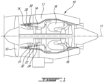
- Fig. 1 illustrates an aircraft engine depicted as a gas turbine engine 10 of a type preferably provided for use in subsonic flight, generally comprising in serial flow communication a fan 12, a compressor section 14 for pressurizing the air, a combustor 16 in which the compressed air is mixed with fuel and ignited for generating an annular stream of hot combustion gases, and a turbine section 18 for extracting energy from the combustion gases.
- the fan 12, the compressor section 14, and the turbine section 18 are rotatable about a central axis 11 of the gas turbine engine 10.
- the principles of the present disclosure may apply to any gas turbine engine such as turboprop and turboshaft gas turbine engines.
- the compressor section 14 includes one or more compressor rotors 22 and stators 24 in fluid communication with the rotors 22.
- the exemplary gas turbine engine 10 of Fig. 1 is a turbofan engine including the fan 12 through which ambient air is propelled. An airflow flowing between blades of the fan 12 is split between an engine core gaspath 15 and a bypass flow path 17 downstream of the fan 12.
- the gas turbine engine 10 has an engine casing 20 that circumferentially extends around the central axis 11. The core gaspath 15 is therefore located radially inwardly of the engine casing 20 relative to the central axis 11 and the bypass flow path 17 located radially outwardly of the engine casing 20 relative to the central axis 11.
- the compressor section 14 of the gas turbine engine 10 includes at least one compression stage having a tandem stator assembly 30 (which may be alternately referred to as a dual stator assembly), composed of two individual stators, namely a first stator 31 and a second stator 32 in immediate flow-wise succession (i.e. without any rotor therebetween); the second stator 32 located downstream of the first stator 31 relative to the air flow flowing in the core gaspath 15.
- the tandem stator assembly 30 is shown as being part of the first compression stage, that is it is located downstream of the fan 12 at the inlet of a core of the engine 10 and within the engine core gaspath 15.
- tandem stator assembly 30 may form part of other compression stages, such as those further downstream within the core of the gas turbine engine 10, either instead of or addition to being immediately downstream from the fan 12.
- the tandem stator assembly 30 may be used in a turbine stage of the turbine section 18.
- the tandem stator assembly 30 may be used in the bypass flow path 17.
- the core gaspath 15 is defined radially between an inner gaspath wall 21A, which may include vane platforms (not shown), and an outer gaspath wall 21B, which may include vane shroud (not shown).
- the outer gaspath wall 21B is located radially outwardly of the inner gaspath wall 21A relative to the central axis 11.
- the first stator 31 includes a first row of a plurality of first vanes 33 and the second stator 32 includes a second row of a plurality of second vanes 34.
- the first vanes 33 and the second vanes 34 are circumferentially distributed around the central axis 11.
- the first vanes 33 may be staggered relative to the second vanes 34.
- a circumferential position of each of the first vanes 33 may be between circumferential positions of two circumferentially adjacent ones of the second vanes 34. This configuration is shown more clearly in Fig. 3 .
- the first vanes 33 extend from first inner ends 33A at the inner gaspath wall 21A to first outer ends 33B at the outer gaspath wall 21B.
- the second vanes 34 extend from second inner ends 34A at the inner gaspath wall 21A to second outer ends 34B at the outer gaspath wall 21B.
- the first and second vanes 33, 34 may be overlapped.
- the first and second vanes 33, 34 may be cantilevered.
- a number of the first vanes 33 may be different (e.g., more or less) than a number of the second vanes 34.
- the first vanes 33 include first airfoils 35 having first leading edges 35A, first trailing edges 35B downstream of the first leading edges 35A, first pressure sides 35C ( Fig. 3 ), and first suction sides 35D ( Fig. 3 ) opposed the first pressure sides 35C.
- the first airfoils 35 extend in a direction having a radial component relative to the central axis 11 from the inner gaspath wall 21A to the outer gaspath wall 21B.
- the second vanes 34 include second airfoils 36 that extend in a direction having a radial component relative to the central axis 11 from the inner gaspath wall 21A to the outer gaspath wall 21B.
- the second airfoils 36 have second leading edges 36A, second trailing edges 36B downstream of the second leading edges 36A, second pressure sides 36C ( Fig. 3 ), and second suction sides 36D ( Fig. 3 ) opposed the second pressure sides 36C.
- the first airfoils 35 are offset from the second airfoils 36 such that the second leading edges 36A are located downstream of the first trailing edges 35B relative to the air flow flowing in the core gaspath 15. An axial offset is therefore defined between the second leading edges 36A and the first trailing edges 35B.
- the first airfoils 35 may be at least partially axially overlapped by the second airfoils 36 such that the second leading edges 36A are located upstream of the first trailing edges 36A.
- the second leading edges 36A may be axially aligned with the first trailing edges 36A.
- the core gaspath 15 extends toward the central axis 11 in the flow direction.
- both of the inner gaspath wall 21A and the outer gaspath wall 21B extend both axially and radially inwardly along a flow direction of the flow flowing in the core gaspath 15.
- the core gaspath 15 may extend toward the central axis 11 from a location downstream of the second stator 32. This falling gaspath configuration may create a reduced shroud static pressure that may further contribute in driving up the cross flow further up the second stator 32. Large cross flows can contribute to large stator losses, reduced stall range, and may be detrimental to performance of other components (e.g., rotors) downstream of the tandem stator 30.
- the tandem stator 30 includes depressions 40 that are defined in one or both of the inner gaspath wall 21A and the outer gaspath wall 21B.
- the depressions 40 extend from a baseline surface BS of the inner gaspath wall 21A and/or the outer gaspath wall 21B and away from the core gaspath 15.
- the baseline surface BS is a surface of the gaspath walls free of the depressions 40.
- the depressions 40 are located circumferentially between the first pressure sides 35C and the second suction sides 36D.
- the depressions 40 axially overlap both of the first airfoils 35 and the second airfoils 36 relative to the central axis 11.
- upstream ends of the depressions 40 are located upstream of the first trailing edges 35B and downstream ends of the depressions 40 are located downstream of the second leading edges 36A.
- the depressions 40 may overlap the first airfoils along half the length of the depression and may overlap the second airfoils along a remaining half of the length of the depressions 40.
- a major portion (e.g. 50% or more) of the depressions 40 may be located downstream of a mid-chord location of the first airfoils and upstream of a mid-chord location of the second airfoil.
- the depressions 40 may extend from upstream ends to downstream ends.
- the upstream ends may be located downstream of a mid-chord location of the first airfoils.
- the downstream ends may be located upstream of a mid-chord location of the second airfoils.
- Each of the depressions 40 may be entirely contained circumferentially between the pressure sides of the first airfoils and the suction sides of the second airfoils. In other words, areas between the suction sides of the first airfoils and the pressure sides of the second airfoils may remain free of the depressions.
- a ratio of a width W of the depressions 40 taken along a circumferential direction relative to the central axis 11 to a circumferential length C taken along the circumferential direction from the first trailing edges 35B to the second leading edges 36A may range from 0.3 to 0.9.
- a ratio of a length L of the depressions 40 taken along an axial direction relative to the central axis 11 to a total axial length Lt of the tandem stator 30 taken along the axial direction from the first leading edges 35A to the second trailing edges 36B may range from 0.15 to 0.75.
- a ratio of a depth D of the depressions 40 taken along a radial direction relative to the central axis 11 to a span S ( Fig.
- the first airfoils 35 may range from 0.05 to 0.1.
- the span S of the first airfoils 35 extends from the inner gaspath wall 21A to the outer gaspath wall 21B along the radial direction.
- the depth D may extend from the baseline surface BS to deepest locations of the depressions 40.
- a ratio of a distance A taken along the axial direction relative to the central axis 11 from the first leading edges 35A to upstream ends of the depressions 40 to an axial length of the first stator 31 along the axial direction from the first leading edges 35A to the first trailing edges 35B may range from 0.5 to 0.8.
- the width W of the depressions is maximal at an axial location registering with the first trailing edges 35B.
- the location of maximal width may be located at another location.
- the location where the depth D of the depressions 40 is maximal may be located downstream of first trailing edges 35B and near the throats of the second stator 32.
- the throats of the second stator 32 extend from the second leading edges 36A to the second suction sides 36D.
- the depressions 40 are located in the vicinity of the first trailing edges 35B and of the second leading edges 36A and may reduce pressure gradient; increase static pressure on area between the first trailing edges 35B and the second leading edges 36A, and may help to reduce pressure gradients across the second stator 32.
- the depressions 40 may be asymmetrical with respect to a plane containing the central axis 11 and intersecting a center of a space between the first vanes and the second vanes 33, 34.
- the depressions 40 may help in reducing radial streamlines, which may result in more streamlines following the general flow direction.
- the depressions 40 may reduce merging of stator wakes, which may result in less blockage compared to a configuration lacking the depressions 40.
- the depressions 40 may be used for a tandem stator in which an axial overlap is present between the first stator 31 and the second stator 32.
- the depressions 40 may help in reducing cross flow and secondary flow, which may improve stall margin and overall performance of the compressor.
- the downstream ends of the depressions 40 may be located proximate or downstream of throats of the second stator 32.
- the throats of the second stator 32 extend from the second leading edges 36A to the second suction sides 36D.
- downstream and upstream are all with reference to a direction of the main airflow through the core gaspath 15.
- the expression “fluid machine” includes compressors and turbines.
Abstract

Description
- The application relates generally to aircraft engines, such as gas turbine engines and, more particularly, to compressors and turbines of such engines.
- Tandem stators (i.e. two stator rows located in immediate succession) are sometimes used in compressors with very high pressure ratios, when high flow turning and/or high Mach number flow is required. However, when such compressors are operating at off-design conditions, there can be large distortions in the flow at the inlet to the first stator and/or downstream of the compressor rotor.
- Obtaining an acceptable performance and operating range from tandem stator designs can therefore be challenging, given that physical constraints on engine weight and overall compressor length can impose restrictions on stator length, number of stators, gas path size/shape, etc. Improvements are therefore sought.
- In one aspect, there is provided a fluid machine for an aircraft engine comprising: a first wall and a second wall circumferentially extending around a central axis; a gaspath defined between the first wall and the second wall; a rotor having blades circumferentially distributed around the central axis and extending across the gaspath, the rotor rotatable about the central axis; and a tandem stator in fluid communication with the rotor and having: a first row of first vanes extending across the gaspath and circumferentially distributed around the central axis, the first vanes having first airfoils including first leading edges, first trailing edges, first pressure sides and first suction sides opposed the first pressure sides, and a second row of second vanes downstream of the first vanes and extending across the gaspath, the second vanes circumferentially distributed about the central axis, the second vanes having second airfoils including second leading edges, second trailing edges, second pressure sides and second suction sides opposed the second pressure sides, the first vanes being circumferentially offset from the second vanes; and depressions defined in the first wall, the depressions extending from a baseline surface of the first wall away from the second wall, a depression of the depressions located circumferentially between a pressure side of the first pressure sides and a suction side of the second suction sides, the depressions axially overlapping the first airfoils and the second airfoils relative to the central axis.
- Optionally and in accordance with the above the fluid machine may include any of the following features, in any combinations.
- Optionally and in accordance with any of the above, a ratio of a width (W) of the depression taken along a circumferential direction relative to the central axis to a circumferential length (C) taken along the circumferential direction from the first trailing edges to the second leading edges ranges from 0.3 to 0.9.
- Optionally and in accordance with any of the above, a ratio of a length (L) of the depression taken along an axial direction relative to the central axis to a total axial length (Lt) of the tandem stator along the axial direction from the first leading edges to the second trailing edges ranges from 0.15 to 0.75.
- Optionally and in accordance with any of the above, a ratio of a depth (D) of the depression taken along a radial direction relative to the central axis to a span (S) of the first airfoils ranges from 0.05 to 0.1.
- Optionally and in accordance with any of the above, a ratio of a distance (A) taken along an axial direction relative to the central axis from the first leading edges to an upstream end of the depression to an axial length (Ls1) taken along the axial direction from the first leading edges to the first trailing edges ranges from 0.5 to 0.8.
- Optionally and in accordance with any of the above, the depression has a width taken in a circumferential direction relative to the central axis, the width being maximal at an axial location registering with the first trailing edges.
- Optionally and in accordance with any of the above, the first vanes are circumferentially offset from the second vanes such that a circumferential position of each of the first vanes is located between circumferential positions of two corresponding adjacent ones of the second vanes.
- Optionally and in accordance with any of the above, the first wall is located radially inwardly of the second wall relative to the central axis.
- Optionally and in accordance with any of the above, the first wall and the second wall extend towards the central axis in a flow direction of a flow flowing between the first vanes and the second vanes.
- Optionally and in accordance with any of the above, the fluid machine is a compressor.
- Optionally and in accordance with any of the above, the fluid machine is a turbine.
- In another aspect, there is provided an aircraft engine comprising: a compressor section having: a first wall and a second wall circumferentially extending around a central axis; a gaspath defined between the first wall and the second wall; a rotor having blades circumferentially distributed around the central axis and extending across the gaspath, the rotor rotatable about the central axis; and a tandem stator in fluid communication with the rotor and having: a first row of first vanes extending across the gaspath and circumferentially distributed around the central axis, the first vanes having first airfoils including first leading edges, first trailing edges, first pressure sides and first suction sides opposed the first pressure sides, and a second row of second vanes downstream of the first vanes and extending across the gaspath, the second vanes circumferentially distributed about the central axis, the second vanes having second airfoils including second leading edges, second trailing edges, second pressure sides and second suction sides opposed the second pressure sides, the first vanes being circumferentially offset from the second vanes; and depressions defined in the first wall, the depressions extending from a baseline surface of the first wall away from the second wall, a depression of the depressions located circumferentially between a pressure side of the first pressure sides and a suction side of the second suction sides, the depressions axially overlapping the first airfoils and the second airfoils relative to the central axis.
- Optionally and in accordance with any of the above the aircraft engine may include any of the following features, in any combinations.
- Optionally and in accordance with any of the above, a ratio of a width (W) of the depression taken along a circumferential direction relative to the central axis to a circumferential length (C) taken along the circumferential direction from the first trailing edges to the second leading edges ranges from 0.3 to 0.9.
- Optionally and in accordance with any of the above, a ratio of a length (L) of the depression taken along an axial direction relative to the central axis to a total axial length (Lt) of the tandem stator along the axial direction from the first leading edges and the second trailing edges ranges from 0.15 to 0.75.
- Optionally and in accordance with any of the above, a ratio of a depth (D) of the depression taken along a radial direction relative to the central axis to a span (S) of the first airfoils ranges from 0.05 to 0.1.
- Optionally and in accordance with any of the above, a ratio of a distance (A) taken along the axial direction from the first leading edges to an upstream end of the depression to an axial length (Ls1) taken along the axial direction from the first leading edges to the first trailing edges ranges from 0.5 to 0.8.
- Optionally and in accordance with any of the above, the depression has a width taken in the circumferential direction relative to the central axis, the width being maximal at an axial location registering with the first trailing edges.
- Optionally and in accordance with any of the above, the first vanes are circumferentially offset from the second vanes such that a circumferential position of each of the first vanes is located between circumferential positions of two corresponding adjacent ones of the second vanes.
- Optionally and in accordance with any of the above, the first wall is located radially inwardly of the second wall relative to the central axis.
- Optionally and in accordance with any of the above, the first wall and the second wall extend towards the central axis in a flow direction of a flow flowing between the first vanes and the second vanes.
- Reference is now made to the accompanying figures in which:
-
Fig. 1 is a schematic cross sectional view of an aircraft engine depicted as a gas turbine engine; -
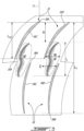
Fig. 2 is a schematic cross-sectional view of a tandem stator to be used in a compressor or a turbine of the gas turbine engine ofFig. 1 , the cross-sectional view taken on a plane containing a central axis of the gas turbine engine ofFig. 1 ; -
Fig. 3 is a schematic cross-sectional view of the tandem stator ofFig. 2 taken on a plane normal to a radial direction relative to the central axis of the gas turbine engine ofFig. 1 ; and -
Fig. 4 is a cross-sectional view of a depression defined in a gaspath wall of the tandem stator ofFig. 2 . -
Fig. 1 illustrates an aircraft engine depicted as agas turbine engine 10 of a type preferably provided for use in subsonic flight, generally comprising in serial flow communication afan 12, acompressor section 14 for pressurizing the air, acombustor 16 in which the compressed air is mixed with fuel and ignited for generating an annular stream of hot combustion gases, and aturbine section 18 for extracting energy from the combustion gases. Thefan 12, thecompressor section 14, and theturbine section 18 are rotatable about acentral axis 11 of thegas turbine engine 10. The principles of the present disclosure may apply to any gas turbine engine such as turboprop and turboshaft gas turbine engines. - The
compressor section 14 includes one ormore compressor rotors 22 andstators 24 in fluid communication with therotors 22. The exemplarygas turbine engine 10 ofFig. 1 is a turbofan engine including thefan 12 through which ambient air is propelled. An airflow flowing between blades of thefan 12 is split between anengine core gaspath 15 and abypass flow path 17 downstream of thefan 12. Thegas turbine engine 10 has anengine casing 20 that circumferentially extends around thecentral axis 11. Thecore gaspath 15 is therefore located radially inwardly of theengine casing 20 relative to thecentral axis 11 and thebypass flow path 17 located radially outwardly of theengine casing 20 relative to thecentral axis 11. - As will be described in further detail below, the
compressor section 14 of thegas turbine engine 10 includes at least one compression stage having a tandem stator assembly 30 (which may be alternately referred to as a dual stator assembly), composed of two individual stators, namely afirst stator 31 and asecond stator 32 in immediate flow-wise succession (i.e. without any rotor therebetween); thesecond stator 32 located downstream of thefirst stator 31 relative to the air flow flowing in thecore gaspath 15. In the embodiment depicted inFig. 1 , thetandem stator assembly 30 is shown as being part of the first compression stage, that is it is located downstream of thefan 12 at the inlet of a core of theengine 10 and within theengine core gaspath 15. It is to be understood, however, that the presenttandem stator assembly 30 may form part of other compression stages, such as those further downstream within the core of thegas turbine engine 10, either instead of or addition to being immediately downstream from thefan 12. In some embodiments, thetandem stator assembly 30 may be used in a turbine stage of theturbine section 18. Thetandem stator assembly 30 may be used in thebypass flow path 17. - Referring more particularly to
Fig. 2 , thecore gaspath 15 is defined radially between aninner gaspath wall 21A, which may include vane platforms (not shown), and anouter gaspath wall 21B, which may include vane shroud (not shown). Theouter gaspath wall 21B is located radially outwardly of theinner gaspath wall 21A relative to thecentral axis 11. - The
first stator 31 includes a first row of a plurality offirst vanes 33 and thesecond stator 32 includes a second row of a plurality ofsecond vanes 34. Thefirst vanes 33 and thesecond vanes 34 are circumferentially distributed around thecentral axis 11. Thefirst vanes 33 may be staggered relative to thesecond vanes 34. In other words, a circumferential position of each of thefirst vanes 33 may be between circumferential positions of two circumferentially adjacent ones of thesecond vanes 34. This configuration is shown more clearly inFig. 3 . Thefirst vanes 33 extend from firstinner ends 33A at theinner gaspath wall 21A to firstouter ends 33B at theouter gaspath wall 21B. Thesecond vanes 34 extend from secondinner ends 34A at theinner gaspath wall 21A to secondouter ends 34B at theouter gaspath wall 21B. The first andsecond vanes second vanes first vanes 33 may be different (e.g., more or less) than a number of thesecond vanes 34. - Referring to
Figs. 2-3 , thefirst vanes 33 includefirst airfoils 35 having first leadingedges 35A,first trailing edges 35B downstream of the first leadingedges 35A,first pressure sides 35C (Fig. 3 ), andfirst suction sides 35D (Fig. 3 ) opposed thefirst pressure sides 35C. Thefirst airfoils 35 extend in a direction having a radial component relative to thecentral axis 11 from theinner gaspath wall 21A to theouter gaspath wall 21B. Thesecond vanes 34 includesecond airfoils 36 that extend in a direction having a radial component relative to thecentral axis 11 from theinner gaspath wall 21A to theouter gaspath wall 21B. Thesecond airfoils 36 have secondleading edges 36A, second trailingedges 36B downstream of the secondleading edges 36A, second pressure sides 36C (Fig. 3 ), andsecond suction sides 36D (Fig. 3 ) opposed the second pressure sides 36C. - In the embodiment shown, the
first airfoils 35 are offset from thesecond airfoils 36 such that the secondleading edges 36A are located downstream of thefirst trailing edges 35B relative to the air flow flowing in thecore gaspath 15. An axial offset is therefore defined between the secondleading edges 36A and thefirst trailing edges 35B. In some embodiments, thefirst airfoils 35 may be at least partially axially overlapped by thesecond airfoils 36 such that the secondleading edges 36A are located upstream of thefirst trailing edges 36A. In some embodiments, the secondleading edges 36A may be axially aligned with thefirst trailing edges 36A. - It was observed that secondary flows exist in the
second stator 32 due to boundary layer build up from thefirst stator 31 and due to large pressure gradients required to turn the air flow in thesecond stator 32. Cross flow may be collected on the second suction sides 36D of thesecond airfoils 36 of thesecond stator 32 and radially outwardly along the surface before shedding above hub corner. Moreover, in the embodiment shown, thecore gaspath 15 extends toward thecentral axis 11 in the flow direction. In other words, both of theinner gaspath wall 21A and theouter gaspath wall 21B extend both axially and radially inwardly along a flow direction of the flow flowing in thecore gaspath 15. In some embodiments, thecore gaspath 15 may extend toward thecentral axis 11 from a location downstream of thesecond stator 32. This falling gaspath configuration may create a reduced shroud static pressure that may further contribute in driving up the cross flow further up thesecond stator 32. Large cross flows can contribute to large stator losses, reduced stall range, and may be detrimental to performance of other components (e.g., rotors) downstream of thetandem stator 30. - Still referring to
Figs. 2-3 , thetandem stator 30 includesdepressions 40 that are defined in one or both of theinner gaspath wall 21A and theouter gaspath wall 21B. Thedepressions 40 extend from a baseline surface BS of theinner gaspath wall 21A and/or theouter gaspath wall 21B and away from thecore gaspath 15. The baseline surface BS is a surface of the gaspath walls free of thedepressions 40. As shown inFig. 3 , thedepressions 40 are located circumferentially between thefirst pressure sides 35C and the second suction sides 36D. Thedepressions 40 axially overlap both of thefirst airfoils 35 and thesecond airfoils 36 relative to thecentral axis 11. In other words, and in the depicted embodiment, upstream ends of thedepressions 40 are located upstream of thefirst trailing edges 35B and downstream ends of thedepressions 40 are located downstream of the secondleading edges 36A. - The
depressions 40 may overlap the first airfoils along half the length of the depression and may overlap the second airfoils along a remaining half of the length of thedepressions 40. A major portion (e.g. 50% or more) of thedepressions 40 may be located downstream of a mid-chord location of the first airfoils and upstream of a mid-chord location of the second airfoil. Thedepressions 40 may extend from upstream ends to downstream ends. The upstream ends may be located downstream of a mid-chord location of the first airfoils. The downstream ends may be located upstream of a mid-chord location of the second airfoils. Each of thedepressions 40 may be entirely contained circumferentially between the pressure sides of the first airfoils and the suction sides of the second airfoils. In other words, areas between the suction sides of the first airfoils and the pressure sides of the second airfoils may remain free of the depressions. - Referring more particularly to
Figs. 3-4 , a ratio of a width W of thedepressions 40 taken along a circumferential direction relative to thecentral axis 11 to a circumferential length C taken along the circumferential direction from thefirst trailing edges 35B to the secondleading edges 36A may range from 0.3 to 0.9. A ratio of a length L of thedepressions 40 taken along an axial direction relative to thecentral axis 11 to a total axial length Lt of thetandem stator 30 taken along the axial direction from the firstleading edges 35A to thesecond trailing edges 36B may range from 0.15 to 0.75. A ratio of a depth D of thedepressions 40 taken along a radial direction relative to thecentral axis 11 to a span S (Fig. 2 ) of thefirst airfoils 35 may range from 0.05 to 0.1. The span S of thefirst airfoils 35 extends from theinner gaspath wall 21A to theouter gaspath wall 21B along the radial direction. The depth D may extend from the baseline surface BS to deepest locations of thedepressions 40. A ratio of a distance A taken along the axial direction relative to thecentral axis 11 from the firstleading edges 35A to upstream ends of thedepressions 40 to an axial length of thefirst stator 31 along the axial direction from the firstleading edges 35A to thefirst trailing edges 35B may range from 0.5 to 0.8. In the embodiment shown, the width W of the depressions is maximal at an axial location registering with thefirst trailing edges 35B. In some embodiments, the location of maximal width may be located at another location. The location where the depth D of thedepressions 40 is maximal may be located downstream of first trailingedges 35B and near the throats of thesecond stator 32. The throats of thesecond stator 32 extend from the secondleading edges 36A to the second suction sides 36D. - The
depressions 40 are located in the vicinity of thefirst trailing edges 35B and of the secondleading edges 36A and may reduce pressure gradient; increase static pressure on area between thefirst trailing edges 35B and the secondleading edges 36A, and may help to reduce pressure gradients across thesecond stator 32. Thedepressions 40 may be asymmetrical with respect to a plane containing thecentral axis 11 and intersecting a center of a space between the first vanes and thesecond vanes depressions 40 may help in reducing radial streamlines, which may result in more streamlines following the general flow direction. Thedepressions 40 may reduce merging of stator wakes, which may result in less blockage compared to a configuration lacking thedepressions 40. Thedepressions 40 may be used for a tandem stator in which an axial overlap is present between thefirst stator 31 and thesecond stator 32. Thedepressions 40 may help in reducing cross flow and secondary flow, which may improve stall margin and overall performance of the compressor. In some embodiments, the downstream ends of thedepressions 40 may be located proximate or downstream of throats of thesecond stator 32. The throats of thesecond stator 32 extend from the secondleading edges 36A to the second suction sides 36D. - The terms "downstream" and "upstream" as used herein are all with reference to a direction of the main airflow through the
core gaspath 15. In the context of the present disclosure, the expression "fluid machine" includes compressors and turbines. - The embodiments described in this document provide non-limiting examples of possible implementations of the present technology. Upon review of the present disclosure, a person of ordinary skill in the art will recognize that changes may be made to the embodiments described herein without departing from the scope of the present technology. Yet further modifications could be implemented by a person of ordinary skill in the art in view of the present disclosure, which modifications would be within the scope of the present technology.
Claims (12)
- A fluid machine for an aircraft engine (10) comprising:a first wall (21A) and a second wall (21B) circumferentially extending around a central axis (11);a gaspath (15) defined between the first wall (21A) and the second wall (21B);a rotor (22) having blades circumferentially distributed around the central axis (11) and extending across the gaspath (15), the rotor rotatable about the central axis (11); anda tandem stator (30) in fluid communication with the rotor (22) and having:a first row of first vanes (33) extending across the gaspath (15) and circumferentially distributed around the central axis (11), the first vanes (33) having first airfoils (35) including first leading edges (35A), first trailing edges (35B), first pressure sides (35C) and first suction sides (35D) opposed to the first pressure sides (35C); anda second row of second vanes (34) downstream of the first vanes (33) and extending across the gaspath (15), the second vanes (34) circumferentially distributed about the central axis (11), the second vanes (34) having second airfoils (36) including second leading edges (36A), second trailing edges (36B), second pressure sides (36C) and second suction sides (36D) opposed to the second pressure sides (36C), the first vanes (33) being circumferentially offset from the second vanes (34); anddepressions (40) defined in the first wall (21A), the depressions (40) extending from a baseline surface (BS) of the first wall (21A) away from the second wall (21B), a depression (40) of the depressions (40) located circumferentially between a pressure side (35C) of the first pressure sides (35C) and a suction side (35D) of the second suction sides (36D), the depressions (40) axially overlapping the first airfoils (35) and the second airfoils (36) relative to the central axis (11).
- The fluid machine of claim 1, wherein a ratio of a width (W) of the depression (40) taken along a circumferential direction relative to the central axis (11) to a circumferential length (C) taken along the circumferential direction from the first trailing edges (35B) to the second leading edges (36B) ranges from 0.3 to 0.9.
- The fluid machine of claims 1 or 2, wherein a ratio of a length (L) of the depression (40) taken along an axial direction relative to the central axis (11) to a total axial length (Lt) of the tandem stator (30) along the axial direction from the first leading edges (35B) to the second trailing edges (36B) ranges from 0.15 to 0.75.
- The fluid machine of any of claims 1 to 3, wherein a ratio of a depth (D) of the depression (40) taken along a radial direction relative to the central axis (11) to a span (S) of the first airfoils (35) ranges from 0.05 to 0.1.
- The fluid machine of any preceding claim, wherein a ratio of a distance (A) taken along an axial direction relative to the central axis (11) from the first leading edges (35A) to an upstream end of the depression (40) to an axial length (Ls1) taken along the axial direction from the first leading edges (35A) to the first trailing edges (35B) ranges from 0.5 to 0.8.
- The fluid machine of any preceding claim, wherein the depression (40) has a width taken in a circumferential direction relative to the central axis (11), the width being maximal at an axial location registering with the first trailing edges (35B).
- The fluid machine of any preceding claim, wherein the first vanes (33) are circumferentially offset from the second vanes (34) such that a circumferential position of each of the first vanes (33) is located between circumferential positions of two corresponding adjacent ones of the second vanes (34).
- The fluid machine of any preceding claim, wherein the first wall (21A) is located radially inwardly of the second wall (21B) relative to the central axis (11).
- The fluid machine of any preceding claim, wherein the first wall (21A) and the second wall (21B) extend towards the central axis (11) in a flow direction of a flow flowing between the first vanes (33) and the second vanes (34).
- The fluid machine of any preceding claim, wherein the fluid machine is a compressor (14).
- The fluid machine of any one of claims 1 to 9, wherein the fluid machine is a turbine (18).
- An aircraft engine (10) comprising a compressor section (14) having a fluid machine as defined in any of claims 1 to 9.
Applications Claiming Priority (1)
| Application Number | Priority Date | Filing Date | Title |
|---|---|---|---|
| US17/466,187 US11415012B1 (en) | 2021-09-03 | 2021-09-03 | Tandem stator with depressions in gaspath wall |
Publications (1)
| Publication Number | Publication Date |
|---|---|
| EP4144958A1 true EP4144958A1 (en) | 2023-03-08 |
Family
ID=82802858
Family Applications (1)
| Application Number | Title | Priority Date | Filing Date |
|---|---|---|---|
| EP22193968.9A Pending EP4144958A1 (en) | 2021-09-03 | 2022-09-05 | Fluid machine for an aircraft engine and aircraft engine |
Country Status (3)
| Country | Link |
|---|---|
| US (1) | US11415012B1 (en) |
| EP (1) | EP4144958A1 (en) |
| CA (1) | CA3170968A1 (en) |
Citations (2)
| Publication number | Priority date | Publication date | Assignee | Title |
|---|---|---|---|---|
| US20140090380A1 (en) * | 2012-09-28 | 2014-04-03 | United Technologies Corporation | Endwall Controuring |
| US20150252674A1 (en) * | 2014-03-10 | 2015-09-10 | Rolls-Royce Deutschland Ltd & Co Kg | Method for producing a tandem blade wheel for a jet engine and tandem blade wheel |
Family Cites Families (17)
| Publication number | Priority date | Publication date | Assignee | Title |
|---|---|---|---|---|
| JP4929193B2 (en) * | 2008-01-21 | 2012-05-09 | 三菱重工業株式会社 | Turbine cascade endwall |
| JP5291355B2 (en) * | 2008-02-12 | 2013-09-18 | 三菱重工業株式会社 | Turbine cascade endwall |
| US8647067B2 (en) * | 2008-12-09 | 2014-02-11 | General Electric Company | Banked platform turbine blade |
| US8403645B2 (en) * | 2009-09-16 | 2013-03-26 | United Technologies Corporation | Turbofan flow path trenches |
| US8684684B2 (en) | 2010-08-31 | 2014-04-01 | General Electric Company | Turbine assembly with end-wall-contoured airfoils and preferenttial clocking |
| WO2014105102A1 (en) * | 2012-12-28 | 2014-07-03 | United Technologies Corporation | Platform with curved edges adjacent suction side of airfoil |
| DE102014205226A1 (en) | 2014-03-20 | 2015-09-24 | Rolls-Royce Deutschland Ltd & Co Kg | Blade row group |
| DE102014205235A1 (en) * | 2014-03-20 | 2015-09-24 | Rolls-Royce Deutschland Ltd & Co Kg | Blade row group |
| US10287901B2 (en) | 2014-12-08 | 2019-05-14 | United Technologies Corporation | Vane assembly of a gas turbine engine |
| US10221710B2 (en) * | 2016-02-09 | 2019-03-05 | General Electric Company | Turbine nozzle having non-axisymmetric endwall contour (EWC) and profile |
| US10590781B2 (en) * | 2016-12-21 | 2020-03-17 | General Electric Company | Turbine engine assembly with a component having a leading edge trough |
| EP3401504A1 (en) * | 2017-05-10 | 2018-11-14 | MTU Aero Engines GmbH | Blade grid |
| EP3404210A1 (en) * | 2017-05-15 | 2018-11-21 | MTU Aero Engines GmbH | Blade cascade segment for a turbomachine with non-axisymmetric platform surface, corresponding blade cascade, blade channel, platform, and turbomachine |
| JP7250813B2 (en) * | 2018-03-30 | 2023-04-03 | シーメンス エナジー グローバル ゲゼルシャフト ミット ベシュレンクテル ハフツング ウント コンパニー コマンディートゲゼルシャフト | Turbine stage platform with endwall profile with corrugated mating surfaces |
| JP7230058B2 (en) | 2018-03-30 | 2023-02-28 | シーメンス エナジー グローバル ゲゼルシャフト ミット ベシュレンクテル ハフツング ウント コンパニー コマンディートゲゼルシャフト | Endwall contouring of conical endwalls |
| US10890072B2 (en) * | 2018-04-05 | 2021-01-12 | Raytheon Technologies Corporation | Endwall contour |
| US11033992B2 (en) | 2018-10-05 | 2021-06-15 | Pratt & Whitney Canada Corp. | Double row compressor stators |
-
2021
- 2021-09-03 US US17/466,187 patent/US11415012B1/en active Active
-
2022
- 2022-08-23 CA CA3170968A patent/CA3170968A1/en active Pending
- 2022-09-05 EP EP22193968.9A patent/EP4144958A1/en active Pending
Patent Citations (2)
| Publication number | Priority date | Publication date | Assignee | Title |
|---|---|---|---|---|
| US20140090380A1 (en) * | 2012-09-28 | 2014-04-03 | United Technologies Corporation | Endwall Controuring |
| US20150252674A1 (en) * | 2014-03-10 | 2015-09-10 | Rolls-Royce Deutschland Ltd & Co Kg | Method for producing a tandem blade wheel for a jet engine and tandem blade wheel |
Also Published As
| Publication number | Publication date |
|---|---|
| CA3170968A1 (en) | 2023-03-03 |
| US11415012B1 (en) | 2022-08-16 |
Similar Documents
| Publication | Publication Date | Title |
|---|---|---|
| US10822957B2 (en) | Fillet optimization for turbine airfoil | |
| US10436038B2 (en) | Turbine engine with an airfoil having a tip shelf outlet | |
| EP2778427B1 (en) | Compressor bleed self-recirculating system | |
| EP2935789B2 (en) | Airfoil assembly with paired endwall contouring | |
| CA2844552C (en) | Compressor shroud reverse bleed holes | |
| EP3165715A1 (en) | Turbine blade | |
| US10267161B2 (en) | Gas turbine engine with fillet film holes | |
| US20210372288A1 (en) | Compressor stator with leading edge fillet | |
| EP4144958A1 (en) | Fluid machine for an aircraft engine and aircraft engine | |
| WO2018128609A1 (en) | Seal assembly between a hot gas path and a rotor disc cavity | |
| WO2018004766A1 (en) | Airfoil and blade for a turbine engine, and corresponding method of flowing a cooling fluid | |
| EP4144959A1 (en) | Fluid machine for an aircraft engine and aircraft engine | |
| US10982554B2 (en) | Tip shroud for a turbine engine | |
| US11639666B2 (en) | Stator with depressions in gaspath wall adjacent leading edges | |
| US11939880B1 (en) | Airfoil assembly with flow surface | |
| CN113389599B (en) | Turbine engine with high acceleration and low blade turning airfoils | |
| US11933193B2 (en) | Turbine engine with an airfoil having a set of dimples | |
| US20240011407A1 (en) | Turbine engine with a rotating blade having a fin | |
| US11401835B2 (en) | Turbine center frame |
Legal Events
| Date | Code | Title | Description |
|---|---|---|---|
| PUAI | Public reference made under article 153(3) epc to a published international application that has entered the european phase |
Free format text: ORIGINAL CODE: 0009012 |
|
| STAA | Information on the status of an ep patent application or granted ep patent |
Free format text: STATUS: THE APPLICATION HAS BEEN PUBLISHED |
|
| AK | Designated contracting states |
Kind code of ref document: A1 Designated state(s): AL AT BE BG CH CY CZ DE DK EE ES FI FR GB GR HR HU IE IS IT LI LT LU LV MC MK MT NL NO PL PT RO RS SE SI SK SM TR |
|
| STAA | Information on the status of an ep patent application or granted ep patent |
Free format text: STATUS: REQUEST FOR EXAMINATION WAS MADE |
|
| 17P | Request for examination filed |
Effective date: 20230907 |
|
| RBV | Designated contracting states (corrected) |
Designated state(s): AL AT BE BG CH CY CZ DE DK EE ES FI FR GB GR HR HU IE IS IT LI LT LU LV MC MK MT NL NO PL PT RO RS SE SI SK SM TR |
|
| GRAP | Despatch of communication of intention to grant a patent |
Free format text: ORIGINAL CODE: EPIDOSNIGR1 |
|
| STAA | Information on the status of an ep patent application or granted ep patent |
Free format text: STATUS: GRANT OF PATENT IS INTENDED |
|
| INTG | Intention to grant announced |
Effective date: 20231212 |
|
| GRAS | Grant fee paid |
Free format text: ORIGINAL CODE: EPIDOSNIGR3 |
|
| GRAA | (expected) grant |
Free format text: ORIGINAL CODE: 0009210 |
|
| STAA | Information on the status of an ep patent application or granted ep patent |
Free format text: STATUS: THE PATENT HAS BEEN GRANTED |