EP4144956A1 - Rotary manifold for a cohesion-type drive - Google Patents
Rotary manifold for a cohesion-type drive Download PDFInfo
- Publication number
- EP4144956A1 EP4144956A1 EP22184133.1A EP22184133A EP4144956A1 EP 4144956 A1 EP4144956 A1 EP 4144956A1 EP 22184133 A EP22184133 A EP 22184133A EP 4144956 A1 EP4144956 A1 EP 4144956A1
- Authority
- EP
- European Patent Office
- Prior art keywords
- manifold
- ports
- ductwork
- fluid
- header
- Prior art date
- Legal status (The legal status is an assumption and is not a legal conclusion. Google has not performed a legal analysis and makes no representation as to the accuracy of the status listed.)
- Granted
Links
- 239000012530 fluid Substances 0.000 claims abstract description 249
- 238000004891 communication Methods 0.000 claims abstract description 65
- 238000002955 isolation Methods 0.000 claims abstract description 21
- 230000002093 peripheral effect Effects 0.000 claims description 9
- 230000006835 compression Effects 0.000 description 181
- 238000007906 compression Methods 0.000 description 181
- 230000001939 inductive effect Effects 0.000 description 20
- 230000035882 stress Effects 0.000 description 17
- 238000012546 transfer Methods 0.000 description 12
- 230000003750 conditioning effect Effects 0.000 description 8
- 238000000034 method Methods 0.000 description 8
- 238000007599 discharging Methods 0.000 description 7
- 238000001816 cooling Methods 0.000 description 6
- 230000007423 decrease Effects 0.000 description 6
- 230000003247 decreasing effect Effects 0.000 description 4
- 238000004873 anchoring Methods 0.000 description 3
- 239000000567 combustion gas Substances 0.000 description 3
- 238000002485 combustion reaction Methods 0.000 description 3
- 239000004020 conductor Substances 0.000 description 3
- 238000010276 construction Methods 0.000 description 3
- 238000013461 design Methods 0.000 description 3
- 239000007789 gas Substances 0.000 description 3
- 230000008602 contraction Effects 0.000 description 2
- 238000005457 optimization Methods 0.000 description 2
- 238000010146 3D printing Methods 0.000 description 1
- 230000000712 assembly Effects 0.000 description 1
- 238000000429 assembly Methods 0.000 description 1
- 238000005266 casting Methods 0.000 description 1
- 238000009792 diffusion process Methods 0.000 description 1
- 239000000446 fuel Substances 0.000 description 1
- 239000000463 material Substances 0.000 description 1
- 239000000203 mixture Substances 0.000 description 1
- 238000012986 modification Methods 0.000 description 1
- 230000004048 modification Effects 0.000 description 1
- 230000001681 protective effect Effects 0.000 description 1
- 230000001172 regenerating effect Effects 0.000 description 1
- 125000006850 spacer group Chemical group 0.000 description 1
- 230000008646 thermal stress Effects 0.000 description 1
Images


Classifications
-
- F—MECHANICAL ENGINEERING; LIGHTING; HEATING; WEAPONS; BLASTING
- F01—MACHINES OR ENGINES IN GENERAL; ENGINE PLANTS IN GENERAL; STEAM ENGINES
- F01D—NON-POSITIVE DISPLACEMENT MACHINES OR ENGINES, e.g. STEAM TURBINES
- F01D1/00—Non-positive-displacement machines or engines, e.g. steam turbines
- F01D1/34—Non-positive-displacement machines or engines, e.g. steam turbines characterised by non-bladed rotor, e.g. with drilled holes
- F01D1/36—Non-positive-displacement machines or engines, e.g. steam turbines characterised by non-bladed rotor, e.g. with drilled holes using fluid friction
-
- F—MECHANICAL ENGINEERING; LIGHTING; HEATING; WEAPONS; BLASTING
- F01—MACHINES OR ENGINES IN GENERAL; ENGINE PLANTS IN GENERAL; STEAM ENGINES
- F01D—NON-POSITIVE DISPLACEMENT MACHINES OR ENGINES, e.g. STEAM TURBINES
- F01D1/00—Non-positive-displacement machines or engines, e.g. steam turbines
- F01D1/32—Non-positive-displacement machines or engines, e.g. steam turbines with pressure velocity transformation exclusively in rotor, e.g. the rotor rotating under the influence of jets issuing from the rotor, e.g. Heron turbines
-
- F—MECHANICAL ENGINEERING; LIGHTING; HEATING; WEAPONS; BLASTING
- F01—MACHINES OR ENGINES IN GENERAL; ENGINE PLANTS IN GENERAL; STEAM ENGINES
- F01D—NON-POSITIVE DISPLACEMENT MACHINES OR ENGINES, e.g. STEAM TURBINES
- F01D1/00—Non-positive-displacement machines or engines, e.g. steam turbines
- F01D1/34—Non-positive-displacement machines or engines, e.g. steam turbines characterised by non-bladed rotor, e.g. with drilled holes
-
- F—MECHANICAL ENGINEERING; LIGHTING; HEATING; WEAPONS; BLASTING
- F01—MACHINES OR ENGINES IN GENERAL; ENGINE PLANTS IN GENERAL; STEAM ENGINES
- F01L—CYCLICALLY OPERATING VALVES FOR MACHINES OR ENGINES
- F01L1/00—Valve-gear or valve arrangements, e.g. lift-valve gear
- F01L1/32—Valve-gear or valve arrangements, e.g. lift-valve gear characterised by the provision of means for rotating lift valves, e.g. to diminish wear
-
- F—MECHANICAL ENGINEERING; LIGHTING; HEATING; WEAPONS; BLASTING
- F01—MACHINES OR ENGINES IN GENERAL; ENGINE PLANTS IN GENERAL; STEAM ENGINES
- F01L—CYCLICALLY OPERATING VALVES FOR MACHINES OR ENGINES
- F01L1/00—Valve-gear or valve arrangements, e.g. lift-valve gear
- F01L1/34—Valve-gear or valve arrangements, e.g. lift-valve gear characterised by the provision of means for changing the timing of the valves without changing the duration of opening and without affecting the magnitude of the valve lift
-
- F—MECHANICAL ENGINEERING; LIGHTING; HEATING; WEAPONS; BLASTING
- F01—MACHINES OR ENGINES IN GENERAL; ENGINE PLANTS IN GENERAL; STEAM ENGINES
- F01L—CYCLICALLY OPERATING VALVES FOR MACHINES OR ENGINES
- F01L1/00—Valve-gear or valve arrangements, e.g. lift-valve gear
- F01L1/36—Valve-gear or valve arrangements, e.g. lift-valve gear peculiar to machines or engines of specific type other than four-stroke cycle
-
- F—MECHANICAL ENGINEERING; LIGHTING; HEATING; WEAPONS; BLASTING
- F02—COMBUSTION ENGINES; HOT-GAS OR COMBUSTION-PRODUCT ENGINE PLANTS
- F02C—GAS-TURBINE PLANTS; AIR INTAKES FOR JET-PROPULSION PLANTS; CONTROLLING FUEL SUPPLY IN AIR-BREATHING JET-PROPULSION PLANTS
- F02C3/00—Gas-turbine plants characterised by the use of combustion products as the working fluid
- F02C3/14—Gas-turbine plants characterised by the use of combustion products as the working fluid characterised by the arrangement of the combustion chamber in the plant
- F02C3/16—Gas-turbine plants characterised by the use of combustion products as the working fluid characterised by the arrangement of the combustion chamber in the plant the combustion chambers being formed at least partly in the turbine rotor or in an other rotating part of the plant
- F02C3/165—Gas-turbine plants characterised by the use of combustion products as the working fluid characterised by the arrangement of the combustion chamber in the plant the combustion chambers being formed at least partly in the turbine rotor or in an other rotating part of the plant the combustion chamber contributes to the driving force by creating reactive thrust
Landscapes
- Engineering & Computer Science (AREA)
- Mechanical Engineering (AREA)
- General Engineering & Computer Science (AREA)
- Chemical & Material Sciences (AREA)
- Combustion & Propulsion (AREA)
- Structures Of Non-Positive Displacement Pumps (AREA)
Abstract
Description
- This application claims the benefit of
United States Provisional Application No. 62/426,109, filed on November 23, 2016 United States Provisional Application No. 62/426,122, filed on November 23, 2016 - The disclosure relates to cohesion-type drives. More specifically, the disclosure relates to manifolds for rotor assemblies of cohesion-type drives.
-
U.S. Pat. No. 3,899,875 (Oklejas et al .) discloses a gas turbine. The turbine comprises a casing and a rotor mounted on bearings within the casing. The rotor is of a Tesla-type configuration. Means are provided on the rotor to conduct cooling air to alternate spaces between sets of disc-like blades of the rotor and to conduct a working fluid to opposite alternate spaces between the blades. The air cools the blades and is correspondingly heated. A collecting chamber receives the heated air and conducts it ultimately to a combustion chamber. -
U.S. Pat. No. 3,999,377 (Oklejas et al .) discloses a tesla-type turbine including turbine blade cooling means. The turbine blades define a plurality of alternate spaces, with an air-conducting cooling space positioned between each pair of turbine or working spaces. While hot working gas expands between blades in the turbine spaces, cooling air flows in the opposite direction in the adjacent cooling spaces to cool the turbine blades. The disclosed turbine construction provides for axial air inflow and radial air outflow, with axial exhaust of working gas. After being heated by contact with the turbine blades, the cooling air is utilized in the combustion chamber of the turbine. -
U.S. Pat. No. 3,007,311 (Amero ) discloses an apparatus including a plurality of spaced discs coaxially positioned on a hub and secured against rotation about the hub, such discs defining a series of spaces extending along the hub, and a pair of isolated passageways axially disposed in the hub having alternate radial communication with the series of spaces, one of such passageways constituting an intake manifold and the other of such passageways constituting the exhaust manifold. - The following summary is intended to introduce the reader to various aspects of the applicant's teaching, but not to define any invention.
- According to some aspects, a cohesion-type drive includes (a) a casing; (b) a shaft rotatably supported in the casing for rotation about a drive axis in a circumferential forward direction; and (c) a disc pack supported in the casing coaxial with the shaft and fixed to rotate therewith. The disc pack includes a plurality of discs spaced axially apart from one another by disc spaces. The disc spaces include a plurality of compression chambers and a plurality of turbine chambers, with the turbine chambers alternating axially with and in fluid isolation of the compression chambers. The drive further includes (d) a hub manifold in the casing radially inward of the disc pack and fixed to rotate with the shaft about the drive axis. The hub manifold includes a hub body coaxial with the drive axis, a compression chamber inlet ductwork internal the hub body and in fluid communication with the compression chambers for conducting a first fluid into the compression chambers to compress the first fluid during rotation of the disc pack in the forward direction, and a turbine chamber outlet ductwork internal the hub body and in fluid communication with the turbine chambers for evacuating a second fluid from the turbine chambers. The turbine chamber outlet ductwork is in fluid isolation of the compression chamber inlet ductwork. The drive further includes a shroud manifold in the casing radially outward of the disc pack. The shroud manifold includes a compression chamber outlet ductwork in fluid communication with the compression chambers for evacuating the first fluid from the compression chambers, and a turbine chamber inlet ductwork in fluid communication with the turbine chambers for conducting the second fluid into the turbine chambers to urge rotation of the disc pack in the forward direction. The turbine chamber inlet ductwork in fluid isolation of the compression chamber outlet ductwork.
- In some examples, the hub body includes a body first endface, a body second endface axially opposite the body first endface, and a body outer surface extending between the body first and second endfaces and directed radially outwardly toward the disc pack. The disc spaces are bounded radially by the body outer surface. The compression chamber inlet ductwork includes a plurality of compression chamber inlet ports open to the body outer surface for discharging the first fluid from the compression chamber inlet ductwork into the compression chambers, and the turbine chamber outlet ductwork includes a plurality of turbine chamber outlet ports open to the body outer surface for evacuating the second fluid from the turbine chambers and into the turbine chamber outlet ductwork.
- In some examples, the compression chamber inlet ductwork includes a plurality of circumferentially spaced apart headers in fluid communication with the compression chamber inlet ports. Each header extends along a header centerline between a header first end open to the body first endface for receiving the first fluid and a header second end spaced axially apart from the header first end toward the body second endface.
- In some examples, the header centerline extends helically about the drive axis in the circumferential forward direction from the header first end to the header second end.
- In some examples, each header has a cross sectional area perpendicular to the drive axis, and the cross-sectional area of each header decreases along the header centerline from the header first end toward the header second end.
- In some examples, the hub manifold includes a plurality of aerodynamic features extending at least partially across the header first ends and fixed to rotate with the hub body for conditioning flow of the first fluid entering the header first ends. In some examples, the aerodynamic features comprise circumferentially spaced apart airfoils extending radially across respective header first ends.
- In some examples, the compression chamber inlet ductwork includes a plurality of inlet conduits for conducting the first fluid from the headers to the compression chamber inlet ports, and each inlet conduit extends along an inlet conduit centerline between a respective compression chamber inlet port and an inlet conduit intake end open to a respective header.
- In some examples, the inlet conduit centerline curves circumferentially between the chamber inlet port and the inlet conduit intake end. In some examples, the inlet conduit centerline extends from the inlet conduit intake end to the compression chamber inlet port in a circumferential reverse direction opposite the forward direction for directing fluid passing radially outwardly through the inlet conduit and into a respective compression chamber in the reverse direction.
- In some examples, the hub body includes a body inner surface radially opposite the body outer surface, and a manifold bore coaxial with the drive axis and bounded radially by the body inner surface. In some examples, the turbine chamber outlet ductwork includes a plurality of outlet conduits for conducting the second fluid from the turbine chamber outlet ports to a fluid evacuation space provided in the manifold bore. Each outlet conduit extends along an outlet conduit centerline between a respective turbine chamber outlet port and an outlet conduit discharge end open to the body inner surface and in fluid communication with the evacuation space.
- In some examples, the outlet conduit centerline curves circumferentially between the turbine chamber outlet port and the outlet conduit discharge end. In some examples, the outlet conduit centerline extends from the turbine chamber outlet port to the outlet conduit discharge end in the circumferential forward direction for directing the second fluid passing radially inwardly through the outlet conduit in the forward direction.
- In some examples, compression chamber inlet ports are arranged in axially spaced apart inlet sets, and the compression chamber inlet ports in each set are spaced circumferentially apart from one another about the drive axis and open to a respective compression chamber. In some examples, the turbine chamber outlet ports are arranged in axially spaced apart outlet sets alternating axially with the inlet sets, and the turbine chamber outlet ports in each set are spaced circumferentially apart from one another about the drive axis and open to a respective turbine chamber.
- In some examples, the hub manifold includes a plurality of axially spaced apart circumferential grooves in the hub body outer surface, each groove receiving a radially inner peripheral edge of a respective disc.
- In some examples, the body outer surface is spaced radially apart from the drive axis by a radius, the radius decreasing along the drive axis from the body first endface to the body second endface.
- In some examples, the hub body includes a core coaxial with the drive axis and through which at least a portion of the compression chamber inlet ductwork and the turbine chamber outlet ductwork passes, and a frame mounted to the core for exerting an inwardly directed force on the core to regulate a stress distribution therein during operation.
- In some examples, the core has a radially outwardly directed core outer surface, and the frame includes an outer sleeve mounted over the core and in engagement with the core outer surface for inducing radial compression of the core during operation.
- In some examples, the core includes a radially inwardly directed core inner surface radially opposite the core outer surface, and a core bore coaxial with the drive axis and bounded radially by the core inner surface, and the frame includes an inner sleeve in the core bore and in engagement with the core inner surface. The inner and outer sleeves are anchored to one another for inducing radial compression of the core during operation.
- In some examples, the core has a core first endface and a core second endface axially opposite the core first endface, and the frame includes a first end cap in engagement with the core first endface and a second end cap in engagement with the core second endface. The first and second end caps are anchored to one another for inducing axial compression of the core during operation.
- In some examples, at least a portion of the hub body is formed of a thermally conductive material for conductively transferring heat between the first fluid passing through the compression chamber inlet ductwork and the second fluid passing through the turbine chamber outlet ductwork.
- In some examples, the shroud manifold is fixed to rotate with the shaft about the drive axis, and includes a shroud body coaxial with the drive axis, and the turbine chamber inlet ductwork and the compression chamber outlet ductwork are internal the shroud body.
- According to some aspects, a cohesion-type drive includes (a) a casing; (b) a shaft rotatably supported in the casing for rotation about a drive axis in a circumferential forward direction; and (c) a disc pack supported in the casing coaxial with the shaft and fixed to rotate therewith. The disc pack includes a plurality of discs spaced axially apart from one another by disc spaces. The disc spaces comprise a plurality of compression chambers and a plurality of turbine chambers, with the turbine chambers alternating axially with and in fluid isolation of the compression chambers. The drive further includes (d) a hub manifold in the casing radially inward of the disc pack. The hub manifold includes a compression chamber inlet ductwork in fluid communication with the compression chambers for conducting a first fluid into the compression chambers to compress the first fluid during rotation of the disc pack in the forward direction, and a turbine chamber outlet ductwork in fluid communication with the turbine chambers for evacuating a second fluid from the turbine chambers. The turbine chamber outlet ductwork is in fluid isolation of the compression chamber inlet ductwork. The drive further includes (e) a shroud manifold in the casing radially outward of the disc pack and fixed to rotate with the shaft about the drive axis. The shroud manifold includes: a shroud body coaxial with the drive axis, a compression chamber outlet ductwork internal the shroud body and in fluid communication with the compression chambers for evacuating the first fluid from the compression chambers, and a turbine chamber inlet ductwork internal the shroud body and in fluid communication with the turbine chambers for conducting the second fluid into the turbine chambers to urge rotation of the disc pack in the forward direction. The turbine chamber inlet ductwork is in fluid isolation of the compression chamber outlet ductwork.
- In some examples, the shroud body includes a body first endface, a body second endface axially opposite the body first endface, and a body inner surface extending between the first and second endfaces and directed radially inwardly toward the disc pack. The disc spaces are bounded radially by the body inner surface. The compression chamber outlet ductwork includes a plurality of compression chamber outlet ports open to the body inner surface for evacuating the first fluid from the compression chambers and into the compression chamber inlet ductwork, and the turbine chamber inlet ductwork includes a plurality of turbine chamber inlet ports open to the body inner surface for discharging the second fluid from the turbine chamber outlet ductwork and into the turbine chambers to urge rotation of the disc pack in the forward direction.
- In some examples, the turbine chamber inlet ductwork includes a plurality of circumferentially spaced apart headers in fluid communication with the turbine chamber inlet ports. Each header extends between a header first end open to the body first endface for receiving the second fluid and a header second end spaced axially apart from the header first end toward the body second endface.
- In some examples, the shroud manifold includes a plurality of aerodynamic features extending at least partially across the header first ends and fixed to rotate with the shroud body for conditioning flow of the second fluid entering the headers.
- In some examples, the aerodynamic features include circumferentially spaced apart airfoils extending radially across respective header first ends.
- In some examples, the turbine chamber inlet ductwork includes a plurality of inlet conduits for conducting the second fluid from the headers to the turbine chamber inlet ports, and each inlet conduit extends along an inlet conduit centerline between a respective turbine chamber inlet port and an inlet conduit intake end open to a respective header.
- In some examples, the inlet conduit centerline curves circumferentially between the turbine chamber inlet port and the inlet conduit intake end. In some examples, the inlet conduit centerline extends from the inlet conduit intake end to the turbine chamber inlet port in the circumferential forward direction for directing fluid passing radially inwardly through the inlet conduit and into the turbine chamber in the forward direction.
- In some examples, the shroud body has a body outer surface radially opposite the body inner surface, and the drive includes a fluid evacuation space in the casing radially intermediate the shroud manifold and an inner surface of the casing and bounded radially by the body outer surface for evacuating the first fluid. The compression chamber outlet ductwork includes a plurality of outlet conduits for conducting the first fluid from the compression chamber outlet ports to the evacuation space, and each outlet conduit extends along an outlet conduit centerline between a respective compression chamber outlet port and an outlet conduit discharge end open to the body outer surface and in fluid communication with the evacuation space.
- In some examples, the outlet conduit centerline curves circumferentially between the compression chamber outlet port and the outlet conduit discharge end. In some examples, the outlet conduit includes an intake portion extending along an intake portion centerline from the compression chamber outlet port toward the outlet conduit discharge end. The intake portion centerline extends from the compression chamber outlet port toward the outlet conduit discharge end in a circumferential reverse direction opposite the forward direction for directing the first fluid entering and passing radially outwardly through the intake portion in the reverse direction.
- In some examples, the outlet conduit includes a discharge portion extending along a discharge portion centerline from the intake portion to the outlet conduit discharge end, the discharge portion centerline extending from the intake portion to the outlet conduit discharge end in one of the circumferential forward direction and the reverse direction for directing the first fluid passing radially outwardly through the discharge portion and into the evacuation space in the one of the forward and reverse direction.
- In some examples, the turbine chamber inlet ports are arranged in axially spaced apart inlet sets. The turbine chamber inlet ports in each set are spaced circumferentially apart from one another about the drive axis and open to a respective turbine chamber. The compression chamber outlet ports are arranged in axially spaced apart outlet sets alternating axially with the inlet sets. The compression chamber outlet ports in each set are spaced circumferentially apart from one another about the drive axis and open to a respective compression chamber.
- In some examples, the shroud manifold includes a plurality of axially spaced apart circumferential grooves in the shroud body inner surface, each groove receiving a radially outer peripheral edge of a respective disc.
- According to some aspects, a manifold for a rotor assembly of a cohesion-type drive includes (a) a manifold body extending along a drive axis for rotation thereabout in a circumferential first direction, (b) a first ductwork internal the body for fluid communication with a plurality of first chambers of the drive, and (c) a second ductwork internal the body for fluid communication with a plurality of second chambers of the drive, the second ductwork in fluid isolation of the first ductwork.
- In some examples, the body includes a first endface, a second endface axially opposite the first endface, a radially outwardly directed body outer surface extending between the first and second endfaces, a radially inwardly directed body inner surface radially opposite the body outer surface and extending between the first and second endfaces, and a manifold bore in the body coaxial with the drive axis and bounded radially by the body inner surface.
- In some examples, the first ductwork includes a plurality of first ports open to one of the body inner surface and the body outer surface for conducting fluid between the first ductwork and the first chambers. In some examples, the first ports are arranged in a plurality of axially spaced apart first sets, and each first set is arranged for fluid communication with a respective first chamber.
- In some examples, the second ductwork includes a plurality of second ports open to the one of the body inner surface and the body outer surface for conducting fluid between the second ductwork and the second chambers. In some examples, the second ports are arranged in a plurality of axially spaced apart second sets, and the second sets alternate axially with the first sets. Each second set is arranged for fluid communication with a respective second chamber.
- In some examples, the first ports in each set are spaced circumferentially apart from one another about the drive axis, and the second ports in each set are spaced circumferentially apart from one another about the drive axis.
- In some examples, the first ports in each set lie in a common first plane oriented normal to the drive axis, and the second ports in each set lie in a common second plane oriented normal to the drive axis.
- In some examples, the first ductwork includes a plurality of circumferentially spaced apart headers in fluid communication with the first ports. Each header extends along a header centerline between a header first end open to the body first endface for receiving fluid and a header second end spaced axially apart from the header first end toward the body second endface.
- In some examples, the header centerline extends helically about the drive axis in the circumferential first direction from the header first end to the header second end.
- In some examples, each header has a cross sectional area perpendicular to the drive axis. The cross-sectional area of each header decreases along the header centerline from the header first end toward the header second end.
- In some examples, the manifold includes a plurality of aerodynamic features extending at least partially across the header first ends and fixed to rotate with the body for conditioning flow of fluid entering the header first ends.
- In some examples, the aerodynamic features comprise circumferentially spaced apart airfoils extending radially across respective header first ends.
- In some examples, the first ductwork includes a plurality of first conduits for conducting fluid between the headers and the first ports. Each first conduit extends along a first conduit centerline between a respective first port and a first conduit end open to a respective header. In some examples, the first conduit centerline curves circumferentially between the first port and the first conduit end.
- In some examples, the first ports are open to the body outer surface and spaced radially outwardly from the first conduit ends, and each first conduit centerline extends radially outwardly and in a circumferential second direction opposite the first direction from a respective first conduit end to a respective first port for directing fluid passing radially outwardly through the first conduit in the second direction.
- In some examples, the first ports are open to the body inner surface and spaced radially inwardly from the first conduit ends, and each first conduit centerline extends radially inwardly and in the circumferential first direction from a respective first conduit end to a respective first port for directing fluid passing radially inwardly through the first conduit in the first direction.
- In some examples, the second ductwork includes a plurality of second conduits. Each second conduit extends along a second conduit centerline between a respective second port and a second conduit end open to the other one of the body inner surface and the body outer surface. In some examples, the second conduits curve circumferentially between the second port and the second conduit end.
- In some examples, the second ports are open to the body outer surface and the second conduit ends are open to the body inner surface, and wherein each second conduit centerline extends radially inwardly and in the circumferential first direction from a respective second port to a respective second conduit end for directing fluid passing radially inwardly through the second conduit in the first direction.
- In some examples, the second ports are open to the body inner surface and the second conduit ends are open to the body outer surface, and each second conduit includes an intake portion extending along an intake portion centerline from a respective second port toward a respective second conduit end. The intake portion centerline extends radially outwardly and in a circumferential second direction opposite the first direction from the second port toward the conduit second end for directing fluid passing radially outwardly through the intake portion in the second direction.
- In some examples, the second conduit includes a discharge portion extending along a discharge portion centerline from the intake portion to the second conduit end. The discharge portion centerline extends radially outwardly and in one of the circumferential first direction and the second direction from the intake portion to the conduit second end for directing fluid passing radially outwardly through the discharge portion and out the conduit second end in the one of the first direction and the second direction.
- In some examples, the manifold includes a plurality of axially spaced apart circumferential grooves in the one of the body inner surface and the body outer surface for mounting a plurality of discs of the drive. Each groove is axially intermediate a respective first set of first ports and a respective axially adjacent second set of second ports, and each groove configured for receiving a peripheral edge of a respective disc.
- In some examples, the manifold includes an interference structure for engagement with a disc pack to rotationally lock the disc pack with the manifold.
- In some examples, the body outer surface is spaced radially apart from the drive axis by a radius, and the radius decreases along the drive axis from the body first endface to the body second endface.
- In some examples, the body includes a core coaxial with the drive axis and through which at least a portion of the first ductwork and the second ductwork passes, and a frame mounted to the core for exerting an inwardly directed force on the core to regulate a stress distribution therein during operation.
- In some examples, the core has a radially outwardly directed core outer surface, and the frame includes an outer sleeve mounted over the core and in engagement with the core outer surface for inducing radial compression of the core during operation.
- In some examples, the body includes a core bore in the core coaxial with the drive axis and bounded by a radially inwardly directed core inner surface of the core, and the frame includes an inner sleeve in the core bore and in engagement with the core inner surface. The inner and outer sleeves are anchored to one another for inducing radial compression of the core during operation.
- In some examples, the core has a core first endface and a core second endface axially opposite the core first endface, and the frame includes a first end cap in engagement with the core first endface and a second end cap in engagement with the core second endface. The first and second end caps anchored to one another for inducing axial compression of the core during operation.
- In some examples, at least a portion of the body is formed of a thermally conductive material for transferring heat between fluid passing through the first ductwork and fluid passing through the second ductwork.
- According to some aspects, a manifold for a rotor assembly of a cohesion-type drive includes (a) a manifold body extending along a drive axis for rotation thereabout, and (b) ductwork internal the body for fluid communication with a plurality of working chambers of the drive.
- In some examples, the body includes a first endface, a second endface axially opposite the first endface, a radially outwardly directed body outer surface extending between the first and second endfaces, a radially inwardly directed body inner surface radially opposite the body outer surface and extending between the first and second endfaces, and a manifold bore in the body coaxial with the drive axis and bounded radially by the body inner surface.
- In some examples, the ductwork includes a plurality of ports open to one of the body inner surface and the body outer surface for conducting fluid between the ductwork and the chambers. In some examples, the ports are arranged in a plurality of axially spaced apart sets, and each set is arranged for fluid communication with a respective chamber.
- In some examples, the manifold comprises a shroud manifold for positioning radially outward of a disc pack of the drive, and the ports are open to the body inner surface.
- In some examples, the manifold comprises a hub manifold for positioning radially inward of a disc pack of the drive, and the ports are open to the body outer surface.
- In some examples, the ductwork includes a plurality of conduits, each conduit extending between a respective port and a conduit end. In some examples, the conduits are curved circumferentially between the port and the conduit end.
- In some examples, the ductwork includes a plurality of headers extending into the body from the first endface and in fluid communication with the ports. The headers are spaced circumferentially apart from one another about the drive axis.
- According to some aspects, a manifold for a rotor assembly of a cohesion-type drive includes: (a) a manifold body extending along a drive axis for rotation thereabout. The body includes a core coaxial with the drive axis, and a frame mounted to the core for exerting an inwardly directed force on the core to regulate a stress distribution therein during operation of the drive. The manifold further includes (b) a first ductwork internal the body for fluid communication with a plurality of working chambers of the drive. At least a portion of the ductwork passes through the core.
- In some examples, the core has a radially outwardly directed core outer surface, and the frame includes an outer sleeve mounted over the core and in engagement with the core outer surface for inducing radial compression of the core during operation.
- In some examples, the body includes a core bore in the core coaxial with the drive axis and bounded by a radially inwardly directed core inner surface of the core, and the frame includes an inner sleeve in the core bore and in engagement with the core inner surface. The inner and outer sleeves are anchored to one another for inducing radial compression of the core during operation.
- In some examples, the frame includes a plurality of anchors anchoring the inner and outer sleeves to one another. Each anchor extends between an anchor outer end fixed to the outer sleeve and an anchor inner end fixed to the inner sleeve.
- In some examples, the manifold body includes a plurality of apertures passing radially through the core between the core inner and outer surfaces, and the anchors extend through respective apertures.
- In some examples, the core has a core first endface and a core second endface axially opposite the core first endface, and the frame includes a first end cap in engagement with the core first endface and a second end cap in engagement with the core second endface. The first and second end caps are anchored to one another for inducing axial compression of the core during operation.
- In some examples, the frame includes a disc pack mounting portion for engagement with the disc pack to fix the disc pack to the frame, a shaft mounting portion spaced radially inwardly from the disc pack mounting portion for engagement with the shaft to fix the shaft to the frame, and one or more torque-transfer members for transferring torque between the disc pack mounting portion and the shaft mounting portion. Each torque-transfer member has a radially outer end fixed to the disc pack mounting portion and a radially inner end fixed to the shaft mounting portion.
- The drawings included herewith are for illustrating various examples of apparatuses and methods of the present specification and are not intended to limit the scope of what is taught in any way. In the drawings:
-
Figure 1 is a front perspective view of an example cohesion-type drive; -
Figure 2 is a cross-sectional view of portions of the drive ofFigure 1 , taken along line 2-2 ofFigure 1 ; -
Figure 2A is an enlarged portion ofFigure 2 , showing front portions of a shroud manifold of the drive ofFigure 1 ; -
Figure 2B is another enlarged portion ofFigure 2 , showing front portions of a hub manifold of the drive ofFigure 1 ; -
Figure 2C is another enlarged portion ofFigure 2 , showing rear portions of the shroud manifold; -
Figure 2D is another enlarged portion ofFigure 2 , showing rear portions of the hub manifold; -
Figure 3 is a simplified schematic representation of an upper half ofFigure 2 ; -
Figure 4 is a cross-sectional view of portions of the drive ofFigure 1 , taken along line 4-4 ofFigure 2 ; -
Figure 4A is an enlarged portion ofFigure 4 , showing a portion of the shroud manifold; -
Figure 4B is another enlarged portion ofFigure 4 , showing the hub manifold; -
Figure 5 is a cross-sectional view of portions of the drive ofFigure 1 , taken along line 5-5 ofFigure 2 ; -
Figure 5A is an enlarged portion ofFigure 5 , showing a portion of the shroud manifold; -
Figure 5B is another enlarged portion ofFigure 5 , showing the hub manifold; -
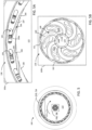
Figure 6A is a front perspective cut-away view of a portion of the hub manifold, showing an internal hub ductwork arrangement of the hub manifold; -
Figure 6B is a front perspective cut-away view of another portion of the hub manifold, showing another internal hub ductwork arrangement of the hub manifold; -
Figure 6C is a side view of an upper portion of the hub manifold; -
Figure 7A is a front perspective cut-away view of a portion of the shroud manifold, showing an internal shroud ductwork arrangement of the shroud manifold; -
Figure 7B is a front perspective cut-away view of another portion of the shroud manifold, showing another internal shroud ductwork arrangement of the shroud manifold; -
Figure 8 is an exploded view of portions of a hub manifold structure and a disc pack of the drive ofFigure 1 ; -
Figure 9A is a front perspective partial cut-away view of a portion of another hub manifold for a drive like that ofFigure 1 , showing portions of an internal hub ductwork arrangement of the hub manifold; -
Figure 9B is a front perspective partial cut-away view of another portion of hub manifold ofFigure 9A , showing portions of another internal hub ductwork arrangement of the hub manifold; -
Figure 10 is a simplified schematic representation of portions of another cohesion-type drive; -
Figure 11 is a simplified schematic representation of another hub manifold for a drive like that ofFigure 1 ; and -
Figure 12 includes charts and a table showing the difference in stress distribution for a hollow rotating disc with and without imposed radial loads at the inner and outer radiuses. - Various apparatuses or processes will be described below to provide an example of an embodiment of each invention. No embodiment described below limits any disclosed invention and any invention may cover processes or apparatuses that differ from those described below. The inventions are not limited to apparatuses or processes having all of the features of any one apparatus or process described below or to features common to multiple or all of the apparatuses described below. It is possible that an apparatus or process described below is not an embodiment of any invention. Any invention disclosed in an apparatus or process described below may be the subject matter of another protective instrument, for example, a continuing patent application, and the applicants, inventors or owners do not intend to abandon, disclaim or dedicate to the public any such invention by its disclosure in this document.
- A cohesion-type drive includes a casing, a shaft rotatably supported in the casing for rotation about a drive axis, and a disc pack coaxial with the shaft and fixed to rotate therewith. The disc pack includes a plurality of coaxial discs that are spaced axially apart from one another by disc spaces forming a plurality of working chambers. Typical disc packs include annular discs, but some designs can include conical discs, reverse flow discs, hybrid discs, etc.
- In pump or compressor applications, the shaft is driven to rotate the discs and a fluid is conducted into a radially inner portion of the chambers. The rotating discs impart work on the fluid and the fluid is urged radially outwardly. In turbine applications, a fluid is discharged into a radially outer portion of the chambers. The fluid imparts work on the discs to drive rotation of the shaft in the circumferential direction and flows through the chambers radially inwardly.
- In some examples, the disc spaces can include a plurality of first chambers and a plurality of second chambers alternating axially with the first chambers. The first and second chambers can be in fluid isolation of one another. A first fluid can be conducted into the first chambers and a second fluid different from the first fluid can be conducted into the second chambers.
- In some examples, the first chambers can comprise one of compression chambers and turbine chambers, and the second chambers can comprise the other one of compression chambers and turbine chambers. In such examples, the cohesion-type drive can operate as a regenerator in combination with a fluid power device. For example, the first chambers can comprise compression chambers and a first fluid can be conducted into a radially inner portion of the compression chambers for compression thereof. The second chambers can comprise turbine chambers and a second fluid can be discharged into a radially outer portion of the second chambers to impart work on the disc pack for urging rotation of the shaft. The work imparted on the disc pack by the second fluid can be greater than the work extracted from the disc pack by the first fluid, thereby generating a net work output. In such examples, the first fluid can include a relatively cool fluid, such as atmospheric air, and the second fluid can include a relatively hot fluid, such as combustion gases. This can facilitate regenerative heat exchange across the discs as the first and second fluids pass through respective chambers, and can help cool the discs.
- In some examples, after compression, the first fluid can be evacuated from the first chambers and conducted to a combustion chamber. The first fluid can be mixed with fuel and the mixture can be combusted to generate the combustion gases for discharging into the second chambers.
- Such cohesion-type drives as described above generally require manifolds to conduct working fluid into and/or out from the working chambers, and the manifold design can affect the performance of the drive. According to some aspects of the teachings disclosed herein, design improvements can advantageously be made to manifolds for such cohesion-type drives.
- Referring to
Figure 1 , an examplecohesion type drive 100 is illustrated. Thedrive 100 includes acasing 102 extending along adrive axis 104 between a casingfront end 106 and a casingrear end 108 spaced axially apart from thefront end 106 in an axially rearward direction. Ashaft 110 is rotatably supported in thecasing 102 for rotation about thedrive axis 104 in a circumferential first direction 112 (also referred to as forward direction 112). - Referring to
Figure 2 , in the example illustrated, adisc pack 114 is supported in thecasing 102 coaxial with theshaft 110 and is fixed to rotate therewith. Referring toFigure 2A , thedisc pack 114 includes a plurality of axially spaced apartdiscs 116. In the example illustrated, thediscs 116 are generally annular. - Referring to
Figure 3 , in the example illustrated, thediscs 116 are spaced axially apart from one another bydisc spaces 118. Thedisc spaces 118 define a plurality ofcompression chambers 120, and a plurality ofturbine chambers 122 alternating axially with and in fluid isolation of thecompression chambers 120. - Referring still to
Figure 3 , in the example illustrated, thedrive 100 further includes a first manifold 128 (also referred to ashub manifold 128 or bore manifold 128) in thecasing 102 radially inward of thedisc pack 114. Thehub manifold 128 includes a hub first ductwork 130 (also referred to as compression chamber inlet ductwork 130) for fluid communication with thecompression chambers 120. The compressionchamber inlet ductwork 130 is in fluid communication with thecompression chambers 120 for conducting a first fluid into thecompression chambers 120 to compress the first fluid during rotation of thedisc pack 114 in theforward direction 112. The first fluid can include, for example, air. - In the example illustrated, the
hub manifold 128 includes a hub second ductwork 132 (also referred to as turbine chamber outlet ductwork 132) for fluid communication with theturbine chambers 122. In the example illustrated, the turbinechamber outlet ductwork 132 is in fluid communication with theturbine chambers 122 for evacuating a second fluid from theturbine chambers 122. In the example illustrated, the second fluid has a temperature greater than the first fluid, and can include, for example, combustion gases. In the example illustrated, the compressionchamber inlet ductwork 130 and the turbinechamber outlet ductwork 132 are in fluid isolation of one another. - In the example illustrated, the
drive 100 further includes a second manifold 138 (also referred to as shroud manifold 138) in thecasing 102 radially outward of thedisc pack 114. In the example illustrated, theshroud manifold 138 includes a shroud first ductwork 140 (also referred to as a turbine chamber inlet ductwork 140) in fluid communication with theturbine chambers 122. The turbinechamber inlet ductwork 140 is in fluid communication with theturbine chambers 122 for conducting the second fluid into theturbine chambers 122 to urge rotation of thedisc pack 114 in theforward direction 112. In the example illustrated, theshroud manifold 138 further includes a shroud second ductwork 142 (also referred to as compression chamber outlet ductwork 142) in fluid communication with thecompression chambers 120. The compressionchamber outlet ductwork 142 is in fluid communication with thecompression chambers 120 for evacuating the first fluid from thecompression chambers 120. In the example illustrated, the turbinechamber inlet ductwork 140 and the compressionchamber outlet ductwork 142 are in fluid isolation of one another. - At least one of the hub manifold and the shroud manifold can be fixed to rotate with the shaft about the drive axis. In the example illustrated, the
hub manifold 128 is fixed to rotate with theshaft 110 about thedrive axis 104, and forms part of the rotor assembly of thedrive 100. Thehub manifold 128 includes ahub body 150 coaxial with the drive axis, and each of the compressionchamber inlet ductwork 130 and the turbinechamber outlet ductwork 132 are internal the hub body 150 (see alsoFigures 6A, 6B ). Providing the ductwork internal the manifold body can allow for optimization of the ductwork geometry to, for example, help condition fluid flow, minimize fluid losses, accommodate fluid flow fields at the manifold interfaces, control flow distribution among the working chambers, and control heat transfer between fluids passing through the ductwork. - In the example illustrated, the
hub body 150 is generally cylindrical. Thehub body 150 includes a hub bodyfirst endface 150a and a hub bodysecond endface 150b axially opposite the hub body first endface 150a. In the example illustrated, the hub bodyfirst endface 150a is located toward the casingfront end 106, and the hub bodysecond endface 150b is spaced apart from the hub body first endface 150a toward the casingrear end 108. - In the example illustrated, the
hub body 150 includes a hub bodyouter surface 152 directed radially outwardly toward thedisc pack 114 and extending axially between the hub body first and second endfaces 150a, 150b. In the example illustrated, thedisc spaces 118 are bounded radially by the hub bodyouter surface 152. Thehub body 150 includes a radially inwardly directed hub bodyinner surface 154 radially opposite the hub bodyouter surface 152 and extending axially between the hub body first and second endfaces 150a, 150b. In the example illustrated, thehub manifold 128 includes a hub manifold bore 156 in thehub body 150 coaxial with thedrive axis 104, and bounded radially by the hub bodyinner surface 154. - In the example illustrated, the compression
chamber inlet ductwork 130 includes a plurality of hub first ports 160 (also referred to as compression chamber inlet ports 160) open to the hub bodyouter surface 152 for discharging the first fluid from the compressionchamber inlet ductwork 130 into thecompression chambers 120. In the example illustrated, the turbinechamber outlet ductwork 132 includes a plurality of hub second ports 162 (also referred to as turbine chamber outlet ports 162) open to the hub bodyouter surface 152 for evacuating the second fluid from theturbine chambers 122 and into the turbinechamber outlet ductwork 132. - Referring to
Figure 6C , in the example illustrated, the compressionchamber inlet ports 160 are arranged in axially spaced apart hub first sets 160a (also referred to as hub inlet sets 160a), with eachset 160a of compressionchamber inlet ports 160 open to arespective compression chamber 120. In the example illustrated, the turbinechamber outlet ports 162 are arranged in axially spaced apart hub second sets 162a (also referred to as hub outlet sets 162a), with eachset 162a of turbinechamber outlet ports 162 open to arespective turbine chamber 122. In the example illustrated, the hub outlet sets 162a alternate axially with the hub inlet sets 160a. - Referring to
Figure 4B , in the example illustrated, the compressionchamber inlet ports 160 in eachset 160a are spaced circumferentially apart from one another about thedrive axis 104. In the example illustrated, the compressionchamber inlet ports 160 in eachset 160a lie in a common hubfirst plane 163a oriented normal to the drive axis 104 (see alsoFigure 6C ). Referring toFigure 5B , in the example illustrated, the turbinechamber outlet ports 162 in eachset 162a are spaced circumferentially apart from one another about thedrive axis 104. In the example illustrated, the turbinechamber outlet ports 162 in eachset 162a lie in a common hubsecond plane 163b normal to the drive axis 104 (see alsoFigure 6C ). - Referring to
Figure 4B , in the example illustrated, the compressionchamber inlet ductwork 130 includes a plurality of circumferentially spaced aparthub headers 164 in fluid communication with the compressionchamber inlet ports 160. Referring toFigure 3 , eachhub header 164 extends along a hub header centerline 165 between a hub headerfirst end 164a open to the hub bodyfirst endface 150a for receiving the first fluid, and a hub headersecond end 164b spaced axially apart from the hub headerfirst end 164a toward the hub bodysecond endface 150b (see alsoFigures 2B and4B ). - Referring to
Figure 4B , in the example illustrated, the header centerline 165 extends helically about thedrive axis 104 in the circumferentialforward direction 112 from the headerfirst end 164a to the headersecond end 164b. Referring toFigure 2B , eachheader 164 has a cross sectional area perpendicular to thedrive axis 104. In the example illustrated, the cross-sectional area of eachheader 164 decreases along the header centerline 165 from the headerfirst end 164a toward the headersecond end 164b. - Referring still to
Figure 2B , in the example illustrated, thehub manifold 128 includes a plurality of hub aerodynamic features 134 (see alsoFigure 8 ) extending at least partially across the header first ends 164a and fixed to rotate with thehub body 150 for conditioning flow of the first fluid entering the header first ends 164a. In the example illustrated, theaerodynamic features 134 comprisehub airfoils 136. In the example illustrated, thehub airfoils 136 are spaced circumferentially apart from one another about thedrive axis 104 and extend radially across respective header first ends 164a (see alsoFigure 8 ). - Referring to
Figure 3 , in the example illustrated, the compressionchamber inlet ductwork 130 includes a plurality of hub first conduits 166 (also referred to as hub inlet conduits 166) for conducting the first fluid from thehub headers 164 to the compressionchamber inlet ports 160. Referring toFigure 4B , eachhub inlet conduit 166 extends along a hubinlet conduit centerline 167 between a respective compressionchamber inlet port 160 and a hubfirst conduit end 166a (also referred to as a hub inletconduit intake end 166a) open to arespective hub header 164. - In the example illustrated, the hub
inlet conduit centerline 167 curves circumferentially between the compressionchamber inlet port 160 and the hubfirst conduit end 166a. In the example illustrated, theinlet conduit centerline 167 extends from the inletconduit intake end 166a to the compressionchamber inlet port 160 in a circumferential second direction (also referred to as a reverse direction) opposite theforward direction 112 for directing fluid passing radially outwardly through theinlet conduit 166 in the reverse direction. This can help provide an inflow velocity of the first fluid corresponding to the developed flow field in the radially inner portion of thecompression chambers 120, and may help improve compression efficiency. - Referring to
Figure 3 , in the example illustrated, a second-fluid evacuation space 170 is provided in thecasing 102 for receiving the second fluid discharged from thehub manifold 128, and evacuating the second fluid from thecasing 102. In the example illustrated, the second-fluid evacuation space 170 is provided in the hub manifold bore 156. - In the example illustrated, the turbine
chamber outlet ductwork 132 includes a plurality of hub second conduits 168 (also referred to as hub outlet conduits 168) for conducting the second fluid from the turbinechamber outlet ports 162 to the second-fluid evacuation space 170. Referring toFigure 5B , in the example illustrated, eachoutlet conduit 168 extends along a hub second conduit centerline 169 (also referred to as a hub outlet conduit centerline 169) between a respective turbinechamber outlet port 162 and a hub second conduit end 169a (also referred to as a hub outlet conduit discharge end 169a). The hub outlet conduit discharge end 169a is open to the hub body inner surface 154 (and the hub manifold bore 156, seeFigure 3 ) and is in fluid communication with theevacuation space 170. - In the example illustrated, the hub
outlet conduit centerline 169 curves circumferentially between the turbinechamber outlet port 162 and the hub second conduit end 169a. In the example illustrated, theoutlet conduit centerline 169 extends from the turbinechamber outlet port 162 to the outlet conduit discharge end 169a in the circumferentialforward direction 112 for directing the second fluid passing radially inwardly through thehub outlet conduit 168 in theforward direction 112. This can help provide an outlet curvature having an intake portion corresponding to the developed flow field in the radially inner portion of the turbine chambers. - Referring to
Figure 3 , the second fluid can be evacuated through the second-fluid evacuation space 170 in an axial direction. In the example illustrated, the second fluid is evacuated through theevacuation space 170 in the axially forward direction. - Referring still to
Figure 3 , in the example illustrated, theshaft 110 includes ashaft body 172 in the hub manifold bore 156, and ashaft bore 174 in theshaft body 172 coaxial with thedrive axis 104. In the example illustrated, the shaft bore 174 comprises the second-fluid evacuation space 170. In the example illustrated, theshaft 110 includes a plurality ofshaft ports 176 extending radially through theshaft body 172 and between respectivehub outlet conduits 168 and the second-fluid evacuation space 170 for conducting the second fluid from theoutlet conduits 168 to theevacuation space 170. - In the example illustrated, at least a portion of the
hub body 150 is formed of a thermally conductive material for conductively transferring heat between the first fluid passing through the compressionchamber inlet ductwork 130 and the second fluid passing through the turbinechamber outlet ductwork 132. - Referring to
Figure 2 , in the example illustrated, theshroud manifold 138 is fixed to rotate with theshaft 110 about thedrive axis 104, and forms part of the rotor assembly of thedrive 100. Referring toFigure 3 , theshroud manifold 138 includes ashroud body 180 coaxial with thedrive axis 104, and each of the turbinechamber inlet ductwork 140 and the compressionchamber outlet ductwork 142 is internal theshroud body 180. - In the example illustrated, the
shroud body 180 is generally cylindrical. Theshroud body 180 includes a shroud body first endface 180a, and a shroud bodysecond endface 180b axially opposite the shroud body first endface 180a (see alsoFigures 2A and2C ). In the example illustrated, the shroud bodyfirst endface 180a is located toward the casingrear end 108, and the shroud bodysecond endface 180b is spaced apart from the shroud body first endface 180a toward the casingfront end 106. - In the example illustrated, the
shroud body 180 includes a shroud bodyinner surface 184 directed radially inwardly toward thedisc pack 114 and extending axially between the first and second endfaces 180a, 180b. In the example illustrated, theshroud body 180 includes a radially outwardly directed shroud bodyouter surface 182 radially opposite the shroud bodyinner surface 184 and extending axially between the shroud body first and second endfaces 180a, 180b. In the example illustrated, theshroud manifold 138 includes a shroud manifold bore 186 in theshroud body 180 coaxial with thedrive axis 104, and bounded radially by the shroud bodyinner surface 184. The shroud manifold bore 186 is sized to receive thedisc pack 114 therein, and thedisc spaces 118 are bounded radially by the shroud bodyinner surface 184. - In the example illustrated, the turbine
chamber inlet ductwork 140 includes a plurality of shroud first ports 190 (also referred to as turbine chamber inlet ports 190) open to the shroud bodyinner surface 184 for discharging the second fluid from the turbinechamber inlet ductwork 140 and into theturbine chambers 122 to urge rotation of thedisc pack 114 in theforward direction 112. In the example illustrated, the compressionchamber outlet ductwork 142 includes a plurality of shroud second ports 192 (also referred to as compression chamber outlet ports 192) open to the bodyinner surface 184 for evacuating the first fluid from thecompression chambers 120 and into the compressionchamber outlet ductwork 142. - Referring to
Figure 2C , in the example illustrated, the plurality of turbinechamber inlet ports 190 are arranged in axially spaced apart shroud first sets 190a (also referred to as shroud inlet sets 190a), with eachset 190a of turbinechamber inlet ports 190 open to arespective turbine chamber 122. In the example illustrated, the plurality of compressionchamber outlet ports 192 are arranged in axially spaced apart shroud second sets 192a (also referred to as shroud outlet sets 192a), with each set of compressionchamber outlet ports 192 open to arespective compression chamber 120. In the example illustrated, the shroud inlet sets 190a alternate axially with the shroud outlet sets 192a. - Referring to
Figure 5A , in the example illustrated, the turbinechamber inlet ports 190 in eachset 190a are spaced circumferentially apart from one another about thedrive axis 104. In the example illustrated, the turbinechamber inlet ports 190 in eachset 190a lie in a common shroudfirst plane 193a oriented normal to thedrive axis 104. In the example illustrated, each shroudfirst plane 193a is coincident with a respective hubsecond plane 163b, and the turbinechamber inlet ports 190 open to arespective turbine chamber 122 are generally in axial alignment with the turbinechamber outlet ports 162 open to thatsame turbine chamber 122. - Referring to
Figure 4A , in the example illustrated, the compressionchamber outlet ports 192 in eachset 192a are spaced circumferentially apart from one another about thedrive axis 104. In the example illustrated, the compressionchamber outlet ports 192 in eachset 192a lie in a common shroudsecond plane 193b oriented normal to the drive axis. In the example illustrated, each shroudsecond plane 193b is coincident with a respective hubfirst plane 163a, and the compressionchamber outlet ports 192 open to arespective compression chamber 120 are generally in axial alignment with the compressionchamber inlet ports 160 open to thatsame compression chamber 120. - Referring to
Figure 3 , in the example illustrated, the turbinechamber inlet ductwork 140 includes a plurality of circumferentially spaced apartshroud headers 194 in fluid communication with the turbine chamber inlet ports 190 (see alsoFigure 5A ). Eachshroud header 194 extends along a shroud header centerline 195 between a shroud headerfirst end 194a open to the shroud body first endface 180a for receiving the second fluid and a shroud headersecond end 194b spaced axially apart from the shroud headerfirst end 194a toward the shroud bodysecond endface 180b. In the example illustrated, the shroud header centerline 195 extends generally parallel to thedrive axis 104. - Referring to
Figure 2C , in the example illustrated, theshroud manifold 138 includes a plurality of shroudaerodynamic features 144 extending at least partially across the shroud header first ends 194a and fixed to rotate with theshroud body 180 for conditioning flow of the second fluid entering theshroud headers 194. Referring toFigure 5A , in the example illustrated, the shroudaerodynamic features 144 compriseshroud airfoils 146. The shroud airfoils 146 are spaced circumferentially apart from one another about thedrive axis 104 and extend radially across respective shroud header first ends 194a. - Referring to
Figure 3 , in the example illustrated, the turbinechamber inlet ductwork 140 includes a plurality of shroud first conduits 196 (also referred to as shroud inlet conduits 196) for conducting the second fluid from theshroud headers 194 to the turbinechamber inlet ports 190. Referring toFigure 5A , eachshroud inlet conduit 196 extends along a shroud first conduit centerline 197 (also referred to as shroud inlet conduit centerline 197) between a respective turbinechamber inlet port 190 and a shroudfirst conduit end 196a (also referred to as a shroud inletconduit intake end 196a) open to arespective shroud header 194. - In the example illustrated, the shroud
inlet conduit centerline 197 curves circumferentially between the turbinechamber inlet port 190 and the shroud inletconduit intake end 196a. In the example illustrated, the shroudinlet conduit centerline 197 extends from the inletconduit intake end 196a to the turbinechamber inlet port 190 in the circumferentialforward direction 112 for directing fluid passing radially inwardly through theshroud inlet conduit 196 and into arespective turbine chamber 122 in theforward direction 112 to urge rotation of thedisc pack 114. - Referring to
Figure 3 , in the example illustrated, a first-fluid evacuation space 178 is provided in thecasing 102 for receiving the first fluid discharged from theshroud manifold 138, and evacuating the first fluid from thecasing 102. In the example illustrated, the first-fluid evacuation space 178 is radially intermediate theshroud manifold 138 and aninner surface 103 of thecasing 102. In the example illustrated, the first-fluid evacuation space 178 is bounded radially by the shroud bodyouter surface 182. The first fluid can be evacuated through the first-fluid evacuation space 178 in an axial direction. In the example illustrated, the second fluid is evacuated through theevacuation space 178 in the axially rearward direction. In some examples, the first-fluid evacuation space 178 can comprise a vaneless space open to a semi-vaneless space in the casing for facilitating diffusion of the first fluid. - Referring still to
Figure 3 , in the example illustrated, the compressionchamber outlet ductwork 142 includes a plurality of shroud second conduits 198 (also referred to as shroud outlet conduits 198) for conducting the first fluid from the compressionchamber outlet ports 192 to the first-fluid evacuation space 178. Referring toFigure 4A , eachoutlet conduit 198 extends along a shroudoutlet conduit centerline 199 between a respective compressionchamber outlet port 192 and a shroudsecond conduit end 198a (also referred to as a shroud outlet conduit dischargeend 198a) open to the shroud bodyouter surface 182 and in fluid communication with the first-fluid evacuation space 178. In the example illustrated, the shroudoutlet conduit centerline 199 curves circumferentially between thechamber outlet port 192 and the shroud outlet conduit dischargeend 198a. - In the example illustrated, the
shroud outlet conduit 198 includes anintake portion 200 extending along anintake portion centerline 201 from the compressionchamber outlet port 192 toward the outlet conduit dischargeend 198a. In the example illustrated, theintake portion centerline 201 curves circumferentially from the compressionchamber outlet port 192 toward the outlet conduit dischargeend 198a. In the example illustrated, theintake portion centerline 201 extends from the compressionchamber outlet port 192 toward the outlet conduit dischargeend 198a in the circumferential reverse direction (opposite the forward direction 112) for directing the first fluid entering and passing radially outwardly through theintake portion 200 in the reverse direction. This can help accommodate the developed flow field in the radially outer portion of the compression chambers. - In the example illustrated, the
shroud outlet conduit 198 includes adischarge portion 202 extending along adischarge portion centerline 203 from theintake portion 200 to the outlet conduit dischargeend 198a. In the example illustrated, thedischarge portion centerline 203 curves circumferentially from theintake portion 200 to the outlet conduit dischargeend 198a. Thedischarge centerline 203 and theintake portion centerline 201 can curve in circumferentially opposite directions. - In the example illustrated, the
discharge portion centerline 203 can extend from theintake portion 200 to the outlet conduit dischargeend 198a in one of the circumferentialforward direction 112 and the reverse direction for directing the first fluid passing radially outwardly through thedischarge portion 202 and into theevacuation space 178 in the one of theforward direction 112 and the reverse direction. In the example illustrated, thedischarge portion centerline 203 extends from theintake portion 200 to the outlet conduit dischargeend 198a in the circumferentialforward direction 112 for directing the first fluid passing radially outwardly through thedischarge portion 202 and into theevacuation space 178 in theforward direction 112. This can help machine performance. - The
drive 100 can include one or more disc mounting features. The disc mounting features can, for example, facilitate axial positioning of thediscs 116 and/or rotational locking of thedisc pack 114 with one or both of thehub manifold 128 and theshroud manifold 138. The disc mounting features can include, for example, weldments, keys, keyways, and/or spacers. In some examples, the disc pack can be bonded (e.g. welded or adhered) to one or both of the hub manifold body and the shroud manifold body to rotationally lock thedisc pack 114 thereto. - Referring to
Figure 2C , in the example illustrated, the disc mounting features include a plurality of axially spaced apartcircumferential shroud grooves 204 in the shroud bodyinner surface 184. Eachshroud groove 204 is axially intermediate a respective shroud inlet set 190a of turbinechamber inlet ports 190, and a respective axially adjacent shroud outlet set 192a of compressionchamber outlet ports 192. In the example illustrated, eachshroud groove 204 receives a radially outer peripheral edge of arespective disc 116 to facilitate axial positioning of thediscs 116. - Referring to
Figure 6C , in the example illustrated, the disc mounting feature further includes a plurality of axially spaced apart circumferential hub grooves 205 (shown schematically inFigure 6C -see alsogrooves 1205 inFigures 9A and 9B ) in the hub bodyouter surface 152. Eachhub groove 205 is axially intermediate a respective hub inlet set 160a of compressionchamber inlet ports 160 and a respective axially adjacent hub outlet set 162a of turbinechamber outlet ports 162. Eachhub groove 205 can receive a radially inner peripheral edge of arespective disc 116 to facilitate axial positioning of the discs. In the example illustrated, the shroud andhub grooves - The
discs 116 can be positioned into theshroud grooves 204 through, for example, thermal expansion of theshroud body 180 relative to thediscs 116 and/or thermal contraction of thediscs 116 relative to theshroud body 180. Thediscs 116 can be positioned into thehub grooves 205 through, for example, thermal contraction of thehub body 150 relative to thediscs 116 and/or thermal expansion of thediscs 116 relative to thehub body 150. - In some examples, the disc mounting feature includes an interference structure for engagement with the
disc pack 114 to rotationally lock thedisc pack 114 with one or both of thehub manifold 128 and theshroud manifold 138. The interference structure can comprise, for example, axially facing groove surfaces of theshroud grooves 204 and/or thehub grooves 205 for providing an interference fit with thediscs 116. In some examples, the interference structure can include, for example, protrusions, pins, and/or keys for engagement with corresponding recesses, apertures, and/or keyways in one ormore discs 116 to rotationally lock thedisc pack 114 with one or both of thehub manifold 128 and theshroud manifold 138. - Referring to
Figure 8 , in the example illustrated, thehub body 150 includes a core 206 coaxial with thedrive axis 104 and through which at least a portion of the compressionchamber inlet ductwork 130 and the turbine chamber outlet ductwork 132 passes. In the example illustrated, thehub headers 164,hub inlet conduits 166, andhub outlet conduits 168 pass through the core 206 (see alsoFigure 4B ). - Referring still to
Figure 8 , in the example illustrated, thecore 206 is of integral, unitary, one-piece construction. Thecore 206 can be formed using, for example, a 3D printing or casting process which can help provide for complex ductwork geometry internal thecore 206. In some cases, components formed using such processes may have limited structural integrity and/or material properties that may be less than ideal for rotary applications involving high rotational and/or thermal stresses. In the example illustrated, thehub body 150 includes aframe 208 mounted to thecore 206 for exerting an inwardly directed force on thecore 206 to regulate a stress distribution therein during operation (see alsoFigures 6A and 6B ). This can help improve, for example, the operating range and/or life expectancy of thecore 206. - Referring to
Figure 8 , in the example illustrated, thecore 206 has a radially outwardly directed coreouter surface 210, and theframe 208 includes anouter sleeve 212 mounted over thecore 206 and in engagement with the coreouter surface 210 for inducing radial compression of the core 206 during operation. In the example illustrated, theouter sleeve 212 comprises the hub bodyouter surface 152. In some examples, theouter sleeve 212 can induce radial compression through, for example, an interference fit with the coreouter surface 210, and/or through a clamping assembly. - In the example illustrated, the
frame 208 includes a plurality ofanchors 214. Eachanchor 214 extends between an anchorouter end 214a fixed to theouter sleeve 212 and an anchorinner end 214b fixed to theshaft 110 for inducing radial compression of thecore 206. In the example illustrated, thehub body 150 includes a plurality ofapertures 216 passing radially through thecore 206, and theanchors 214 extend throughrespective apertures 216. This can facilitate alignment between the ductwork portions passing through theouter sleeve 212 and the ductwork portions internal thecore 206, and between theshaft ports 176 and the ductwork portions internal thecore 206. - Referring to
Figures 2B and2D , in the example illustrated, thecore 206 has a corefirst endface 206a and a core second endface 206b axially opposite the corefirst endface 206a. Theframe 208 includes afirst end cap 218a in engagement with the corefirst endface 206a, and asecond end cap 218b in engagement with the core second endface 206b. The first andsecond end caps second end caps outer sleeve 212. - Referring to
Figure 2D , in the example illustrated, each of the first andsecond endcaps outer endcap portion 220 fixed to theouter sleeve 212 and thedisc pack 114, a radiallyinner endcap portion 222 fixed to theshaft 110, and a radiallyintermediate endcap portion 224 connecting the radiallyouter endcap portion 220 and the radiallyinner endcap portion 222. - In the example illustrated, torque load between the
disc pack 114 and theshaft 110 is transferred through theframe 208. This can help reduce torque load transfer through thecore 206, which may help improve the operating range and/or life expectancy of thecore 206. In the example illustrated, theframe 208 includes a discpack mounting portion 226 for engagement with thedisc pack 114 to fix the disc pack to thehub body 150. The discpack mounting portion 226 can include theouter sleeve 212, and/or the radiallyouter endcap portions 220. - In the example illustrated, the
frame 208 includes ashaft mounting portion 228 for engagement with theshaft 110 to fix theshaft 110 to theframe 208. Theshaft mounting portion 228 is spaced radially inwardly apart from the discpack mounting portion 226. In the example illustrated, theshaft mounting portion 228 includes the radiallyinner endcap portions 222. - In the example illustrated, the
frame 208 includes one or more torque-transfer members 230 for transferring torque between the discpack mounting portion 226 and theshaft mounting portion 228. Referring toFigure 2D , each torque-transfer member 230 has a radiallyouter end 230a fixed to the discpack mounting portion 226 and a radiallyinner end 230b fixed to theshaft mounting portion 228. In the example illustrated, the torque-transfer members 230 include the radiallyintermediate endcap portions 224. - Referring to
Figure 8 , in the example illustrated, hubaerodynamic features 134 are mounted to theframe 208. - Referring to
Figures 9A-9B , an example of anotherhub manifold 1128 for a rotor assembly of a cohesion-type drive is illustrated. The manifold 1128 has similarities to thehub manifold 128, and like features are identified by like reference characters, incremented by 1000. - In the example illustrated, the
manifold 1128 includes amanifold body 1150 extending along adrive axis 1104 for rotation thereabout. Thebody 1150 includes afirst endface 1150a, a second endface axially opposite thefirst endface 1150a, and a radially outwardly directed bodyouter surface 1152 extending between the first and second endfaces 1150a, 1150b. In the example illustrated, the body is of integral, unitary, one-piece construction. In the example illustrated, the hub manifold includes a plurality ofgrooves 1205 in the bodyouter surface 1152 for receiving radially inner peripheral edges of discs of the drive to facilitate mounting of the discs. - Referring to
Figure 10 , another example of a cohesion-type drive 2100 is illustrated schematically. The cohesion-type drive 2100 has similarities to thedrive 100, and like features are identified by like reference characters, incremented by 2000. In the example illustrated, thedrive 2100 includes a hub manifold 2128 having a manifold body 2150 extending along a drive axis 2104 for rotation thereabout. The body 2150 includes afirst endface 2150a, asecond endface 2150b axially opposite thefirst endface 2150a, a radially outwardly directed outer surface 2152 extending between the first and second endfaces 2150a, 2150b, and a radially inwardly directlyinner surface 2154 radially opposite the outer surface 2152. - In the example illustrated, the body 2150 is tapered radially along the drive axis 2104. This can allow for a variation in an inner radius of the first and second working
chambers outer radius 2232. In the example illustrated, the bodyouter radius 2232 decreases along the drive axis 2104 from the first endface 2150a toward thesecond endface 2150b of the body 2150. In the example illustrated, theinner surface 2154 is spaced radially apart from the drive axis 2104 by a bodyinner radius 2234. In the example illustrated, the bodyinner radius 2234 decreases along the drive axis 2104 from the first endface 2150a toward thesecond endface 2150b of the body 2150. - Referring to
Figure 11 , an example of anothermanifold 3128 for a rotor assembly of a cohesion-type drive is illustrated schematically. The manifold 3128 has similarities to thehub manifold 128, and like feature are identified by like reference characters, incremented by 3000. - In the example illustrated, the
manifold 3128 includes amanifold body 3150 extending along adrive axis 3104 for rotation thereabout. Thebody 3150 includes acore 3206 coaxial with thedrive axis 3104, and aframe 3208 mounted to thecore 3206 for exerting an inwardly directed force on thecore 3206 to regulate a stress distribution therein during operation of the drive. Themanifold body 3150 includes ductwork internal thebody 3150 for fluid communication with a plurality of working chambers of the drive. At least a portion of the ductwork passes through thecore 3206. - In the example illustrated, the
core 3206 has a radially outwardly directed core outer surface 3210, and theframe 3208 includes anouter sleeve 3212 mounted over thecore 3206 and in engagement with the core outer surface 3210 for inducing radial compression of thecore 3206 during operation. - In the example illustrated, the
body 3150 includes acore bore 3238 in thecore 3206 coaxial with thedrive axis 3104 and bounded by a radially inwardly directed coreinner surface 3239 of thecore 3206. In the example illustrated, theframe 3208 includes aninner sleeve 3240 in thecore bore 3238 and in engagement with the coreinner surface 3239. In the example illustrated, the outer andinner sleeves core 3206 during operation. In the example illustrated, theouter sleeve 3212 comprises a bodyouter surface 3152 of themanifold body 3150, and theinner sleeve 3240 comprises a bodyinner surface 3154 of themanifold body 3150. - In the example illustrated, the
frame 3208 includes a plurality ofanchors 3214 anchoring the outer andinner sleeves anchor 3214 extends between an anchorouter end 3214a fixed to theouter sleeve 3212 and an anchor inner end 3214b fixed to theinner sleeve 3240. In the example illustrated, the anchorouter ends 3214a are axially offset from the anchor inner ends 3214b. In the example illustrated, themanifold body 3150 includes a plurality of apertures passing radially through thecore 3206 between the core outer andinner surfaces 3210, 3239, and the anchors extend through respective apertures. - In the example illustrated, the
core 3206 has a corefirst endface 3206a and a coresecond endface 3206b axially opposite the corefirst endface 3206a. In the example illustrated, theframe 3208 includes a first end cap 3218a in engagement with the corefirst endface 3206a and asecond end cap 3218b in engagement with the coresecond endface 3206b. The first andsecond end caps 3218a, 3218b are anchored to one another for inducing axial compression of thecore 3206 during operation. In the example illustrated, the first andsecond end caps 3218a, 3218b are anchored to one another via the outer andinner sleeves - In the example illustrated, torque load between a disc pack 3114 and a
shaft 3110 is transferred through theframe 3208. In the example illustrated, theframe 3208 includes a discpack mounting portion 3226 for engagement with the disc pack 3114 to fix the disc pack to theframe 3208. The discpack mounting portion 3226 can include theouter sleeve 3212, and/or radially outer endcap portions. - In the example illustrated, the
frame 3208 includes a shaft mounting portion 3228 for engagement with theshaft 3110 to fix theshaft 3110 to theframe 3208. The shaft mounting portion 3228 is spaced radially inwardly from the discpack mounting portion 3226. The shaft mounting portion 3228 can include theinner sleeve 3240 and/or radially inner endcap portions. - In the example illustrated, the
frame 3208 includes one or more torque-transfer members 3230 for transferring torque between the discpack mounting portion 3226 and the shaft mounting portion 3228. Each torque-transfer member 3230 has a radiallyouter end 3230a fixed to the discpack mounting portion 3226 and a radiallyinner end 3230b fixed to the shaft mounting portion 3228. In the example illustrated, the torque-transfer members 3230 include radially intermediate endcap portions 3224. - Referring to
Figure 12 , charts A-D show the difference in stress distribution for a hollow rotating disc with and without imposed radial loads at the inner and outer radiuses. The charts A-D show radial, hoop, and shear stress distribution in the rotating disc for the four different boundary conditions outlined in Table 1 ofFigure 12 . The stresses are radial and normalized by a factor of (ρω 2)/8, with a positive stress indicating a tensile load. Radial and hoop stresses are shown in solid lines, and shear stress is shown in dashed lines. - These charts demonstrate how pre-stressing a hollow rotating disc, such as, for example, the
core 3206, may help reduce maximum shear stress under loading. This may improve the range of operation or life expectancy such components, and may also allow for control of the stress distribution throughout through variation in the boundary conditions, which may be helpful in cases where the components are of limited structural integrity. - The following aspects are part of the invention disclosed herein and are to be understood as standalone disclosure as well as in combination with features, modifications and embodiments described in the description so far
-
- 1) A cohesion-type drive, comprising:
- a) a casing;
- b) a shaft rotatably supported in the casing for rotation about a drive axis in a circumferential forward direction;
- c) a disc pack supported in the casing coaxial with the shaft and fixed to rotate therewith, the disc pack including a plurality of discs spaced axially apart from one another by disc spaces, the disc spaces comprising a plurality of compression chambers and a plurality of turbine chambers, the turbine chambers alternating axially with and in fluid isolation of the compression chambers;
- d) a hub manifold in the casing radially inward of the disc pack and fixed to rotate with the shaft about the drive axis, the hub manifold including: a hub body coaxial with the drive axis, a compression chamber inlet ductwork internal the hub body and in fluid communication with the compression chambers for conducting a first fluid into the compression chambers to compress the first fluid during rotation of the disc pack in the forward direction, and a turbine chamber outlet ductwork internal the hub body and in fluid communication with the turbine chambers for evacuating a second fluid from the turbine chambers, the turbine chamber outlet ductwork in fluid isolation of the compression chamber inlet ductwork; and
- e) a shroud manifold in the casing radially outward of the disc pack, the shroud manifold including a compression chamber outlet ductwork in fluid communication with the compression chambers for evacuating the first fluid from the compression chambers, and a turbine chamber inlet ductwork in fluid communication with the turbine chambers for conducting the second fluid into the turbine chambers to urge rotation of the disc pack in the forward direction, the turbine chamber inlet ductwork in fluid isolation of the compression chamber outlet ductwork.
- 2) The drive of aspect 1), wherein the hub body includes a body first endface, a body second endface axially opposite the body first endface, and a body outer surface extending between the body first and second endfaces and directed radially outwardly toward the disc pack, the disc spaces bounded radially by the body outer surface, and wherein the compression chamber inlet ductwork includes a plurality of compression chamber inlet ports open to the body outer surface for discharging the first fluid from the compression chamber inlet ductwork into the compression chambers, and the turbine chamber outlet ductwork includes a plurality of turbine chamber outlet ports open to the body outer surface for evacuating the second fluid from the turbine chambers and into the turbine chamber outlet ductwork.
- 3) The drive of aspect 2), wherein the compression chamber inlet ductwork includes a plurality of circumferentially spaced apart headers in fluid communication with the compression chamber inlet ports, each header extending along a header centerline between a header first end open to the body first endface for receiving the first fluid and a header second end spaced axially apart from the header first end toward the body second endface.
- 4) The drive of aspect 3), wherein the header centerline extends helically about the drive axis in the circumferential forward direction from the header first end to the header second end.
- 5) The drive of any one of aspects 3) to 4), wherein each header has a cross sectional area perpendicular to the drive axis, the cross-sectional area of each header decreasing along the header centerline from the header first end toward the header second end.
- 6) The drive of any one of aspects 3) to 5), wherein the hub manifold includes a plurality of aerodynamic features extending at least partially across the header first ends and fixed to rotate with the hub body for conditioning flow of the first fluid entering the header first ends.
- 7) The drive of any one of aspects 3) to 6), wherein the compression chamber inlet ductwork includes a plurality of inlet conduits for conducting the first fluid from the headers to the compression chamber inlet ports, each inlet conduit extending along an inlet conduit centerline between a respective compression chamber inlet port and an inlet conduit intake end open to a respective header.
- 8) The drive of aspect 7), wherein the inlet conduit centerline curves circumferentially between the compression chamber inlet port and the inlet conduit intake end.
- 9) The drive of any one of aspects 2) to 8), wherein the hub body includes a body inner surface radially opposite the body outer surface, and a manifold bore coaxial with the drive axis and bounded radially by the body inner surface, and wherein the turbine chamber outlet ductwork includes a plurality of outlet conduits for conducting the second fluid from the turbine chamber outlet ports to a fluid evacuation space provided in the manifold bore, each outlet conduit extending along an outlet conduit centerline between a respective turbine chamber outlet port and an outlet conduit discharge end open to the body inner surface and in fluid communication with the evacuation space.
- 10) The drive of aspect 9), wherein the outlet conduit centerline curves circumferentially between the turbine chamber outlet port and the outlet conduit discharge end.
- 11) The drive of any one of aspects 2) to 10), wherein the plurality of compression chamber inlet ports are arranged in axially spaced apart inlet sets, the compression chamber inlet ports in each set spaced circumferentially apart from one another about the drive axis and open to a respective compression chamber, and wherein the plurality of turbine chamber outlet ports are arranged in axially spaced apart outlet sets alternating axially with the inlet sets, the turbine chamber outlet ports in each set spaced circumferentially apart from one another about the drive axis and open to a respective turbine chamber.
- 12) The drive of any one of aspects 1) to 11), wherein the hub body includes a core coaxial with the drive axis and through which at least a portion of the compression chamber inlet ductwork and the turbine chamber outlet ductwork passes, and a frame mounted to the core for exerting an inwardly directed force on the core to regulate a stress distribution therein during operation.
- 13) The drive of aspect 12), wherein the core has a radially outwardly directed core outer surface, and the frame includes an outer sleeve mounted over the core and in engagement with the core outer surface for inducing radial compression of the core during operation.
- 14) The drive of any one of aspects 1) to 13), wherein the shroud manifold is fixed to rotate with the shaft about the drive axis, and includes a shroud body coaxial with the drive axis, the turbine chamber inlet ductwork and the compression chamber outlet ductwork internal the shroud body.
- 15) A cohesion-type drive, comprising:
- a) a casing;
- b) a shaft rotatably supported in the casing for rotation about a drive axis in a circumferential forward direction;
- c) a disc pack supported in the casing coaxial with the shaft and fixed to rotate therewith, the disc pack including a plurality of discs spaced axially apart from one another by disc spaces, the disc spaces comprising a plurality of compression chambers and a plurality of turbine chambers, the turbine chambers alternating axially with and in fluid isolation of the compression chambers;
- d) a hub manifold in the casing radially inward of the disc pack, the hub manifold including a compression chamber inlet ductwork in fluid communication with the compression chambers for conducting a first fluid into the compression chambers to compress the first fluid during rotation of the disc pack in the forward direction, and a turbine chamber outlet ductwork in fluid communication with the turbine chambers for evacuating a second fluid from the turbine chambers, the turbine chamber outlet ductwork in fluid isolation of the compression chamber inlet ductwork; and
- e) a shroud manifold in the casing radially outward of the disc pack and fixed to rotate with the shaft about the drive axis, the shroud manifold including: a shroud body coaxial with the drive axis, a compression chamber outlet ductwork internal the shroud body and in fluid communication with the compression chambers for evacuating the first fluid from the compression chambers, and a turbine chamber inlet ductwork internal the shroud body and in fluid communication with the turbine chambers for conducting the second fluid into the turbine chambers to urge rotation of the disc pack in the forward direction, the turbine chamber inlet ductwork in fluid isolation of the compression chamber outlet ductwork.
- 16) The drive of aspect 15), wherein the shroud body includes a body first endface, a body second endface axially opposite the body first endface, and a body inner surface extending between the first and second endfaces and directed radially inwardly toward the disc pack, the disc spaces bounded radially by the body inner surface, and wherein the compression chamber outlet ductwork includes a plurality of compression chamber outlet ports open to the body inner surface for evacuating the first fluid from the compression chambers and into the compression chamber inlet ductwork, and the turbine chamber inlet ductwork includes a plurality of turbine chamber inlet ports open to the body inner surface for discharging the second fluid from the turbine chamber outlet ductwork and into the turbine chambers to urge rotation of the disc pack in the forward direction.
- 17) The drive of aspect 16), wherein the turbine chamber inlet ductwork includes a plurality of circumferentially spaced apart headers in fluid communication with the turbine chamber inlet ports, each header extending between a header first end open to the body first endface for receiving the second fluid and a header second end spaced axially apart from the header first end toward the body second endface.
- 18) The drive of aspect 17), wherein the shroud manifold includes a plurality of aerodynamic features extending at least partially across the header first ends and fixed to rotate with the shroud body for conditioning flow of the second fluid entering the headers.
- 19) The drive of any one of aspects 17) to 18), wherein the turbine chamber inlet ductwork includes a plurality of inlet conduits for conducting the second fluid from the headers to the turbine chamber inlet ports, each inlet conduit extending along an inlet conduit centerline between a respective turbine chamber inlet port and an inlet conduit intake end open to a respective header.
- 20) The drive of aspect 19), wherein the inlet conduit centerline curves circumferentially between the turbine chamber inlet port and the inlet conduit intake end.
- 21) The drive of any one of aspects 19) to 20), wherein the shroud body has a body outer surface radially opposite the body inner surface, and the drive includes a fluid evacuation space in the casing radially intermediate the shroud manifold and an inner surface of the casing and bounded radially by the body outer surface for evacuating the first fluid, and wherein the compression chamber outlet ductwork includes a plurality of outlet conduits for conducting the first fluid from the compression chamber outlet ports to the evacuation space, each outlet conduit extending along an outlet conduit centerline between a respective compression chamber outlet port and an outlet conduit discharge end open to the body outer surface and in fluid communication with the evacuation space.
- 22) The drive of aspect 21), wherein the outlet conduit centerline curves circumferentially between the compression chamber outlet port and the outlet conduit discharge end.
- 23) The drive of any one of aspects 16) to 22), wherein the plurality of turbine chamber inlet ports are arranged in axially spaced apart inlet sets, the turbine chamber inlet ports in each set spaced circumferentially apart from one another about the drive axis and open to a respective turbine chamber, and wherein the plurality of compression chamber outlet ports are arranged in axially spaced apart outlet sets alternating axially with the inlet sets, the compression chamber outlet ports in each set spaced circumferentially apart from one another about the drive axis and open to a respective compression chamber.
- 24) A manifold for a rotor assembly of a cohesion-type drive, the manifold comprising:
- a) a manifold body extending along a drive axis for rotation thereabout in a circumferential first direction, the body including a first endface, a second endface axially opposite the first endface, a radially outwardly directed body outer surface extending between the first and second endfaces, a radially inwardly directed body inner surface radially opposite the body outer surface and extending between the first and second endfaces, and a manifold bore in the body coaxial with the drive axis and bounded radially by the body inner surface;
- b) a first ductwork internal the body for fluid communication with a plurality of first chambers of the drive, the first ductwork including a plurality of first ports open to one of the body inner surface and the body outer surface for conducting fluid between the first ductwork and the first chambers, the first ports arranged in a plurality of axially spaced apart first sets, each first set arranged for fluid communication with a respective first chamber; and
- c) a second ductwork internal the body for fluid communication with a plurality of second chambers of the drive, the second ductwork in fluid isolation of the first ductwork and including a plurality of second ports open to the one of the body inner surface and the body outer surface for conducting fluid between the second ductwork and the second chambers, the second ports arranged in a plurality of axially spaced apart second sets, the second sets alternating axially with the first sets, and each second set arranged for fluid communication with a respective second chamber.
- 25) The manifold of aspect 24), wherein the first ports in each set are spaced circumferentially apart from one another about the drive axis, and the second ports in each set are spaced circumferentially apart from one another about the drive axis.
- 26) The manifold of aspect 25), wherein the first ports in each set lie in a common first plane oriented normal to the drive axis, and the second ports in each set lie in a common second plane oriented normal to the drive axis.
- 27) The manifold of any one of aspects 24) to 26), wherein the first ductwork includes a plurality of circumferentially spaced apart headers in fluid communication with the first ports, each header extending along a header centerline between a header first end open to the body first endface for receiving fluid and a header second end spaced axially apart from the header first end toward the body second endface.
- 28) The manifold of aspect 27), wherein the header centerline extends helically about the drive axis in the circumferential first direction from the header first end to the header second end.
- 29) The manifold of any one of aspects 27) to 28), wherein each header has a cross sectional area perpendicular to the drive axis, the cross-sectional area of each header decreasing along the header centerline from the header first end toward the header second end.
- 30) The manifold of any one of aspects 27) to 29), further comprising a plurality of aerodynamic features extending at least partially across the header first ends and fixed to rotate with the body for conditioning flow of fluid entering the header first ends.
- 31) The manifold of any one of aspects 27) to 30), wherein the first ductwork includes a plurality of first conduits for conducting fluid between the headers and the first ports, each first conduit extending along a first conduit centerline between a respective first port and a first conduit end open to a respective header.
- 32) The manifold of aspect 31), wherein the first conduit centerline curves circumferentially between the first port and the first conduit end.
- 33) The manifold of any one of aspects 24) to 32), wherein the second ductwork includes a plurality of second conduits, each second conduit extending along a second conduit centerline between a respective second port and a second conduit end open to the other one of the body inner surface and the body outer surface.
- 34) The manifold of aspect 33), wherein the second conduit centerline curves circumferentially between the second port and the second conduit end.
- 35) The manifold of any one of aspects 24) to 34), wherein the manifold includes a plurality of axially spaced apart circumferential grooves in the one of the body inner surface and the body outer surface for mounting a plurality of discs of the drive, each groove axially intermediate a respective first set of first ports and a respective axially adjacent second set of second ports, and each groove configured for receiving a peripheral edge of a respective disc.
- 36) The manifold of aspect 35), wherein each groove includes an interference structure for engagement with a disc pack to rotationally lock the disc pack with the manifold.
- 37) The manifold of any one of aspects 24) to 36), wherein the body outer surface is spaced radially apart from the drive axis by a radius, the radius decreasing along the drive axis from the body first endface to the body second endface.
- 38) The manifold of any one of aspects 24) to 37), wherein the body includes a core coaxial with the drive axis and through which at least a portion of the first ductwork and the second ductwork passes, and a frame mounted to the core for exerting an inwardly directed force on the core to regulate a stress distribution therein during operation.
- 39) The manifold of aspect 38), wherein the core has a radially outwardly directed core outer surface, and the frame includes an outer sleeve mounted over the core and in engagement with the core outer surface for inducing radial compression of the core during operation.
- 40) A manifold for a rotor assembly of a cohesion-type drive, the manifold comprising:
- a) a manifold body extending along a drive axis for rotation thereabout, the body including a core coaxial with the drive axis, and a frame mounted to the core for exerting an inwardly directed force on the core to regulate a stress distribution therein during operation of the drive; and
- b) a first ductwork internal the body for fluid communication with a plurality of working chambers of the drive, at least a portion of the ductwork passing through the core.
- 41) The manifold of aspect 40), wherein the core has a radially outwardly directed core outer surface, and the frame includes an outer sleeve mounted over the core and in engagement with the core outer surface for inducing radial compression of the core during operation.
- 42) The manifold of aspect 41), wherein the body includes a core bore in the core coaxial with the drive axis and bounded by a radially inwardly directed core inner surface of the core, and the frame includes an inner sleeve in the core bore and in engagement with the core inner surface, the inner and outer sleeves anchored to one another for inducing radial compression of the core during operation.
- 43) The manifold of aspect 42), wherein the frame includes a plurality of anchors anchoring the inner and outer sleeves to one another, each anchor extending between an anchor outer end fixed to the outer sleeve and an anchor inner end fixed to the inner sleeve.
- 44) The manifold of aspect 43), wherein the manifold body includes a plurality of apertures passing radially through the core between the core inner and outer surfaces, and the anchors extend through respective apertures.
- 45) The manifold of any one of aspects 40) to 44), wherein the core has a core first endface and a core second endface axially opposite the core first endface, and the frame includes a first end cap in engagement with the core first endface and a second end cap in engagement with the core second endface, the first and second end caps anchored to one another for inducing axial compression of the core during operation.
- 46) The manifold of any one of aspects 40) to 45), wherein the frame includes a disc pack mounting portion for engagement with a disc pack of the drive to fix the disc pack to the frame, a shaft mounting portion spaced radially inwardly from the disc pack mounting portion for engagement with a shaft of the drive to fix the shaft to the frame, and one or more torque-transfer members for transferring torque between the disc pack mounting portion and the shaft mounting portion, each torque-transfer member having a radially outer end fixed to the disc pack mounting portion and a radially inner end fixed to the shaft mounting portion.
Claims (15)
- A rotary hub manifold for a cohesion-type drive, comprising:a) a manifold body extending along a drive axis for rotation thereabout, the body including a first endface, a second endface axially opposite the first endface, a radially outer surface extending between the first and second endfaces, and a radially inner surface opposite the radially outer surface and extending between the first and second endfaces, the radially inner surface defining a manifold bore in the body coaxial with the drive axis;b) a first ductwork internal the body for fluid communication with a plurality of first chambers of the cohesion-type drive, the first ductwork including a plurality of first ports open to the radially outer surface, for conducting a first fluid between the first ductwork and the plurality of first chambers, the first ports arranged in a plurality of axially spaced apart first sets, each first set arranged for fluid communication with a respective first chamber of the plurality of first chambers; andc) a second ductwork internal the body for fluid communication with a plurality of second chambers of the cohesion-type drive, the second ductwork in fluid isolation of the first ductwork and including a plurality of second ports open to the radially outer surface, for conducting a second fluid between the second ductwork and the plurality of second chambers, the plurality of second ports arranged in a plurality of axially spaced apart second sets, the second sets alternating axially with the first sets, and each second set arranged for fluid communication with a respective second chamber of the plurality of second chambers.
- The rotary hub manifold of claim 1, wherein the first ports in each first set are spaced circumferentially apart from one another about the drive axis, and the second ports in each second set are spaced circumferentially apart from one another about the drive axis, and optionally, wherein the first ports in each first set lie in a common first plane oriented normal to the drive axis, and the second ports in each second set lie in a common second plane oriented normal to the drive axis.
- The rotary hub manifold of any one of claims 1 to 2, wherein the first ductwork includes a plurality of circumferentially spaced apart headers in fluid communication with the first ports, each header extending along a header centerline between a header first end open to the body first endface for receiving the first fluid and a header second end spaced axially apart from the header first end toward the body second endface, and optionally, wherein each header centerline extends helically about the drive axis, and optionally, wherein each header has a cross sectional area perpendicular to the drive axis, the crosssectional area of each header tapering along the respective header centerline toward the respective header second end.
- The rotary hub manifold of any one of claims 1 to 3, further comprising a plurality of aerodynamic surfaces, each aerodynamic surface fixed relative to the manifold body, extending at least partially across a respective header first end of the plurality of header first ends, and shaped to condition flow of the first fluid entering the respective header first end, and optionally, wherein each aerodynamic surface comprises an airfoil.
- The rotary hub manifold of any one of claims 3 to 4, wherein the first ductwork includes a plurality of first conduits for conducting the first fluid between the headers and the first ports, each first conduit extending along a first conduit centerline between a respective first port of the plurality of first ports and a first conduit end open to a respective header of the plurality of headers, and optionally, wherein each first conduit centerline curves circumferentially.
- The rotary hub manifold of any one of claims 1 to 5, wherein the second ductwork includes a plurality of second conduits, each second conduit extending along a second conduit centerline between a respective second port of the plurality of second ports and a second conduit end open to of the manifold body, and optionally, wherein each second conduit centerline curves circumferentially, and optionally, wherein each second conduit end is open to a fluid evacuation space extending along the drive axis concentric with the manifold body.
- The rotary hub manifold of any one of claims 1 to 6, further comprising a plurality of axially spaced apart circumferential grooves in the radially outer surface for mounting a plurality of discs of the drive, each groove axially intermediate a respective first set of first ports of the plurality of first ports and a respective axially adjacent second set of second ports of the plurality of second ports, and each groove configured for receiving a peripheral edge of a respective disc of the plurality of discs.
- The rotary hub manifold of any one of claims 1 to 7, wherein the radially outer surface is spaced radially apart from the drive axis by a radius, the radius tapering along the drive axis toward the body second endface.
- The rotary hub manifold of any one of claims 1 to 8, wherein the body includes a core coaxial with the drive axis, and a frame mounted to the core for exerting an inwardly directed force on the core to regulate a stress distribution within the core during operation, and wherein at least a portion of the first ductwork and at least a portion of the second ductwork passes through the core.
- A rotary shroud manifold for a cohesion-type drive, comprising:a) a manifold body extending along a drive axis for rotation thereabout, the body including a first endface, a second endface axially opposite the first endface, a radially outer surface extending between the first and second endfaces, and a radially inner surface opposite the radially outer surface and extending between the first and second endfaces, the radially inner surface defining a manifold bore in the body coaxial with the drive axis;b) a first ductwork internal the body for fluid communication with a plurality of first chambers of the cohesion-type drive, the first ductwork including a plurality of first ports open to the radially inner surface, for conducting a first fluid between the first ductwork and the plurality of first chambers, the first ports arranged in a plurality of axially spaced apart first sets, each first set arranged for fluid communication with a respective first chamber of the plurality of first chambers; andc) a second ductwork internal the body for fluid communication with a plurality of second chambers of the cohesion-type drive, the second ductwork in fluid isolation of the first ductwork and including a plurality of second ports open to the radially inner surface, for conducting a second fluid between the second ductwork and the plurality of second chambers, the plurality of second ports arranged in a plurality of axially spaced apart second sets, the second sets alternating axially with the first sets, and each second set arranged for fluid communication with a respective second chamber of the plurality of second chambers.
- The rotary shroud manifold of claim 10, wherein the first ports in each first set are spaced circumferentially apart from one another about the drive axis, and the second ports in each second set are spaced circumferentially apart from one another about the drive axis, and optionally, wherein the first ports in each first set lie in a common first plane oriented normal to the drive axis, and the second ports in each second set lie in a common second plane oriented normal to the drive axis.
- The rotary shroud manifold of any one of claims 10 to 11, wherein the first ductwork includes a plurality of circumferentially spaced apart headers in fluid communication with the first ports, each header extending along a header centerline between a header first end open to the body first endface for receiving the first fluid and a header second end spaced axially apart from the header first end toward the body second endface, and optionally, wherein each header centerline extends parallel with the drive axis, and optionally, wherein the manifold further comprises a plurality of aerodynamic surfaces, each aerodynamic surface fixed relative to the manifold body, extending at least partially across a respective header first end of the plurality of header first ends, and shaped to condition flow of the first fluid entering the respective header first end, and optionally, wherein each aerodynamic surface comprises an airfoil.
- The rotary shroud manifold of claim 12, wherein the first ductwork includes a plurality of first conduits for conducting the first fluid between the headers and the first ports, each first conduit extending along a first conduit centerline between a respective first port of the plurality of first ports and a first conduit end open to a respective header of the plurality of headers, and optionally, wherein each first conduit centerline curves circumferentially.
- The rotary shroud manifold of any one of claims 10 to 13, wherein the second ductwork includes a plurality of second conduits, each second conduit extending along a second conduit centerline between a respective second port of the plurality of second ports and a second conduit end open to the radially outer surface of the manifold body, and optionally, wherein each second conduit centerline curves circumferentially, and optionally, wherein each second conduit end is open to a fluid evacuation space extending along the drive axis concentric with the manifold body.
- The rotary shroud manifold of any one of claims 10 to 14, further comprising a plurality of axially spaced apart circumferential grooves in the radially inner surface for mounting a plurality of discs of the drive, each groove axially intermediate a respective first set of first ports of the plurality of first ports and a respective axially adjacent second set of second ports of the plurality of second ports, and each groove configured for receiving a peripheral edge of a respective disc of the plurality of discs.
Applications Claiming Priority (4)
| Application Number | Priority Date | Filing Date | Title |
|---|---|---|---|
| US201662426122P | 2016-11-23 | 2016-11-23 | |
| US201662426109P | 2016-11-23 | 2016-11-23 | |
| PCT/CA2017/051406 WO2018094524A1 (en) | 2016-11-23 | 2017-11-23 | Rotary manifold for a cohesion-type drive |
| EP17873374.7A EP3545170B1 (en) | 2016-11-23 | 2017-11-23 | Rotary manifold for a cohesion-type drive |
Related Parent Applications (1)
| Application Number | Title | Priority Date | Filing Date |
|---|---|---|---|
| EP17873374.7A Division EP3545170B1 (en) | 2016-11-23 | 2017-11-23 | Rotary manifold for a cohesion-type drive |
Publications (2)
| Publication Number | Publication Date |
|---|---|
| EP4144956A1 true EP4144956A1 (en) | 2023-03-08 |
| EP4144956B1 EP4144956B1 (en) | 2024-04-17 |
Family
ID=62144329
Family Applications (2)
| Application Number | Title | Priority Date | Filing Date |
|---|---|---|---|
| EP22184133.1A Active EP4144956B1 (en) | 2016-11-23 | 2017-11-23 | Rotary manifold for a cohesion-type drive |
| EP17873374.7A Active EP3545170B1 (en) | 2016-11-23 | 2017-11-23 | Rotary manifold for a cohesion-type drive |
Family Applications After (1)
| Application Number | Title | Priority Date | Filing Date |
|---|---|---|---|
| EP17873374.7A Active EP3545170B1 (en) | 2016-11-23 | 2017-11-23 | Rotary manifold for a cohesion-type drive |
Country Status (4)
| Country | Link |
|---|---|
| US (3) | US10794239B2 (en) |
| EP (2) | EP4144956B1 (en) |
| CA (1) | CA3044481A1 (en) |
| WO (1) | WO2018094524A1 (en) |
Families Citing this family (2)
| Publication number | Priority date | Publication date | Assignee | Title |
|---|---|---|---|---|
| EP4144956B1 (en) * | 2016-11-23 | 2024-04-17 | McGuire Aero Propulsion Solutions Inc. | Rotary manifold for a cohesion-type drive |
| IT201800007430A1 (en) * | 2018-07-23 | 2020-01-23 | MACHINE FOR THE GENERATION OF ENERGY BY EXPLOITING THE FLOW OF A FLUID |
Citations (8)
| Publication number | Priority date | Publication date | Assignee | Title |
|---|---|---|---|---|
| US3007311A (en) | 1959-07-31 | 1961-11-07 | Gulf Research Development Co | Axial intake and exhaust turbine |
| US3899875A (en) | 1974-01-16 | 1975-08-19 | Robert A Oklejas | Gas regeneration tesla-type turbine |
| US3999377A (en) | 1974-01-16 | 1976-12-28 | Oklejas Robert A | Tesla-type turbine with alternating spaces on the rotor of cooling air and combustion gases |
| US4218177A (en) * | 1979-08-23 | 1980-08-19 | Robel Robb W | Cohesion type turbine |
| US20050169743A1 (en) * | 2002-10-02 | 2005-08-04 | Centripetal Dynamics, Inc. | Method of and apparatus for a multi-stage boundary layer engine and process cell |
| US20050276681A1 (en) * | 2004-06-14 | 2005-12-15 | Avina David C | Combined cycle boundary layer turbine |
| EP2522808A1 (en) * | 2011-05-10 | 2012-11-14 | Aella SA | Turbo-engine, particularly internal combustion engine |
| US20160258442A1 (en) * | 2015-01-09 | 2016-09-08 | Green Aurora (Gibraltar) Limited | Boundary Layer Turbomachine |
Family Cites Families (9)
| Publication number | Priority date | Publication date | Assignee | Title |
|---|---|---|---|---|
| US1061142A (en) | 1909-10-21 | 1913-05-06 | Nikola Tesla | Fluid propulsion |
| US3748057A (en) * | 1972-01-11 | 1973-07-24 | M Eskeli | Rotary compressor with cooling |
| US4017209A (en) * | 1975-12-15 | 1977-04-12 | United Technologies Corporation | Turbine rotor construction |
| US4534699A (en) | 1983-06-22 | 1985-08-13 | Possell Clarence P | Coal fired turbine |
| US6135708A (en) | 1999-01-08 | 2000-10-24 | Fantom Technologies Inc. | Prandtl layer turbine |
| US20060216149A1 (en) | 2004-10-26 | 2006-09-28 | Wilson Erich A | Fluid Flow Channels in Bladeless Compressors, Turbines and Pumps |
| EP3103962A1 (en) | 2015-06-10 | 2016-12-14 | Green Aurora (Gibraltar) Limited | Rotor for a boundary layer turbomachine and boundary layer turbomachine |
| US9732619B2 (en) * | 2015-03-31 | 2017-08-15 | United Technologies Corporation | Retaining rings for turbomachine disk and coverplate assemblies |
| EP4144956B1 (en) * | 2016-11-23 | 2024-04-17 | McGuire Aero Propulsion Solutions Inc. | Rotary manifold for a cohesion-type drive |
-
2017
- 2017-11-23 EP EP22184133.1A patent/EP4144956B1/en active Active
- 2017-11-23 EP EP17873374.7A patent/EP3545170B1/en active Active
- 2017-11-23 CA CA3044481A patent/CA3044481A1/en active Pending
- 2017-11-23 WO PCT/CA2017/051406 patent/WO2018094524A1/en unknown
- 2017-11-23 US US15/821,808 patent/US10794239B2/en active Active
-
2020
- 2020-07-30 US US16/943,683 patent/US11572788B2/en active Active
-
2022
- 2022-12-21 US US18/085,841 patent/US20230272717A1/en active Pending
Patent Citations (8)
| Publication number | Priority date | Publication date | Assignee | Title |
|---|---|---|---|---|
| US3007311A (en) | 1959-07-31 | 1961-11-07 | Gulf Research Development Co | Axial intake and exhaust turbine |
| US3899875A (en) | 1974-01-16 | 1975-08-19 | Robert A Oklejas | Gas regeneration tesla-type turbine |
| US3999377A (en) | 1974-01-16 | 1976-12-28 | Oklejas Robert A | Tesla-type turbine with alternating spaces on the rotor of cooling air and combustion gases |
| US4218177A (en) * | 1979-08-23 | 1980-08-19 | Robel Robb W | Cohesion type turbine |
| US20050169743A1 (en) * | 2002-10-02 | 2005-08-04 | Centripetal Dynamics, Inc. | Method of and apparatus for a multi-stage boundary layer engine and process cell |
| US20050276681A1 (en) * | 2004-06-14 | 2005-12-15 | Avina David C | Combined cycle boundary layer turbine |
| EP2522808A1 (en) * | 2011-05-10 | 2012-11-14 | Aella SA | Turbo-engine, particularly internal combustion engine |
| US20160258442A1 (en) * | 2015-01-09 | 2016-09-08 | Green Aurora (Gibraltar) Limited | Boundary Layer Turbomachine |
Also Published As
| Publication number | Publication date |
|---|---|
| US11572788B2 (en) | 2023-02-07 |
| US20200355078A1 (en) | 2020-11-12 |
| EP3545170A4 (en) | 2020-06-24 |
| CA3044481A1 (en) | 2018-05-31 |
| US10794239B2 (en) | 2020-10-06 |
| US20180142556A1 (en) | 2018-05-24 |
| US20230272717A1 (en) | 2023-08-31 |
| EP3545170B1 (en) | 2022-07-13 |
| WO2018094524A1 (en) | 2018-05-31 |
| EP4144956B1 (en) | 2024-04-17 |
| EP3545170A1 (en) | 2019-10-02 |
Similar Documents
| Publication | Publication Date | Title |
|---|---|---|
| US20230272717A1 (en) | Rotary manifold for a cohesion-type drive | |
| EP2224097B1 (en) | Turbine blade cooling | |
| US4506502A (en) | Gas turbine engines | |
| US20100284794A1 (en) | Low pressure turbine rotor disk | |
| US10494999B2 (en) | Thermally efficient gas turbine engine for an aircraft | |
| JP6845618B2 (en) | Turbine airfoil turbulator configuration | |
| US20170292407A1 (en) | Impingement plate with stress relief feature | |
| US20020182054A1 (en) | Tesla turbine | |
| CN108979730A (en) | Airfoil and for cooling down the device and method at the top of the airfoil | |
| JP4433139B2 (en) | Turbine blade wall cooling apparatus and manufacturing method | |
| EP3133243A1 (en) | Gas turbine blade | |
| EP0811752B1 (en) | Centrifugal gas turbine | |
| EP3781789B1 (en) | Rotor shaft cap and method of manufacturing a rotor shaft assembly | |
| US20190120081A1 (en) | Blade ring segment for turbine section, turbine section having the same, and gas turbine having the turbine section | |
| US6273055B1 (en) | Rotary engine | |
| US20080022693A1 (en) | Ceramic blade gas turbine | |
| RU2141051C1 (en) | Turbojet engine | |
| EP3730764B1 (en) | Gas turbine with multi-stage radial compressor and inter-compressor cross-over pipe heat exchanger | |
| US11371786B2 (en) | Heat exchanger for a gas turbine engine | |
| CS57391A2 (en) | Two-rotor radial high-pressure gas turbine | |
| US10677092B2 (en) | Inner casing cooling passage for double flow turbine | |
| KR102000836B1 (en) | Gas Turbine | |
| EP3312383B1 (en) | Air mixing systems having mixing chambers for gas turbine engines |
Legal Events
| Date | Code | Title | Description |
|---|---|---|---|
| PUAI | Public reference made under article 153(3) epc to a published international application that has entered the european phase |
Free format text: ORIGINAL CODE: 0009012 |
|
| STAA | Information on the status of an ep patent application or granted ep patent |
Free format text: STATUS: THE APPLICATION HAS BEEN PUBLISHED |
|
| AC | Divisional application: reference to earlier application |
Ref document number: 3545170 Country of ref document: EP Kind code of ref document: P |
|
| AK | Designated contracting states |
Kind code of ref document: A1 Designated state(s): AL AT BE BG CH CY CZ DE DK EE ES FI FR GB GR HR HU IE IS IT LI LT LU LV MC MK MT NL NO PL PT RO RS SE SI SK SM TR |
|
| STAA | Information on the status of an ep patent application or granted ep patent |
Free format text: STATUS: REQUEST FOR EXAMINATION WAS MADE |
|
| 17P | Request for examination filed |
Effective date: 20230905 |
|
| RBV | Designated contracting states (corrected) |
Designated state(s): AL AT BE BG CH CY CZ DE DK EE ES FI FR GB GR HR HU IE IS IT LI LT LU LV MC MK MT NL NO PL PT RO RS SE SI SK SM TR |
|
| GRAP | Despatch of communication of intention to grant a patent |
Free format text: ORIGINAL CODE: EPIDOSNIGR1 |
|
| STAA | Information on the status of an ep patent application or granted ep patent |
Free format text: STATUS: GRANT OF PATENT IS INTENDED |
|
| RIC1 | Information provided on ipc code assigned before grant |
Ipc: F01D 1/36 20060101AFI20231108BHEP |
|
| INTG | Intention to grant announced |
Effective date: 20231124 |
|
| GRAS | Grant fee paid |
Free format text: ORIGINAL CODE: EPIDOSNIGR3 |
|
| GRAA | (expected) grant |
Free format text: ORIGINAL CODE: 0009210 |
|
| STAA | Information on the status of an ep patent application or granted ep patent |
Free format text: STATUS: THE PATENT HAS BEEN GRANTED |
|
| AC | Divisional application: reference to earlier application |
Ref document number: 3545170 Country of ref document: EP Kind code of ref document: P |
|
| AK | Designated contracting states |
Kind code of ref document: B1 Designated state(s): AL AT BE BG CH CY CZ DE DK EE ES FI FR GB GR HR HU IE IS IT LI LT LU LV MC MK MT NL NO PL PT RO RS SE SI SK SM TR |
|
| REG | Reference to a national code |
Ref country code: GB Ref legal event code: FG4D |
|
| REG | Reference to a national code |
Ref country code: CH Ref legal event code: EP |
|
| REG | Reference to a national code |
Ref country code: DE Ref legal event code: R096 Ref document number: 602017081214 Country of ref document: DE |