EP4144668A1 - Container retrieval apparatus and robot - Google Patents
Container retrieval apparatus and robot Download PDFInfo
- Publication number
- EP4144668A1 EP4144668A1 EP20934052.0A EP20934052A EP4144668A1 EP 4144668 A1 EP4144668 A1 EP 4144668A1 EP 20934052 A EP20934052 A EP 20934052A EP 4144668 A1 EP4144668 A1 EP 4144668A1
- Authority
- EP
- European Patent Office
- Prior art keywords
- arm
- arms
- timing belt
- cable
- extendable
- Prior art date
- Legal status (The legal status is an assumption and is not a legal conclusion. Google has not performed a legal analysis and makes no representation as to the accuracy of the status listed.)
- Granted
Links
Images



Classifications
-
- B—PERFORMING OPERATIONS; TRANSPORTING
- B65—CONVEYING; PACKING; STORING; HANDLING THIN OR FILAMENTARY MATERIAL
- B65G—TRANSPORT OR STORAGE DEVICES, e.g. CONVEYORS FOR LOADING OR TIPPING, SHOP CONVEYOR SYSTEMS OR PNEUMATIC TUBE CONVEYORS
- B65G1/00—Storing articles, individually or in orderly arrangement, in warehouses or magazines
- B65G1/02—Storage devices
- B65G1/04—Storage devices mechanical
-
- B—PERFORMING OPERATIONS; TRANSPORTING
- B65—CONVEYING; PACKING; STORING; HANDLING THIN OR FILAMENTARY MATERIAL
- B65G—TRANSPORT OR STORAGE DEVICES, e.g. CONVEYORS FOR LOADING OR TIPPING, SHOP CONVEYOR SYSTEMS OR PNEUMATIC TUBE CONVEYORS
- B65G1/00—Storing articles, individually or in orderly arrangement, in warehouses or magazines
- B65G1/02—Storage devices
- B65G1/04—Storage devices mechanical
- B65G1/0407—Storage devices mechanical using stacker cranes
- B65G1/0435—Storage devices mechanical using stacker cranes with pulling or pushing means on either stacking crane or stacking area
-
- B—PERFORMING OPERATIONS; TRANSPORTING
- B66—HOISTING; LIFTING; HAULING
- B66F—HOISTING, LIFTING, HAULING OR PUSHING, NOT OTHERWISE PROVIDED FOR, e.g. DEVICES WHICH APPLY A LIFTING OR PUSHING FORCE DIRECTLY TO THE SURFACE OF A LOAD
- B66F9/00—Devices for lifting or lowering bulky or heavy goods for loading or unloading purposes
- B66F9/06—Devices for lifting or lowering bulky or heavy goods for loading or unloading purposes movable, with their loads, on wheels or the like, e.g. fork-lift trucks
- B66F9/07—Floor-to-roof stacking devices, e.g. "stacker cranes", "retrievers"
-
- B—PERFORMING OPERATIONS; TRANSPORTING
- B66—HOISTING; LIFTING; HAULING
- B66F—HOISTING, LIFTING, HAULING OR PUSHING, NOT OTHERWISE PROVIDED FOR, e.g. DEVICES WHICH APPLY A LIFTING OR PUSHING FORCE DIRECTLY TO THE SURFACE OF A LOAD
- B66F9/00—Devices for lifting or lowering bulky or heavy goods for loading or unloading purposes
- B66F9/06—Devices for lifting or lowering bulky or heavy goods for loading or unloading purposes movable, with their loads, on wheels or the like, e.g. fork-lift trucks
- B66F9/075—Constructional features or details
- B66F9/12—Platforms; Forks; Other load supporting or gripping members
- B66F9/14—Platforms; Forks; Other load supporting or gripping members laterally movable, e.g. swingable, for slewing or transverse movements
- B66F9/141—Platforms; Forks; Other load supporting or gripping members laterally movable, e.g. swingable, for slewing or transverse movements with shuttle-type movement
-
- B—PERFORMING OPERATIONS; TRANSPORTING
- B66—HOISTING; LIFTING; HAULING
- B66F—HOISTING, LIFTING, HAULING OR PUSHING, NOT OTHERWISE PROVIDED FOR, e.g. DEVICES WHICH APPLY A LIFTING OR PUSHING FORCE DIRECTLY TO THE SURFACE OF A LOAD
- B66F9/00—Devices for lifting or lowering bulky or heavy goods for loading or unloading purposes
- B66F9/06—Devices for lifting or lowering bulky or heavy goods for loading or unloading purposes movable, with their loads, on wheels or the like, e.g. fork-lift trucks
- B66F9/075—Constructional features or details
- B66F9/20—Means for actuating or controlling masts, platforms, or forks
- B66F9/205—Arrangements for transmitting pneumatic, hydraulic or electric power to movable parts or devices
-
- B—PERFORMING OPERATIONS; TRANSPORTING
- B66—HOISTING; LIFTING; HAULING
- B66F—HOISTING, LIFTING, HAULING OR PUSHING, NOT OTHERWISE PROVIDED FOR, e.g. DEVICES WHICH APPLY A LIFTING OR PUSHING FORCE DIRECTLY TO THE SURFACE OF A LOAD
- B66F9/00—Devices for lifting or lowering bulky or heavy goods for loading or unloading purposes
- B66F9/06—Devices for lifting or lowering bulky or heavy goods for loading or unloading purposes movable, with their loads, on wheels or the like, e.g. fork-lift trucks
- B66F9/075—Constructional features or details
- B66F9/20—Means for actuating or controlling masts, platforms, or forks
- B66F9/24—Electrical devices or systems
Definitions
- the present application relates to a field of logistics, and more particular to a container retrieval apparatus and a robot.
- the present application provides a container retrieval apparatus and a robot, to improve handling effect.
- the present application provides a container retrieval apparatus.
- the container retrieval apparatus includes a body, a telescopic device, a control device and a driving device.
- the linkage mechanism is a closed-loop timing belt.
- the linkage between the arms is driven by the closed-loop timing belt.
- the at least three arms are three arms
- the closed-loop timing belt includes a first timing belt and a second timing belt
- the selection mechanism includes a first magnetic member arranged at the second timing belt, a second magnetic member arranged at the middle arm; and a first electromagnet and a second electromagnet arranged at the tail section arm.
- the first electromagnet can attract the first magnetic member when energized
- the second electromagnet can attract the second magnetic member when energized.
- the first section arm is provided with a first limit rib configured to limit oscillation of the first timing belt in a horizontal direction;
- the first limit rib and the second limit rib are arranged oppositely, and the first limit rib and the second limit rib define a gap therebetween for accommodating the first timing belt; and the third limit rib and the fourth limit rib are arranged oppositely, and the third limit rib and the fourth limit rib define a gap therebetween for accommodating the second timing belt.
- the arrangement of limit ribs can improve stability of the timing belts when movement.
- the second limit rib is provided with two guide protrusions configured to limit oscillation of the first timing belt in a vertical direction; the fourth limit rib is provided with two guide protrusions configured to limit oscillation of the second timing belt in the vertical direction.
- the arrangement of limit ribs can improve stability of the timing belts when movement.
- an arrangement position of the first timing belt is lower than an arrangement position of the second timing belt; and the second direction is perpendicular to the first direction. Movement space is left for the cable.
- heights of the three arms of each extendable arm in the second direction satisfy: H2 ⁇ H1 ⁇ H3, in which H1 is a height of the first section arm in the second direction, H2 is a height of the middle arm in the second direction, and H3 is a height of the tail section arm in the second direction. Movement space is left for the cable.
- the body is provided with a power supply device;
- the shifting finger structure includes a steering engine fixed to the tail end of the tail section arm, a shifting finger connected to the steering engine, and a cable connected to the steering engine, the cable being connected to the power supply apparatus.
- the shifting finger structure is driven by the steering engine, reducing mechanical abrasion.
- the cable includes a first cable and a second cable, the first cable and the second cable are each a tank chain cable;
- each extendable arm in each extendable arm, the first cable and the second cable are misaligned in a third direction; and the third direction is perpendicular to the first direction and the second direction. Arrangement of the cable is facilitated.
- the tail section arm is provided with a sensor assembly configured to detect the container to be handled;
- the sensor assembly includes through-beam sensors arranged at two tail section arms of two opposite extendable arms, and forward detectors arranged at tail section arms of the two extendable arms. Accuracy when retrieving the goods is improved.
- a robot including a container retrieval apparatus according to any of the above-described implementations is provided.
- the container retrieval apparatus provided by embodiments of the present application will be illustrated in detail below in combination with FIGS. 1 and 2 .
- the container retrieval apparatus provided by embodiments of the present application is used to handle containers in a stockroom.
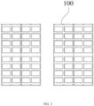
- containers are stored on shelves 100, and the shelves 100 need to be adaptively placed according to the environment of the stockroom.
- the shelves 100 are arranged in two rows, and a goods retrieval passage is provided between the two rows of shelves 100.
- FIG. 1 the increasing demand for the utilization of stockroom area, as illustrated in FIG.
- the shelves 100 in the related art are arranged in four rows, and the goods retrieval passage is provided between the four rows of shelves 100.
- embodiments of the present application provide a container retrieval apparatus, which is illustrated in detail below in combination with specific drawings.
- the container in the present application refers to a box for containing finished or semi-finished products, including but not being limited to a plastic box, a paper box, a wood box, or other common containers.
- FIGS. 3 and 4 illustrate structural schematic view of the container retrieval apparatus provided by embodiments of the present application in different states.
- FIG. 3 illustrates a structural schematic view when an extendable arm 20 of the container retrieval apparatus is not extended.
- a XYZ three-dimensional coordinate system is established with reference to a placement direction of the shelves, in which the Z direction is a vertical direction, the X direction and Y direction are horizontal directions, the X direction points a direction in which goods retrieval is available on the shelf, and the Y direction is perpendicular to the X direction.
- the following first direction refers to the X direction
- the second direction refers to the Z direction
- the third direction refers to the Y direction.
- a major structure of the container retrieval apparatus at least includes a body 10 and an extendable device.
- the body 10 in FIG. 3 has a cuboid structure, and its interior is provided with a corresponding cuboid warehouse 11.
- the warehouse 11 has a goods inlet 12, and this goods inlet 12 may also serve as a goods outlet.
- the container can enter the warehouse 11 from the goods inlet 12 and also can be removed from the warehouse 11 from the goods inlet 12.
- the body 10 includes a cuboid structure enclosed by three side walls and a bottom wall, a side without providing a side wall serves as the goods inlet 12 of the warehouse 11, and an opening direction of the goods inlet 12 is oriented in the X direction, such that goods retrievable from the shelf can enter the warehouse 11 of the body 10 from the goods inlet 12.
- the body 100 illustrated in FIG. 3 has a cuboid shape, which is merely one specific example of the body 10 in the present application.
- the body 10 provided by embodiments of the present application may further employ other shapes, such as a cylinder, an elliptical column shape, a multi-sided body shape, or other shapes.
- the shape of the warehouse 11 may also employ other shapes, such as an elliptical shape, a multi-sided body shape, which only needs to match the container.
- the extendable device provided by embodiments of the present application includes extendable arms arranged at two opposite sides of the goods inlet 12.
- two extendable arms 20 are symmetrically arranged at two sides of the goods inlet 12, and each extendable arm 20 is connected to one side wall of the body 10.
- a space between the two extendable arms 20 is a space where a container to be handled is located.
- the container to be handled can be limited in the space, and the container to be handled can be pulled into the warehouse 11 when the extendable arms 20 retract.
- FIG. 4 For convenience of understanding a structure of the extendable arm 20, explanation is made correspondingly with reference to FIG. 4 below.
- FIG. 4 illustrates a state of the extendable arms 20 when the container retrieval apparatus is retrieving goods.
- the two extendable arms 20 have the same structure, and therefore, one of the extendable arms 20 is taken as an example for explanation.
- the extendable arm 20 includes at least three arms that are slidable relatively, and the extendable arm 20 including three arms is taken as an example for explanation below.
- the three arms include: a first section arm 21, a middle arm 22 and a tail section arm 23.
- the first section arm 21, the middle arm 22 and the tail section arm 23 are arranged in a direction along the side wall of the body 10 to which the first section arm 21 is slidably connected and pointing to an interior of the warehouse 11.
- the first section arm 21 is slidably connected to the body 10
- the middle arm 22 is slidably connected to the first section arm 21
- the tail section arm 21 is slidably connected to the middle arm 22, and sliding directions of the three arms are sliding along the first direction (the X direction). That is, the three arms can slide along a goods retrieval direction, to realize extension and retraction of the extendable arm 20 along the goods retrieval direction.
- the three arms can slide along a goods retrieval direction, to realize extension and retraction of the extendable arm 20 along the goods retrieval direction.
- FIG. 3 when the three arms are retracted, the three arms are overlapped and located in the warehouse 11; with reference to FIG. 4 , when the three arms are extended, the three arms extend along the first direction, and the three arms extend to an outside of the warehouse 11.
- a tail end of the tail section arm 23 away from the body 10 is provided with a shifting finger structure 30, and the shifting finger structure 30 is used to shift the container to be handled.
- the shifting finger structure 30 includes a steering engine 31 fixed to the tail end of the tail section arm 23, and a shifting finger 32 connected to the steering engine 31.
- the steering engine 31 is fixed to the tail end of the tail section arm 23, the shifting finger 32 is connected to the steering engine 31, and the shifting finger 31 can be driven to rotate by the steering engine 31.
- the shifting finger 32 has two positions: an operation position and an avoidance position.
- the steering engine 31 drives the shifting finger 32 to rotate to a horizontal position, and a length direction of the shifting finger 32 is along the Y direction.
- the shifting fingers 32 of the two extendable arms 20 are arranged oppositely, and extend into the space defined by the two extendable arms 20, such that the container to be handled can be pulled when the extendable arms 20 are retracted.
- the shifting fingers 32 do not need to operate, and in this case the shifting fingers 23 are in the avoidance position.
- the shifting fingers 32 under the driving of the steering engine 31 are rotated until their length directions are along the Z direction, to avoid blocking the container to be handled from entering the space between the extendable arms 20 when the extendable arms 20 are inserted into the shelf.
- the shifting finger structure provided by embodiments of the present application may also employ other structures that can shift the container to be handled.
- the steering engine 31 When the steering engine 31 is in use, the steering engine 31 is powered through a cable, and the cable is connected to a power supply apparatus.
- the power supply apparatus may be an accumulator or other power source available, and the power supply apparatus is arranged in the body 10.
- the cable includes a first cable 51 and a second cable 52.
- the first cable 51 and the second cable 52 are tank chain cables.
- the middle arm 22 is provided with an adapter module 53, a first end of the first cable 51 is fixed to the side wall of the body 10, and connected to the power supply apparatus; and a second end of the first cable 51 is connected to the adapter module 53.
- a first end of the second cable 52 is connected to the adapter module 53, and a second end of the second cable 52 is connected with the steering engine 31.
- the adapter module 53 may achieve electrical connection of the first cable 51 and the second cable 52.
- the second cable 52 can be extended and retracted with extension and retraction of the tail section arm 23, and the second cable 52 can be extended and retracted with extension and retraction of the first section arm 21 and the middle arm 22.
- two section cables it is not only ensured that the cable moves following the extension and retraction of the three arms, but also ensured that the connection of the cable with the power supply apparatus and the steering engine 31 is reliable.
- the first cable 51 and the second cable 52 are misaligned in a third direction; in which the third direction is perpendicular to the first direction and the second direction.
- the first cable 51 and the second cable 52 when the first cable 51 and the second cable 52 employ the misaligned arrangement, the first cable 51 and the second cable 52 will not interfere with each other during the extension and the retraction, ensuring that movement spaces for two cables can be realized within limited space, and ensuring that the connection of the cable with the power supply apparatus and the steering engine 31 is reliable when the extendable arms 20 are extended or retracted.
- a sensor assembly 40 may be arranged at the tail end of the tail section arm 23 away from the body 10 for detecting the container, and the sensor assembly 40 may be connected to the control device of the container retrieval apparatus through the cable.
- the second cable 52 is not only connected to the steering engine 31 but also connected to the sensor assembly 40, to send a signal of the sensor assembly 40 to the control device.
- the control device can be used to control the steering engine 31 to drive the shifting finger 32 to rotate to a position where the container to be handled can be shifted when the sensor assembly 40 detects the container to be handled.
- accuracy during handling the container is improved.
- the sensor assembly 40 may contain different sensors.
- the sensor assembly 40 includes through-beam sensors 41 arranged at two tail section arms 23 of the two opposite extendable arms 20, and forward detectors 42 arranged at the tail section arms 23 of the two extendable arms 20. Accuracy when retrieving the goods is improved. When in use, a situation in an extendable direction of the extendable arms 20 can be detected by the forward detectors 42, to ensure that the extendable arms 20 are located two sides of the container to be handled during the extension and the retraction, thereby ensuring accuracy when the extendable arms 20 are extended or retracted.
- the control device can control the steering engine 31 of the shifting finger structure 30 to operate, to get the container to be handled stuck accurately. It can be seen from the above description that when the cable is employed, the extendable arm 20 provided by embodiments of the present application may be provided with the sensor assembly 40, to improve reliability of the whole container retrieval apparatus when in operation.
- control device may be a single chip computer, a PLC or an industrial control computer, and the above-described control device controls components to operate according to detected signal of the sensor assembly 40, which is common functions of the control device, and thus the present application does not further describe signal interaction situations between the sensor assembly 40 and the control device in detail.
- control device when the container retrieval apparatus does not contain the sensor assembly, the control device is further configured to control the shifting finger structure to rotate to a position where the container to be handled can be shifted. In this case, the control device directly sends a control command to the shifting finger structure, and does not need data collected by the sensor assembly.
- control device may also control the extension and retraction of the extendable arm 20.
- control device is connected to the driving device, and control the extension and retraction of the extendable arm 20 through the driving device.
- the driving device includes a driving assembly 63 configured to drive the first section arm 21 of each extendable arm to slide relative to the body 10, and a linkage mechanism configured to drive linkage between adjacent arms of each extendable arm.
- the linkage mechanism can drive the linkage between the arms.
- the linkage mechanism may employ different structures such as a timing belt, a transmission belt.
- the linkage mechanism employs a closed-loop timing belt.
- a specific driving assembly 63 illustrated in FIG. 5 includes a driving motor (not indicated in the figures) arranged at the body 10, and a transmission shaft (not indicated in the figures) connected to the driving motor through a belt (not indicated in the figures).
- the transmission shaft is used to synchronously drive two timing belts 64 arranged at the body 10, and the two timing belts are used to respectively drive the first section arms 21 of the two extendable arms to slide relative to the body 10.
- the driving device further includes a closed-loop timing belt for driving linkage between adjacent arms of each extendable arm.
- the closed-loop timing belt shown in FIG. 5 includes a first timing belt 61 and a second timing belt 62.
- the first timing belt 61 is arranged at the first section arm 21, and the first timing belt 61 is separately fixedly connected to the body 10 and the middle arm 22 and used to drive the middle arm 22 to slide relative to the body 10.
- the second timing belt 62 is arranged at the middle arm 22, and the second timing belt 62 is separately fixedly connected to the first section arm 21 and the tail section arm 23 and used to drive the tail section arm 23 to slide relative to the first section arm 21. As illustrated in FIG.
- an arrangement position of the first timing belt 61 is lower than an arrangement position of the second timing belt 62, and thus space is left for the above-described first cable and second cable, such that the first cable, the second cable and the two timing belts can be arranged along the second direction, the space of the extendable arm can be reasonably utilized, and the space occupied by the cables and the timing belts can be reduced.
- FIG. 6 illustrates a schematic view of fitting between the timing belts and the three arms.
- the first section arm 21 is provided with a first limit rib for limiting oscillation of the first timing belt 61 in a horizontal direction; and the middle arm 22 is provided with a second limit rib 71 for limiting oscillation of the first section arm 61 in the horizontal direction.
- the first limit rib (not illustrated in FIG. 6 due to occlusion of the first timing belt 61) is located in a space enclosed by the first timing belt 61 to support the first timing belt 61 from inside.
- the second limit rib 71 is arranged at a face of the middle arm 22 towards the first section arm 21, the first limit rib and the second limit rib 71 are arranged oppositely, and a gap is defined between the first limit rib and the second limit rib 71 for accommodating the first timing belt 61.
- the oscillation of the first timing belt 61 in the horizontal direction (the Y direction) is limited by cooperation of the first limit rib and the second limit rib 71, ensuring reliability of transmission of the first timing belt 61.
- the second limit rib 71 is provided with two guide protrusions for limiting oscillation of the first timing belt 61 in a vertical direction (the Z direction), and thus oscillation of the first timing belt 61 in the horizontal and vertical directions can be limited to improve reliability of the transmission of the first timing belt 61.
- the middle arm 22 is provided with a third limit rib for limiting oscillation of the second timing belt 62 in the horizontal direction
- the tail section arm 23 is provided with a fourth limit rib 73 for limiting oscillation of the second timing belt 62 in the horizontal direction.
- the third limit rib (not illustrated in FIG. 6 due to occlusion of the second timing belt 62) is located in a space enclosed by the second timing belt 62 to support the second timing belt 62 from inside.
- the fourth limit rib 73 is arranged at a face of the tail section arm 23 towards the middle arm 22, the third limit rib and the fourth limit rib 73 are arranged oppositely, and a gap is defined between the third limit rib and the fourth limit rib 73 for accommodating the second timing belt 62.
- the oscillation of the second timing belt 62 in the horizontal direction (the Y direction) is limited by cooperation of the third limit rib and the fourth limit rib 73, ensuring reliability of transmission of the second timing belt 62.
- the fourth limit rib 73 is provided with two guide protrusions for limiting oscillation of the second timing belt 62 in the vertical direction (the Z direction), and thus oscillation of the second timing belt 62 in the horizontal and vertical directions can be limited to improve reliability of the transmission of the second timing belt 62.
- the first section arm 21 is provided with a fifth limit rib for limiting the second timing belt 62
- the fifth limit rib is arranged at a face of the first section arm 21 towards the middle arm 22, and the fifth limit rib and the third limit rib together limit the oscillation of the second timing belt 62 in the horizontal direction.
- thickness of the arms in the horizontal direction can increase by providing the limit ribs, to enhance structural strength of each arm and improve reliability of the extendable arms when in use.
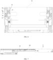
- FIG. 7 a side view of the extendable arm is illustrated in FIG. 7 .
- heights of the three arms of each extendable arm along the second direction satisfy: H2 ⁇ H1 ⁇ H3, in which H1 is a height of the first section arm 21 in the second direction, H2 is a height of the middle arm 22 in the second direction, and H3 is a height of the tail section arm 23 in the second direction. Movement space is left for the cable.
- arrangement positions of the first timing belt and the second timing belt are combined with arrangement positions of the first cable and the second cable.
- Variation in the heights of the three arms in the Z direction ensures that there is enough space on the tail section arm 23 for arranging structures, such as the above-described shifting finger structure, sensor assembly and second cable.
- the tail section arm 23 employs a relatively high height, which improves stability of pulling the container to be handled.
- the middle arm 22 employs a relatively low height, such that there is enough space left under the middle arm 22 for arranging the adapter module and folding the first cable and the second cable.
- the extendable arm provided by embodiments of the present application is configured as an adjustable extendable arm.
- the tail section arm may be provided with a selection mechanism, and the selection mechanism is used to selectively connect the tail section arm with the second timing belt and the middle arm. When the tail section arm and the middle arm are connected by the selection mechanism, the connection between the tail section arm and the second timing belt is released.
- the selection mechanism includes a first magnetic member arranged at the second timing belt, a second magnetic member arranged at the middle arm; and a first electromagnet and a second electromagnet arranged at the tail section arm.
- the first electromagnet can attract the first magnetic member when energized
- the second electromagnet can attract the second magnetic member when energized.
- the first electromagnet and the second electromagnet may be connected to the control device through cables, and operational states of the first electromagnet and the second electromagnet are controlled by the control device. When the three section arms need to be extended, the control device controls the first electromagnet to attract the first magnetic member, and controls the second electromagnet to be deenergized.
- the second timing belt is fixedly connected to the tail section arm, locking between the tail section arm and the middle arm is released, and the tail section arm may slide relative to the middle arm.
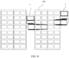
- the second timing belt may drive the linkage of the first section arm and the tail section arm, and all the three arms may be extended. In this case, it can be applied to the arrangement way of the shelves illustrated in FIG. 2 , the container located inside the shelf 100 can be retrieved, as the container retrieval apparatus 1 illustrated in FIG. 8 .
- the control device controls the second electromagnet to attract the second magnetic member, and controls the first electromagnet to be deenergized.
- the tail section arm is fixed to the middle arm by the attraction effect of the second electromagnet and the second magnetic member. Meanwhile, fixed connection between the tail section arm and the second timing belt is released, and when the driving device drives the extendable arm, only the first section arm and the middle arm are extended, and the tail section arm does not extend out from the middle arm, to realize the effect that two arms are extended. It may be applied to the arrangement way of the shelf in FIG. 1 , and applied to retrieve container located on an outer side of shelf 100 in FIG. 2 , as the container retrieval apparatus 2 illustrated in FIG. 8 .
- the arrangement of the selection mechanism can realize selective fixed connection of the tail section arm with the second timing belt or the middle arm.
- different operation ways are selected depending on different operational environment, improving adaptation of the container retrieval apparatus.
- the first magnetic member and the second magnetic member may be iron blocks embedded in the second timing belt and the middle arm, or other materials that can be attracted magnetically. Additionally, the arrangement positions of the first magnetic member and the second magnetic member may be set according to actual needs, and the arrangement positions of the corresponding first electromagnet and second electromagnet may be set according to actual situation, to ensure attractable connection between two corresponding ones, and meet above movement requirements after attraction.
- the container retrieval apparatus provided by embodiments of the present application can employ three arms to retrieve the container, and can realize goods retrieval from deeper warehouse. Additionally, the arrangement of the sensor assembly and the control device can realize accurate goods retrieval.
- embodiments of the present application also provide a robot provided with a container retrieval apparatus as described above.
- the robot retrieves a container by the above-described container retrieval apparatus, realizing accurate goods retrieval.
Landscapes
- Engineering & Computer Science (AREA)
- Transportation (AREA)
- Structural Engineering (AREA)
- Mechanical Engineering (AREA)
- Civil Engineering (AREA)
- Life Sciences & Earth Sciences (AREA)
- Geology (AREA)
- Chemical & Material Sciences (AREA)
- Combustion & Propulsion (AREA)
- Warehouses Or Storage Devices (AREA)
- Manipulator (AREA)
Abstract
Description
- This application claims priority to
Chinese Patent Application Serial No. 202010345452.9, entitled "a container retrieval apparatus" and filed with National Intellectual Property Administration of PRC on April 27, 2020 - The present application relates to a field of logistics, and more particular to a container retrieval apparatus and a robot.
- During handling of the robots in the related logistics filed, initial AGV robots handle shelves. With the development of the technologies, most manufactures start to handle work bins, paper boxes or other goods storage apparatus. Existing telescopic forks for retrieving containers and paper boxes most have a mode of first stage being fixed, and second stage being telescopic. However, with changes in arrangement way of the shelves, the handling apparatus in the related art cannot retrieve containers at an inner side and an outer side of the shelf, and cannot meet handling requirements.
- In view of this, the present application provides a container retrieval apparatus and a robot, to improve handling effect.
- The present application provides a container retrieval apparatus. The container retrieval apparatus includes a body, a telescopic device, a control device and a driving device. In which,
- the body defines a warehouse therein, the warehouse has a goods inlet;
- the extendable device includes extendable arms arranged on two opposite sides of the goods inlet; each extendable arm includes at least three arms capable of sliding relatively, the at least three arms are extendable in a first direction, the first direction being a goods inlet and outlet direction of the warehouse; wherein a first section arm of the at least three arms is slidably connected to the body, a tail end of a tail section arm away from the body is provided with a shifting finger structure;
- the driving device includes a driving assembly configured to drive the first section arm of each extendable arm to slide relative to the body, and a linkage mechanism configured to drive linkage between adjacent arms of each extendable arm;
- and the control device is configured to control the shifting finger structure to rotate to a position where a container to be handled can be shifted.
- In the above-described technical solution, by using the at least three arms to retrieve a container, goods can be retrieved from a deeper warehouse.
- In a specific implementable solution, the linkage mechanism is a closed-loop timing belt. The linkage between the arms is driven by the closed-loop timing belt.
- In a specific implementable solution, the at least three arms are three arms, the closed-loop timing belt includes a first timing belt and a second timing belt;
- the first timing belt is arranged at the first section arm, and the first timing belt is fixedly connected to the body and a middle arm of the three arms separately, and configured to drive the middle arm to slide relative to the body;
- the second timing belt is arranged at the middle arm, and the second timing belt is fixedly connected to the first section arm and the tail section arm separately, and configured to drive the tail section arm to slide relative to the first section arm; in which,
- the tail section arm is provided with a selection mechanism configured to selectively connect the tail section arm with the second timing belt and the middle arm; and fixed connection between the tail section arm and the second timing belt is released when the tail section arm is fixedly connected to the middle arm by the selection mechanism. The arrangement of the selection mechanism can realize that three arms or two section arms are selectively extended, to realize goods retrieval from the warehouse of different depths.
- In a specific implementable solution, the selection mechanism includes a first magnetic member arranged at the second timing belt, a second magnetic member arranged at the middle arm; and a first electromagnet and a second electromagnet arranged at the tail section arm. In which, the first electromagnet can attract the first magnetic member when energized, and the second electromagnet can attract the second magnetic member when energized. Selective fixed connection of the tail section arm with the second timing belt or the middle arm is realized.
- In a specific implementable solution, the first section arm is provided with a first limit rib configured to limit oscillation of the first timing belt in a horizontal direction;
- the middle arm is provided with a second limit rib configured to limit oscillation of the first timing belt in the horizontal direction, and a third limit rib configured to limit oscillation of the second timing belt in the horizontal direction;
- and the tail section arm is provided with a fourth limit rib configured to limit oscillation of the second timing belt in the horizontal direction. The arrangement of limit ribs can improve stability of the timing belts when movement.
- In a specific implementable solution, the first limit rib and the second limit rib are arranged oppositely, and the first limit rib and the second limit rib define a gap therebetween for accommodating the first timing belt; and the third limit rib and the fourth limit rib are arranged oppositely, and the third limit rib and the fourth limit rib define a gap therebetween for accommodating the second timing belt. The arrangement of limit ribs can improve stability of the timing belts when movement.
- In a specific implementable solution, the second limit rib is provided with two guide protrusions configured to limit oscillation of the first timing belt in a vertical direction;
the fourth limit rib is provided with two guide protrusions configured to limit oscillation of the second timing belt in the vertical direction. The arrangement of limit ribs can improve stability of the timing belts when movement. - In a specific implementable solution, in a second direction, an arrangement position of the first timing belt is lower than an arrangement position of the second timing belt;
and the second direction is perpendicular to the first direction. Movement space is left for the cable. - In a specific implementable solution, heights of the three arms of each extendable arm in the second direction satisfy:
H2≤H1<H3, in which H1 is a height of the first section arm in the second direction, H2 is a height of the middle arm in the second direction, and H3 is a height of the tail section arm in the second direction. Movement space is left for the cable. - In a specific implementable solution, the body is provided with a power supply device; the shifting finger structure includes a steering engine fixed to the tail end of the tail section arm, a shifting finger connected to the steering engine, and a cable connected to the steering engine, the cable being connected to the power supply apparatus. The shifting finger structure is driven by the steering engine, reducing mechanical abrasion.
- In a specific implementable solution, the cable includes a first cable and a second cable, the first cable and the second cable are each a tank chain cable;
- the at least three arms are three arms, and a middle arm of the three arms is provided with an adapter module;
- the first cable has a first end fixed to a side wall of the body, and the first cable has a second end connected to the adapter module;
- the second cable has a first end connected to the adapter module, and the second cable has a second end connected to the steering engine and the sensor assembly. Arrangement of the cable is facilitated.
- In a specific implementable solution, in each extendable arm, the first cable and the second cable are misaligned in a third direction;
and the third direction is perpendicular to the first direction and the second direction. Arrangement of the cable is facilitated. - In a specific implementable solution, the tail section arm is provided with a sensor assembly configured to detect the container to be handled;
- the sensor assembly is connected to the control device through the cable;
- and the control device is further configured to control the shifting finger structure to rotate to a position where the container to be handled can be shifted, when the sensor assembly detects the container to be handled. Thus, accuracy of handling is improved.
- In a specific implementable solution, the sensor assembly includes through-beam sensors arranged at two tail section arms of two opposite extendable arms, and forward detectors arranged at tail section arms of the two extendable arms. Accuracy when retrieving the goods is improved.
- In a specific implementable solution, a robot including a container retrieval apparatus according to any of the above-described implementations is provided.
- In order to clearly explain technical solutions of embodiments of the present disclosure, the accompanying drawings used in the embodiments are briefly introduced below, the accompanying drawings herein are incorporated into the specification and constitute a part of the specification. Theses accompanying drawings illustrate embodiments conform to the present disclosure and are used to explain the technical solutions of the present disclosure together with the specification. It should be understood that the following accompanying drawings only illustrate some embodiments of the present disclosure, and thus should not be regarded as limitation to the scope, and a person having ordinary skill in the art can obtain other related drawings according to these drawings without paying creative effort.
-
FIG. 1 is a schematic view of an application scenario of a container retrieval apparatus according to an embodiment of the present application; -
FIG. 2 is a schematic view of an application scenario of a container retrieval apparatus according to an embodiment of the present application; -
FIG. 3 is a schematic view of a container retrieval apparatus according to an embodiment of the present application in a state where no goods is retrieved; -
FIG. 4 is a schematic view of a container retrieval apparatus according to an embodiment of the present application in a state where goods are retrieved; -
FIG. 5 is a structural schematic view of a driving device according to an embodiment of the present application; -
FIG. 6 is a schematic view of fitting between an extendable arm and a driving device according to an embodiment of the present application; -
FIG. 7 is a structural schematic view of an extendable arm according to an embodiment of the present application; and -
FIG. 8 is a schematic view of an application of a container retrieval apparatus according to an embodiment of the present application. - In order to make the purpose, technical solutions and advantages of the present application clearer, the present application will be further described below with reference to the accompanying drawings. It is apparent that the described embodiments are only a part of the embodiments of the present application, and not all of them. Based on the embodiments of the present application, all other embodiments obtained by those skilled in the art without paying creative efforts, fall into the protection scope of the present application.
- For convenience of understanding a container retrieval apparatus provided by embodiments of the present application, the container retrieval apparatus provided by embodiments of the present application will be illustrated in detail below in combination with
FIGS. 1 and2 . As illustrated inFIGS. 1 and2 , the container retrieval apparatus provided by embodiments of the present application is used to handle containers in a stockroom. In a stockroom, containers are stored onshelves 100, and theshelves 100 need to be adaptively placed according to the environment of the stockroom. As illustrated inFIG. 1 , theshelves 100 are arranged in two rows, and a goods retrieval passage is provided between the two rows ofshelves 100. However, with the increasing demand for the utilization of stockroom area, as illustrated inFIG. 2 , theshelves 100 in the related art are arranged in four rows, and the goods retrieval passage is provided between the four rows ofshelves 100. In order to adapt to the way of retrieving goods in a stockroom with arrangement ofshelves 100 in four rows, embodiments of the present application provide a container retrieval apparatus, which is illustrated in detail below in combination with specific drawings. - First, the container is explained, the container in the present application refers to a box for containing finished or semi-finished products, including but not being limited to a plastic box, a paper box, a wood box, or other common containers.
- Reference is also made to
FIGS. 3 and4 .FIGS. 3 and4 illustrate structural schematic view of the container retrieval apparatus provided by embodiments of the present application in different states. - Reference is first made to
FIG. 3. FIG. 3 illustrates a structural schematic view when anextendable arm 20 of the container retrieval apparatus is not extended. For convenience of understanding the container retrieval apparatus provided by embodiments of the present application, a XYZ three-dimensional coordinate system is established with reference to a placement direction of the shelves, in which the Z direction is a vertical direction, the X direction and Y direction are horizontal directions, the X direction points a direction in which goods retrieval is available on the shelf, and the Y direction is perpendicular to the X direction. For consistence with description of a first direction, a second direction and a third direction hereinafter, the following first direction refers to the X direction, the second direction refers to the Z direction, and the third direction refers to the Y direction. - Continuing to refer to
FIG. 3 , a major structure of the container retrieval apparatus at least includes abody 10 and an extendable device. First, thebody 10 is explained, thebody 10 inFIG. 3 has a cuboid structure, and its interior is provided with a correspondingcuboid warehouse 11. Thewarehouse 11 has agoods inlet 12, and thisgoods inlet 12 may also serve as a goods outlet. The container can enter thewarehouse 11 from thegoods inlet 12 and also can be removed from thewarehouse 11 from thegoods inlet 12. In combination with a structure inFIG. 3 , thebody 10 includes a cuboid structure enclosed by three side walls and a bottom wall, a side without providing a side wall serves as thegoods inlet 12 of thewarehouse 11, and an opening direction of thegoods inlet 12 is oriented in the X direction, such that goods retrievable from the shelf can enter thewarehouse 11 of thebody 10 from thegoods inlet 12. It should be understood that thebody 100 illustrated inFIG. 3 has a cuboid shape, which is merely one specific example of thebody 10 in the present application. Thebody 10 provided by embodiments of the present application may further employ other shapes, such as a cylinder, an elliptical column shape, a multi-sided body shape, or other shapes. The shape of thewarehouse 11 may also employ other shapes, such as an elliptical shape, a multi-sided body shape, which only needs to match the container. - Continuing to refer to
FIG. 3 , the extendable device provided by embodiments of the present application includes extendable arms arranged at two opposite sides of thegoods inlet 12. With reference to a structure illustrated inFIG. 3 , twoextendable arms 20 are symmetrically arranged at two sides of thegoods inlet 12, and eachextendable arm 20 is connected to one side wall of thebody 10. A space between the twoextendable arms 20 is a space where a container to be handled is located. By the twoextendable arms 20, the container to be handled can be limited in the space, and the container to be handled can be pulled into thewarehouse 11 when theextendable arms 20 retract. For convenience of understanding a structure of theextendable arm 20, explanation is made correspondingly with reference toFIG. 4 below. -
FIG. 4 illustrates a state of theextendable arms 20 when the container retrieval apparatus is retrieving goods. The twoextendable arms 20 have the same structure, and therefore, one of theextendable arms 20 is taken as an example for explanation. Theextendable arm 20 includes at least three arms that are slidable relatively, and theextendable arm 20 including three arms is taken as an example for explanation below. With reference toFIGS. 3 and4 , the three arms include: afirst section arm 21, amiddle arm 22 and atail section arm 23. Thefirst section arm 21, themiddle arm 22 and thetail section arm 23 are arranged in a direction along the side wall of thebody 10 to which thefirst section arm 21 is slidably connected and pointing to an interior of thewarehouse 11. Thefirst section arm 21 is slidably connected to thebody 10, themiddle arm 22 is slidably connected to thefirst section arm 21, thetail section arm 21 is slidably connected to themiddle arm 22, and sliding directions of the three arms are sliding along the first direction (the X direction). That is, the three arms can slide along a goods retrieval direction, to realize extension and retraction of theextendable arm 20 along the goods retrieval direction. With reference toFIG. 3 , when the three arms are retracted, the three arms are overlapped and located in thewarehouse 11; with reference toFIG. 4 , when the three arms are extended, the three arms extend along the first direction, and the three arms extend to an outside of thewarehouse 11. - Continuing to refer to
FIG. 4 , a tail end of thetail section arm 23 away from thebody 10 is provided with a shifting finger structure 30, and the shifting finger structure 30 is used to shift the container to be handled. As one specific example, the shifting finger structure 30 includes asteering engine 31 fixed to the tail end of thetail section arm 23, and a shifting finger 32 connected to thesteering engine 31. With reference toFIG. 4 , thesteering engine 31 is fixed to the tail end of thetail section arm 23, the shifting finger 32 is connected to thesteering engine 31, and the shiftingfinger 31 can be driven to rotate by thesteering engine 31. The shifting finger 32 has two positions: an operation position and an avoidance position. When the shifting finger 32 operates, thesteering engine 31 drives the shifting finger 32 to rotate to a horizontal position, and a length direction of the shifting finger 32 is along the Y direction. The shifting fingers 32 of the twoextendable arms 20 are arranged oppositely, and extend into the space defined by the twoextendable arms 20, such that the container to be handled can be pulled when theextendable arms 20 are retracted. When theextendable arm 20 are inserted into the shelf, the shifting fingers 32 do not need to operate, and in this case the shiftingfingers 23 are in the avoidance position. The shifting fingers 32 under the driving of thesteering engine 31 are rotated until their length directions are along the Z direction, to avoid blocking the container to be handled from entering the space between theextendable arms 20 when theextendable arms 20 are inserted into the shelf. When thesteering engine 31 is employed to drive the shifting finger 32, mechanical structure abrasion in the related art does not exist, to improve operational reliability of the shifting finger structure 30, compared to a situation in the related art where a mechanical structure is employed to drive the shifting finger 32. Certainly, the shifting finger structure provided by embodiments of the present application may also employ other structures that can shift the container to be handled. - When the
steering engine 31 is in use, thesteering engine 31 is powered through a cable, and the cable is connected to a power supply apparatus. The power supply apparatus may be an accumulator or other power source available, and the power supply apparatus is arranged in thebody 10. As illustrated inFIG. 4 , the cable includes afirst cable 51 and asecond cable 52. Thefirst cable 51 and thesecond cable 52 are tank chain cables. Themiddle arm 22 is provided with an adapter module 53, a first end of thefirst cable 51 is fixed to the side wall of thebody 10, and connected to the power supply apparatus; and a second end of thefirst cable 51 is connected to the adapter module 53. A first end of thesecond cable 52 is connected to the adapter module 53, and a second end of thesecond cable 52 is connected with thesteering engine 31. The adapter module 53 may achieve electrical connection of thefirst cable 51 and thesecond cable 52. When the above-described structure is employed, thesecond cable 52 can be extended and retracted with extension and retraction of thetail section arm 23, and thesecond cable 52 can be extended and retracted with extension and retraction of thefirst section arm 21 and themiddle arm 22. When two section cables are employed, it is not only ensured that the cable moves following the extension and retraction of the three arms, but also ensured that the connection of the cable with the power supply apparatus and thesteering engine 31 is reliable. In a specific implementable solution, in eachextendable arm 20, thefirst cable 51 and thesecond cable 52 are misaligned in a third direction; in which the third direction is perpendicular to the first direction and the second direction. As illustrated inFIG. 4 , when thefirst cable 51 and thesecond cable 52 employ the misaligned arrangement, thefirst cable 51 and thesecond cable 52 will not interfere with each other during the extension and the retraction, ensuring that movement spaces for two cables can be realized within limited space, and ensuring that the connection of the cable with the power supply apparatus and thesteering engine 31 is reliable when theextendable arms 20 are extended or retracted. - As one optional implementation, when the shifting finger structure 30 provided by embodiments of the present application is powered by employing the cable, a
sensor assembly 40 may be arranged at the tail end of thetail section arm 23 away from thebody 10 for detecting the container, and thesensor assembly 40 may be connected to the control device of the container retrieval apparatus through the cable. When two-stage cable is employed, thesecond cable 52 is not only connected to thesteering engine 31 but also connected to thesensor assembly 40, to send a signal of thesensor assembly 40 to the control device. The control device can be used to control thesteering engine 31 to drive the shifting finger 32 to rotate to a position where the container to be handled can be shifted when thesensor assembly 40 detects the container to be handled. Thus, accuracy during handling the container is improved. When thesensor assembly 40 is provided, thesensor assembly 40 may contain different sensors. For example, thesensor assembly 40 includes through-beam sensors 41 arranged at twotail section arms 23 of the two oppositeextendable arms 20, andforward detectors 42 arranged at thetail section arms 23 of the twoextendable arms 20. Accuracy when retrieving the goods is improved. When in use, a situation in an extendable direction of theextendable arms 20 can be detected by theforward detectors 42, to ensure that theextendable arms 20 are located two sides of the container to be handled during the extension and the retraction, thereby ensuring accuracy when theextendable arms 20 are extended or retracted. In addition, it can be determined whether the positions of the shifting fingers 32 are in place, and whether the container to be handled is stuck when the shifting fingers 32 are rotated, by the detection between the through-beam sensors 41. After receiving the above-described signal, the control device can control thesteering engine 31 of the shifting finger structure 30 to operate, to get the container to be handled stuck accurately. It can be seen from the above description that when the cable is employed, theextendable arm 20 provided by embodiments of the present application may be provided with thesensor assembly 40, to improve reliability of the whole container retrieval apparatus when in operation. - It should be understood that, the above-described control device may be a single chip computer, a PLC or an industrial control computer, and the above-described control device controls components to operate according to detected signal of the
sensor assembly 40, which is common functions of the control device, and thus the present application does not further describe signal interaction situations between thesensor assembly 40 and the control device in detail. - In one optional implementing solution, when the container retrieval apparatus does not contain the sensor assembly, the control device is further configured to control the shifting finger structure to rotate to a position where the container to be handled can be shifted. In this case, the control device directly sends a control command to the shifting finger structure, and does not need data collected by the sensor assembly.
- In one optional implementing solution, the control device may also control the extension and retraction of the
extendable arm 20. Specifically, the control device is connected to the driving device, and control the extension and retraction of theextendable arm 20 through the driving device. - As illustrated in
FIG. 5 , when the extendable arm is in operation, its extension and retraction are controlled by the driving device. The driving device includes a drivingassembly 63 configured to drive thefirst section arm 21 of each extendable arm to slide relative to thebody 10, and a linkage mechanism configured to drive linkage between adjacent arms of each extendable arm. The linkage mechanism can drive the linkage between the arms. For example, the linkage mechanism may employ different structures such as a timing belt, a transmission belt. As one specific example, the linkage mechanism employs a closed-loop timing belt. - A
specific driving assembly 63 illustrated inFIG. 5 includes a driving motor (not indicated in the figures) arranged at thebody 10, and a transmission shaft (not indicated in the figures) connected to the driving motor through a belt (not indicated in the figures). The transmission shaft is used to synchronously drive two timingbelts 64 arranged at thebody 10, and the two timing belts are used to respectively drive thefirst section arms 21 of the two extendable arms to slide relative to thebody 10. In addition, the driving device further includes a closed-loop timing belt for driving linkage between adjacent arms of each extendable arm. The closed-loop timing belt shown inFIG. 5 includes afirst timing belt 61 and asecond timing belt 62. Thefirst timing belt 61 is arranged at thefirst section arm 21, and thefirst timing belt 61 is separately fixedly connected to thebody 10 and themiddle arm 22 and used to drive themiddle arm 22 to slide relative to thebody 10. Thesecond timing belt 62 is arranged at themiddle arm 22, and thesecond timing belt 62 is separately fixedly connected to thefirst section arm 21 and thetail section arm 23 and used to drive thetail section arm 23 to slide relative to thefirst section arm 21. As illustrated inFIG. 5 , along the second direction (the Z direction), an arrangement position of thefirst timing belt 61 is lower than an arrangement position of thesecond timing belt 62, and thus space is left for the above-described first cable and second cable, such that the first cable, the second cable and the two timing belts can be arranged along the second direction, the space of the extendable arm can be reasonably utilized, and the space occupied by the cables and the timing belts can be reduced. - Reference is also made to
FIG. 6, and FIG. 6 illustrates a schematic view of fitting between the timing belts and the three arms. As one optional solution, thefirst section arm 21 is provided with a first limit rib for limiting oscillation of thefirst timing belt 61 in a horizontal direction; and themiddle arm 22 is provided with a second limit rib 71 for limiting oscillation of thefirst section arm 61 in the horizontal direction. The first limit rib (not illustrated inFIG. 6 due to occlusion of the first timing belt 61) is located in a space enclosed by thefirst timing belt 61 to support thefirst timing belt 61 from inside. The second limit rib 71 is arranged at a face of themiddle arm 22 towards thefirst section arm 21, the first limit rib and the second limit rib 71 are arranged oppositely, and a gap is defined between the first limit rib and the second limit rib 71 for accommodating thefirst timing belt 61. The oscillation of thefirst timing belt 61 in the horizontal direction (the Y direction) is limited by cooperation of the first limit rib and the second limit rib 71, ensuring reliability of transmission of thefirst timing belt 61. Additionally, as one optional solution, the second limit rib 71 is provided with two guide protrusions for limiting oscillation of thefirst timing belt 61 in a vertical direction (the Z direction), and thus oscillation of thefirst timing belt 61 in the horizontal and vertical directions can be limited to improve reliability of the transmission of thefirst timing belt 61. - Continuing to refer to
FIG. 6 , as one optional solution, themiddle arm 22 is provided with a third limit rib for limiting oscillation of thesecond timing belt 62 in the horizontal direction, and thetail section arm 23 is provided with afourth limit rib 73 for limiting oscillation of thesecond timing belt 62 in the horizontal direction. The third limit rib (not illustrated inFIG. 6 due to occlusion of the second timing belt 62) is located in a space enclosed by thesecond timing belt 62 to support thesecond timing belt 62 from inside. Thefourth limit rib 73 is arranged at a face of thetail section arm 23 towards themiddle arm 22, the third limit rib and thefourth limit rib 73 are arranged oppositely, and a gap is defined between the third limit rib and thefourth limit rib 73 for accommodating thesecond timing belt 62. The oscillation of thesecond timing belt 62 in the horizontal direction (the Y direction) is limited by cooperation of the third limit rib and thefourth limit rib 73, ensuring reliability of transmission of thesecond timing belt 62. Additionally, as one optional solution, thefourth limit rib 73 is provided with two guide protrusions for limiting oscillation of thesecond timing belt 62 in the vertical direction (the Z direction), and thus oscillation of thesecond timing belt 62 in the horizontal and vertical directions can be limited to improve reliability of the transmission of thesecond timing belt 62. - As one optional solution, the
first section arm 21 is provided with a fifth limit rib for limiting thesecond timing belt 62, the fifth limit rib is arranged at a face of thefirst section arm 21 towards themiddle arm 22, and the fifth limit rib and the third limit rib together limit the oscillation of thesecond timing belt 62 in the horizontal direction. - Additionally, when the above-described limit ribs are employed, thickness of the arms in the horizontal direction (the Y direction) can increase by providing the limit ribs, to enhance structural strength of each arm and improve reliability of the extendable arms when in use.
- As illustrated in
FIG. 7 , a side view of the extendable arm is illustrated inFIG. 7 . As one optional solution, heights of the three arms of each extendable arm along the second direction satisfy: H2≤H1 <H3, in which H1 is a height of thefirst section arm 21 in the second direction, H2 is a height of themiddle arm 22 in the second direction, and H3 is a height of thetail section arm 23 in the second direction. Movement space is left for the cable. When the above-described structure is employed, arrangement positions of the first timing belt and the second timing belt are combined with arrangement positions of the first cable and the second cable. Variation in the heights of the three arms in the Z direction ensures that there is enough space on thetail section arm 23 for arranging structures, such as the above-described shifting finger structure, sensor assembly and second cable. Meanwhile, thetail section arm 23 employs a relatively high height, which improves stability of pulling the container to be handled. Themiddle arm 22 employs a relatively low height, such that there is enough space left under themiddle arm 22 for arranging the adapter module and folding the first cable and the second cable. When thefirst section arm 21 employs the above-described height, themiddle arm 22 and the tail end arm can be stably supported, and meanwhile a space is left for arranging structures such as the above-described first cable and first timing belt. - In order to improve universality of the container retrieval apparatus provided by embodiments of the present application, and to adapt the arrangement way of the shelves illustrated in
FIGS. 1 and2 , as one expanded example, the extendable arm provided by embodiments of the present application is configured as an adjustable extendable arm. For example, the tail section arm may be provided with a selection mechanism, and the selection mechanism is used to selectively connect the tail section arm with the second timing belt and the middle arm. When the tail section arm and the middle arm are connected by the selection mechanism, the connection between the tail section arm and the second timing belt is released. In a specific implementable solution, the selection mechanism includes a first magnetic member arranged at the second timing belt, a second magnetic member arranged at the middle arm; and a first electromagnet and a second electromagnet arranged at the tail section arm. In which, the first electromagnet can attract the first magnetic member when energized, and the second electromagnet can attract the second magnetic member when energized. The first electromagnet and the second electromagnet may be connected to the control device through cables, and operational states of the first electromagnet and the second electromagnet are controlled by the control device. When the three section arms need to be extended, the control device controls the first electromagnet to attract the first magnetic member, and controls the second electromagnet to be deenergized. In this case, the second timing belt is fixedly connected to the tail section arm, locking between the tail section arm and the middle arm is released, and the tail section arm may slide relative to the middle arm. When the driving device is in operation, the second timing belt may drive the linkage of the first section arm and the tail section arm, and all the three arms may be extended. In this case, it can be applied to the arrangement way of the shelves illustrated inFIG. 2 , the container located inside theshelf 100 can be retrieved, as thecontainer retrieval apparatus 1 illustrated inFIG. 8 . When two arms need to be extended, the control device controls the second electromagnet to attract the second magnetic member, and controls the first electromagnet to be deenergized. In this case, the tail section arm is fixed to the middle arm by the attraction effect of the second electromagnet and the second magnetic member. Meanwhile, fixed connection between the tail section arm and the second timing belt is released, and when the driving device drives the extendable arm, only the first section arm and the middle arm are extended, and the tail section arm does not extend out from the middle arm, to realize the effect that two arms are extended. It may be applied to the arrangement way of the shelf inFIG. 1 , and applied to retrieve container located on an outer side ofshelf 100 inFIG. 2 , as thecontainer retrieval apparatus 2 illustrated inFIG. 8 . - It can be seen from the above description that, the arrangement of the selection mechanism can realize selective fixed connection of the tail section arm with the second timing belt or the middle arm. Thus, different operation ways are selected depending on different operational environment, improving adaptation of the container retrieval apparatus.
- In one optional implementing solution, the first magnetic member and the second magnetic member may be iron blocks embedded in the second timing belt and the middle arm, or other materials that can be attracted magnetically. Additionally, the arrangement positions of the first magnetic member and the second magnetic member may be set according to actual needs, and the arrangement positions of the corresponding first electromagnet and second electromagnet may be set according to actual situation, to ensure attractable connection between two corresponding ones, and meet above movement requirements after attraction.
- It can be seen from the above description, the container retrieval apparatus provided by embodiments of the present application can employ three arms to retrieve the container, and can realize goods retrieval from deeper warehouse. Additionally, the arrangement of the sensor assembly and the control device can realize accurate goods retrieval.
- Based on the above-described container retrieval apparatus, embodiments of the present application also provide a robot provided with a container retrieval apparatus as described above. The robot retrieves a container by the above-described container retrieval apparatus, realizing accurate goods retrieval.
- It is apparent that various modifications and variations can be made to the present application by a person skilled in the art, without departing from spirit and scope of the present application. Thus, if these modifications and variations of the present application fall within the scope of the claims or their equivalent technologies of the present application, the present application is intended to contain these modifications and variations.
Claims (14)
- A container retrieval apparatus, comprising: a body, an extendable device, a control device and a driving device, whereinthe body defines a warehouse therein, the warehouse has a goods inlet;the extendable device comprises extendable arms arranged on two opposite sides of the goods inlet; each extendable arm comprises at least three arms capable of sliding relatively, the at least three arms are extendable in a first direction, the first direction being a goods inlet and outlet direction of the warehouse; wherein a first section arm of the at least three arms is slidably connected to the body, a tail end of a tail section arm away from the body is provided with a shifting finger structure;the driving device comprises a driving assembly configured to drive the first section arm of each extendable arm to slide relative to the body, and a linkage mechanism configured to drive linkage between adjacent arms of each extendable arm;and the control device is configured to control the shifting finger structure to rotate to a position where a container to be handled can be shifted.
- The container retrieval apparatus according to claim 1, wherein the linkage mechanism is a closed-loop timing belt.
- The container retrieval apparatus according to claim 2, wherein the at least three arms are three arms, the closed-loop timing belt comprises a first timing belt and a second timing belt;the first timing belt is arranged at the first section arm, and the first timing belt is fixedly connected to the body and a middle arm of the three arms separately, and configured to drive the middle arm to slide relative to the body;the second timing belt is arranged at the middle arm, and the second timing belt is fixedly connected to the first section arm and the tail section arm separately, and configured to drive the tail section arm to slide relative to the first section arm; wherein,the tail section arm is provided with a selection mechanism configured to selectively connect the tail section arm with the second timing belt and the middle arm; and fixed connection between the tail section arm and the second timing belt is released when the tail section arm is fixedly connected to the middle arm by the selection mechanism.
- The container retrieval apparatus according to claim 3, wherein the first section arm is provided with a first limit rib configured to limit oscillation of the first timing belt in a horizontal direction;the middle arm is provided with a second limit rib configured to limit oscillation of the first timing belt in the horizontal direction, and a third limit rib configured to limit oscillation of the second timing belt in the horizontal direction; andthe tail section arm is provided with a fourth limit rib configured to limit oscillation of the second timing belt in the horizontal direction.
- The container retrieval apparatus according to claim 4, wherein the first limit rib and the second limit rib are arranged oppositely, and the first limit rib and the second limit rib define a gap therebetween for accommodating the first timing belt; and
the third limit rib and the fourth limit rib are arranged oppositely, and the third limit rib and the fourth limit rib define a gap therebetween for accommodating the second timing belt. - The container retrieval apparatus according to claim 4 or 5, wherein the second limit rib is provided with two guide protrusions configured to limit oscillation of the first timing belt in a vertical direction; and/or,
the fourth limit rib is provided with two guide protrusions configured to limit oscillation of the second timing belt in the vertical direction. - The container retrieval apparatus according to any one of claims 3 to 6, wherein in a second direction, an arrangement position of the first timing belt is lower than an arrangement position of the second timing belt; and
the second direction is perpendicular to the first direction. - The container retrieval apparatus according to claim 7, wherein heights of the three arms of each extendable arm in the second direction satisfy:
H2<H1 <H3, wherein H1 is a height of the first section arm in the second direction, H2 is a height of the middle arm in the second direction, and H3 is a height of the tail section arm in the second direction. - The container retrieval apparatus according to any one of claims 1 to 8, wherein the body is provided with a power supply device; and
the shifting finger structure comprises a steering engine fixed to the tail end of the tail section arm, a shifting finger connected to the steering engine, and a cable connected to the steering engine, the cable being connected to the power supply apparatus. - The container retrieval apparatus according to claim 9, whereinthe cable comprises a first cable and a second cable, the first cable and the second cable are each a tank chain cable;the at least three arms are three arms, and a middle arm of the three arms is provided with an adapter module;the first cable has a first end fixed to a side wall of the body, and the first cable has a second end connected to the adapter module;the second cable has a first end connected to the adapter module, and the second cable has a second end connected to the steering engine and the sensor assembly.
- The container retrieval apparatus according to claim 10, wherein in each extendable arm, the first cable and the second cable are misaligned in a third direction; and
the third direction is perpendicular to the first direction and the second direction. - The container retrieval apparatus according to any one of claims 9 to 11, wherein the tail section arm is provided with a sensor assembly configured to detect the container to be handled;the sensor assembly is connected to the control device through the cable; andthe control device is further configured to control the shifting finger structure to rotate to a position where the container to be handled can be shifted, when the sensor assembly detects the container to be handled.
- The container retrieval apparatus according to claim 12, wherein the sensor assembly comprises through-beam sensors arranged to two tail section arms of two opposite extendable arms, and forward detectors arranged to tail section arms of the two extendable arms.
- A robot, comprising a container retrieval apparatus according to any one of claims 1 to 13.
Priority Applications (1)
| Application Number | Priority Date | Filing Date | Title |
|---|---|---|---|
| EP24206194.3A EP4467508A3 (en) | 2020-04-27 | 2020-10-19 | Container retrieval apparatus and robot |
Applications Claiming Priority (2)
| Application Number | Priority Date | Filing Date | Title |
|---|---|---|---|
| CN202010345452.9A CN111348367B (en) | 2020-04-27 | 2020-04-27 | Get packing box equipment |
| PCT/CN2020/121931 WO2021218057A1 (en) | 2020-04-27 | 2020-10-19 | Container retrieval apparatus and robot |
Related Child Applications (2)
| Application Number | Title | Priority Date | Filing Date |
|---|---|---|---|
| EP24206194.3A Division-Into EP4467508A3 (en) | 2020-04-27 | 2020-10-19 | Container retrieval apparatus and robot |
| EP24206194.3A Division EP4467508A3 (en) | 2020-04-27 | 2020-10-19 | Container retrieval apparatus and robot |
Publications (3)
| Publication Number | Publication Date |
|---|---|
| EP4144668A1 true EP4144668A1 (en) | 2023-03-08 |
| EP4144668A4 EP4144668A4 (en) | 2023-10-18 |
| EP4144668B1 EP4144668B1 (en) | 2024-12-04 |
Family
ID=71191733
Family Applications (2)
| Application Number | Title | Priority Date | Filing Date |
|---|---|---|---|
| EP20934052.0A Active EP4144668B1 (en) | 2020-04-27 | 2020-10-19 | Container retrieval apparatus and robot |
| EP24206194.3A Pending EP4467508A3 (en) | 2020-04-27 | 2020-10-19 | Container retrieval apparatus and robot |
Family Applications After (1)
| Application Number | Title | Priority Date | Filing Date |
|---|---|---|---|
| EP24206194.3A Pending EP4467508A3 (en) | 2020-04-27 | 2020-10-19 | Container retrieval apparatus and robot |
Country Status (5)
| Country | Link |
|---|---|
| US (2) | US12116204B2 (en) |
| EP (2) | EP4144668B1 (en) |
| CN (3) | CN111348367B (en) |
| DE (1) | DE202020006115U1 (en) |
| WO (1) | WO2021218057A1 (en) |
Cited By (1)
| Publication number | Priority date | Publication date | Assignee | Title |
|---|---|---|---|---|
| EP4163230A4 (en) * | 2020-06-05 | 2024-06-12 | Beijing Geekplus Technology Co., Ltd. | Goods box carrying robot and method for using same |
Families Citing this family (6)
| Publication number | Priority date | Publication date | Assignee | Title |
|---|---|---|---|---|
| CN111348367B (en) | 2020-04-27 | 2025-06-10 | 北京极智嘉科技股份有限公司 | Get packing box equipment |
| JP7298589B2 (en) * | 2020-12-15 | 2023-06-27 | 株式会社ダイフク | Goods storage facility |
| CN116199155A (en) * | 2021-12-01 | 2023-06-02 | 泰科电子(上海)有限公司 | Pallet lifting goods shelf and pallet carrying system |
| CN114572905B (en) * | 2022-03-21 | 2024-09-17 | 中研技术有限公司 | Double-deep fork |
| CN218369822U (en) * | 2022-07-28 | 2023-01-24 | 北京极智嘉科技股份有限公司 | Warehousing system |
| TWI898756B (en) * | 2024-08-02 | 2025-09-21 | 盟立自動化股份有限公司 | Transportation vehicle, goods transportation device, and goods taking module thereof |
Family Cites Families (26)
| Publication number | Priority date | Publication date | Assignee | Title |
|---|---|---|---|---|
| US6923612B2 (en) * | 2002-03-29 | 2005-08-02 | TGW Transportgeräte GmbH & Co. KG | Load-handling system and telescopic arm therefor |
| DE202004004620U1 (en) * | 2003-03-28 | 2004-08-12 | TGW-Transportgeräte-Ges.m.b.H. & Co. KG | Automated warehousing system has articles stored in vertically stacked compartments accessed by handling system |
| JP5432917B2 (en) * | 2008-10-27 | 2014-03-05 | デマティック アカウンティング サービシーズ ゲーエムベーハー | Transfer shuttle for 3D automated warehouse |
| CN101648689A (en) * | 2009-06-25 | 2010-02-17 | 上海精星仓储设备工程有限公司 | Superimposed pallet fork |
| DE102010022625A1 (en) * | 2010-06-04 | 2011-12-08 | Festo Ag & Co. Kg | Handling system for handling objects |
| KR101806856B1 (en) * | 2012-08-31 | 2017-12-08 | 무라다기카이가부시끼가이샤 | Transfer device |
| JP5831641B2 (en) * | 2012-09-05 | 2015-12-09 | 村田機械株式会社 | Transfer equipment |
| DE102015202141A1 (en) * | 2015-02-06 | 2016-08-11 | Vanderlande Industries B.V. | Longitudinal conveyor for loading and unloading loading equipment |
| AT516410B1 (en) * | 2015-04-22 | 2016-05-15 | Tgw Mechanics Gmbh | Method for storing piece goods in a storage rack and storage system |
| CN204957587U (en) * | 2015-09-29 | 2016-01-13 | 湖南海尚环境生物科技股份有限公司 | Ecological lavatory of conveyer belt, source separator and anhydrous type |
| CN205699378U (en) * | 2016-06-03 | 2016-11-23 | 松冈机电(中国)有限公司 | Automatic mahjong machine pick up board Handling device |
| CN106088614B (en) * | 2016-08-03 | 2018-08-07 | 中天建设集团有限公司 | A kind of concrete multifunction vibrates machinery and construction method |
| CN206367004U (en) * | 2016-10-31 | 2017-08-01 | 深圳市朗驰欣创科技股份有限公司 | A kind of robot lift's structure |
| CN107055409A (en) * | 2017-03-27 | 2017-08-18 | 太仓爱致递机器人自动化有限公司 | A kind of both arms are double to stretch a pellet fork device |
| AT519098B1 (en) * | 2017-05-08 | 2018-04-15 | TELESCOPIC WITH ROLLING FINGER FOR LASER SUPPLEMENT | |
| EP3712815B1 (en) * | 2017-11-14 | 2024-01-10 | Hai Robotics Co., Ltd. | Transport robot and transport robot-based pickup method |
| CN207748798U (en) * | 2017-12-28 | 2018-08-21 | 广州番禺职业技术学院 | A kind of shuttle for tiered warehouse facility |
| WO2019171353A1 (en) * | 2018-03-08 | 2019-09-12 | Dematic Corp. | Load handling system and method |
| CN111620024B (en) * | 2019-01-29 | 2023-08-25 | 北京极智嘉科技股份有限公司 | Transfer robot, container taking method and container placing method |
| US11807451B2 (en) * | 2019-09-17 | 2023-11-07 | Hai Robotics Co., Ltd. | Fork and carrying robot |
| IT201900019802A1 (en) * | 2019-10-25 | 2020-01-25 | Lhd S P A | Automated container handling system |
| US11407587B1 (en) * | 2019-11-04 | 2022-08-09 | Amazon Technologies, Inc. | Automated container retrieval and delivery systems |
| CN211197466U (en) * | 2019-11-19 | 2020-08-07 | 深圳市海柔创新科技有限公司 | Carrying device and carrying robot with same |
| CN213201050U (en) * | 2020-04-27 | 2021-05-14 | 北京极智嘉科技股份有限公司 | Get packing box equipment |
| CN111348367B (en) * | 2020-04-27 | 2025-06-10 | 北京极智嘉科技股份有限公司 | Get packing box equipment |
| US12024363B2 (en) * | 2021-12-13 | 2024-07-02 | Intelligrated Headquarters, Llc | Automated shuttle apparatus and methods of using the same |
-
2020
- 2020-04-27 CN CN202010345452.9A patent/CN111348367B/en active Active
- 2020-04-27 CN CN202510854761.1A patent/CN120482588A/en active Pending
- 2020-10-19 US US17/996,122 patent/US12116204B2/en active Active
- 2020-10-19 EP EP20934052.0A patent/EP4144668B1/en active Active
- 2020-10-19 DE DE202020006115.8U patent/DE202020006115U1/en active Active
- 2020-10-19 EP EP24206194.3A patent/EP4467508A3/en active Pending
- 2020-10-19 WO PCT/CN2020/121931 patent/WO2021218057A1/en not_active Ceased
- 2020-10-19 CN CN202090000779.6U patent/CN219057402U/en active Active
-
2024
- 2024-09-11 US US18/882,068 patent/US20250002250A1/en active Pending
Cited By (1)
| Publication number | Priority date | Publication date | Assignee | Title |
|---|---|---|---|---|
| EP4163230A4 (en) * | 2020-06-05 | 2024-06-12 | Beijing Geekplus Technology Co., Ltd. | Goods box carrying robot and method for using same |
Also Published As
| Publication number | Publication date |
|---|---|
| CN219057402U (en) | 2023-05-23 |
| EP4144668B1 (en) | 2024-12-04 |
| CN111348367A (en) | 2020-06-30 |
| DE202020006115U1 (en) | 2025-04-29 |
| EP4144668A4 (en) | 2023-10-18 |
| US12116204B2 (en) | 2024-10-15 |
| US20230192402A1 (en) | 2023-06-22 |
| EP4467508A3 (en) | 2025-01-15 |
| CN111348367B (en) | 2025-06-10 |
| CN120482588A (en) | 2025-08-15 |
| US20250002250A1 (en) | 2025-01-02 |
| EP4467508A2 (en) | 2024-11-27 |
| WO2021218057A1 (en) | 2021-11-04 |
Similar Documents
| Publication | Publication Date | Title |
|---|---|---|
| US20250002250A1 (en) | Container retrieval apparatus and robot | |
| EP4166476B1 (en) | Transfer robot | |
| EP4163230A1 (en) | Goods box carrying robot and method for using same | |
| EP3904238B1 (en) | Transfer robot, warehouse logistics system and article transferring method | |
| EP4368540A1 (en) | Box picking apparatus and robot | |
| CN114502333A (en) | Storage system and method for robotic pick | |
| WO2023280320A1 (en) | Box retrieval device and robot | |
| KR20230162666A (en) | Integrated mobile manipulator robot with accessory interfaces | |
| US12304736B2 (en) | Three-dimensional, modular system for moving standard elements within a three-dimensional structure of the grid type | |
| US11969887B2 (en) | Transportation system, transportation method and program | |
| US6450318B1 (en) | Overhead monorail system | |
| CN219258489U (en) | Get put goods subassembly, fork, robot and warehouse system | |
| KR20250111356A (en) | vehicle | |
| CN220723492U (en) | Fork subassembly, workbin and transfer robot | |
| CN213201050U (en) | Get packing box equipment | |
| CN111268379A (en) | Omnidirectional multi-load intelligent carrying trolley | |
| CN215045861U (en) | Packing box transfer robot | |
| CN222906545U (en) | Hook mechanism, pick-and-place device, robot and storage system | |
| CN219526160U (en) | Fork devices, robots and storage systems | |
| CN212767903U (en) | Packing box transfer robot | |
| US20230182329A1 (en) | Accessory interfaces for a mobile manipulator robot | |
| CN221821817U (en) | Forklift AGV Stacker | |
| CN222330650U (en) | Container handling equipment and storage systems | |
| EP4600181A1 (en) | Cargo retrieving and placing assembly, pallet fork, robot and warehousing system | |
| CN209938780U (en) | Multi-functional AGV floor truck |
Legal Events
| Date | Code | Title | Description |
|---|---|---|---|
| STAA | Information on the status of an ep patent application or granted ep patent |
Free format text: STATUS: THE INTERNATIONAL PUBLICATION HAS BEEN MADE |
|
| PUAI | Public reference made under article 153(3) epc to a published international application that has entered the european phase |
Free format text: ORIGINAL CODE: 0009012 |
|
| STAA | Information on the status of an ep patent application or granted ep patent |
Free format text: STATUS: REQUEST FOR EXAMINATION WAS MADE |
|
| 17P | Request for examination filed |
Effective date: 20221012 |
|
| AK | Designated contracting states |
Kind code of ref document: A1 Designated state(s): AL AT BE BG CH CY CZ DE DK EE ES FI FR GB GR HR HU IE IS IT LI LT LU LV MC MK MT NL NO PL PT RO RS SE SI SK SM TR |
|
| DAV | Request for validation of the european patent (deleted) | ||
| DAX | Request for extension of the european patent (deleted) | ||
| A4 | Supplementary search report drawn up and despatched |
Effective date: 20230919 |
|
| RIC1 | Information provided on ipc code assigned before grant |
Ipc: B66F 9/07 20060101ALI20230913BHEP Ipc: B66F 9/14 20060101ALI20230913BHEP Ipc: B65G 1/04 20060101AFI20230913BHEP |
|
| GRAP | Despatch of communication of intention to grant a patent |
Free format text: ORIGINAL CODE: EPIDOSNIGR1 |
|
| STAA | Information on the status of an ep patent application or granted ep patent |
Free format text: STATUS: GRANT OF PATENT IS INTENDED |
|
| INTG | Intention to grant announced |
Effective date: 20240618 |
|
| GRAS | Grant fee paid |
Free format text: ORIGINAL CODE: EPIDOSNIGR3 |
|
| GRAA | (expected) grant |
Free format text: ORIGINAL CODE: 0009210 |
|
| STAA | Information on the status of an ep patent application or granted ep patent |
Free format text: STATUS: THE PATENT HAS BEEN GRANTED |
|
| P01 | Opt-out of the competence of the unified patent court (upc) registered |
Free format text: CASE NUMBER: APP_56719/2024 Effective date: 20241017 |
|
| AK | Designated contracting states |
Kind code of ref document: B1 Designated state(s): AL AT BE BG CH CY CZ DE DK EE ES FI FR GB GR HR HU IE IS IT LI LT LU LV MC MK MT NL NO PL PT RO RS SE SI SK SM TR |
|
| REG | Reference to a national code |
Ref country code: CH Ref legal event code: EP |
|
| REG | Reference to a national code |
Ref country code: DE Ref legal event code: R096 Ref document number: 602020042806 Country of ref document: DE |
|
| REG | Reference to a national code |
Ref country code: IE Ref legal event code: FG4D |
|
| REG | Reference to a national code |
Ref country code: LT Ref legal event code: MG9D |
|
| REG | Reference to a national code |
Ref country code: NL Ref legal event code: MP Effective date: 20241204 |
|
| PG25 | Lapsed in a contracting state [announced via postgrant information from national office to epo] |
Ref country code: HR Free format text: LAPSE BECAUSE OF FAILURE TO SUBMIT A TRANSLATION OF THE DESCRIPTION OR TO PAY THE FEE WITHIN THE PRESCRIBED TIME-LIMIT Effective date: 20241204 |
|
| PG25 | Lapsed in a contracting state [announced via postgrant information from national office to epo] |
Ref country code: FI Free format text: LAPSE BECAUSE OF FAILURE TO SUBMIT A TRANSLATION OF THE DESCRIPTION OR TO PAY THE FEE WITHIN THE PRESCRIBED TIME-LIMIT Effective date: 20241204 |
|
| PG25 | Lapsed in a contracting state [announced via postgrant information from national office to epo] |
Ref country code: BG Free format text: LAPSE BECAUSE OF FAILURE TO SUBMIT A TRANSLATION OF THE DESCRIPTION OR TO PAY THE FEE WITHIN THE PRESCRIBED TIME-LIMIT Effective date: 20241204 |
|
| PG25 | Lapsed in a contracting state [announced via postgrant information from national office to epo] |
Ref country code: ES Free format text: LAPSE BECAUSE OF FAILURE TO SUBMIT A TRANSLATION OF THE DESCRIPTION OR TO PAY THE FEE WITHIN THE PRESCRIBED TIME-LIMIT Effective date: 20241204 |
|
| PG25 | Lapsed in a contracting state [announced via postgrant information from national office to epo] |
Ref country code: NO Free format text: LAPSE BECAUSE OF FAILURE TO SUBMIT A TRANSLATION OF THE DESCRIPTION OR TO PAY THE FEE WITHIN THE PRESCRIBED TIME-LIMIT Effective date: 20250304 |
|
| PG25 | Lapsed in a contracting state [announced via postgrant information from national office to epo] |
Ref country code: LV Free format text: LAPSE BECAUSE OF FAILURE TO SUBMIT A TRANSLATION OF THE DESCRIPTION OR TO PAY THE FEE WITHIN THE PRESCRIBED TIME-LIMIT Effective date: 20241204 Ref country code: GR Free format text: LAPSE BECAUSE OF FAILURE TO SUBMIT A TRANSLATION OF THE DESCRIPTION OR TO PAY THE FEE WITHIN THE PRESCRIBED TIME-LIMIT Effective date: 20250305 |
|
| PG25 | Lapsed in a contracting state [announced via postgrant information from national office to epo] |
Ref country code: RS Free format text: LAPSE BECAUSE OF FAILURE TO SUBMIT A TRANSLATION OF THE DESCRIPTION OR TO PAY THE FEE WITHIN THE PRESCRIBED TIME-LIMIT Effective date: 20250304 |
|
| PG25 | Lapsed in a contracting state [announced via postgrant information from national office to epo] |
Ref country code: NL Free format text: LAPSE BECAUSE OF FAILURE TO SUBMIT A TRANSLATION OF THE DESCRIPTION OR TO PAY THE FEE WITHIN THE PRESCRIBED TIME-LIMIT Effective date: 20241204 |
|
| REG | Reference to a national code |
Ref country code: AT Ref legal event code: MK05 Ref document number: 1747975 Country of ref document: AT Kind code of ref document: T Effective date: 20241204 |
|
| PG25 | Lapsed in a contracting state [announced via postgrant information from national office to epo] |
Ref country code: SM Free format text: LAPSE BECAUSE OF FAILURE TO SUBMIT A TRANSLATION OF THE DESCRIPTION OR TO PAY THE FEE WITHIN THE PRESCRIBED TIME-LIMIT Effective date: 20241204 |
|
| PG25 | Lapsed in a contracting state [announced via postgrant information from national office to epo] |
Ref country code: PL Free format text: LAPSE BECAUSE OF FAILURE TO SUBMIT A TRANSLATION OF THE DESCRIPTION OR TO PAY THE FEE WITHIN THE PRESCRIBED TIME-LIMIT Effective date: 20241204 |
|
| PG25 | Lapsed in a contracting state [announced via postgrant information from national office to epo] |
Ref country code: IS Free format text: LAPSE BECAUSE OF FAILURE TO SUBMIT A TRANSLATION OF THE DESCRIPTION OR TO PAY THE FEE WITHIN THE PRESCRIBED TIME-LIMIT Effective date: 20250404 |
|
| PG25 | Lapsed in a contracting state [announced via postgrant information from national office to epo] |
Ref country code: PT Free format text: LAPSE BECAUSE OF FAILURE TO SUBMIT A TRANSLATION OF THE DESCRIPTION OR TO PAY THE FEE WITHIN THE PRESCRIBED TIME-LIMIT Effective date: 20250404 |
|
| PG25 | Lapsed in a contracting state [announced via postgrant information from national office to epo] |
Ref country code: EE Free format text: LAPSE BECAUSE OF FAILURE TO SUBMIT A TRANSLATION OF THE DESCRIPTION OR TO PAY THE FEE WITHIN THE PRESCRIBED TIME-LIMIT Effective date: 20241204 |
|
| PG25 | Lapsed in a contracting state [announced via postgrant information from national office to epo] |
Ref country code: RO Free format text: LAPSE BECAUSE OF FAILURE TO SUBMIT A TRANSLATION OF THE DESCRIPTION OR TO PAY THE FEE WITHIN THE PRESCRIBED TIME-LIMIT Effective date: 20241204 Ref country code: AT Free format text: LAPSE BECAUSE OF FAILURE TO SUBMIT A TRANSLATION OF THE DESCRIPTION OR TO PAY THE FEE WITHIN THE PRESCRIBED TIME-LIMIT Effective date: 20241204 |
|
| PG25 | Lapsed in a contracting state [announced via postgrant information from national office to epo] |
Ref country code: SK Free format text: LAPSE BECAUSE OF FAILURE TO SUBMIT A TRANSLATION OF THE DESCRIPTION OR TO PAY THE FEE WITHIN THE PRESCRIBED TIME-LIMIT Effective date: 20241204 |
|
| PG25 | Lapsed in a contracting state [announced via postgrant information from national office to epo] |
Ref country code: CZ Free format text: LAPSE BECAUSE OF FAILURE TO SUBMIT A TRANSLATION OF THE DESCRIPTION OR TO PAY THE FEE WITHIN THE PRESCRIBED TIME-LIMIT Effective date: 20241204 |
|
| PG25 | Lapsed in a contracting state [announced via postgrant information from national office to epo] |
Ref country code: IT Free format text: LAPSE BECAUSE OF FAILURE TO SUBMIT A TRANSLATION OF THE DESCRIPTION OR TO PAY THE FEE WITHIN THE PRESCRIBED TIME-LIMIT Effective date: 20241204 |
|
| REG | Reference to a national code |
Ref country code: DE Ref legal event code: R097 Ref document number: 602020042806 Country of ref document: DE |
|
| PG25 | Lapsed in a contracting state [announced via postgrant information from national office to epo] |
Ref country code: SE Free format text: LAPSE BECAUSE OF FAILURE TO SUBMIT A TRANSLATION OF THE DESCRIPTION OR TO PAY THE FEE WITHIN THE PRESCRIBED TIME-LIMIT Effective date: 20241204 |
|
| PG25 | Lapsed in a contracting state [announced via postgrant information from national office to epo] |
Ref country code: DK Free format text: LAPSE BECAUSE OF FAILURE TO SUBMIT A TRANSLATION OF THE DESCRIPTION OR TO PAY THE FEE WITHIN THE PRESCRIBED TIME-LIMIT Effective date: 20241204 |
|
| PLBE | No opposition filed within time limit |
Free format text: ORIGINAL CODE: 0009261 |
|
| STAA | Information on the status of an ep patent application or granted ep patent |
Free format text: STATUS: NO OPPOSITION FILED WITHIN TIME LIMIT |
|
| REG | Reference to a national code |
Ref country code: CH Ref legal event code: L10 Free format text: ST27 STATUS EVENT CODE: U-0-0-L10-L00 (AS PROVIDED BY THE NATIONAL OFFICE) Effective date: 20251015 |
|
| 26N | No opposition filed |
Effective date: 20250905 |
|
| PGFP | Annual fee paid to national office [announced via postgrant information from national office to epo] |
Ref country code: GB Payment date: 20251022 Year of fee payment: 6 |
|
| PGFP | Annual fee paid to national office [announced via postgrant information from national office to epo] |
Ref country code: FR Payment date: 20251030 Year of fee payment: 6 |
|
| REG | Reference to a national code |
Ref country code: DE Ref legal event code: R119 Ref document number: 602020042806 Country of ref document: DE |
|
| REG | Reference to a national code |
Ref country code: CH Ref legal event code: H13 Free format text: ST27 STATUS EVENT CODE: U-0-0-H10-H13 (AS PROVIDED BY THE NATIONAL OFFICE) Effective date: 20260527 |
|
| PG25 | Lapsed in a contracting state [announced via postgrant information from national office to epo] |
Ref country code: LU Free format text: LAPSE BECAUSE OF NON-PAYMENT OF DUE FEES Effective date: 20251019 |
|
| REG | Reference to a national code |
Ref country code: BE Ref legal event code: MM Effective date: 20251031 |
|
| PG25 | Lapsed in a contracting state [announced via postgrant information from national office to epo] |
Ref country code: LT Free format text: LAPSE BECAUSE OF FAILURE TO SUBMIT A TRANSLATION OF THE DESCRIPTION OR TO PAY THE FEE WITHIN THE PRESCRIBED TIME-LIMIT Effective date: 20241204 |
|
| PG25 | Lapsed in a contracting state [announced via postgrant information from national office to epo] |
Ref country code: MC Free format text: LAPSE BECAUSE OF FAILURE TO SUBMIT A TRANSLATION OF THE DESCRIPTION OR TO PAY THE FEE WITHIN THE PRESCRIBED TIME-LIMIT Effective date: 20241204 |
|
| PG25 | Lapsed in a contracting state [announced via postgrant information from national office to epo] |
Ref country code: DE Free format text: LAPSE BECAUSE OF NON-PAYMENT OF DUE FEES Effective date: 20260501 |
|
| PG25 | Lapsed in a contracting state [announced via postgrant information from national office to epo] |
Ref country code: CH Free format text: LAPSE BECAUSE OF NON-PAYMENT OF DUE FEES Effective date: 20251031 Ref country code: BE Free format text: LAPSE BECAUSE OF NON-PAYMENT OF DUE FEES Effective date: 20251031 |