EP4144603A1 - Check valve and brake system - Google Patents
Check valve and brake system Download PDFInfo
- Publication number
- EP4144603A1 EP4144603A1 EP21796734.8A EP21796734A EP4144603A1 EP 4144603 A1 EP4144603 A1 EP 4144603A1 EP 21796734 A EP21796734 A EP 21796734A EP 4144603 A1 EP4144603 A1 EP 4144603A1
- Authority
- EP
- European Patent Office
- Prior art keywords
- check valve
- extension
- plug
- cap
- retainer
- Prior art date
- Legal status (The legal status is an assumption and is not a legal conclusion. Google has not performed a legal analysis and makes no representation as to the accuracy of the status listed.)
- Pending
Links
Images





Classifications
-
- B—PERFORMING OPERATIONS; TRANSPORTING
- B60—VEHICLES IN GENERAL
- B60T—VEHICLE BRAKE CONTROL SYSTEMS OR PARTS THEREOF; BRAKE CONTROL SYSTEMS OR PARTS THEREOF, IN GENERAL; ARRANGEMENT OF BRAKING ELEMENTS ON VEHICLES IN GENERAL; PORTABLE DEVICES FOR PREVENTING UNWANTED MOVEMENT OF VEHICLES; VEHICLE MODIFICATIONS TO FACILITATE COOLING OF BRAKES
- B60T15/00—Construction arrangement, or operation of valves incorporated in power brake systems and not covered by groups B60T11/00 or B60T13/00
- B60T15/02—Application and release valves
- B60T15/36—Other control devices or valves characterised by definite functions
-
- F—MECHANICAL ENGINEERING; LIGHTING; HEATING; WEAPONS; BLASTING
- F16—ENGINEERING ELEMENTS AND UNITS; GENERAL MEASURES FOR PRODUCING AND MAINTAINING EFFECTIVE FUNCTIONING OF MACHINES OR INSTALLATIONS; THERMAL INSULATION IN GENERAL
- F16J—PISTONS; CYLINDERS; SEALINGS
- F16J15/00—Sealings
- F16J15/16—Sealings between relatively-moving surfaces
- F16J15/32—Sealings between relatively-moving surfaces with elastic sealings, e.g. O-rings
- F16J15/3204—Sealings between relatively-moving surfaces with elastic sealings, e.g. O-rings with at least one lip
-
- B—PERFORMING OPERATIONS; TRANSPORTING
- B60—VEHICLES IN GENERAL
- B60T—VEHICLE BRAKE CONTROL SYSTEMS OR PARTS THEREOF; BRAKE CONTROL SYSTEMS OR PARTS THEREOF, IN GENERAL; ARRANGEMENT OF BRAKING ELEMENTS ON VEHICLES IN GENERAL; PORTABLE DEVICES FOR PREVENTING UNWANTED MOVEMENT OF VEHICLES; VEHICLE MODIFICATIONS TO FACILITATE COOLING OF BRAKES
- B60T13/00—Transmitting braking action from initiating means to ultimate brake actuator with power assistance or drive; Brake systems incorporating such transmitting means, e.g. air-pressure brake systems
- B60T13/10—Transmitting braking action from initiating means to ultimate brake actuator with power assistance or drive; Brake systems incorporating such transmitting means, e.g. air-pressure brake systems with fluid assistance, drive, or release
- B60T13/12—Transmitting braking action from initiating means to ultimate brake actuator with power assistance or drive; Brake systems incorporating such transmitting means, e.g. air-pressure brake systems with fluid assistance, drive, or release the fluid being liquid
- B60T13/14—Transmitting braking action from initiating means to ultimate brake actuator with power assistance or drive; Brake systems incorporating such transmitting means, e.g. air-pressure brake systems with fluid assistance, drive, or release the fluid being liquid using accumulators or reservoirs fed by pumps
- B60T13/142—Systems with master cylinder
- B60T13/145—Master cylinder integrated or hydraulically coupled with booster
- B60T13/146—Part of the system directly actuated by booster pressure
-
- B—PERFORMING OPERATIONS; TRANSPORTING
- B60—VEHICLES IN GENERAL
- B60T—VEHICLE BRAKE CONTROL SYSTEMS OR PARTS THEREOF; BRAKE CONTROL SYSTEMS OR PARTS THEREOF, IN GENERAL; ARRANGEMENT OF BRAKING ELEMENTS ON VEHICLES IN GENERAL; PORTABLE DEVICES FOR PREVENTING UNWANTED MOVEMENT OF VEHICLES; VEHICLE MODIFICATIONS TO FACILITATE COOLING OF BRAKES
- B60T13/00—Transmitting braking action from initiating means to ultimate brake actuator with power assistance or drive; Brake systems incorporating such transmitting means, e.g. air-pressure brake systems
- B60T13/10—Transmitting braking action from initiating means to ultimate brake actuator with power assistance or drive; Brake systems incorporating such transmitting means, e.g. air-pressure brake systems with fluid assistance, drive, or release
- B60T13/12—Transmitting braking action from initiating means to ultimate brake actuator with power assistance or drive; Brake systems incorporating such transmitting means, e.g. air-pressure brake systems with fluid assistance, drive, or release the fluid being liquid
- B60T13/14—Transmitting braking action from initiating means to ultimate brake actuator with power assistance or drive; Brake systems incorporating such transmitting means, e.g. air-pressure brake systems with fluid assistance, drive, or release the fluid being liquid using accumulators or reservoirs fed by pumps
- B60T13/148—Arrangements for pressure supply
-
- B—PERFORMING OPERATIONS; TRANSPORTING
- B60—VEHICLES IN GENERAL
- B60T—VEHICLE BRAKE CONTROL SYSTEMS OR PARTS THEREOF; BRAKE CONTROL SYSTEMS OR PARTS THEREOF, IN GENERAL; ARRANGEMENT OF BRAKING ELEMENTS ON VEHICLES IN GENERAL; PORTABLE DEVICES FOR PREVENTING UNWANTED MOVEMENT OF VEHICLES; VEHICLE MODIFICATIONS TO FACILITATE COOLING OF BRAKES
- B60T13/00—Transmitting braking action from initiating means to ultimate brake actuator with power assistance or drive; Brake systems incorporating such transmitting means, e.g. air-pressure brake systems
- B60T13/10—Transmitting braking action from initiating means to ultimate brake actuator with power assistance or drive; Brake systems incorporating such transmitting means, e.g. air-pressure brake systems with fluid assistance, drive, or release
- B60T13/66—Electrical control in fluid-pressure brake systems
- B60T13/662—Electrical control in fluid-pressure brake systems characterised by specified functions of the control system components
-
- B—PERFORMING OPERATIONS; TRANSPORTING
- B60—VEHICLES IN GENERAL
- B60T—VEHICLE BRAKE CONTROL SYSTEMS OR PARTS THEREOF; BRAKE CONTROL SYSTEMS OR PARTS THEREOF, IN GENERAL; ARRANGEMENT OF BRAKING ELEMENTS ON VEHICLES IN GENERAL; PORTABLE DEVICES FOR PREVENTING UNWANTED MOVEMENT OF VEHICLES; VEHICLE MODIFICATIONS TO FACILITATE COOLING OF BRAKES
- B60T13/00—Transmitting braking action from initiating means to ultimate brake actuator with power assistance or drive; Brake systems incorporating such transmitting means, e.g. air-pressure brake systems
- B60T13/10—Transmitting braking action from initiating means to ultimate brake actuator with power assistance or drive; Brake systems incorporating such transmitting means, e.g. air-pressure brake systems with fluid assistance, drive, or release
- B60T13/66—Electrical control in fluid-pressure brake systems
- B60T13/68—Electrical control in fluid-pressure brake systems by electrically-controlled valves
- B60T13/686—Electrical control in fluid-pressure brake systems by electrically-controlled valves in hydraulic systems or parts thereof
-
- B—PERFORMING OPERATIONS; TRANSPORTING
- B60—VEHICLES IN GENERAL
- B60T—VEHICLE BRAKE CONTROL SYSTEMS OR PARTS THEREOF; BRAKE CONTROL SYSTEMS OR PARTS THEREOF, IN GENERAL; ARRANGEMENT OF BRAKING ELEMENTS ON VEHICLES IN GENERAL; PORTABLE DEVICES FOR PREVENTING UNWANTED MOVEMENT OF VEHICLES; VEHICLE MODIFICATIONS TO FACILITATE COOLING OF BRAKES
- B60T13/00—Transmitting braking action from initiating means to ultimate brake actuator with power assistance or drive; Brake systems incorporating such transmitting means, e.g. air-pressure brake systems
- B60T13/74—Transmitting braking action from initiating means to ultimate brake actuator with power assistance or drive; Brake systems incorporating such transmitting means, e.g. air-pressure brake systems with electrical assistance or drive
- B60T13/745—Transmitting braking action from initiating means to ultimate brake actuator with power assistance or drive; Brake systems incorporating such transmitting means, e.g. air-pressure brake systems with electrical assistance or drive acting on a hydraulic system, e.g. a master cylinder
-
- B—PERFORMING OPERATIONS; TRANSPORTING
- B60—VEHICLES IN GENERAL
- B60T—VEHICLE BRAKE CONTROL SYSTEMS OR PARTS THEREOF; BRAKE CONTROL SYSTEMS OR PARTS THEREOF, IN GENERAL; ARRANGEMENT OF BRAKING ELEMENTS ON VEHICLES IN GENERAL; PORTABLE DEVICES FOR PREVENTING UNWANTED MOVEMENT OF VEHICLES; VEHICLE MODIFICATIONS TO FACILITATE COOLING OF BRAKES
- B60T17/00—Component parts, details, or accessories of power brake systems not covered by groups B60T8/00, B60T13/00 or B60T15/00, or presenting other characteristic features
- B60T17/18—Safety devices; Monitoring
- B60T17/22—Devices for monitoring or checking brake systems; Signal devices
-
- B—PERFORMING OPERATIONS; TRANSPORTING
- B60—VEHICLES IN GENERAL
- B60T—VEHICLE BRAKE CONTROL SYSTEMS OR PARTS THEREOF; BRAKE CONTROL SYSTEMS OR PARTS THEREOF, IN GENERAL; ARRANGEMENT OF BRAKING ELEMENTS ON VEHICLES IN GENERAL; PORTABLE DEVICES FOR PREVENTING UNWANTED MOVEMENT OF VEHICLES; VEHICLE MODIFICATIONS TO FACILITATE COOLING OF BRAKES
- B60T7/00—Brake-action initiating means
- B60T7/02—Brake-action initiating means for personal initiation
- B60T7/04—Brake-action initiating means for personal initiation foot actuated
- B60T7/042—Brake-action initiating means for personal initiation foot actuated by electrical means, e.g. using travel or force sensors
-
- B—PERFORMING OPERATIONS; TRANSPORTING
- B60—VEHICLES IN GENERAL
- B60T—VEHICLE BRAKE CONTROL SYSTEMS OR PARTS THEREOF; BRAKE CONTROL SYSTEMS OR PARTS THEREOF, IN GENERAL; ARRANGEMENT OF BRAKING ELEMENTS ON VEHICLES IN GENERAL; PORTABLE DEVICES FOR PREVENTING UNWANTED MOVEMENT OF VEHICLES; VEHICLE MODIFICATIONS TO FACILITATE COOLING OF BRAKES
- B60T8/00—Arrangements for adjusting wheel-braking force to meet varying vehicular or ground-surface conditions, e.g. limiting or varying distribution of braking force
- B60T8/32—Arrangements for adjusting wheel-braking force to meet varying vehicular or ground-surface conditions, e.g. limiting or varying distribution of braking force responsive to a speed condition, e.g. acceleration or deceleration
- B60T8/34—Arrangements for adjusting wheel-braking force to meet varying vehicular or ground-surface conditions, e.g. limiting or varying distribution of braking force responsive to a speed condition, e.g. acceleration or deceleration having a fluid pressure regulator responsive to a speed condition
-
- B—PERFORMING OPERATIONS; TRANSPORTING
- B60—VEHICLES IN GENERAL
- B60T—VEHICLE BRAKE CONTROL SYSTEMS OR PARTS THEREOF; BRAKE CONTROL SYSTEMS OR PARTS THEREOF, IN GENERAL; ARRANGEMENT OF BRAKING ELEMENTS ON VEHICLES IN GENERAL; PORTABLE DEVICES FOR PREVENTING UNWANTED MOVEMENT OF VEHICLES; VEHICLE MODIFICATIONS TO FACILITATE COOLING OF BRAKES
- B60T8/00—Arrangements for adjusting wheel-braking force to meet varying vehicular or ground-surface conditions, e.g. limiting or varying distribution of braking force
- B60T8/32—Arrangements for adjusting wheel-braking force to meet varying vehicular or ground-surface conditions, e.g. limiting or varying distribution of braking force responsive to a speed condition, e.g. acceleration or deceleration
- B60T8/34—Arrangements for adjusting wheel-braking force to meet varying vehicular or ground-surface conditions, e.g. limiting or varying distribution of braking force responsive to a speed condition, e.g. acceleration or deceleration having a fluid pressure regulator responsive to a speed condition
- B60T8/40—Arrangements for adjusting wheel-braking force to meet varying vehicular or ground-surface conditions, e.g. limiting or varying distribution of braking force responsive to a speed condition, e.g. acceleration or deceleration having a fluid pressure regulator responsive to a speed condition comprising an additional fluid circuit including fluid pressurising means for modifying the pressure of the braking fluid, e.g. including wheel driven pumps for detecting a speed condition, or pumps which are controlled by means independent of the braking system
- B60T8/4072—Systems in which a driver input signal is used as a control signal for the additional fluid circuit which is normally used for braking
- B60T8/4081—Systems with stroke simulating devices for driver input
-
- F—MECHANICAL ENGINEERING; LIGHTING; HEATING; WEAPONS; BLASTING
- F15—FLUID-PRESSURE ACTUATORS; HYDRAULICS OR PNEUMATICS IN GENERAL
- F15B—SYSTEMS ACTING BY MEANS OF FLUIDS IN GENERAL; FLUID-PRESSURE ACTUATORS, e.g. SERVOMOTORS; DETAILS OF FLUID-PRESSURE SYSTEMS, NOT OTHERWISE PROVIDED FOR
- F15B13/00—Details of servomotor systems ; Valves for servomotor systems
- F15B13/02—Fluid distribution or supply devices characterised by their adaptation to the control of servomotors
- F15B13/027—Check valves
-
- F—MECHANICAL ENGINEERING; LIGHTING; HEATING; WEAPONS; BLASTING
- F16—ENGINEERING ELEMENTS AND UNITS; GENERAL MEASURES FOR PRODUCING AND MAINTAINING EFFECTIVE FUNCTIONING OF MACHINES OR INSTALLATIONS; THERMAL INSULATION IN GENERAL
- F16K—VALVES; TAPS; COCKS; ACTUATING-FLOATS; DEVICES FOR VENTING OR AERATING
- F16K15/00—Check valves
- F16K15/02—Check valves with guided rigid valve members
- F16K15/06—Check valves with guided rigid valve members with guided stems
- F16K15/063—Check valves with guided rigid valve members with guided stems the valve being loaded by a spring
-
- F—MECHANICAL ENGINEERING; LIGHTING; HEATING; WEAPONS; BLASTING
- F16—ENGINEERING ELEMENTS AND UNITS; GENERAL MEASURES FOR PRODUCING AND MAINTAINING EFFECTIVE FUNCTIONING OF MACHINES OR INSTALLATIONS; THERMAL INSULATION IN GENERAL
- F16K—VALVES; TAPS; COCKS; ACTUATING-FLOATS; DEVICES FOR VENTING OR AERATING
- F16K2200/00—Details of valves
- F16K2200/50—Self-contained valve assemblies
- F16K2200/502—Cages for valves, i.e. means to be inserted within the valve housing, surrounding and guiding the closure member
Definitions
- Patent Document 1 discloses a well-known conventional brake system with a check valve.
- the brake system in Patent Document 1 aspirates brake fluid from the reservoir tank into the slave cylinder via the supply path.
- the check valve is provided in the supply path to prevent brake fluid pressure generated in the slave cylinder from being transmitted toward the reservoir tank.
- the present invention is intended to provide a check valve and a brake system to reduce manufacturing costs and suitably prevent grit and dust from entering therein.
- the first extension is formed with a groove
- the retainer is provided with a second protrusion to engage with the groove.
- the second extension and the cylindrical wall are each formed with a flow-through portion to allow hydraulic fluid to flow therethrough. This configuration allows hydraulic fluid to flow through the flow-through portions, to prevent sliding lock due to fluid tightness.
- the master cylinder 10 is a tandem piston type having two first pistons 12a and 12b.
- the first cylinder hole 11 accommodates therein two coil springs 17a and 17b.
- a rod P1 of the brake pedal P is inserted into the first cylinder hole 11 and connected to the first piston 12b. Both the first pistons 12a and 12b receive pedal pressure of the brake pedal P and slide in the first cylinder hole 11, to pressurize brake fluid in the bottom-side pressure chamber 16a and the opening-side pressure chamber 16b.
- a bottom surface 41a of the third cylinder hole 41 and the third piston 42 defines a pressure chamber 45 therebetween.
- the pressure chamber 45 leads to the opening-side pressure chamber 16b of the first cylinder hole 11 via the branch hydraulic path 3 and the second main hydraulic path 2b, which are to be described below.
- brake fluid pressure generated in the opening-side pressure chamber 16b of the master cylinder 10 moves the third piston 42 against a biasing force of the coil springs 43a and 43b. This applies a pseudo operation reaction force to the brake pedal P.
- the rod 25a is inserted into the second cylinder hole 21 through the opening 21b of the second cylinder hole 21, and an end of the rod 25a abuts on the second piston 22.
- a ball screw mechanism is provided between an outer peripheral surface of the rod 25a and an inner peripheral surface of the nut member 25b.
- the two main hydraulic paths 2a and 2b are hydraulic paths starting from the first cylinder hole 11 of the master cylinder 10.
- the first main hydraulic path 2a is connected to the two wheel brakes BR from the bottom-side pressure chamber 16a of the master cylinder 10 via the hydraulic pressure control unit 30.
- the second main hydraulic path 2b is connected to the other two wheel brakes BR from the opening-side pressure chamber 16b of the master cylinder 10 via the hydraulic pressure control unit 30.
- the two communication paths 5a and 5b are hydraulic paths starting from the second cylinder hole 21 of the slave cylinder 20. Both the communication paths 5a and 5b join the common hydraulic path 4 and a discharging fluid path 4a, and lead to the second cylinder hole 21.
- the first communication path 5a is a flow path from the pressure chamber 26 in the second cylinder hole 21 to the first main hydraulic path 2a
- the second continuous path 5b is a flow path from the pressure chamber 26 to the second main hydraulic path 2b.
- Two pressure sensors 6 and 7 detect magnitude of brake fluid pressure, and information obtained by both the pressure sensors 6 and 7 is outputted to the electronic control unit 90.
- the first pressure sensor 6 is arranged on an upstream side of the first switching valve 63 and detects brake fluid pressure generated in the master cylinder 10.
- the second pressure sensor 7 is arranged on a downstream side of the second switching valve 64 and, when the two communication paths 5a and 5b and the downstream sides of both the main hydraulic paths 2a and 2b communicate with each other, detects brake fluid pressure generated by the slave cylinder 20.
- the hydraulic pressure control unit 30 increases, holds, or decreases hydraulic pressure acting on the wheel cylinders W (hereinbelow, referred to as "wheel cylinder pressure").
- the hydraulic pressure control unit 30 includes an inlet valve 31, an outlet valve 32, and a check valve 33.
- the outlet valve 32 is a normally-closed solenoid valve arranged between the wheel cylinder W and the return fluid path 74.
- the outlet valve 32 is normally closed, but opened under the control of the electronic control unit 90 when the wheels are about to be locked.
- the first switching valve 63, the second switching valve 64, and the normally-closed solenoid valve 8 each return to an initial state. This causes the upstream sides of both the main hydraulic paths 2a and 2b to communicate with the downstream sides thereof, respectively. In this state, hydraulic pressure generated in the master cylinder 10 is transmitted to the wheel cylinders W via the hydraulic pressure control unit 30.
- the check valve 50 is installed in a stepped accommodation chamber 111 having a circular cross section to communicate with the branch supply path 73a.
- the accommodation chamber 111 is open to an end surface of the base body 100.
- the accommodation chamber 111 includes a large-diameter portion 112 having a large diameter, as a first accommodation chamber, and a small-diameter portion 113 having a smaller diameter than the large-diameter portion 112, as a second accommodation chamber.
- the small-diameter portion 113 is formed to have a larger diameter, with a stepped portion 113a as a boundary.
- the small-diameter portion 113 is formed with a flat seat surface 114.
- the seat surface 114 is open, in a radially center thereof, to the branch supply path 73a.
- the branch supply path 73a communicates with the slave cylinder supply path 73.
- the plug 52 is a member accommodated in the small-diameter portion 113 of the accommodating chamber 111, and seated on or separated from the seat surface 114 (see FIGS. 14A and 14B ). As shown in FIGS. 4 to 7 , the plug 52 includes a disk-shaped plug base 52a and a cylindrical second extension 52b extending from the plug base 52a toward the cap 51.
- the sealing member 52d includes a base portion 52k, an annular ridge portion 52d1, an annular radially outer portion 52d2, and an annular radially inner portion 52d3.
- the base portion 52k is a portion fixed into the annular groove 52a1.
- the ridge portion 52d1 protrudes, in a rounded mountain shape in cross section, from the base portion 52k toward the seat surface 114 of the accommodation chamber 111.
- the ridge portion 52d1 protrudes with respect to the seating surface 52z of the plug base 52a and works as a sealing point to abut on the seat surface 114 to close the branch supply path 73a.
- the radially outer portion 52d2 has a substantially U-shape in cross section, and is recessed from the seating surface 52z of the plug base 52a toward a direction away from the seat surface 114 of the accommodation chamber 111 (toward a bottom of the annular groove 52a1).
- the radially outer portion 52d2 is adjacent to a radially outer side of the ridge portion 52d1, and an inner end thereof is continuous to the radially outer side of the ridge portion 52d1.
- An outer end of the radially outer portion 52d2 is joined to an outer opening edge 52e of the annular groove 52a1.
- the radially outer portion 52d2 flexibly extends inward in the radial direction when the radially inner portion 52d3 receives brake fluid pressure and is deformed inward in the radial direction, as will be described below.
- the radially inner portion 52d3 is a portion corresponding to a deformed portion to be deformed by brake fluid pressure.
- the radially inner portion 52d3 is deformed radially inward by increased brake fluid pressure, together with the ridge portion 52d1, and bulging toward, and abutting on, the seat surface 114 (see FIG. 11 ).
- the cylindrical wall 54b extends toward the plug 52, and is formed to a size of a front end thereof being located radially outside the flange 52c of the second extension 52b (to overlap), as shown in FIGS. 6 and 7 .
- CL1 a clearance between the outer surface of the first extension 51b of the cap 51 and the inner surface of the second extension 52b of the plug 52
- CL2 a clearance between the outer surface of the second extension 52b and the inner surface of the cylindrical wall 54b
- a waved washer 56 as an elastic member is interposed between the cap 51 and the retainer base 54a.
- the waved washer 56 has curved abutting points on surfaces thereof, to have a predetermined spring constant.
- the waved washer 56 when interposed between the cap 51 and the retainer base 54a, biases the retainer base 54a by a spring force toward the plug 52 (spring 53).
- the spring constant of the waved washer 56 is set to be larger than the spring constant of the spring 53.
- the attaching structure is simple to facilitate combining the check valve 50.
- the clearance CL1 between the outer surface of the first extension 51b and the inner surface of the second extension 52b and the clearance CL2 between the outer surface of the second extension 52b and the inner surface of the cylindrical wall 54b have the relationship of CL1 being smaller than CL2 (CL1 ⁇ CL2). This allows for securing a clearance of the inner surface of the cylindrical wall 54b of the retainer 54 not contacting the outer surface of the second extension 52b, when the second extension 52b is slid with respect to the first extension 51b. Accordingly, sliding resistance is reduced to improve response of opening/closing the flow path by the plug 52.
- the sealing point of the sealing member 52d is located radially inner than the abutting point of the spring 53. This allows the plug 52 to be pressed toward the seat surface 114 over a wider area. This secures a sufficient level of the plug 52 being parallel with respect to the flat seat surface 114 in the flow path, to also improve adhesiveness of the sealing member 52d with respect to the seat surface 114. Accordingly, sealing performance of the plug 52 is improved with respect to the seat surface 114.
- the first protrusion 54b1 of the cylindrical wall 54b of the retainer 54 projects from radially outside of the second extension 52b toward the second extension 52b and is locked to the annular surface 52c1, but the invention is not limited thereto.
- the first protrusion 54b1 may be configured to project from radially inside of the second extension 52b toward an inner surface of the second extension 52b and be locked to the second extension 52b.
Landscapes
- Engineering & Computer Science (AREA)
- Mechanical Engineering (AREA)
- Transportation (AREA)
- General Engineering & Computer Science (AREA)
- Physics & Mathematics (AREA)
- Fluid Mechanics (AREA)
- Regulating Braking Force (AREA)
Abstract
Description
- The present invention relates to a check valve and a brake system.
- Patent Document 1 discloses a well-known conventional brake system with a check valve. The brake system in Patent Document 1 aspirates brake fluid from the reservoir tank into the slave cylinder via the supply path. The check valve is provided in the supply path to prevent brake fluid pressure generated in the slave cylinder from being transmitted toward the reservoir tank.
- The check valve includes the cap fixed to the base body of the slave cylinder, the plug for opening and closing the flow path, and the spring interposed between the cap and the plug.
- Patent Document 1:
Japanese Patent Application Publication No. 2017-178099 - The check valve in Patent Document 1 is assembled in the base body by inserting the cap, the plug, and the spring separately into the base body. For this reason, there is a risk of manufacturing costs increasing, due to additional assembly steps, and grit and dust entering the assembly during the assembly steps.
- The present invention is intended to provide a check valve and a brake system to reduce manufacturing costs and suitably prevent grit and dust from entering therein.
- A check valve of the present invention, which has been devised to solve such a problem, is one arranged in a flow path through which hydraulic fluid flows. The check valve includes a cap fixed in the flow path and a plug seated on a seat surface provided in the flow path. The cap includes a first extension extending toward the plug. The plug includes a second extension extending toward the cap and guided by the first extension. A spring is interposed between the cap and the plug to bias the plug toward the seat surface. The cap is attached with a retainer extending from the cap toward the plug and locked to the second extension.
- According to this check valve, the cap, plug, and spring are combined by the agency of the retainer, as a combined product. Therefore, there is no need to assemble the cap, the plug, and the spring in the base body, as in conventional cases. This reduces manufacturing costs and suitably prevents grit and dust from entering the assembly.
- In addition, the check valve being assembled as a combined product allows for suitably preventing the plug and/or spring from falling, to have less chance of the product being assembled with these failures. The check valve being a combined product also facilitates part replacement of the check valve.
- It is preferable that the retainer is provided with a first protrusion to be locked to the second extension, and the second extension is provided with a locking portion to which the first protrusion is locked. This configuration allows the retainer to be locked to the second extension with a simple structure of a first protrusion and a locking portion to which the first protrusion is locked. Accordingly, combining is easy.
- In addition, it is preferable that the retainer is provided with a disk-shaped base to face one end of the spring, and the base is formed with a protrusion to position said one end of the spring. This configuration allows one end of the spring to be positioned on the base, to have less chance of the spring being displaced and thus less chance of the plug having an unbalanced load when slid with respect to the cap. Accordingly, sliding resistance is reduced and surface pressure of the spring is equalized with respect to the plug, to improve seating performance of the plug.
- Further, it is preferable that the first extension is formed with a groove, and the retainer is provided with a second protrusion to engage with the groove. This configuration allows the retainer to be attached to the first extension with a simple structure of the groove provided in the first extension and the second protrusion provided in the retainer to engage with the groove. Accordingly, combining is easy.
- Still further, it is preferable that the first extension has a cylindrical shape, the second extension has a cylindrical shape to be slidably mounted onto an outer surface of the first extension, and the retainer has a cylindrical wall to be arranged on a radially outer side of the second extension. In this case, assuming that a clearance between the outer surface of the first extension and an inner surface of the second extension is CL1, and a clearance between an outer surface of the second extension and an inner surface of the cylindrical wall is CL2, it is preferable that there is a relationship of CL1 being smaller than CL2 (CL1 < CL2).
- This configuration allows for securing a clearance of the inner surface of the cylindrical wall of the retainer not contacting the outer surface of the second extension, when the second extension of the plug is slid with respect to the first extension of the cap. Accordingly, sliding resistance is reduced to improve response of opening/closing the flow path by the plug.
- Still further, it is preferable that the second extension and the cylindrical wall are each formed with a flow-through portion to allow hydraulic fluid to flow therethrough. This configuration allows hydraulic fluid to flow through the flow-through portions, to prevent sliding lock due to fluid tightness.
- Still further, it is preferable that the first extension and the second extension are in sliding contact with each other, with a sliding allowance extending in an axial direction thereof. This configuration allows for implementing smooth sliding between the first extension and the second extension. Additionally, an increased sliding amount also increases the sliding allowance, to effect a stable stroke of the plug with respect to the cap.
- Still further, it is preferable that the check valve is arranged in an accommodation chamber having a first accommodation chamber and a second accommodation chamber connected to the first accommodation chamber, and includes a cap fixed to the first accommodation chamber and a plug seated on a seat surface provided in the second accommodation chamber. In this case, it is preferable that the cap includes a first extension extending toward the plug, and the plug includes a second extension extending toward the cap and guided by the first extension. Then, it is preferable that a spring is interposed between the cap and the plug to bias the plug toward the seat surface. It is still preferable that the cap is attached with a retainer extending from the cap toward the plug and locked to the second extension, and the retainer includes a disk-shaped base to receive one end of the spring. It is still preferable that an elastic member is arranged between the cap and the base of the retainer, and the base abuts on a stepped portion formed at a boundary between the first accommodation chamber and the second accommodation chamber, due to a biasing force of the elastic member.
- This configuration allows the cap to be fixed to the accommodation chamber, with the base abutting on the stepped portion formed at the boundary between the first accommodation chamber and the second accommodation chamber, to prevent the cap from being moved due to negative or positive pressure in a device connected to a flow path. This prevents variation in stroke performance of the plug, to stabilize an installed load of the plug.
- Still further, it is preferable that the elastic member has a spring constant greater than that of the spring. This configuration allows the base to remain abutted on the stepped portion, without being affected by expansion and contraction of the spring, to suitably prevent the cap from being moved. Accordingly, variation in stroke performance of the plug is prevented to further stabilize the installed load of the plug.
- Still further, it is preferable that the base of the retainer is formed with a protrusion to position one end of the spring. This configuration allows one end of the spring to be positioned on the base, to have less chance of the plug having an unbalanced load when slid with respect to the cap. Accordingly, the sliding resistance is reduced and the surface pressure of the spring with respect to the plug is equalized, to improve seating performance of the plug.
- Still further, it is preferable that the seat surface is flat, the plug has a flat seating surface to face the seat surface, and the seating surface is provided with a sealing member to abut on the seat surface.
- This configuration allows the flat seating surface of the plug to be seated on the flat seat surface in the flow path, with the sealing member provided on the seated surface, so that what is executed is to seal a gap between two flat surfaces, to further improve sealing performance and durability. Sealing a gap between two flat surfaces also allows for increasing a diameter of the flow path while securing sealing performance. Accordingly, the check valve can be used in a large flow path.
- Still further, it is preferable that a sealing point of the sealing member with respect to the seat surface is located radially inner than an abutting point of the spring abutting on the plug. This configuration allows the plug to be pressed over a wider area. This secures a sufficient level of the plug being parallel to the flat seat surface in the flow path, to also improve adhesiveness of the sealing member to the seat surface. Accordingly, sealing performance of the plug is improved with respect to the seat surface.
- Still further, it is preferable that the sealing member includes a base portion, a ridge portion protruding from the base portion toward the seat surface, and a deformable portion continuous to the ridge portion, and abuts on the seat surface to seal one side in the flow path, acted on by hydraulic pressure of hydraulic fluid, from the other side in the flow path, not acted on by hydraulic pressure of hydraulic fluid. In this case, it is preferable that the deformable portion is deformable from said one side, acted on by hydraulic pressure of hydraulic fluid in the flow path, toward said the other side not acted on by hydraulic pressure of hydraulic fluid.
- When hydraulic pressure of hydraulic fluid is low, for example, this configuration causes the ridge portion to abut on the seat surface, to seal said one side, acted on by hydraulic pressure of hydraulic fluid, from said the other side not acted on by hydraulic pressure of hydraulic fluid. In contrast, when hydraulic pressure of hydraulic fluid is medium or high, the deformable portion is deformed from said one side, acted on by hydraulic pressure of hydraulic fluid, toward said the other side not acted on by hydraulic pressure of hydraulic fluid, to seal one from the other. This implements a two-phased sealing correlating to hydraulic pressure of hydraulic fluid.
- Still further, it is preferable that the ridge portion is positioned so as to be skewed to one part of a surface, to face the seat surface, of the sealing member, acted on by hydraulic pressure of hydraulic fluid, with respect to the other part of the surface, not acted on by hydraulic pressure of hydraulic fluid.
- This configuration causes an area of said the other part of the surface, to face the seat surface, of the sealing member, not acted on by hydraulic pressure of the hydraulic fluid, to become wide to allow the deformable portion to be suitably deformed from said one part of the surface, acted on by hydraulic pressure of hydraulic fluid, toward said the other part of the surface, not acted on by hydraulic pressure of hydraulic fluid, when hydraulic pressure of hydraulic fluid is medium or high, for example. This improves the sealing performance.
- Still further, it is preferable that a brake system provided with the check valve of the present invention includes a reservoir tank configured to store hydraulic fluid and a hydraulic pressure generator configured to generate hydraulic pressure to act on a wheel brake, and the check valve is arranged in a flow path from the reservoir tank to a component unit of the hydraulic pressure generator. This brake system aspirates and secures hydraulic fluid from the reservoir tank to the hydraulic pressure generator via the flow path. Additionally, the brake system suitably prevents hydraulic pressure generated by the hydraulic pressure generator from being transmitted toward the reservoir tank.
- The present invention provides a check valve and a brake system to reduce manufacturing costs and suitably prevent grit and dust from entering therein.
-
-
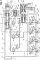
FIG. 1 is an overall block diagram to show a brake system applied with a check valve of the present embodiment; -
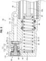
FIG. 2 is a cross-sectional view of a hydraulic pressure generator provided in the brake system of the present embodiment, showing main parts thereof; -
FIG. 3 is a perspective view of a check valve of the present embodiment, when attached to a base body of a slave cylinder; -
FIG. 4 is an exploded perspective view of the check valve of the present embodiment; -
FIG. 5 is a perspective view of the check valve of the present embodiment; -
FIG. 6 is a side view of the check valve of the present embodiment, to show a retainer in cross section; -
FIG. 7 is an enlarged vertical cross-sectional view of the check valve of the present embodiment; -
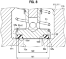
FIG. 8 is cross-sectional view of the check valve of the present embodiment, to show a relationship between a sealing member and an end of a spring, which are mounted to a plug; -
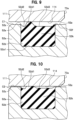
FIG. 9 is an enlarged cross-sectional view of the check valve of the present embodiment, to show the sealing member when assembled; -
FIG. 10 is an enlarged cross-sectional view of the check valve of the present embodiment, to show the sealing member when fluid pressure is low; -
FIG. 11 is an enlarged cross-sectional view of the check valve of the present embodiment, to show the sealing member when fluid pressure is high; -
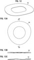
FIG. 12 is an enlarged perspective view of an elastic member to be assembled to the check valve of the present embodiment; -
FIG. 13A is an enlarged plan view of the elastic member to be assembled to the check valve of the present embodiment; -
FIG. 13B is an enlarged side view of the elastic member to be assembled to the check valve of the present embodiment; -
FIG. 13C is a cross-sectional view of the elastic member, taken along a line XIII-XIII inFIG. 13A ; -
FIG. 14A illustrates the check valve of the present embodiment when assembled to the base body; -
FIG. 14B illustrates the check valve of the present embodiment when the plug is open; and -
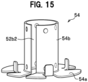
FIG. 15 is a perspective view of another form of the retainer of the check valve of the present embodiment. - Hereinafter, an embodiment for implementing the present invention is described in detail, with reference to the appended drawings. First, a description is given of a brake system provided with a check valve of the present embodiment. As shown in
FIG. 1 , a brake system A includes both a by-wire brake system to operate when a prime mover (engine, electric motor, and the like) is started, and a hydraulic brake system to operate when the prime mover is stopped. - The brake system A can be mounted on a hybrid vehicle that additionally uses a motor, an electric vehicle or a fuel cell vehicle that uses only the motor as a power source, and a vehicle that uses only an engine (internal engine) as a power source.
- The brake system A includes a hydraulic pressure generator 1 to generate brake hydraulic pressure in proportion to a stroke amount (operation amount) of a brake pedal P (brake operator) and support stabilization of vehicle behavior.
- The hydraulic pressure generator 1 includes a
base body 100 and amaster cylinder 10 to generate hydraulic pressure of brake fluid, as hydraulic fluid, in proportion to the stroke amount of the brake pedal P. In addition, the hydraulic pressure generator 1 includes, as component units, astroke simulator 40 to apply a pseudo operation reaction force to the brake pedal P, and aslave cylinder 20 to generate brake hydraulic pressure using amotor 24 as a drive source. Further, the hydraulic pressure generator 1 includes, as component units, a hydraulicpressure control unit 30 to control hydraulic pressure of brake fluid acting on wheel cylinders W of a wheel brake BR and support stabilization of vehicle behavior, areservoir tank 80, and anelectronic control unit 90. - The
base body 100 is a metal block mounted on a vehicle. Thebase body 100 is formed therein with threecylinder holes base body 100 has various parts, such as thereservoir tank 80 and themotor 24, attached thereto. - The first cylinder hole 11, the
second cylinder hole 21, and thethird cylinder hole 41 each have a bottomed cylindrical shape. The axes (not shown) of the cylinder holes 11, 21, 41 are aligned in parallel and in line. Ends of the cylinder holes 11, 21, 41 are open tosurfaces base body 100. - The
master cylinder 10 is a tandem piston type having twofirst pistons 12a and 12b. The first cylinder hole 11 accommodates therein twocoil springs - The
coil spring 17a is arranged in a bottom-side pressure chamber 16a formed between abottom surface 11a in the first cylinder hole 11 and the bottom-side first piston 12a. Thecoil spring 17a pushes the first piston 12a, which has been moved toward thebottom surface 11a, back toward anopening 11b. Thecoil spring 17b is arranged in an opening-side pressure chamber 16b formed between the first piston 12a and the opening-sidefirst piston 12b. Thecoil spring 17b pushes thefirst piston 12b, which has been moved toward thebottom surface 11a, back toward theopening 11b. - A rod P1 of the brake pedal P is inserted into the first cylinder hole 11 and connected to the
first piston 12b. Both thefirst pistons 12a and 12b receive pedal pressure of the brake pedal P and slide in the first cylinder hole 11, to pressurize brake fluid in the bottom-side pressure chamber 16a and the opening-side pressure chamber 16b. - The
reservoir tank 80 is a container to store brake fluid, and is attached to asurface 101e of thebase body 100. Two fluid supply portions projecting from thereservoir tank 80 are inserted into tworeservoir union ports surface 101e of thebase body 100. This allows brake fluid to be replenished in the bottom-side pressure chamber 16a and the opening-side pressure chamber 16b. - The
stroke simulator 40 includes athird piston 42 inserted into thethird cylinder hole 41, alid member 44 to close anopening 41b of thethird cylinder hole 41, and twocoil springs third piston 42 and thelid member 44. - A bottom surface 41a of the
third cylinder hole 41 and thethird piston 42 defines apressure chamber 45 therebetween. Thepressure chamber 45 leads to the opening-side pressure chamber 16b of the first cylinder hole 11 via the branchhydraulic path 3 and the second mainhydraulic path 2b, which are to be described below. In thestroke simulator 40, brake fluid pressure generated in the opening-side pressure chamber 16b of themaster cylinder 10 moves thethird piston 42 against a biasing force of thecoil springs - The
slave cylinder 20 is of a single piston type and includes asecond piston 22 inserted in thesecond cylinder hole 21, acoil spring 23 housed in thesecond cylinder hole 21, themotor 24, and adrive transmission unit 25. - A
bottom surface 21a in thesecond cylinder hole 21 and thesecond piston 22 defines a pressure chamber (hydraulic pressure chamber) 26 therebetween. Thepressure chamber 26 houses thecoil spring 23 therein. Thecoil spring 23 pushes thesecond piston 22, which has been moved toward thebottom surface 21a, back toward anopening 21b. - The
motor 24 is an electric servomotor to be driven and controlled by theelectronic control unit 90. Themotor 24 is attached to aflange 103 of thebase body 100. Anoutput shaft 24a of themotor 24 projects to the other side of theflange 103 through aninsertion hole 103c formed in theflange 103. Theoutput shaft 24a has a drivingpulley 24b attached thereto. - The
drive transmission unit 25 is a mechanism to convert a rotational driving force of theoutput shaft 24a of themotor 24 into a linear axial force. Thedrive transmission unit 25 includes arod 25a, acylindrical nut member 25b surrounding therod 25a, a drivenpulley 25c provided all around thenut member 25b, anendless belt 25d wound around the drivenpulley 25c and the drivingpulley 24b, and acover member 25e. - The
rod 25a is inserted into thesecond cylinder hole 21 through theopening 21b of thesecond cylinder hole 21, and an end of therod 25a abuts on thesecond piston 22. A ball screw mechanism is provided between an outer peripheral surface of therod 25a and an inner peripheral surface of thenut member 25b. - When the
output shaft 24a is rotated, a rotational driving force thereof is inputted to thenut member 25b via the drivingpulley 24b, thebelt 25d, and the drivenpulley 25c. Then, the ball screw mechanism between thenut member 25b and therod 25a applies a linear axial force to therod 25a, and therod 25a is moved back and forth in the axial direction. When therod 25a is moved toward thebottom surface 21a, thesecond piston 22 receives the input from therod 25a and slides in thesecond cylinder hole 21 to pressurize the brake fluid in thepressure chamber 26. - Next, a description is given of the hydraulic paths formed in the
base body 100. As shown inFIG. 1 , the two mainhydraulic paths master cylinder 10. The first mainhydraulic path 2a is connected to the two wheel brakes BR from the bottom-side pressure chamber 16a of themaster cylinder 10 via the hydraulicpressure control unit 30. The second mainhydraulic path 2b is connected to the other two wheel brakes BR from the opening-side pressure chamber 16b of themaster cylinder 10 via the hydraulicpressure control unit 30. - The branch
hydraulic path 3 is a hydraulic path from thepressure chamber 45 of thestroke simulator 40 to the second mainhydraulic path 2b. The branchhydraulic path 3 is provided with a normally-closedsolenoid valve 8. The normally-closedsolenoid valve 8 opens and closes the branchhydraulic path 3. - The two
communication paths second cylinder hole 21 of theslave cylinder 20. Both thecommunication paths fluid path 4a, and lead to thesecond cylinder hole 21. Thefirst communication path 5a is a flow path from thepressure chamber 26 in thesecond cylinder hole 21 to the first mainhydraulic path 2a, and the secondcontinuous path 5b is a flow path from thepressure chamber 26 to the second mainhydraulic path 2b. - A
first switching valve 63, which is a three-way valve, is provided at a connection point between the first mainhydraulic path 2a and thefirst communication path 5a. Thefirst switching valve 63 is a solenoid valve with two positions and three ports. When thefirst switching valve 63 is in a first position shown inFIG. 1 , an upstream side (closer to the master cylinder 10) and a downstream side (closer to the wheel brakes BR) of the first mainhydraulic path 2a communicate with each other, while the first mainhydraulic path 2a is shut off from thefirst communication path 5a. When thefirst switching valve 63 is in a second position, the upstream side of the first mainhydraulic path 2a is shut off from the downstream side, while thefirst communication path 5a and the downstream side of the first mainhydraulic path 2a communicate with each other. - A
second switching valve 64, which is a three-way valve, is provided at a connection point between the second mainhydraulic path 2b and thesecond communication path 5b. Thesecond switching valve 64 is a solenoid valve with two position and three ports. When thesecond switching valve 64 is in a first position shown inFIG. 1 , an upstream side (closer to the master cylinder 10) and a downstream side (closer to the wheel brakes BR) of the second mainhydraulic path 2b communicate with each other, while the second mainhydraulic path 2b is shut off from thesecond communication path 5b. When thesecond switching valve 64 is in a second position, the upstream side of the second mainhydraulic path 2b is shut off from the downstream side, while thesecond communication path 5b and the downstream side of the second mainhydraulic path 2b communicate with each other. - The
first communication path 5a is provided with afirst shutoff valve 61. Thefirst shutoff valve 61 is a normally-open solenoid valve. When thefirst shutoff valve 61 is closed while energized, thefirst communication path 5a is shut off in thefirst shutoff valve 61. Thesecond communication path 5b is provided with asecond shutoff valve 62. Thesecond shutoff valve 62 is a normally-open solenoid valve. When thesecond shutoff valve 62 is closed while energized, thesecond communication path 5b is shut off in thesecond shutoff valve 62. - Two
pressure sensors 6 and 7 detect magnitude of brake fluid pressure, and information obtained by both thepressure sensors 6 and 7 is outputted to theelectronic control unit 90. Thefirst pressure sensor 6 is arranged on an upstream side of thefirst switching valve 63 and detects brake fluid pressure generated in themaster cylinder 10. The second pressure sensor 7 is arranged on a downstream side of thesecond switching valve 64 and, when the twocommunication paths hydraulic paths slave cylinder 20. - The slave
cylinder supply path 73 is a flow path from thereservoir tank 80 to theslave cylinder 20. The slavecylinder supply path 73 is connected to the common hydraulic path 4 via abranch supply path 73a. Thebranch supply path 73a is provided with acheck valve 50 to allow brake fluid to flow only in a direction from thereservoir tank 80 to the common hydraulic path 4 (or to the slave cylinder 20). As thecheck valve 50 is provided in thebranch supply path 73a, thecheck valve 50 suitably prevents hydraulic pressure generated in theslave cylinder 20 from being transmitted toward thereservoir tank 80. - Normally, the brake fluid is replenished from the
reservoir tank 80 to theslave cylinder 20 through the slavecylinder supply path 73. Alternatively, at a time of fluid aspiration control to be described below, brake fluid is aspirated from thereservoir tank 80 to theslave cylinder 20 through a supply path including the slavecylinder supply path 73, thebranch supply path 73a, thecheck valve 50, the dischargingfluid path 4a, and adischarge port 27. - The
return fluid path 74 is a flow path from the hydraulicpressure control unit 30 to thereservoir tank 80. The brake fluid released from the wheel cylinders W flows into thereturn fluid path 74 via the hydraulicpressure control unit 30. The brake fluid released into thereturn fluid path 74 is returned to thereservoir tank 80 through thereturn fluid path 74. - The hydraulic
pressure control unit 30 suitably controls hydraulic pressure of brake fluid acting on the wheel cylinders W of the wheel brakes BR. The hydraulicpressure control unit 30 has a configuration capable of executing anti-lock brake control. The wheel cylinders Ware respectively connected tooutlet ports 301 of thebase body 100 via pipes. - The hydraulic
pressure control unit 30 increases, holds, or decreases hydraulic pressure acting on the wheel cylinders W (hereinbelow, referred to as "wheel cylinder pressure"). The hydraulicpressure control unit 30 includes aninlet valve 31, anoutlet valve 32, and acheck valve 33. - The
inlet valve 31 is arranged for each of two hydraulic paths from the first mainhydraulic path 2a to the two wheel brakes BR, and for each of two hydraulic paths from the second mainhydraulic path 2b to the two wheel brakes BR. Theinlet valve 31 is a normally-open proportional solenoid valve (linear solenoid valve), and valve opening pressure of theinlet valve 31 is adjustable in proportion to a current value flowing through a coil of theinlet valve 31. Theinlet valve 31 is normally open to allow hydraulic pressure to be applied from theslave cylinder 20 to the wheel cylinder W. Theinlet valve 31 closes under the control of theelectronic control unit 90 when the wheels are about to be locked, to shut off the brake fluid pressure to be applied to the wheel cylinder W. - The
outlet valve 32 is a normally-closed solenoid valve arranged between the wheel cylinder W and thereturn fluid path 74. Theoutlet valve 32 is normally closed, but opened under the control of theelectronic control unit 90 when the wheels are about to be locked. - The
check valve 33 is connected in parallel to theinlet valve 31. Thecheck valve 33 is a valve to allow brake fluid to flow only in a direction from the wheel cylinder W to the slave cylinder 20 (or to the master cylinder 10). Therefore, thecheck valve 33 allows brake fluid to flow in a direction from the wheel cylinder W to theslave cylinder 20, even when theinlet valve 31 is closed. - The
electronic control unit 90 includes ahousing 91 as a box made of resin, and a control board (not shown) housed in thehousing 91. Thebase body 100 is formed with a mounting surface for theelectronic control unit 90. Theelectronic control unit 90 controls operation of themotor 24 and opening/closing of the valves, based on information obtained from various sensors, such as both thepressure sensors 6, 7 and a stroke sensor (not shown), and a program stored in advance. - In addition, the
electronic control unit 90 has a function of executing fluid aspiration control. The fluid aspiration control controls positively aspirating the brake fluid into theslave cylinder 20 from thereservoir tank 80 via the slave cylinder supply path 73 (check valve 50). This secures an amount of brake fluid in theslave cylinder 20. The fluid aspiration control is executed when brake fluid is desired to be secured for pressurizing by theslave cylinder 20 up to a high hydraulic pressure level, for example. The fluid aspiration control is also executed in a case where the brake fluid is secured in advance in preparation for subsequent pressurization, with fluid pressure generated by theslave cylinder 20 having reached a level (normal level) required by a driver. - Next, a description is briefly given of operation of the brake system A. In the brake system A in
FIG. 1 , both the switchingvalves hydraulic path 2a to communicate with thefirst communication path 5a, and causes the downstream side of the second mainhydraulic path 2b to communicate with thesecond communication path 5b. Then, themaster cylinder 10 is shut off from the wheel cylinders W, while theslave cylinder 20 and the wheel cylinders W communicate with each other. - In addition, the normally-closed
solenoid valve 8 in the branchhydraulic path 3 is opened, when the system is activated. This causes hydraulic pressure generated in themaster cylinder 10 by operation of the brake pedal P to be transmitted to thestroke simulator 40, instead of being transmitted to the wheel cylinders W. When hydraulic pressure in thepressure chamber 45 of thestroke simulator 40 increases, thethird piston 42 is moved toward thelid member 44 against biasing forces of thecoil springs - When the stroke sensor (not shown) detects that the brake pedal P has been stepped, the
electronic control unit 90 drives themotor 24 of theslave cylinder 20, to move thesecond piston 22 of theslave cylinder 20 toward thebottom surface 21a. This causes brake fluid in thepressure chamber 26 to be pressurized. Theelectronic control unit 90 compares hydraulic pressure generated by the slave cylinder 20 (hydraulic pressure detected by the second pressure sensor 7) with required hydraulic pressure corresponding to the operation amount of the brake pedal P, and controls the rotation speed of themotor 24 and the like, based on a comparison result. In this way, the brake system A increases hydraulic pressure in proportion to the operation amount of the brake pedal P. Then, hydraulic pressure generated by theslave cylinder 20 is inputted to the hydraulicpressure control unit 30. - When the stepping of the brake pedal P is released, the
motor 24 of theslave cylinder 20 is reversely driven by theelectronic control unit 90, to return thesecond piston 22 toward themotor 24 by thecoil spring 23. This causes pressure inside thepressure chamber 26 to be decreased. - In the hydraulic
pressure control unit 30, opening/closing of theinlet valve 31 and theoutlet valve 32 is controlled by theelectronic control unit 90, to adjust wheel cylinder pressure of the wheel cylinder W. In a normal state with theinlet valve 31 opened and theoutlet valve 32 closed, for example, hydraulic pressure generated in theslave cylinder 20 is directly transmitted to the wheel cylinder W, when the brake pedal P has been stepped, to increase wheel cylinder pressure. In a state with theinlet valve 31 closed and theoutlet valve 32 opened, the brake fluid flows out from the wheel cylinder W toward thereturn fluid path 74, to decrease wheel cylinder pressure. In a state with both theinlet valve 31 and theoutlet valve 32 closed, the wheel cylinder pressure is maintained. - Note that when the
slave cylinder 20 is not in operation (when the ignition is turned off or power is not available, for example,), thefirst switching valve 63, thesecond switching valve 64, and the normally-closedsolenoid valve 8 each return to an initial state. This causes the upstream sides of both the mainhydraulic paths master cylinder 10 is transmitted to the wheel cylinders W via the hydraulicpressure control unit 30. - Next, the check valve 50 (see
FIG. 1 ) is described. Thecheck valve 50 is arranged in vicinity to thedischarge port 27 of theslave cylinder 20, as shown inFIG. 2 . In particular, thecheck valve 50 is arranged at an end portion of thebase body 100 where thesecond cylinder hole 21 is formed. - The
check valve 50 is installed in a steppedaccommodation chamber 111 having a circular cross section to communicate with thebranch supply path 73a. Theaccommodation chamber 111 is open to an end surface of thebase body 100. Theaccommodation chamber 111 includes a large-diameter portion 112 having a large diameter, as a first accommodation chamber, and a small-diameter portion 113 having a smaller diameter than the large-diameter portion 112, as a second accommodation chamber. The small-diameter portion 113 is formed to have a larger diameter, with a steppedportion 113a as a boundary. The small-diameter portion 113 is formed with aflat seat surface 114. Theseat surface 114 is open, in a radially center thereof, to thebranch supply path 73a. Thebranch supply path 73a communicates with the slavecylinder supply path 73. - The
check valve 50 includes acap 51, aplug 52, aspring 53, and aretainer 54. As shown inFIG. 3 , thecheck valve 50 is configured wholly as a unit (multiple-part combined product). Accordingly, thecheck valve 50 is assembled in theaccommodation chamber 111 of thebase body 110 as a multiple-part combined product. - As shown in
FIG. 2 , thecap 51 is accommodated in the large-diameter portion 112 of theaccommodation chamber 111, and prevented by aC ring 115, attached to an inner surface closer to an opening of thebase body 100, from coming out of theaccommodation chamber 111. As shown inFIG. 4 , thecap 51 includes a disk-shapedcap base 51a and a columnarfirst extension 51b extending from thecap base 51a toward theplug 52. - The
cap base 51a is formed, in an outer peripheral surface thereof, with a peripheral groove 51a1. The peripheral groove 51a1 has an O-ring 55 mounted thereon to work as a sealing member. The O-ring 55 closely contacts an inner peripheral surface of theaccommodation chamber 111, to seal theaccommodation chamber 111 in a liquid-tight manner. - The
first extension 51b is integrally provided with thecap base 51a. Thefirst extension 51b has a base end portion 51b1, connected to thecap base 51a, formed to have a larger diameter than the rest thereof. The base end portion 51b1 is formed, in an outer peripheral surface thereof, with a peripheral groove 51b2 as a groove. As shown inFIG. 7 , majority of thefirst extension 51b is positioned inside theretainer 54. - As shown in
FIG. 2 , theplug 52 is a member accommodated in the small-diameter portion 113 of theaccommodating chamber 111, and seated on or separated from the seat surface 114 (seeFIGS. 14A and 14B ). As shown inFIGS. 4 to 7 , theplug 52 includes a disk-shapedplug base 52a and a cylindricalsecond extension 52b extending from theplug base 52a toward thecap 51. - The
plug base 52a has aflat seating surface 52z facing theseat surface 114 of theaccommodation chamber 111. Theseating surface 52z is formed therein with an annular groove 52a1 concentric with theplug base 52a. The annular groove 52a1 is mounted therein with anannular sealing member 52d to seal a gap between theseating surface 52z of theplug base 52a and theseating surface 114 of the accommodation chamber 111 (FIG. 8 ). The sealingmember 52d seals theaccommodation chamber 111, acted on by hydraulic pressure of brake fluid in the flow path, from the branch supply path (at atmospheric pressure) 73a not acted on by hydraulic pressure of brake fluid. Theseating surface 52z of theplug base 52a and theseat surface 114 of theaccommodation chamber 111 are formed flat so as to closely contact with each other. The sealingmember 52d is made of rubber and is fixed in the annular groove 52a1 by vulcanization adhesion or the like. - In the present embodiment, one side in the flow path, connected to the
pressure chambers reservoir tank 80, is not acted on by hydraulic pressure of brake fluid. - As shown in
FIG. 9 , the sealingmember 52d includes abase portion 52k, an annular ridge portion 52d1, an annular radially outer portion 52d2, and an annular radially inner portion 52d3. Thebase portion 52k is a portion fixed into the annular groove 52a1. The ridge portion 52d1 protrudes, in a rounded mountain shape in cross section, from thebase portion 52k toward theseat surface 114 of theaccommodation chamber 111. The ridge portion 52d1 protrudes with respect to theseating surface 52z of theplug base 52a and works as a sealing point to abut on theseat surface 114 to close thebranch supply path 73a. - In addition, the ridge portion 52d1 is positioned on a surface, to face the
seat surface 114, of the sealingmember 52d, so as to be radially skewed to a region of the surface, acted on by hydraulic pressure of brake fluid in the hydraulic path, with respect to another region of the surface, not acted on by hydraulic pressure of the brake fluid. That is, the ridge portion 52d1 is skewed in the radial direction of the sealingmember 52d to the radially outer portion 52d2. This secures a large area of the radially inner portion 52d3. - In an initial state of the
check valve 50 installed (assembled) in theaccommodation chamber 111, a tip end portion of the ridge portion 52d1 abuts on theseat surface 114 of theaccommodation chamber 111 by a biasing force of thespring 53 of thecheck valve 50, as shown inFIG. 9 . This causes theseating surface 52z of theplug base 52a not to closely contact theseat surface 114 of theaccommodation chamber 111, to define a clearance C1 therebetween. Note that a certain level of surface pressure is applied in the initial state to the ridge portion 52d1I, to allow for sealing brake fluid pressure in atmospheric pressure or extremely low pressure. - The radially outer portion 52d2 has a substantially U-shape in cross section, and is recessed from the
seating surface 52z of theplug base 52a toward a direction away from theseat surface 114 of the accommodation chamber 111 (toward a bottom of the annular groove 52a1). The radially outer portion 52d2 is adjacent to a radially outer side of the ridge portion 52d1, and an inner end thereof is continuous to the radially outer side of the ridge portion 52d1. An outer end of the radially outer portion 52d2 is joined to anouter opening edge 52e of the annular groove 52a1. The radially outer portion 52d2 flexibly extends inward in the radial direction when the radially inner portion 52d3 receives brake fluid pressure and is deformed inward in the radial direction, as will be described below. - The radially inner portion 52d3 has a substantially inverted trapezoidal shape in cross section, and is recessed from the
seating surface 52z of theplug base 52a toward a direction being away from theseat surface 114 of the accommodation chamber 111 (toward a bottom in the annular groove 52a1). The radially inner portion 52d3 is adjacent to a radially inner side of the ridge portion 52d1, and an outer end thereof is continuous to the radially inner side of the ridge portion 52d1. An inner end of the radially inner portion 52d3 is joined to aninner opening edge 52f of the annular groove 52a1. - The radially inner portion 52d3 is a portion corresponding to a deformed portion to be deformed by brake fluid pressure. The radially inner portion 52d3 is deformed radially inward by increased brake fluid pressure, together with the ridge portion 52d1, and bulging toward, and abutting on, the seat surface 114 (see
FIG. 11 ). - Next, a description is given of a change in a cross-sectional shape of the sealing
member 52d, with reference toFIGS. 10 and11 .FIG. 10 shows the sealingmember 52d when fluid pressure is low. When fluid pressure is low means when a relatively low brake fluid pressure acts on theplug base 52a through theaccommodation chamber 111, such as when the brake pedal P is pedaled relatively lightly or during initial operation of the brake pedal P. - When fluid pressure is low, the tip of the ridge portion 52d1 abuts on the
seat surface 114 of theaccommodating chamber 111 while being given in to fluid pressure, to define a clearance C2 between theseating surface 52z of theplug base 52a and theseat surface 114 of theaccommodating chamber 111, which is smaller than the clearance C1 in the above-described initial state. Note that predetermined surface pressure is applied to the ridge portion 52d1, to allow for sealing brake fluid at low pressure. -
FIG. 11 shows the sealingmember 52d when fluid pressure is high. When fluid pressure is high means when brake fluid pressure, higher than that when the fluid pressure is low, is acting on theplug base 52a through theaccommodating chamber 111, such as when the brake pedal P is kept pedaled hard. - When the fluid pressure is high, the
seating surface 52z of theplug base 52a abuts on, and closely contacts, theseat surface 114 of theaccommodation chamber 111. When fluid pressure is high, the radially inner portion 52d3 is then deformed by brake fluid pressure, larger than that when fluid pressure is low, toward a radially inner location at atmospheric pressure (toward thebranch supply path 73a). This causes the radially inner portion 52d3 to bulge toward theseat surface 114 so that the entire surface to face theseat surface 114 closely contacts theseat surface 114. At this time, a predetermined surface pressure is applied to the radially inner portion 52d3, to allow for sealing the brake fluid when the fluid pressure is high. Note that the radially outer portion 52d2 flexibly extends inward in the radial direction when the fluid pressure is high, to allow the radially inner portion 52d3 to be smoothly deformed. - As shown in
FIGS. 4 ,6 and7 , theplug base 52a is formed at an edge thereof with a step 52a2 continuous in the circumferential direction. The step 52a2 has an end of thespring 53 engaged therewith. The step 52a2 works to receive the biasing force inputted by thespring 53. - As shown in
FIG. 8 , a lock diameter M1 of thespring 53 being locked to the step 52a2 is larger than an abut diameter M2 of the ridge portion 52d1 abutting on theseat surface 114. That is, the sealing point of the sealingmember 52d with respect to theflat seat surface 114 is located radially inner than an abutting point of thespring 53 abutting on theplug base 52a. - The
second extension 52b is integrally provided with theplug base 52a. As shown inFIG. 7 , thesecond extension 52b is slidably mounted in an axial direction onto an outer surface of thefirst extension 51b of thecap 51. Thesecond extension 52b is formed, on an outer peripheral surface of a front end thereof, with aflange 52c bulging in the radial direction thereof. An outer surface of theflange 52c is tapered toward a tip end of theflange 52c. Additionally, theflange 52c includes an annular surface 52c1 to face theplug base 52a. - The
second extension 52b is formed with one or more circular through-holes 52b1 as a flow-through portion. The four through-holes 52b1 (three holes are shown inFIG. 7 ) are provided in total in a circumferential direction of thesecond extension 52b at predetermined intervals. The through-holes 52b1 are arranged at positions not to be closed by thefirst extension 51b of thecap 51 when theplug 52 is slid. - The
spring 53 is interposed between thecap 51 and theplug 52 with a biasing force. Thespring 53 is compressively provided between aretainer base 54a of theretainer 54 attached to thecap 51 and the step 52a2 of theplug base 52a. An outer diameter of thespring 53 is substantially the same as an outer diameter of theplug base 52a. - The
retainer 54 has a substantially cylindrical shape. Theretainer 54 includes theretainer base 54a in a substantially circular thin plate shape, and acylindrical wall 54b extending from theretainer base 54a toward theplug 52. - The
retainer base 54a works to receive an end of thespring 53. Theretainer base 54a is integrally formed with protrusions 54a1 projecting toward theplug 52. The protrusions 54a1 are formed by making notches in theretainer base 54a and raising the notches toward theplug 52. The four protrusions 54a1 are provided in total in the circumferential direction of theretainer base 54a at predetermined intervals. The protrusions 54a1 are arranged radially inside thespring 53 so as to face thespring 53 with a slight gap, to prevent thespring 53 from being moved in the radial direction. Note that the protrusions 54a1 may be configured to abut on thespring 53 from radially inside of thespring 53. - The
cylindrical wall 54b extends toward theplug 52, and is formed to a size of a front end thereof being located radially outside theflange 52c of thesecond extension 52b (to overlap), as shown inFIGS. 6 and7 . Here, assuming that a clearance between the outer surface of thefirst extension 51b of thecap 51 and the inner surface of thesecond extension 52b of theplug 52 is CL1, and a clearance between the outer surface of thesecond extension 52b and the inner surface of thecylindrical wall 54b is CL2, as shown inFIG. 7 , there is a relationship of CL1 being smaller than CL2 (CL1 < CL2). This relationship also holds true, when tolerance of said portions is taken into consideration, in a relationship between the maximum value (maximum allowable dimension) and the minimum value (minimum allowable dimension). That is, even when the clearance CL1 is defined with the outer surface of thefirst extension 51b sized to the minimum allowable dimension and the inner surface of thesecond extension 52b sized to the maximum allowable dimension, and the clearance CL2 is defined with the outer surface of thesecond extension 52b sized to the maximum allowable dimension and the inner surface of thecylindrical wall 54b sized to the minimum allowable dimension, the relationship of CL1 being smaller than CL2 (CL1 < CL2) holds true. - The clearance CL1 allows the
first extension 51b and thesecond extension 52b to slidably contact with each other with a sliding allowance N1 in the axial direction. The sliding allowance N1 is increased by theplug 52 being moved toward thecap 51 against the biasing force of thespring 53. - The
cylindrical wall 54b is formed, at a front end thereof, with first protrusions 54b1. The first protrusions 54b1 are each a protrusion projecting inward in the radial direction of thecylindrical wall 54b, and the four first protrusions 54b1 are formed in total in a circumferential direction of thecylindrical wall 54b at equal angular intervals of 90 degrees about an axis of theretainer 54. The first protrusions 54b1 are positioned to axially interfere with (to axially oppose) the annular surface 52c1 of theflange 52c of thesecond extension 52b. This causes the first protrusions 54b1 to be locked to the annular surface 52c1 of theflange 52c of thesecond extension 52b, with the above-described clearance CL2, as shown inFIG. 7 . - In addition, the
cylindrical wall 54b is formed, at positions closer to the protrusions 54a1, with second protrusions 54b4. The second protrusions 54b4 are each a protrusion projecting inward in the radial direction of thecylindrical wall 54b, and the four second protrusions 54b4 are formed in total in the circumferential direction of thecylindrical wall 54b at equal angular intervals of 90 degrees about the axis of theretainer 54. The second protrusions 54b4 are engaged with the peripheral groove 51b2 of the base end portion 51b1 of thefirst extension 51b, with a predetermined amount of movement allowed in the axial direction. - Further, the
cylindrical wall 54b is formed therein with a slit 54b2 extending in the axial direction. The slit 54b2 extends from thecylindrical wall 54b to theretainer base 54a, entirely through thecylindrical wall 54b and theretainer base 54a. The slit 54b2 allows theretainer 54 to be expanded and contracted in the radial direction. When theretainer 54 is assembled to thecap 51, expansion and contraction thereof due to the slit 54b2 is used to engage the second protrusions 54b4 with the peripheral groove 51b2 of the base end portion 51b1 of thefirst extension portion 51b. - Furthermore, the
cylindrical wall 54b is formed with one or more circular through-holes 54b3 as a flow-through portion. In the present embodiment, the two through-holes 54b3a are provided in total at positions to face in the radial direction of thecylindrical wall 54b, away from those where the slit 54b2 is formed. Brake fluid can flow through the through-holes 54b3. - A waved
washer 56 as an elastic member is interposed between thecap 51 and theretainer base 54a. As shown inFIGS. 12, 13A, 13B, 13C , the wavedwasher 56 has curved abutting points on surfaces thereof, to have a predetermined spring constant. The wavedwasher 56, when interposed between thecap 51 and theretainer base 54a, biases theretainer base 54a by a spring force toward the plug 52 (spring 53). The spring constant of the wavedwasher 56 is set to be larger than the spring constant of thespring 53. - A biasing force of the waved
washer 56 causes theretainer base 54a to constantly abut on a flat stepped portion 116 formed at a boundary between the large-diameter portion 112 and the small-diameter portion 113 of theaccommodation chamber 111, as shown inFIG. 14A . This allows for determining an installed length of thespring 53 with reference to the stepped portion 116. That is, the installed length of thespring 53 is determined constant, without consideration of dimensional tolerance of thecap 51, dimensional tolerance of theC ring 115, and dimensional tolerance of a fixinggroove 115a for fixing theC ring 115. Note that the spring constant of the wavedwasher 56 is larger than the spring constant of thespring 53, as described above. This causes theretainer base 54a to suitably remain abutting on the stepped portion 116, even with a reaction force of thespring 53 acting on theretainer base 54a when theplug 52 has been separated from theseat surface 114, as shown inFIG. 14B . - Next, a description is given of operation of the
check valve 50 during fluid aspiration control. Note that thepressure chamber 26 of theslave cylinder 20 secures an amount of brake fluid required for normal (regular) braking control, except for special braking such as sudden braking. - The fluid aspiration control causes the
first shutoff valve 61 and thesecond shutoff valve 62 to be closed, and thesecond piston 22 to be driven in a depressurizing direction (return direction) to decrease pressure. Then, thepressure chamber 26 is depressurized to have negative pressure, while hydraulic pressure in the wheel cylinder W is held. This causes brake fluid to be aspirated from thereservoir tank 80 to thepressure chamber 26 through the supply path including the slavecylinder supply path 73, thebranch supply path 73a, thecheck valve 50, the dischargingfluid path 4a, and thedischarge port 27. At this time, thecheck valve 50 has theplug base 52a separated from theseat surface 114 against the biasing force of thespring 53, due to negative pressure in thepressure chamber 26, as shown inFIG. 14B . This allows the brake fluid to flow into thepressure chamber 26 of theslave cylinder 20 through thecheck valve 50. - When the fluid aspiration control has been completed, the
first shutoff valve 61 and thesecond shutoff valve 62 are opened to drive thesecond piston 22 in a pressurizing direction (direction approaching thebottom surface 21a). This causes brake fluid aspirated into thepressure chamber 26 to be pressurized. In accordance with completion of the fluid aspiration control, thecheck valve 50 has theplug base 52a seated on theseat surface 114 by the biasing force of thespring 53. Additionally, brake fluid aspirated into thepressure chamber 26 is pressurized to press theplug base 52a against theseat surface 114. This causes thebranch supply path 73a to be blocked by theplug 52, to prevent brake fluid from flowing out of theslave cylinder 20 toward thereservoir tank 80. - The
check valve 50 of the present embodiment as described above has thecap 51, theplug 52, and thespring 53 combined by the agency of theretainer 54, as a combined product. Therefore, there is no need to assemble the cap, the plug, and the spring in thebase body 100, as in conventional cases. This reduces manufacturing costs and suitably prevents grit and dust from entering the assembly. - In addition, the
check valve 50 being assembled as a combined product allows for reliably preventing theplug 52 andspring 53 from falling, to have no chance of the product being assembled with these failures. Thecheck valve 50 being a combined product also facilitates part replacement of thecheck valve 50. - Further, the
retainer 54 is locked to theplug 52, with the first protrusion 54b1 of thecylindrical wall 54b of theretainer 54 locked to the annular surface 52c1 of theflange 52c of thesecond extension 52b of theplug 52. Accordingly, the locking structure is simple to facilitate combining thecheck valve 50. - Still further, the protrusion 54a1 of the
retainer base 54a of theretainer 54 positions an end of thespring 53 on theretainer base 54a, to have less chance of theplug 52 having an unbalanced load when slid with respect to thecap 51. Accordingly, sliding resistance is reduced and surface pressure of thespring 53 is equalized with respect to theplug 52, to improve seating performance of theplug 52. - Still further, the second protrusion 54b4 of the
retainer 54 engaging with the peripheral groove 51b2 of thecap 51 allows theretainer 54 to be attached to thecap 51. Therefore, the attaching structure is simple to facilitate combining thecheck valve 50. - Still further, the clearance CL1 between the outer surface of the
first extension 51b and the inner surface of thesecond extension 52b and the clearance CL2 between the outer surface of thesecond extension 52b and the inner surface of thecylindrical wall 54b have the relationship of CL1 being smaller than CL2 (CL1 < CL2). This allows for securing a clearance of the inner surface of thecylindrical wall 54b of theretainer 54 not contacting the outer surface of thesecond extension 52b, when thesecond extension 52b is slid with respect to thefirst extension 51b. Accordingly, sliding resistance is reduced to improve response of opening/closing the flow path by theplug 52. - Still further, the
second extension 52b and thecylindrical wall 54b are respectively formed with the through-holes 52b1 and 54b3 to allow brake fluid to flow through the through-holes 52b1 and 54b3, to prevent sliding lock due to fluid tightness. - Still further, the
first extension 51b and thesecond extension 52b are in sliding contact with each other, with the sliding allowance N1 extending in the axial direction thereof, to implement smooth sliding between thefirst extension 51b and thesecond extension 52b. Additionally, an increase in sliding amount also increases the sliding allowance, to effect a stable stroke of theplug 52 with respect to thecap 51. - Still further, the
cap 51 is fixed to the large-diameter portion 112, with thecap base 51a abutting on the steppedportion 113a formed at the boundary between the large-diameter portion 112 and the small-diameter portion 113. Accordingly, thecap 51 is prevented from being moved due to negative or positive pressure in theslave cylinder 20 connected to the dischargingfluid path 4a. This prevents variation in stroke performance of theplug 52, to stabilize an installed load of theplug 52. - Still further, the waved
washer 56 has a spring constant greater than that of thespring 53. This allows thecap base 51a to remain abutted on the steppedportion 113a, without being affected by expansion and contraction of thespring 53, to suitably prevent thecap 51 from being moved. Accordingly, variation in stroke performance of theplug 52 is prevented to further stabilize the installed load of theplug 52. - Still further, one end of the
spring 53 is positioned on theretainer base 54a by the protrusion 54a1 of theretainer base 54a, to have less chance of theplug 52 having an unbalanced load when slid with respect to thecap 51. Accordingly, the sliding resistance is reduced and the surface pressure of thespring 53 with respect to theplug 52 is equalized, to improve seating performance of theplug 52. - Still further, the
flat seating surface 52z of theplug 52 is seated on theflat seat surface 114 in the flow path and the sealingmember 52d is provided on theseating surface 52z, so that what is executed is to seal a gap between two flat surfaces, to further improve sealing performance and durability. Sealing a gap between two flat surfaces also allows for increasing a diameter of the flow path while ensuring sealing performance. Accordingly, thecheck valve 50 can be used in a large flow path. - Still further, the sealing point of the sealing
member 52d is located radially inner than the abutting point of thespring 53. This allows theplug 52 to be pressed toward theseat surface 114 over a wider area. This secures a sufficient level of theplug 52 being parallel with respect to theflat seat surface 114 in the flow path, to also improve adhesiveness of the sealingmember 52d with respect to theseat surface 114. Accordingly, sealing performance of theplug 52 is improved with respect to theseat surface 114. - Still further, the sealing
member 52d has the protrusion 52d1 abutted on theseat surface 114 for sealing, when hydraulic pressure of brake fluid is low. In contrast, the radially inner portion 52d3 is deformed from one side in the hydraulic path, acted on by hydraulic pressure of brake fluid, toward the other side in the hydraulic path, not acted on by hydraulic pressure of brake fluid, when hydraulic pressure of brake fluid is medium or high, to seal one from the other. This implements a two-phased sealing correlating to hydraulic pressure of brake fluid. - Still further, the ridge portion 52d1 is positioned so as to be skewed to one part of the surface, to face the
seat surface 114, of the sealingmember 52d, acted on by hydraulic pressure of brake fluid, with respect to the other part of the surface, not acted on by hydraulic pressure of brake fluid. This causes an area of said the other part of the surface, to face theseat surface 114, of the sealingmember 52d, not acted on by hydraulic pressure of brake fluid, to become wide. Accordingly, the radially inner portion 52d3 is suitably deformed from said one part of the surface, acted on by hydraulic pressure of brake fluid, toward said the other side of the surface, not acted on by hydraulic pressure of brake fluid, when hydraulic pressure of brake fluid is medium or high. This improves sealing performance. - Still further, the brake system A of the present embodiment has the
check valve 50 arranged in the supply path from thereservoir tank 80 to theslave cylinder 20 of the hydraulic pressure generator 1, to aspirate and secure brake fluid through the supply path. Additionally, the brake system A suitably prevents brake fluid pressure generated in theslave cylinder 20 from being transmitted toward thereservoir tank 80. - Hereinabove, the present invention has been described based on the embodiment, but the present invention is not limited to the configuration described in the embodiment and the configuration can be modified as required, within a range of the present invention.
- In the embodiment, the first protrusion 54b1 of the
cylindrical wall 54b of theretainer 54 projects from radially outside of thesecond extension 52b toward thesecond extension 52b and is locked to the annular surface 52c1, but the invention is not limited thereto. For example, the first protrusion 54b1 may be configured to project from radially inside of thesecond extension 52b toward an inner surface of thesecond extension 52b and be locked to thesecond extension 52b. - In addition, the ridge portion 52d1 of the sealing
member 52d includes a single ridge line, but is not limited thereto and may include two or more ridge lines at predetermined intervals in the radial direction. - Further, the
cylindrical wall 54b of theretainer 54 is provided with the slit 54b2 and the through-holes 54b3, but the present invention is not limited thereto and may be provided with only the slit 54b2, as shown inFIG. 15 . Alternatively, the slit 54b2 is not an essential configuration and thus may not be provided. - Furthermore, the brake system A is provided with the
check valve 50 in the supply path, but the present invention is not limited thereto and a flow path to supply brake fluid from thereservoir tank 80 to the hydraulicpressure control unit 30 may be separately provided to have thecheck valve 50 arranged in the flow path. Alternatively, thecheck valve 33 of the hydraulicpressure control unit 30 may be configured with thecheck valve 50. Additionally, check valves provided in the other hydraulic pressure circuits may be each configured with thecheck valve 50. - 1: hydraulic pressure generator, 20: slave cylinder (component unit), 50: check valve, 51: cap, 51a: cap base, 51a1: groove, 51b: first extension, 52: plug, 52a: plug base, 52b: second extension, 52b1: through-hole (flow-through portion), 52c1: annular surface (locking portion), 52d: sealing member, 53: spring, 54: retainer, 54a: retainer base (base), 54a1: protrusion, 54b: cylindrical wall, 54b1: first protrusion, 54b3: through-hole (flow-through portion), 54b4: second protrusion, 56: waved washer (elastic member), 80: reservoir tank, 111: accommodation chamber, 112: first accommodation chamber (large-diameter portion), 113: second accommodation chamber (small-diameter portion), 113a: stepped portion, 114: seat surface, CL1: clearance, CL2: clearance, and N1: sliding allowance.
Claims (15)
- A check valve arranged in a flow path through which hydraulic fluid flows, the check valve comprising:a cap fixed in the flow path;a plug seated on a seat surface provided in the flow path;a first extension provided in the cap and extending from the cap toward the plug;a second extension provided in the plug, extending from the plug toward the cap, and guided by the first extension;a spring interposed between the cap and the plug to bias the plug toward the seat surface; anda retainer attached to the cap, extending from the cap toward the plug, and locked to the second extension.
- The check valve according to claim 1, whereinthe retainer is provided with a first protrusion to be locked to the second extension, andthe second extension is provided with a locking portion to which the first protrusion is locked.
- The check valve according to claim 1 or 2, whereinthe retainer is provided with a disk-shaped base to face one end of the spring, andthe base is formed with a protrusion to position said one end of the spring.
- The check valve according to claim 3, whereinthe first extension is formed with a groove, andthe retainer is provided with a second protrusion to engage with the groove.
- The check valve according to any one of claims 1 to 4, whereinthe first extension has a cylindrical shape,the second extension has a cylindrical shape to be slidably mounted onto an outer surface of the first extension,the retainer has a cylindrical wall to be arranged on a radially outer side of the second extension, andassuming that a clearance between the outer surface of the first extension and an inner surface of the second extension is CL1, and a clearance between an outer surface of the second extension and an inner surface of the cylindrical wall is CL2, there is a relationship of CL1 being smaller than CL2 (CL1 < CL2).
- The check valve according to claim 5, wherein
the second extension and the cylindrical wall are each formed with a flow-through portion to allow hydraulic fluid to flow therethrough. - The check valve according to any one of claims 1 to 6, wherein
the first extension and the second extension are in sliding contact with each other, with a sliding allowance extending in an axial direction thereof. - The check valve according to any one of claims 1 to 7, whereinthe check valve is arranged in an accommodation chamber having a first accommodation chamber and a second accommodation chamber connected to the first accommodation chamber,the cap is fixed to the first accommodation chamber,the seat surface is provided in the second accommodation chamber,the retainer includes a disk-shaped base to receive one end of the spring,an elastic member is arranged between the cap and the base of the retainer, andthe base of the retainer abuts on a stepped portion formed at a boundary between the first accommodation chamber and the second accommodation chamber, due to a biasing force of the elastic member.
- The check valve according to claim 8, wherein
the elastic member has a spring constant greater than that of the spring. - The check valve according to claim 8 or 9, wherein
the base of the retainer is formed with a protrusion to position one end of the spring - The check valve according to any one of claims 1 to 10, whereinthe seat surface is flat,the plug has a flat seating surface to face the seat surface, andthe seating surface is provided with a sealing member to abut on the seat surface.
- The check valve according to claim 11, wherein
a sealing point of the sealing member with respect to the seat surface is located radially inner than an abutting point of the spring abutting on the plug. - The check valve according to claim 11 or 12, whereinthe sealing member includes a base portion, a ridge portion protruding from the base portion toward the seat surface, and a deformable portion continuous to the ridge portion, and abuts on the seat surface to seal one side in the flow path, acted on by hydraulic pressure of hydraulic fluid, from the other side in the flow path, not acted on by hydraulic pressure of hydraulic fluid, andthe deformable portion is deformable from said one side, acted on by hydraulic pressure of hydraulic fluid, toward said the other side not acted on by hydraulic pressure of hydraulic fluid.
- The check valve according to claim 13, wherein
the ridge portion is positioned so as to be skewed to one part of a surface, to face the seat surface, of the sealing member, acted on by hydraulic pressure of hydraulic fluid, with respect to the other part of the surface, not acted on by hydraulic pressure of hydraulic fluid. - A brake system including the check valve according to any one of claims 1 to 14, the system comprising:a reservoir tank configured to store hydraulic fluid: anda hydraulic pressure generator configured to generate hydraulic pressure to act on a wheel brake,wherein the check valve is arranged in a flow path from the reservoir tank to a component unit of the hydraulic pressure generator.
Applications Claiming Priority (5)
| Application Number | Priority Date | Filing Date | Title |
|---|---|---|---|
| JP2020080664A JP7560960B2 (en) | 2020-04-30 | 2020-04-30 | Check valves and brake systems |
| JP2020080665A JP7499061B2 (en) | 2020-04-30 | 2020-04-30 | Check valves and brake systems |
| JP2020080666A JP7560961B2 (en) | 2020-04-30 | 2020-04-30 | Check valves and brake systems |
| JP2020080663A JP7560959B2 (en) | 2020-04-30 | 2020-04-30 | Check valves and brake systems |
| PCT/JP2021/016051 WO2021220888A1 (en) | 2020-04-30 | 2021-04-20 | Check valve and brake system |
Publications (2)
| Publication Number | Publication Date |
|---|---|
| EP4144603A1 true EP4144603A1 (en) | 2023-03-08 |
| EP4144603A4 EP4144603A4 (en) | 2024-05-29 |
Family
ID=78331547
Family Applications (1)
| Application Number | Title | Priority Date | Filing Date |
|---|---|---|---|
| EP21796734.8A Pending EP4144603A4 (en) | 2020-04-30 | 2021-04-20 | Check valve and brake system |
Country Status (3)
| Country | Link |
|---|---|
| US (1) | US12472919B2 (en) |
| EP (1) | EP4144603A4 (en) |
| WO (1) | WO2021220888A1 (en) |
Families Citing this family (2)
| Publication number | Priority date | Publication date | Assignee | Title |
|---|---|---|---|---|
| DE102019218481A1 (en) * | 2019-11-28 | 2021-06-02 | Robert Bosch Gmbh | Hydraulic block for a hydraulic unit of an external hydraulic vehicle brake system |
| EP4563855A4 (en) * | 2022-07-25 | 2026-07-29 | Nitto Kohki Co | Check valve |
Family Cites Families (29)
| Publication number | Priority date | Publication date | Assignee | Title |
|---|---|---|---|---|
| US4305425A (en) * | 1978-06-19 | 1981-12-15 | Mackal Glenn H | Oral inflation valve |
| US4257443A (en) * | 1978-12-15 | 1981-03-24 | Victor Equipment Company | Check valve |
| JPS5979672U (en) * | 1982-11-19 | 1984-05-29 | 本田技研工業株式会社 | non-return valve |
| US4750516A (en) * | 1986-09-19 | 1988-06-14 | General Motors Corporation | Vacuum check valve |
| JPH0535749U (en) * | 1991-10-11 | 1993-05-14 | 昭和アルミニウム株式会社 | Personal care containers |
| JP2583167Y2 (en) | 1992-10-15 | 1998-10-15 | 株式会社小松製作所 | Check valve |
| JPH0635750U (en) * | 1992-10-19 | 1994-05-13 | 株式会社キッツ | Check valve |
| DE4236481C2 (en) * | 1992-10-29 | 1995-07-13 | Bosch Gmbh Robert | check valve |
| US5653256A (en) * | 1995-09-28 | 1997-08-05 | Nissan Research & Development, Inc. | Charge valve assembly |
| US5967179A (en) * | 1998-02-02 | 1999-10-19 | Westinghouse Air Brake Company | Low profile discharge check valve |
| DE10015576B4 (en) * | 2000-03-29 | 2014-07-10 | Eurocopter Deutschland Gmbh | Arrangement of a valve in one of a tank vessel to an above the tank vessel arranged internal combustion engine leading fuel delivery line |
| DE102004044818A1 (en) * | 2004-09-16 | 2006-03-23 | Robert Bosch Gmbh | Compressor bypass valve for multi-stage charging |
| US7185671B2 (en) | 2004-12-27 | 2007-03-06 | A. Y. Mcdonald Mfg. Co. | Angled dual check valve |
| US7708025B2 (en) * | 2005-03-07 | 2010-05-04 | Colder Products Company | Poppet valve member |
| US20070193633A1 (en) * | 2006-02-17 | 2007-08-23 | Conbraco Industries, Inc. | Self-contained check valve module |
| JP5000411B2 (en) * | 2006-08-31 | 2012-08-15 | 日立オートモティブシステムズ株式会社 | Master cylinder and manufacturing method thereof |
| JP2013019442A (en) | 2011-07-08 | 2013-01-31 | Kitz Corp | Check valve |
| JP2016044787A (en) * | 2014-08-26 | 2016-04-04 | 株式会社Ihi | Valve and pressure maintaining valve with non-return valve including the same |
| KR102476400B1 (en) * | 2015-12-04 | 2022-12-12 | 에이치엘만도 주식회사 | Check valve |
| JP6723048B2 (en) * | 2016-03-30 | 2020-07-15 | 日信ブレーキシステムズ株式会社 | Liquid pressure generator |
| KR20180127699A (en) * | 2017-05-22 | 2018-11-30 | 주식회사 만도 | Check valve |
| KR102602359B1 (en) * | 2018-11-22 | 2023-11-16 | 에이치엘만도 주식회사 | Check valve and moudulator block including it |
| EP3736473B1 (en) * | 2019-03-26 | 2022-11-23 | Pacific Industrial Co., Ltd. | Valve |
| GB2585035B (en) * | 2019-06-25 | 2023-04-26 | Intersurgical Ag | An adjustable valve |
| US20210215264A1 (en) * | 2020-01-10 | 2021-07-15 | Dayco Ip Holdings, Llc | Hemispherical poppet check valve |
| FR3124567B1 (en) * | 2021-06-25 | 2026-02-06 | Hutchinson | FLUID CONNECTION DEVICE AND INSERABLE NON-RETURN VALVE FOR VEHICLES |
| CN215806542U (en) * | 2021-07-14 | 2022-02-11 | 盾安汽车热管理科技有限公司 | One-way valve and valve terminal |
| KR102550802B1 (en) * | 2022-09-30 | 2023-07-04 | 주식회사 세명테크 | Unloading valve assembly for compressed air processing system in commercial vehicle |
| KR20240133276A (en) * | 2023-02-28 | 2024-09-04 | 에이치엘만도 주식회사 | Check valve and brake system including the same |
-
2021
- 2021-04-20 WO PCT/JP2021/016051 patent/WO2021220888A1/en not_active Ceased
- 2021-04-20 EP EP21796734.8A patent/EP4144603A4/en active Pending
- 2021-04-20 US US17/920,249 patent/US12472919B2/en active Active
Also Published As
| Publication number | Publication date |
|---|---|
| EP4144603A4 (en) | 2024-05-29 |
| US20230303049A1 (en) | 2023-09-28 |
| WO2021220888A1 (en) | 2021-11-04 |
| US12472919B2 (en) | 2025-11-18 |
Similar Documents
| Publication | Publication Date | Title |
|---|---|---|
| US9499149B2 (en) | Brake hydraulic pressure generator | |
| US9487232B2 (en) | Vehicle turning control system | |
| WO2020116220A1 (en) | Automobile-use pedal stroke detection device, and automobile-use control unit | |
| US9205822B2 (en) | Pressure regulator and hydraulic brake system equipped with the pressure regulator | |
| JP6046699B2 (en) | Braking device | |
| US12472919B2 (en) | Check valve and brake system | |
| JP2016102563A (en) | Brake system and solenoid valve | |
| US20190217834A1 (en) | Hydraulic Control Apparatus and Brake System | |
| WO2017043269A1 (en) | Electromagnetic valve, hydraulic control device, and brake device | |
| CN107264503B (en) | Solenoid valve, vehicle brake hydraulic pressure control device, and method for manufacturing solenoid valve | |
| CN101253087B (en) | vehicle braking system | |
| JP2022072069A (en) | Liquid pressure generator | |
| WO2019146404A1 (en) | Brake control device and failure detection method for brake control device | |
| JP5943472B2 (en) | Operation amount detection device | |
| EP3002171B1 (en) | Cylinder device and vehicle brake system | |
| RU2053149C1 (en) | Device to control pressure in hydraulic brake system of automotive vehicle | |
| US12552356B2 (en) | Vehicle braking device | |
| JP7463253B2 (en) | Hydraulic Pressure Generator | |
| WO2017179496A1 (en) | Brake device and plunger pump | |
| US20170203740A1 (en) | Hydraulic braking device | |
| JP7499061B2 (en) | Check valves and brake systems | |
| JP7560959B2 (en) | Check valves and brake systems | |
| JP7560960B2 (en) | Check valves and brake systems | |
| WO2021060162A1 (en) | Vehicle braking device | |
| JP7560961B2 (en) | Check valves and brake systems |
Legal Events
| Date | Code | Title | Description |
|---|---|---|---|
| STAA | Information on the status of an ep patent application or granted ep patent |
Free format text: STATUS: THE INTERNATIONAL PUBLICATION HAS BEEN MADE |
|
| PUAI | Public reference made under article 153(3) epc to a published international application that has entered the european phase |
Free format text: ORIGINAL CODE: 0009012 |
|
| STAA | Information on the status of an ep patent application or granted ep patent |
Free format text: STATUS: REQUEST FOR EXAMINATION WAS MADE |
|
| 17P | Request for examination filed |
Effective date: 20221125 |
|
| AK | Designated contracting states |
Kind code of ref document: A1 Designated state(s): AL AT BE BG CH CY CZ DE DK EE ES FI FR GB GR HR HU IE IS IT LI LT LU LV MC MK MT NL NO PL PT RO RS SE SI SK SM TR |
|
| DAV | Request for validation of the european patent (deleted) | ||
| DAX | Request for extension of the european patent (deleted) | ||
| A4 | Supplementary search report drawn up and despatched |
Effective date: 20240426 |
|
| RIC1 | Information provided on ipc code assigned before grant |
Ipc: F16J 15/18 20060101ALI20240422BHEP Ipc: F16J 15/16 20060101ALI20240422BHEP Ipc: B60T 8/34 20060101ALI20240422BHEP Ipc: B60T 13/138 20060101ALI20240422BHEP Ipc: B60T 17/00 20060101ALI20240422BHEP Ipc: F16K 15/06 20060101ALI20240422BHEP Ipc: B60T 15/36 20060101AFI20240422BHEP |
|
| RAP1 | Party data changed (applicant data changed or rights of an application transferred) |
Owner name: HITACHI ASTEMO, LTD. |
|
| RAP3 | Party data changed (applicant data changed or rights of an application transferred) |
Owner name: ASTEMO, LTD. |