EP4144589A1 - A support and holding assembly for a portable electronic device, ans a vehicle dashboard provided with this support and holding assembly - Google Patents
A support and holding assembly for a portable electronic device, ans a vehicle dashboard provided with this support and holding assembly Download PDFInfo
- Publication number
- EP4144589A1 EP4144589A1 EP21195334.4A EP21195334A EP4144589A1 EP 4144589 A1 EP4144589 A1 EP 4144589A1 EP 21195334 A EP21195334 A EP 21195334A EP 4144589 A1 EP4144589 A1 EP 4144589A1
- Authority
- EP
- European Patent Office
- Prior art keywords
- pinion
- assembly according
- transmission
- support
- electronic device
- Prior art date
- Legal status (The legal status is an assumption and is not a legal conclusion. Google has not performed a legal analysis and makes no representation as to the accuracy of the status listed.)
- Granted
Links
Images


Classifications
-
- B—PERFORMING OPERATIONS; TRANSPORTING
- B60—VEHICLES IN GENERAL
- B60R—VEHICLES, VEHICLE FITTINGS, OR VEHICLE PARTS, NOT OTHERWISE PROVIDED FOR
- B60R11/00—Arrangements for holding or mounting articles, not otherwise provided for
-
- B—PERFORMING OPERATIONS; TRANSPORTING
- B60—VEHICLES IN GENERAL
- B60R—VEHICLES, VEHICLE FITTINGS, OR VEHICLE PARTS, NOT OTHERWISE PROVIDED FOR
- B60R11/00—Arrangements for holding or mounting articles, not otherwise provided for
- B60R11/02—Arrangements for holding or mounting articles, not otherwise provided for for radio sets, television sets, telephones, or the like; Arrangement of controls thereof
-
- B—PERFORMING OPERATIONS; TRANSPORTING
- B60—VEHICLES IN GENERAL
- B60R—VEHICLES, VEHICLE FITTINGS, OR VEHICLE PARTS, NOT OTHERWISE PROVIDED FOR
- B60R11/00—Arrangements for holding or mounting articles, not otherwise provided for
- B60R2011/0001—Arrangements for holding or mounting articles, not otherwise provided for characterised by position
- B60R2011/0003—Arrangements for holding or mounting articles, not otherwise provided for characterised by position inside the vehicle
- B60R2011/0005—Dashboard
-
- B—PERFORMING OPERATIONS; TRANSPORTING
- B60—VEHICLES IN GENERAL
- B60R—VEHICLES, VEHICLE FITTINGS, OR VEHICLE PARTS, NOT OTHERWISE PROVIDED FOR
- B60R11/00—Arrangements for holding or mounting articles, not otherwise provided for
- B60R2011/0042—Arrangements for holding or mounting articles, not otherwise provided for characterised by mounting means
- B60R2011/008—Adjustable or movable supports
- B60R2011/0082—Adjustable or movable supports collapsible, e.g. for storing after use
Definitions
- This invention relates to a support and holding assembly for arranging a portable electronic device in a fixed reference position, in particular in a passenger compartment of a vehicle, to which the following discussion will make explicit reference without losing any generality thereby.
- portable electronic devices such as, for example, cellular phones, satellite navigators, tablets, etc.
- the portable electronic device is coupled so that it can be coupled in a releasable manner to a support provided in the passenger compartment.
- this support is defined by a structure carried by the dashboard of the vehicle. It projects from this dashboard upwards and, in general, has a seat or a jaw where the portable electronic device can be inserted/clamped.
- the support is defined by a structure that is attached to the windscreen of the vehicle via a suction cup.
- the first type of solutions i.e. the one involving a support that is firmly coupled to the dashboard, is the preferred solution, since it is the safest, both as far as regarding its ensuring against undesired disengagements, and for the fact that it blocks external visibility through the windscreen less.
- the purpose of this invention is to make a support and holding assembly for a portable electronic device, which makes it possible to fulfil, in a simple and economical manner, the requirements described above.
- a support and holding assembly for a portable electronic device as defined in the attached claims from 1 to 15, and a dashboard for a vehicle as defined in claim 16, are provided.
- the reference number 1 denotes, as a whole, a support and holding assembly (partially illustrated), defining a component that, in the specific described example, is part of a dashboard 2 (partially illustrated in Figures 2 to 8 ) arranged in a passenger compartment of a vehicle.
- the dashboard 2 comprises a support structure 3 and a shell 4 made of plastic, having an outer surface 5 that defines a front area of the passenger compartment.
- the surface 5 is facing upwards and, therefore, faces a windscreen (not illustrated) of the vehicle.
- the assembly 1 is fixed to the structure 3 in a manner not described in detail, and comprises a support member 6, which can be moved in relation to the structure 3 between a withdrawn rest position ( Fig. 2 ) and an advanced position ( Fig. 4-7 ).
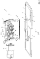
- the member 6 extends along an axis 7 and comprises two portions 8a and 8b, axially opposite each other: the portion 8a has, at one end thereof, a coupling system with a structure, shape, and size that enable the manual coupling of a portable electronic device 9 to the assembly 1, in a reference position.
- the coupling system is defined by a flange 10 that is arranged along a perimeter edge of the portion 8a, so as to define a projecting fin that lies on a plane orthogonal to the axis 7.
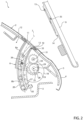
- the portion 8a In the withdrawn rest position, the portion 8a is arranged at a through opening 11 formed in the shell 4. In other words, the portion 8a engages and closes the opening 11, while the member 6 does not project into the passenger compartment, but is hidden in an inner space 12 in the dashboard 2 (except for the flange 10, which is basically flush with the surface 5). In practice, therefore, the member 6 is retractable.
- the flange 10 is arranged to rest on a seal 13 that defines the edge of the opening 11 and slides in contact with the lateral surface of the member 6, so as to seal and insulate the space 12 of the passenger compartment.
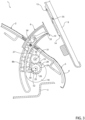
- the portion 8a projects into the passenger compartment, so that the user can easily couple and uncouple the device 9 to the member 6.
- the device 9, before being mounted on the member 6, is coupled in a fixed position to an interface element 14, which, in turn, is coupled to the portion 8a.
- the interface element 14 comprises at least one seat 15 designed to be engaged by the flange 10 so as to define a bayonet coupling (more specifically: a coupling requiring the device 9 to slide in a direction orthogonal to the axis 7, for example downwards, to engage the flange 10 in the seat 15 and, thus, bringing the device 9 into the above-mentioned reference position).
- the interface element 14 is preferably an adapter element, i.e., it is able to adapt to devices 9 with different sizes: for example, with reference to Figure 1 , the interface element 14 comprises two arms 16 that are shaped so as to engage opposite edges 17 of the device 9 and can translate, or be elastically deformed, to adapt to different widths of the device 9 (for example from 10 to 14 inches).
- the mechanism to modulate the interface element 14 could, however, be different from the configuration just described.
- the interface element 14 can be interchangeable with other interfaces that have different sizes and/or shapes, each configured to be coupled with a corresponding electronic device model.
- the portion 8a is provided with a coupling system having features that enable direct coupling with the device 9, in a releasable manner, without any interface.
- the assembly 1 comprises an electric motor 18, a transmission 19 for transmitting the movement from the motor 18 to the member 6, and a guide 20, which couples the portion 8b to the structure 3 and enables the member 6 to translate when operated by the motor 18.
- the translation trajectory defined by the guide 20 is parallel to the axis 7.
- this trajectory is an arc of a circle, with the concavity facing towards the passenger compartment and/or downwards.
- the member 6 coupling mode and the trajectory thereof are of secondary importance: for example, the guide 20 could be replaced by a hinge, lever, or articulated quadrilateral system, or it could be straight, and not curved.
- the advanced position and the withdrawn rest position of the member 6 are preferably end-of-stroke positions, defined by corresponding shoulders or stop systems: for example, the stop in the withdrawn rest position is defined by the flange 10 abutting against the seal 13.
- the corresponding stop system may be defined by the abutting of a projection 8c of the member 6, carried, for example, by the portion 8b, against an internal surface of the shell 4 and/or against the same seal 13 ( Fig. 4-6 ).
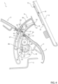
- the member 6 In the normal operating conditions, in which the user observes and uses the device 9, the member 6 is arranged in an operating position ( Figure 8 ) that does not coincide with the advanced position, in the particular example illustrated, but it is intermediate between the latter and the withdrawn rest position. However, after having coupled the device 9 to the portion 8a, the member 6 is withdrawn until it reaches this operating position, again thanks to the action of the motor 18, as will be better described below.
- the advanced position is only used to couple, and uncouple, the device 9.
- the withdrawal in the operating position is envisaged to ensure the correct opening of an airbag device, not illustrated, housed in the dashboard 2 (for example in a zone between the assembly 1 and the windscreen).
- the operating position and the advanced position may coincide (i.e., no withdrawal is envisaged after having mounted the device 9 on the portion 8a).
- the assembly 1 comprises a motor shaft 25, which is arranged in a fixed position in relation to the structure 3 (for example, it is supported by bearings that are not illustrated) and extends along a horizontal axis 26 distanced from the member 6 (and orthogonal to a longitudinal plane on which the axis lies 7).
- the shaft 25 rotates around the axis 26 when acted upon by the motor 18.
- the transmission 19 is preferably a toothed transmission comprising:
- the transmission 19 preferably further comprises at least one pair of idler gears 29 and 30: the gear 29 is carried in a fixed position by the shaft 25 and, thus, rotates together with the pinion 28, while the other gear 30 is carried in a fixed position by a transmission shaft 31 parallel to the shaft 25 and engages with the gear 29 so as to rotate the shaft 31 in the opposite direction.
- the shaft 31 is arranged in a fixed position in relation to the structure 3 (for example it is supported by bearings that are not illustrated).
- the transmission 19 comprises at least one pinion 32, which is carried in a fixed position by the shaft 31 and has a toothing that engages with the rack 27 only when the member 6 needs to shift from the advanced position to the operating one, and vice-versa, while it is disengaged from the rack 27 when the member 6 needs to shift between the two end-of-stroke positions defined by the advanced position and the withdrawn one.
- the toothings of the pinions 28 and 32 selectively engage the rack 27, i.e., the one alternates with the other, depending on the rotation angle of the motor 18 and of the shaft 25.
- the pinions 28 and 32 have the shape of a toothed wheel without a toothing for a pre-defined angle, established for each project.
- the pinions 28 and 32 could be defined by corresponding toothed segments.
- the rack 27 is preferably disengaged from both the pinions 28 and 32.
- the member 6 is arranged in the advanced position ( Figures 4 to 7 ) and is preferably held in this position, for example by the above-mentioned stop system not illustrated.
- the assembly 1 further comprises a retention member 33 that is carried by the member 6 and, when the latter is in the advanced position, it is moved to block the device 9 and/or the interface element 14 in the reference position, in order to avoid these components from being accidentally disengaged during use.
- the member 33 can be moved in relation to the other member 6 between an engaged position and a disengaged position: in the engaged position ( Fig. 5 ), the member 33 projects from the portion 8a to be coupled with a corresponding shoulder 35 of the device 9 and/or of the interface element 14, and, therefore, to avoid these components from being disengaged; in the disengaged position ( Fig. 4 ), the device 9 and the interface element 14 (if included) can be freely mounted and disassembled.
- the member 33 comprises at least one tooth or bolt 34 that can slide along the axis 7 to engage/disengage a corresponding seat formed in the interface element 14 and defining the shoulder 35 (in this way, the flange 10 is blocked from sliding in the seat 15).
- the member 33 comprises a slide 37 that carries the tooth 34 to one end thereof and is coupled to the member 6 via a guide 38.
- the trajectory defined by the guide 38 is curved (in the example illustrated, it is parallel to the axis 7). More preferably, the guide 38 is arranged at the portion 8b, and an end part of the slide 37 slides inside the portion 8a and, as mentioned above, supports the tooth 34.
- the assembly 1 also comprises an attachment and positioning device 39 that exerts a holding force that keeps the member 33 in the engaged and disengaged positions in relation to the member 6. To be able to shift the member 33, a threshold value of this force must be exceeded.
- the device 39 for example, comprises two retention seats 42 selectively engaged by a retention element 43 (for example with a spherical end), in turn pushed by a spring 44 (with a pretensioning that defines the above-mentioned threshold value).
- the retention element 43 and the spring 44 are carried by the retention member 33, in particular by an intermediate portion of the slide 37, while the seats 42 are formed in a wall of the member 6 (but, alternatively, an inverse configuration could be adopted).
- the device 39 could be of a different type, for example, it could use friction holding, instead of using the pretensioning of the spring 44 to hold the member 33.
- the member 33 is also driven by the shaft 25 via a transmission 49.
- the assembly 1 has a single motor 18 and a single shaft 25 to shift both the members 6 and 33.
- alternative solutions which have a first motor shaft dedicated to driving the member 6 and a second motor shaft dedicated to driving the other member 33, are not excluded.
- the motor 18 is preferably permanently coupled to both the transmissions 19 and 49 without using additional clutches or selectors that need to direct the motion to one or the other of these transmissions.
- the transmission 49 acts in order to translate the member 33 in relation to the other member 6 when the latter is disengaged from the pinions 28 and 32 of the transmission 19, as shown in Fig. 5 .
- the transmission 49 is a rack and pinion drive and comprises a rack 50, which is fixed in relation to the member 33 and is basically parallel to the trajectory defined by the guide 38.
- the transmission 49 further comprises a pinion 52 carried in a fixed position by the shaft 25, to drive the rack 50.
- the pinion 52 is defined by a toothed segment, but, alternatively, it could have the same configuration of the pinions 28 and 32 (toothed wheels without, for a certain angle, toothings).
- the pinion 52 meshes with the rack 50 when the member 6 is arranged
- the motor 18 stops, and the user can use the device 9 as normal. Obviously, to disassemble the device 9, these steps are performed in reverse in relation to how they are listed.
- stopping in the above-mentioned operating position preferably corresponds to the abutting of a rear projection 14a of the interface element 14 against the surface 5 of the shell 4. This abutment contributes to limiting the vibrations of the device 9 during use.
- the retention member 33 is an element driven by an actuator mounted inside the member 6.
- This actuator therefore, is carried, moving, by the member 6 when acted on by the rack 27.
- this actuator is a linear actuator, and the retention member 33 directly defined by the stem of this linear actuator, without intermediate transmissions.
- the transmission 49 i.e., the rack 50 and pinion 52
- the guide 38 and the slide 37 are absent, while the shifting of the retention member 33 and the shifting of the member 6 are driven by two actuators or motors that are distinct from each other.
- An automatic activation system is preferably provided to make the motor 18 go again, and to retract the member 6 in the operating position, after the above-mentioned actuator has driven the retention member 33 and has, therefore, locked the device 9: in other words, a sensor or a switch, e.g. defined by an electrical contact that closes a circuit, provides a consent signal when the retention member 33 reaches a predefined locking position in the corresponding seat of the interface element 14, and this signal drives the motor 18 again.
- a similar automatic system preferably causes the activation of the above-mentioned actuator to lock the device 9 when the interface element 14 is mounted on the member 6 in the predefined reference position. Therefore, this type of solution also makes it possible to recognise the correct engagement of the device 9 and to simplify the movement commands, and, potentially, to also manage an anti-pinching function.
- the pinion 32 and the idler gears 29, 20 become superfluous and may be eliminated if the rotation direction of the motor 18 can be inverted; in fact, in this case, the pinion 28 may always be meshing with the rack 27 and cause the withdrawal of the member 6 from the advanced position towards the operating position (by inverting the rotation direction of the motor 18 in relation to what is set to shift the member 6 towards the advanced position).
- toothings of gears that have an angular dimension of less than 360° enables the motor to be continuously rotated (clockwise, for example) and makes it possible to phase or adjust the timing when the pinions start to engage and disengage in relation to the racks, as a function of the rotation angle of the shaft 25.
- the parts of the toothings that are needed to achieve the required movement are selectively activated.
- the embodiment described above is particularly compact.
- the retention member 33 is driven by an actuator mounted in the member 6 and is distinct from the motor 18: in this embodiment, as explained above, the transmission 49 is absent and the transmission 19 can be simplified.
- the member 6 and/or the member 33 could have different shapes and sizes, and/or could be coupled to the device 9 and/or to the interface element 14 in different ways, compared to what is illustrated, by way of example, in the attached figures.
Landscapes
- Engineering & Computer Science (AREA)
- Mechanical Engineering (AREA)
- Lock And Its Accessories (AREA)
Abstract
Description
- This invention relates to a support and holding assembly for arranging a portable electronic device in a fixed reference position, in particular in a passenger compartment of a vehicle, to which the following discussion will make explicit reference without losing any generality thereby.
- In this regard, it is known that portable electronic devices, such as, for example, cellular phones, satellite navigators, tablets, etc., are extremely widespread and are also used in vehicles. In general, the portable electronic device is coupled so that it can be coupled in a releasable manner to a support provided in the passenger compartment. In some solutions, this support is defined by a structure carried by the dashboard of the vehicle. It projects from this dashboard upwards and, in general, has a seat or a jaw where the portable electronic device can be inserted/clamped. In other solutions, the support is defined by a structure that is attached to the windscreen of the vehicle via a suction cup.
- The first type of solutions, i.e. the one involving a support that is firmly coupled to the dashboard, is the preferred solution, since it is the safest, both as far as regarding its ensuring against undesired disengagements, and for the fact that it blocks external visibility through the windscreen less.
- There is, however, the need to improve this type of solution, in particular to be able to hide or remove the support when the portable electronic device is not coupled to this support, and to facilitate the engagement and disengagement of the portable electronic device, while continuing to ensure a high degree of safety in its positioning and holding.
- The purpose of this invention is to make a support and holding assembly for a portable electronic device, which makes it possible to fulfil, in a simple and economical manner, the requirements described above.
- According to this invention, a support and holding assembly for a portable electronic device, as defined in the attached claims from 1 to 15, and a dashboard for a vehicle as defined in
claim 16, are provided. - This invention will now be described with reference to the attached drawings that illustrate a non-limiting embodiment thereof, in which:
-
Figure 1 illustrates, in perspective from below and with parts removed for clarity, a preferred embodiment of the support and holding assembly for a portable electronic device, according to the precepts of this invention; -
Figure 2 is a cross section, according to a plane section defined by the line II-II inFigure 1 ; -
Figures 3 to 6 are similar toFigure 2 and show an action that, at first, carries the assembly from a withdrawn rest position to an advanced position and, then, locks the portable electronic device in a reference position; -
Figure 7 is a cross section, according to a plane section defined by the line VII-VII inFigure 1 , and corresponds to the operating condition shown inFigure 6 ; and -
Figure 8 is similar toFigure 7 and shows an action that withdraws the support and holding assembly from the advanced position to an operating position. - In
Figure 1 , thereference number 1 denotes, as a whole, a support and holding assembly (partially illustrated), defining a component that, in the specific described example, is part of a dashboard 2 (partially illustrated inFigures 2 to 8 ) arranged in a passenger compartment of a vehicle. - With reference to
Figure 2 , thedashboard 2 comprises asupport structure 3 and a shell 4 made of plastic, having anouter surface 5 that defines a front area of the passenger compartment. In particular, at least a part of thesurface 5 is facing upwards and, therefore, faces a windscreen (not illustrated) of the vehicle. Theassembly 1 is fixed to thestructure 3 in a manner not described in detail, and comprises asupport member 6, which can be moved in relation to thestructure 3 between a withdrawn rest position (Fig. 2 ) and an advanced position (Fig. 4-7 ). - The
member 6 extends along an axis 7 and comprises twoportions portion 8a has, at one end thereof, a coupling system with a structure, shape, and size that enable the manual coupling of a portableelectronic device 9 to theassembly 1, in a reference position. In the particular example illustrated, the coupling system is defined by aflange 10 that is arranged along a perimeter edge of theportion 8a, so as to define a projecting fin that lies on a plane orthogonal to the axis 7. - In the withdrawn rest position, the
portion 8a is arranged at a through opening 11 formed in the shell 4. In other words, theportion 8a engages and closes theopening 11, while themember 6 does not project into the passenger compartment, but is hidden in aninner space 12 in the dashboard 2 (except for theflange 10, which is basically flush with the surface 5). In practice, therefore, themember 6 is retractable. In detail, theflange 10 is arranged to rest on aseal 13 that defines the edge of theopening 11 and slides in contact with the lateral surface of themember 6, so as to seal and insulate thespace 12 of the passenger compartment. - With reference to
Figure 4 , in the advanced position, theportion 8a projects into the passenger compartment, so that the user can easily couple and uncouple thedevice 9 to themember 6. In the particular example illustrated, thedevice 9, before being mounted on themember 6, is coupled in a fixed position to aninterface element 14, which, in turn, is coupled to theportion 8a. In the particular illustrated example, theinterface element 14 comprises at least oneseat 15 designed to be engaged by theflange 10 so as to define a bayonet coupling (more specifically: a coupling requiring thedevice 9 to slide in a direction orthogonal to the axis 7, for example downwards, to engage theflange 10 in theseat 15 and, thus, bringing thedevice 9 into the above-mentioned reference position). - The
interface element 14 is preferably an adapter element, i.e., it is able to adapt todevices 9 with different sizes: for example, with reference toFigure 1 , theinterface element 14 comprises twoarms 16 that are shaped so as to engageopposite edges 17 of thedevice 9 and can translate, or be elastically deformed, to adapt to different widths of the device 9 (for example from 10 to 14 inches). The mechanism to modulate theinterface element 14 could, however, be different from the configuration just described. - Alternatively, the
interface element 14 can be interchangeable with other interfaces that have different sizes and/or shapes, each configured to be coupled with a corresponding electronic device model. - According to not illustrated variants (that could, however, be less desirable in terms of aesthetics), the
portion 8a is provided with a coupling system having features that enable direct coupling with thedevice 9, in a releasable manner, without any interface. - In order to shift between the advanced and withdrawn positions, the
assembly 1 comprises anelectric motor 18, atransmission 19 for transmitting the movement from themotor 18 to themember 6, and aguide 20, which couples theportion 8b to thestructure 3 and enables themember 6 to translate when operated by themotor 18. - In the specific illustrated example, the translation trajectory defined by the
guide 20 is parallel to the axis 7. In particular, this trajectory is an arc of a circle, with the concavity facing towards the passenger compartment and/or downwards. - In general, the
member 6 coupling mode and the trajectory thereof are of secondary importance: for example, theguide 20 could be replaced by a hinge, lever, or articulated quadrilateral system, or it could be straight, and not curved. - The advanced position and the withdrawn rest position of the
member 6 are preferably end-of-stroke positions, defined by corresponding shoulders or stop systems: for example, the stop in the withdrawn rest position is defined by theflange 10 abutting against theseal 13. For the stop in the advanced position, the corresponding stop system may be defined by the abutting of aprojection 8c of themember 6, carried, for example, by theportion 8b, against an internal surface of the shell 4 and/or against the same seal 13 (Fig. 4-6 ). - In the normal operating conditions, in which the user observes and uses the
device 9, themember 6 is arranged in an operating position (Figure 8 ) that does not coincide with the advanced position, in the particular example illustrated, but it is intermediate between the latter and the withdrawn rest position. However, after having coupled thedevice 9 to theportion 8a, themember 6 is withdrawn until it reaches this operating position, again thanks to the action of themotor 18, as will be better described below. The advanced position, however, is only used to couple, and uncouple, thedevice 9. The withdrawal in the operating position is envisaged to ensure the correct opening of an airbag device, not illustrated, housed in the dashboard 2 (for example in a zone between theassembly 1 and the windscreen). In any case, according to variants not illustrated, the operating position and the advanced position may coincide (i.e., no withdrawal is envisaged after having mounted thedevice 9 on theportion 8a). - Again, with reference to
Figure 1 , theassembly 1 comprises amotor shaft 25, which is arranged in a fixed position in relation to the structure 3 (for example, it is supported by bearings that are not illustrated) and extends along ahorizontal axis 26 distanced from the member 6 (and orthogonal to a longitudinal plane on which the axis lies 7). Theshaft 25 rotates around theaxis 26 when acted upon by themotor 18. - With reference to
Figures 1 and2 , thetransmission 19 is preferably a toothed transmission comprising: - at least one
rack 27, which is fixed in relation to themember 6 and is parallel to the trajectory defined by theguide 20; and - at least one
pinion 28, which is carried in a fixed position by theshaft 25 and has a toothing that meshes with therack 27 only when themember 6 needs to shift from the advanced position to the withdrawn one, and vice versa, while it is disengaged from therack 27 when themember 6 needs to shift from the advanced position to the operating one, and vice-versa. - The
transmission 19 preferably further comprises at least one pair ofidler gears 29 and 30: thegear 29 is carried in a fixed position by theshaft 25 and, thus, rotates together with thepinion 28, while theother gear 30 is carried in a fixed position by atransmission shaft 31 parallel to theshaft 25 and engages with thegear 29 so as to rotate theshaft 31 in the opposite direction. At the same time, theshaft 31 is arranged in a fixed position in relation to the structure 3 (for example it is supported by bearings that are not illustrated). - With reference to
Figures 1 and8 , then, thetransmission 19 comprises at least onepinion 32, which is carried in a fixed position by theshaft 31 and has a toothing that engages with therack 27 only when themember 6 needs to shift from the advanced position to the operating one, and vice-versa, while it is disengaged from therack 27 when themember 6 needs to shift between the two end-of-stroke positions defined by the advanced position and the withdrawn one. - Therefore, the toothings of the
pinions rack 27, i.e., the one alternates with the other, depending on the rotation angle of themotor 18 and of theshaft 25. In particular, thepinions pinions - For a certain rotation angle interval of the
shaft 25, therack 27 is preferably disengaged from both thepinions member 6 is arranged in the advanced position (Figures 4 to 7 ) and is preferably held in this position, for example by the above-mentioned stop system not illustrated. - With reference to
Figures 4 and5 , theassembly 1 further comprises aretention member 33 that is carried by themember 6 and, when the latter is in the advanced position, it is moved to block thedevice 9 and/or theinterface element 14 in the reference position, in order to avoid these components from being accidentally disengaged during use. - The
member 33 can be moved in relation to theother member 6 between an engaged position and a disengaged position: in the engaged position (Fig. 5 ), themember 33 projects from theportion 8a to be coupled with acorresponding shoulder 35 of thedevice 9 and/or of theinterface element 14, and, therefore, to avoid these components from being disengaged; in the disengaged position (Fig. 4 ), thedevice 9 and the interface element 14 (if included) can be freely mounted and disassembled. For example, themember 33 comprises at least one tooth orbolt 34 that can slide along the axis 7 to engage/disengage a corresponding seat formed in theinterface element 14 and defining the shoulder 35 (in this way, theflange 10 is blocked from sliding in the seat 15). - In particular, the
member 33 comprises aslide 37 that carries thetooth 34 to one end thereof and is coupled to themember 6 via aguide 38. In particular, the trajectory defined by theguide 38 is curved (in the example illustrated, it is parallel to the axis 7). More preferably, theguide 38 is arranged at theportion 8b, and an end part of theslide 37 slides inside theportion 8a and, as mentioned above, supports thetooth 34. - The
assembly 1 also comprises an attachment andpositioning device 39 that exerts a holding force that keeps themember 33 in the engaged and disengaged positions in relation to themember 6. To be able to shift themember 33, a threshold value of this force must be exceeded. Thedevice 39, for example, comprises tworetention seats 42 selectively engaged by a retention element 43 (for example with a spherical end), in turn pushed by a spring 44 (with a pretensioning that defines the above-mentioned threshold value). In detail, theretention element 43 and thespring 44 are carried by theretention member 33, in particular by an intermediate portion of theslide 37, while theseats 42 are formed in a wall of the member 6 (but, alternatively, an inverse configuration could be adopted). In each case, thedevice 39 could be of a different type, for example, it could use friction holding, instead of using the pretensioning of thespring 44 to hold themember 33. - According to one preferred aspect of this invention, the
member 33 is also driven by theshaft 25 via atransmission 49. In other words, theassembly 1 has asingle motor 18 and asingle shaft 25 to shift both themembers member 6 and a second motor shaft dedicated to driving theother member 33, are not excluded. - The
motor 18 is preferably permanently coupled to both thetransmissions transmission 49 acts in order to translate themember 33 in relation to theother member 6 when the latter is disengaged from thepinions transmission 19, as shown inFig. 5 . - The
transmission 49 is a rack and pinion drive and comprises arack 50, which is fixed in relation to themember 33 and is basically parallel to the trajectory defined by theguide 38. Thetransmission 49 further comprises apinion 52 carried in a fixed position by theshaft 25, to drive therack 50. Thepinion 52 is defined by a toothed segment, but, alternatively, it could have the same configuration of thepinions 28 and 32 (toothed wheels without, for a certain angle, toothings). Thepinion 52 meshes with therack 50 when themember 6 is arranged - in the advanced position (
Figures 4 and5 ) and - along a final part of the progress between the two end-of-stroke positions, near the advanced position (i.e., the part of the stroke between
Fig. 3 and4 ) . - The toothing of the
pinion 52 is disengaged from the rack 50: - in the remaining part of the stroke between the two end-of-stroke positions (i.e., the part of the stroke between
Fig. 2 and3 ) and - when the
member 6 shifts from the advanced position to the operating one, and vice versa (i.e., the stroke envisaged betweenFig. 7 and8 ). - In other words, when the
motor 18 is controlled to drive thetransmissions Fig. 2 : - 1. in the withdrawn position (
Fig. 2 ), the toothing of thepinion 28 meshes with therack 27; themember 33 is in the release position; thepinions racks - 2. by starting the
motor 18, theshaft 25 begins to rotate and, thus, thepinion 28 causes the translation of therack 27; thecomponents device 39; themember 33 remains, therefore, in the release position, while thepinions racks - 3. while the
shaft 25 continues to rotate, at the advanced position (Fig. 3 ), the toothing of thepinion 52 begins to engage therack 50; themembers pinion 32 continues to idle; - 4. when the
member 6 reaches the advanced position (Fig. 4 ), themotor 18 stops; the toothing of thepinion 28 has finished its task and is just disengaged from therack 27, while the toothing of thepinion 52 continues to engage therack 50; - 5. after having mounted the
device 9 on the assembly 1 (Fig. 5 ), themotor 18 is restarted (via a manual command by the user, or via a signal from a sensor or a switch, e.g. defined by an electrical contact that automatically closes a circuit, when theinterface element 14 is mounted on themember 6 and the latter reaches its predefined reference position in theseat 15 of the interface element 14), so that the toothing of thepinion 52, by rotating, acts on therack 50, overtakes the retention action of thedevice 39, and causes themember 33 to shift into the engaged position; at the same time, thepinions rack 27 is free), while themember 6 remains in the advanced position (e.g. held by the friction of theseal 13 against theportion 8a, and/or by a stop system, not illustrated and possibly similar to the device 39); - 6. continuing to rotate the
shaft 25, and thus thepinion 52, the latter is disengaged from the rack 50 (seeFig. 6 , where this step is illustrated in an approximate way), while themember 33 remains in the engaged position, and thepinion 28 continues to idle; - 7. at the same time, the toothing of the
pinion 32 starts to engage the rack 27 (Fig. 7 ); at this point, with thepinions racks 27 and, respectively, 50, themember 6 starts to withdraw due to the action of thepinion 32 to be brought from the advanced position into the operating position (Fig. 8 ), while themember 33 remains in the engaged position. - Once the operating position is reached, the
motor 18 stops, and the user can use thedevice 9 as normal. Obviously, to disassemble thedevice 9, these steps are performed in reverse in relation to how they are listed. - As can be seen in
Figure 8 , stopping in the above-mentioned operating position preferably corresponds to the abutting of arear projection 14a of theinterface element 14 against thesurface 5 of the shell 4. This abutment contributes to limiting the vibrations of thedevice 9 during use. - The steps listed under
reference numbers 6 and 7 could be left out if the advanced and operating positions are the same (in this variant, not illustrated, theassembly 1 would not have any idler gears 29 and 30, theshaft 31, and the pinion 32). - According to an embodiment which is not illustrated, the
retention member 33 is an element driven by an actuator mounted inside themember 6. This actuator, therefore, is carried, moving, by themember 6 when acted on by therack 27. In particular, this actuator is a linear actuator, and theretention member 33 directly defined by the stem of this linear actuator, without intermediate transmissions. In this embodiment, therefore, the transmission 49 (i.e., therack 50 and pinion 52), and preferably also theguide 38 and theslide 37, are absent, while the shifting of theretention member 33 and the shifting of themember 6 are driven by two actuators or motors that are distinct from each other. - An automatic activation system is preferably provided to make the
motor 18 go again, and to retract themember 6 in the operating position, after the above-mentioned actuator has driven theretention member 33 and has, therefore, locked the device 9: in other words, a sensor or a switch, e.g. defined by an electrical contact that closes a circuit, provides a consent signal when theretention member 33 reaches a predefined locking position in the corresponding seat of theinterface element 14, and this signal drives themotor 18 again. A similar automatic system preferably causes the activation of the above-mentioned actuator to lock thedevice 9 when theinterface element 14 is mounted on themember 6 in the predefined reference position. Therefore, this type of solution also makes it possible to recognise the correct engagement of thedevice 9 and to simplify the movement commands, and, potentially, to also manage an anti-pinching function. - In addition, with this embodiment, the
pinion 32 and the idler gears 29, 20 become superfluous and may be eliminated if the rotation direction of themotor 18 can be inverted; in fact, in this case, thepinion 28 may always be meshing with therack 27 and cause the withdrawal of themember 6 from the advanced position towards the operating position (by inverting the rotation direction of themotor 18 in relation to what is set to shift themember 6 towards the advanced position). - From the above, it is clear how the
assembly 1 is retractable, inside thedashboard 2, and makes it possible to lock thedevice 9 simply and securely thanks to the action of themember 33. In particular, it should be clear how the operations for coupling and uncoupling thedevice 9 are extremely simple since the user does not manually intervene to directly operate themember 33, since this action is motorised. - Furthermore, considering the preferred illustrated embodiment, the fact of using just one
motor 18 to drive both themembers - The use of toothings of gears that have an angular dimension of less than 360° enables the motor to be continuously rotated (clockwise, for example) and makes it possible to phase or adjust the timing when the pinions start to engage and disengage in relation to the racks, as a function of the rotation angle of the
shaft 25. In other words, by continuously rotating the motor in a single rotation direction, the parts of the toothings that are needed to achieve the required movement are selectively activated. - In addition, as mentioned above, in order to alternately activate the transmissions clutches or selectors are preferably not used, and the
motor 18 is always coupled to these transmissions so that the obtained solution is compact and has a relatively small number of components. - In addition, the embodiment described above is particularly compact. In this embodiment, the
retention member 33 is driven by an actuator mounted in themember 6 and is distinct from the motor 18: in this embodiment, as explained above, thetransmission 49 is absent and thetransmission 19 can be simplified. - From the above, it is clear, finally, how the
assembly 1 described can be modified, or variants thereof produced, which do not go beyond the scope of protection of the present invention. - In particular, the
member 6 and/or themember 33 could have different shapes and sizes, and/or could be coupled to thedevice 9 and/or to theinterface element 14 in different ways, compared to what is illustrated, by way of example, in the attached figures.
Claims (15)
- A support and holding assembly (1) for a portable electronic device (9), the assembly comprising:- a support structure (3);- a support member (6) that has, at one end, a coupling portion (10), to which said portable electronic device can be coupled, in use, in order to be arranged in a reference position; the support member (6) being movable between a withdrawn rest position and an advanced position in relation to said support structure (3);- a retention member (33), that is carried by said support member (6) and can be moved in relation to said support member (6) betweena) an engaged position, in which the retention member (33) holds, in use, the portable electronic device in the reference position in relation to said support component, andb) a disengaged position, in which the portable electronic device is free to be coupled to, and uncoupled from, said coupling portion (10);- at least one motor or actuator (18);- a first transmission (19) driven by said motor or actuator (18) in order to shift said support member (6) between the withdrawn rest position and the advanced position.
- The assembly according to claim 1, further comprising a second transmission (49) to shift said retention member (33) between the engaged position and the disengaged position.
- The assembly according to claim 2, wherein said second transmission (49) is also driven by said motor or actuator (18).
- The assembly according to claim 2 or 3, wherein at least one of said first and second transmission (19, 49) comprises a rack and pinion drive.
- The assembly according to claim 4, wherein said first and second transmissions (19, 49) comprise respective rack and pinion drives.
- The assembly according to any of the previous claims from 2 to 5, further comprising a transmission shaft (25) permanently coupled to said first and second transmission (19, 49).
- The assembly according to claim 6, wherein said first and second transmission (49) are configured so as to shift said retention member (33) between the engaged position and the disengaged position only when said support member (6) is arranged in the advanced position.
- The assembly according to claim 6 or 7, wherein:- said first transmission comprises a first pinion and a first toothing carried by said support member (6);- said second transmission comprises a second pinion and a second toothing (50) carried by said retention member (33) ;- the first and second pinions comprise corresponding toothed segments arranged in angular positions so that, when said first pinion is disengaged from said first toothing (27), said second pinion meshes with said second toothing (50) so as to cause, by rotation, the movement of said retention member (33).
- The assembly according to claim 8, wherein said first and second pinions are carried in fixed and coaxial positions on said transmission shaft (25).
- The assembly according to claim 8 or 9, wherein at least one of said first and second toothings (27, 50) is defined by a rack.
- The assembly according to claim 10, characterised in that said rack extends along a curved trajectory.
- The assembly according to claims 8 to 11, wherein said first transmission (19) comprises:- an additional pinion, and- a pair of idler gears, which transmit and invert a rotary motion between said first pinion and said additional pinion.
- The assembly according to claim 12, wherein said additional pinion has a toothed segment that engages with said first toothing (27) only when said first and second pinions are disengaged respectively from said first and second toothings.
- The assembly according to claim 1 or 2, comprising an additional motor or actuator carried by said support member (6) and distinct from said at least one motor or actuator (18); said retention member (33) being driven by said additional motor or actuator.
- A vehicle dashboard, comprising a support and holding assembly (1) for a portable electronic device (9) according to any of the previous claims.
Priority Applications (2)
| Application Number | Priority Date | Filing Date | Title |
|---|---|---|---|
| EP21195334.4A EP4144589B1 (en) | 2021-09-07 | 2021-09-07 | A support and holding assembly for a portable electronic device, and a vehicle dashboard provided with this support and holding assembly |
| US17/890,353 US20230076954A1 (en) | 2021-09-07 | 2022-08-18 | A Support And Holding Assembly For A Portable Electronic Device, And A Vehicle Dashboard Provided With This Support And Holding Assembly |
Applications Claiming Priority (1)
| Application Number | Priority Date | Filing Date | Title |
|---|---|---|---|
| EP21195334.4A EP4144589B1 (en) | 2021-09-07 | 2021-09-07 | A support and holding assembly for a portable electronic device, and a vehicle dashboard provided with this support and holding assembly |
Publications (2)
| Publication Number | Publication Date |
|---|---|
| EP4144589A1 true EP4144589A1 (en) | 2023-03-08 |
| EP4144589B1 EP4144589B1 (en) | 2024-05-08 |
Family
ID=78401991
Family Applications (1)
| Application Number | Title | Priority Date | Filing Date |
|---|---|---|---|
| EP21195334.4A Active EP4144589B1 (en) | 2021-09-07 | 2021-09-07 | A support and holding assembly for a portable electronic device, and a vehicle dashboard provided with this support and holding assembly |
Country Status (2)
| Country | Link |
|---|---|
| US (1) | US20230076954A1 (en) |
| EP (1) | EP4144589B1 (en) |
Citations (4)
| Publication number | Priority date | Publication date | Assignee | Title |
|---|---|---|---|---|
| DE102009036326B3 (en) * | 2009-08-05 | 2010-07-08 | Faurecia Innenraum Systeme Gmbh | Storage compartment for use as holder of multimedia device i.e. navigation equipment, in interior of motor vehicle, has acceleration element that is released in release position of release device for moving cover to closed position |
| DE202011106185U1 (en) * | 2010-09-30 | 2011-12-22 | Faurecia Interieur Industrie | Mounting bracket for a portable electronic device, as well as corresponding dashboard and motor vehicle |
| EP2546105A1 (en) * | 2011-07-14 | 2013-01-16 | LG Electronics Inc. | Holding apparatus for portable electronic device |
| US20140203585A1 (en) * | 2013-01-23 | 2014-07-24 | Ford Global Technologies, Llc | Vehicle portable device holding system |
Family Cites Families (5)
| Publication number | Priority date | Publication date | Assignee | Title |
|---|---|---|---|---|
| KR0180896B1 (en) * | 1996-07-19 | 1999-05-15 | 정인현 | Stored apparatus for a portable personal communication terminal |
| US20040179678A1 (en) * | 2003-03-14 | 2004-09-16 | Hsiu-Chu Hsu Li | Cradle for supporting various portable phones |
| KR101276244B1 (en) * | 2011-07-26 | 2013-06-20 | 현대모비스 주식회사 | Pop-Up Monitor with obstacle sensing function |
| FR2999996B1 (en) * | 2012-12-21 | 2015-02-27 | Renault Sa | MULTIMEDIA SCREEN SUPPORT IN PARTICULAR FOR A DASHBOARD OF A MOTOR VEHICLE |
| FR3005617B1 (en) * | 2013-05-17 | 2016-09-02 | Faurecia Interieur Ind | DEVICE FOR SUPPORTING A PORTABLE ELECTRONIC APPARATUS, DASHBOARD EQUIPPED WITH SUCH A DEVICE |
-
2021
- 2021-09-07 EP EP21195334.4A patent/EP4144589B1/en active Active
-
2022
- 2022-08-18 US US17/890,353 patent/US20230076954A1/en not_active Abandoned
Patent Citations (4)
| Publication number | Priority date | Publication date | Assignee | Title |
|---|---|---|---|---|
| DE102009036326B3 (en) * | 2009-08-05 | 2010-07-08 | Faurecia Innenraum Systeme Gmbh | Storage compartment for use as holder of multimedia device i.e. navigation equipment, in interior of motor vehicle, has acceleration element that is released in release position of release device for moving cover to closed position |
| DE202011106185U1 (en) * | 2010-09-30 | 2011-12-22 | Faurecia Interieur Industrie | Mounting bracket for a portable electronic device, as well as corresponding dashboard and motor vehicle |
| EP2546105A1 (en) * | 2011-07-14 | 2013-01-16 | LG Electronics Inc. | Holding apparatus for portable electronic device |
| US20140203585A1 (en) * | 2013-01-23 | 2014-07-24 | Ford Global Technologies, Llc | Vehicle portable device holding system |
Also Published As
| Publication number | Publication date |
|---|---|
| US20230076954A1 (en) | 2023-03-09 |
| EP4144589B1 (en) | 2024-05-08 |
Similar Documents
| Publication | Publication Date | Title |
|---|---|---|
| CN106895139B (en) | Gear shift device | |
| EP3021009A1 (en) | Shift device | |
| EP3181957B1 (en) | Shift by wire transmission shift control system with park release | |
| JP6371382B2 (en) | Device for displacing an operating element of an automatic transmission of a vehicle to a parking position, a method for operating such a device and a shift device for shifting an automatic transmission of a vehicle | |
| EP3508671B1 (en) | Electric door lock mechanism and method to override | |
| CN102700440B (en) | Articulation system and vehicle seat comprising such an articulation system | |
| US8985295B2 (en) | Parking interlock arrangement for an automatic transmission | |
| EP2650561B1 (en) | Output member and multi-shaft drive device | |
| JP2011098677A (en) | Parking locking device | |
| EP4534385A1 (en) | Steering wheel and vehicle | |
| EP4144589B1 (en) | A support and holding assembly for a portable electronic device, and a vehicle dashboard provided with this support and holding assembly | |
| CN212106898U (en) | Parking device and vehicle | |
| EP2725569B1 (en) | Display holding mechanism and openable display apparatus | |
| EP3412509B1 (en) | Actuator mechanism for a fold rear-view mirror assembly | |
| EP3246600A1 (en) | Transmission shifter with multi-position lockout | |
| CN112696493A (en) | Electromechanical parking lock actuator | |
| EP2515003B1 (en) | Shifting device | |
| CN112360975A (en) | Parking mechanism of automobile transmission | |
| KR101374524B1 (en) | Manual Lumber Support Device of Seat | |
| EP3091256B1 (en) | Shift by wire shifting device | |
| EP3275740B1 (en) | Clutch for a seat belt tensioner and method for transferring a clutch from an engaged position into a decoupled position | |
| KR100661726B1 (en) | Cars for automatic transmission | |
| CN211259610U (en) | parking lock | |
| KR20150002057A (en) | Driving Apparatus for Seat Belt | |
| JP2014083909A (en) | Steering lock device |
Legal Events
| Date | Code | Title | Description |
|---|---|---|---|
| PUAI | Public reference made under article 153(3) epc to a published international application that has entered the european phase |
Free format text: ORIGINAL CODE: 0009012 |
|
| STAA | Information on the status of an ep patent application or granted ep patent |
Free format text: STATUS: THE APPLICATION HAS BEEN PUBLISHED |
|
| AK | Designated contracting states |
Kind code of ref document: A1 Designated state(s): AL AT BE BG CH CY CZ DE DK EE ES FI FR GB GR HR HU IE IS IT LI LT LU LV MC MK MT NL NO PL PT RO RS SE SI SK SM TR |
|
| STAA | Information on the status of an ep patent application or granted ep patent |
Free format text: STATUS: REQUEST FOR EXAMINATION WAS MADE |
|
| 17P | Request for examination filed |
Effective date: 20230904 |
|
| RBV | Designated contracting states (corrected) |
Designated state(s): AL AT BE BG CH CY CZ DE DK EE ES FI FR GB GR HR HU IE IS IT LI LT LU LV MC MK MT NL NO PL PT RO RS SE SI SK SM TR |
|
| RAP3 | Party data changed (applicant data changed or rights of an application transferred) |
Owner name: STELLANTIS EUROPE S.P.A. |
|
| GRAP | Despatch of communication of intention to grant a patent |
Free format text: ORIGINAL CODE: EPIDOSNIGR1 |
|
| STAA | Information on the status of an ep patent application or granted ep patent |
Free format text: STATUS: GRANT OF PATENT IS INTENDED |
|
| INTG | Intention to grant announced |
Effective date: 20231208 |
|
| GRAS | Grant fee paid |
Free format text: ORIGINAL CODE: EPIDOSNIGR3 |
|
| GRAA | (expected) grant |
Free format text: ORIGINAL CODE: 0009210 |
|
| STAA | Information on the status of an ep patent application or granted ep patent |
Free format text: STATUS: THE PATENT HAS BEEN GRANTED |
|
| AK | Designated contracting states |
Kind code of ref document: B1 Designated state(s): AL AT BE BG CH CY CZ DE DK EE ES FI FR GB GR HR HU IE IS IT LI LT LU LV MC MK MT NL NO PL PT RO RS SE SI SK SM TR |
|
| REG | Reference to a national code |
Ref country code: GB Ref legal event code: FG4D |
|
| REG | Reference to a national code |
Ref country code: CH Ref legal event code: EP |
|
| REG | Reference to a national code |
Ref country code: DE Ref legal event code: R096 Ref document number: 602021012985 Country of ref document: DE |
|
| REG | Reference to a national code |
Ref country code: IE Ref legal event code: FG4D |
|
| REG | Reference to a national code |
Ref country code: LT Ref legal event code: MG9D |
|
| REG | Reference to a national code |
Ref country code: NL Ref legal event code: MP Effective date: 20240508 |
|
| PG25 | Lapsed in a contracting state [announced via postgrant information from national office to epo] |
Ref country code: IS Free format text: LAPSE BECAUSE OF FAILURE TO SUBMIT A TRANSLATION OF THE DESCRIPTION OR TO PAY THE FEE WITHIN THE PRESCRIBED TIME-LIMIT Effective date: 20240908 |
|
| PG25 | Lapsed in a contracting state [announced via postgrant information from national office to epo] |
Ref country code: BG Free format text: LAPSE BECAUSE OF FAILURE TO SUBMIT A TRANSLATION OF THE DESCRIPTION OR TO PAY THE FEE WITHIN THE PRESCRIBED TIME-LIMIT Effective date: 20240508 |
|
| PG25 | Lapsed in a contracting state [announced via postgrant information from national office to epo] |
Ref country code: FI Free format text: LAPSE BECAUSE OF FAILURE TO SUBMIT A TRANSLATION OF THE DESCRIPTION OR TO PAY THE FEE WITHIN THE PRESCRIBED TIME-LIMIT Effective date: 20240508 Ref country code: HR Free format text: LAPSE BECAUSE OF FAILURE TO SUBMIT A TRANSLATION OF THE DESCRIPTION OR TO PAY THE FEE WITHIN THE PRESCRIBED TIME-LIMIT Effective date: 20240508 |
|
| PG25 | Lapsed in a contracting state [announced via postgrant information from national office to epo] |
Ref country code: GR Free format text: LAPSE BECAUSE OF FAILURE TO SUBMIT A TRANSLATION OF THE DESCRIPTION OR TO PAY THE FEE WITHIN THE PRESCRIBED TIME-LIMIT Effective date: 20240809 |
|
| PG25 | Lapsed in a contracting state [announced via postgrant information from national office to epo] |
Ref country code: PT Free format text: LAPSE BECAUSE OF FAILURE TO SUBMIT A TRANSLATION OF THE DESCRIPTION OR TO PAY THE FEE WITHIN THE PRESCRIBED TIME-LIMIT Effective date: 20240909 |
|
| REG | Reference to a national code |
Ref country code: AT Ref legal event code: MK05 Ref document number: 1684748 Country of ref document: AT Kind code of ref document: T Effective date: 20240508 |
|
| PG25 | Lapsed in a contracting state [announced via postgrant information from national office to epo] |
Ref country code: NL Free format text: LAPSE BECAUSE OF FAILURE TO SUBMIT A TRANSLATION OF THE DESCRIPTION OR TO PAY THE FEE WITHIN THE PRESCRIBED TIME-LIMIT Effective date: 20240508 |
|
| PG25 | Lapsed in a contracting state [announced via postgrant information from national office to epo] |
Ref country code: ES Free format text: LAPSE BECAUSE OF FAILURE TO SUBMIT A TRANSLATION OF THE DESCRIPTION OR TO PAY THE FEE WITHIN THE PRESCRIBED TIME-LIMIT Effective date: 20240508 |
|
| PG25 | Lapsed in a contracting state [announced via postgrant information from national office to epo] |
Ref country code: AT Free format text: LAPSE BECAUSE OF FAILURE TO SUBMIT A TRANSLATION OF THE DESCRIPTION OR TO PAY THE FEE WITHIN THE PRESCRIBED TIME-LIMIT Effective date: 20240508 |
|
| PG25 | Lapsed in a contracting state [announced via postgrant information from national office to epo] |
Ref country code: PL Free format text: LAPSE BECAUSE OF FAILURE TO SUBMIT A TRANSLATION OF THE DESCRIPTION OR TO PAY THE FEE WITHIN THE PRESCRIBED TIME-LIMIT Effective date: 20240508 |
|
| PG25 | Lapsed in a contracting state [announced via postgrant information from national office to epo] |
Ref country code: LV Free format text: LAPSE BECAUSE OF FAILURE TO SUBMIT A TRANSLATION OF THE DESCRIPTION OR TO PAY THE FEE WITHIN THE PRESCRIBED TIME-LIMIT Effective date: 20240508 |
|
| PG25 | Lapsed in a contracting state [announced via postgrant information from national office to epo] |
Ref country code: PT Free format text: LAPSE BECAUSE OF FAILURE TO SUBMIT A TRANSLATION OF THE DESCRIPTION OR TO PAY THE FEE WITHIN THE PRESCRIBED TIME-LIMIT Effective date: 20240909 Ref country code: PL Free format text: LAPSE BECAUSE OF FAILURE TO SUBMIT A TRANSLATION OF THE DESCRIPTION OR TO PAY THE FEE WITHIN THE PRESCRIBED TIME-LIMIT Effective date: 20240508 Ref country code: NO Free format text: LAPSE BECAUSE OF FAILURE TO SUBMIT A TRANSLATION OF THE DESCRIPTION OR TO PAY THE FEE WITHIN THE PRESCRIBED TIME-LIMIT Effective date: 20240808 Ref country code: NL Free format text: LAPSE BECAUSE OF FAILURE TO SUBMIT A TRANSLATION OF THE DESCRIPTION OR TO PAY THE FEE WITHIN THE PRESCRIBED TIME-LIMIT Effective date: 20240508 Ref country code: LV Free format text: LAPSE BECAUSE OF FAILURE TO SUBMIT A TRANSLATION OF THE DESCRIPTION OR TO PAY THE FEE WITHIN THE PRESCRIBED TIME-LIMIT Effective date: 20240508 Ref country code: IS Free format text: LAPSE BECAUSE OF FAILURE TO SUBMIT A TRANSLATION OF THE DESCRIPTION OR TO PAY THE FEE WITHIN THE PRESCRIBED TIME-LIMIT Effective date: 20240908 Ref country code: HR Free format text: LAPSE BECAUSE OF FAILURE TO SUBMIT A TRANSLATION OF THE DESCRIPTION OR TO PAY THE FEE WITHIN THE PRESCRIBED TIME-LIMIT Effective date: 20240508 Ref country code: GR Free format text: LAPSE BECAUSE OF FAILURE TO SUBMIT A TRANSLATION OF THE DESCRIPTION OR TO PAY THE FEE WITHIN THE PRESCRIBED TIME-LIMIT Effective date: 20240809 Ref country code: FI Free format text: LAPSE BECAUSE OF FAILURE TO SUBMIT A TRANSLATION OF THE DESCRIPTION OR TO PAY THE FEE WITHIN THE PRESCRIBED TIME-LIMIT Effective date: 20240508 Ref country code: ES Free format text: LAPSE BECAUSE OF FAILURE TO SUBMIT A TRANSLATION OF THE DESCRIPTION OR TO PAY THE FEE WITHIN THE PRESCRIBED TIME-LIMIT Effective date: 20240508 Ref country code: BG Free format text: LAPSE BECAUSE OF FAILURE TO SUBMIT A TRANSLATION OF THE DESCRIPTION OR TO PAY THE FEE WITHIN THE PRESCRIBED TIME-LIMIT Effective date: 20240508 Ref country code: AT Free format text: LAPSE BECAUSE OF FAILURE TO SUBMIT A TRANSLATION OF THE DESCRIPTION OR TO PAY THE FEE WITHIN THE PRESCRIBED TIME-LIMIT Effective date: 20240508 Ref country code: RS Free format text: LAPSE BECAUSE OF FAILURE TO SUBMIT A TRANSLATION OF THE DESCRIPTION OR TO PAY THE FEE WITHIN THE PRESCRIBED TIME-LIMIT Effective date: 20240808 |
|
| PG25 | Lapsed in a contracting state [announced via postgrant information from national office to epo] |
Ref country code: DK Free format text: LAPSE BECAUSE OF FAILURE TO SUBMIT A TRANSLATION OF THE DESCRIPTION OR TO PAY THE FEE WITHIN THE PRESCRIBED TIME-LIMIT Effective date: 20240508 |
|
| PG25 | Lapsed in a contracting state [announced via postgrant information from national office to epo] |
Ref country code: EE Free format text: LAPSE BECAUSE OF FAILURE TO SUBMIT A TRANSLATION OF THE DESCRIPTION OR TO PAY THE FEE WITHIN THE PRESCRIBED TIME-LIMIT Effective date: 20240508 |
|
| PG25 | Lapsed in a contracting state [announced via postgrant information from national office to epo] |
Ref country code: CZ Free format text: LAPSE BECAUSE OF FAILURE TO SUBMIT A TRANSLATION OF THE DESCRIPTION OR TO PAY THE FEE WITHIN THE PRESCRIBED TIME-LIMIT Effective date: 20240508 |
|
| PG25 | Lapsed in a contracting state [announced via postgrant information from national office to epo] |
Ref country code: RO Free format text: LAPSE BECAUSE OF FAILURE TO SUBMIT A TRANSLATION OF THE DESCRIPTION OR TO PAY THE FEE WITHIN THE PRESCRIBED TIME-LIMIT Effective date: 20240508 Ref country code: SK Free format text: LAPSE BECAUSE OF FAILURE TO SUBMIT A TRANSLATION OF THE DESCRIPTION OR TO PAY THE FEE WITHIN THE PRESCRIBED TIME-LIMIT Effective date: 20240508 |
|
| PG25 | Lapsed in a contracting state [announced via postgrant information from national office to epo] |
Ref country code: SM Free format text: LAPSE BECAUSE OF FAILURE TO SUBMIT A TRANSLATION OF THE DESCRIPTION OR TO PAY THE FEE WITHIN THE PRESCRIBED TIME-LIMIT Effective date: 20240508 |
|
| PG25 | Lapsed in a contracting state [announced via postgrant information from national office to epo] |
Ref country code: SM Free format text: LAPSE BECAUSE OF FAILURE TO SUBMIT A TRANSLATION OF THE DESCRIPTION OR TO PAY THE FEE WITHIN THE PRESCRIBED TIME-LIMIT Effective date: 20240508 Ref country code: SK Free format text: LAPSE BECAUSE OF FAILURE TO SUBMIT A TRANSLATION OF THE DESCRIPTION OR TO PAY THE FEE WITHIN THE PRESCRIBED TIME-LIMIT Effective date: 20240508 Ref country code: RO Free format text: LAPSE BECAUSE OF FAILURE TO SUBMIT A TRANSLATION OF THE DESCRIPTION OR TO PAY THE FEE WITHIN THE PRESCRIBED TIME-LIMIT Effective date: 20240508 Ref country code: EE Free format text: LAPSE BECAUSE OF FAILURE TO SUBMIT A TRANSLATION OF THE DESCRIPTION OR TO PAY THE FEE WITHIN THE PRESCRIBED TIME-LIMIT Effective date: 20240508 Ref country code: DK Free format text: LAPSE BECAUSE OF FAILURE TO SUBMIT A TRANSLATION OF THE DESCRIPTION OR TO PAY THE FEE WITHIN THE PRESCRIBED TIME-LIMIT Effective date: 20240508 Ref country code: CZ Free format text: LAPSE BECAUSE OF FAILURE TO SUBMIT A TRANSLATION OF THE DESCRIPTION OR TO PAY THE FEE WITHIN THE PRESCRIBED TIME-LIMIT Effective date: 20240508 |
|
| REG | Reference to a national code |
Ref country code: DE Ref legal event code: R097 Ref document number: 602021012985 Country of ref document: DE |
|
| PLBE | No opposition filed within time limit |
Free format text: ORIGINAL CODE: 0009261 |
|
| STAA | Information on the status of an ep patent application or granted ep patent |
Free format text: STATUS: NO OPPOSITION FILED WITHIN TIME LIMIT |
|
| 26N | No opposition filed |
Effective date: 20250211 |
|
| PG25 | Lapsed in a contracting state [announced via postgrant information from national office to epo] |
Ref country code: SI Free format text: LAPSE BECAUSE OF FAILURE TO SUBMIT A TRANSLATION OF THE DESCRIPTION OR TO PAY THE FEE WITHIN THE PRESCRIBED TIME-LIMIT Effective date: 20240508 Ref country code: MC Free format text: LAPSE BECAUSE OF FAILURE TO SUBMIT A TRANSLATION OF THE DESCRIPTION OR TO PAY THE FEE WITHIN THE PRESCRIBED TIME-LIMIT Effective date: 20240508 |
|
| REG | Reference to a national code |
Ref country code: CH Ref legal event code: PL |
|
| PG25 | Lapsed in a contracting state [announced via postgrant information from national office to epo] |
Ref country code: LU Free format text: LAPSE BECAUSE OF NON-PAYMENT OF DUE FEES Effective date: 20240907 |
|
| REG | Reference to a national code |
Ref country code: BE Ref legal event code: MM Effective date: 20240930 |
|
| PG25 | Lapsed in a contracting state [announced via postgrant information from national office to epo] |
Ref country code: BE Free format text: LAPSE BECAUSE OF NON-PAYMENT OF DUE FEES Effective date: 20240930 |
|
| PG25 | Lapsed in a contracting state [announced via postgrant information from national office to epo] |
Ref country code: CH Free format text: LAPSE BECAUSE OF NON-PAYMENT OF DUE FEES Effective date: 20240930 |
|
| PG25 | Lapsed in a contracting state [announced via postgrant information from national office to epo] |
Ref country code: IE Free format text: LAPSE BECAUSE OF NON-PAYMENT OF DUE FEES Effective date: 20240907 |
|
| PG25 | Lapsed in a contracting state [announced via postgrant information from national office to epo] |
Ref country code: SE Free format text: LAPSE BECAUSE OF FAILURE TO SUBMIT A TRANSLATION OF THE DESCRIPTION OR TO PAY THE FEE WITHIN THE PRESCRIBED TIME-LIMIT Effective date: 20240508 |
|
| PGFP | Annual fee paid to national office [announced via postgrant information from national office to epo] |
Ref country code: DE Payment date: 20250820 Year of fee payment: 5 |
|
| PGFP | Annual fee paid to national office [announced via postgrant information from national office to epo] |
Ref country code: IT Payment date: 20250820 Year of fee payment: 5 |
|
| PGFP | Annual fee paid to national office [announced via postgrant information from national office to epo] |
Ref country code: FR Payment date: 20250821 Year of fee payment: 5 |
|
| REG | Reference to a national code |
Ref country code: DE Ref legal event code: R084 Ref document number: 602021012985 Country of ref document: DE |
|
| PG25 | Lapsed in a contracting state [announced via postgrant information from national office to epo] |
Ref country code: CY Free format text: LAPSE BECAUSE OF FAILURE TO SUBMIT A TRANSLATION OF THE DESCRIPTION OR TO PAY THE FEE WITHIN THE PRESCRIBED TIME-LIMIT; INVALID AB INITIO Effective date: 20210907 |
|
| PG25 | Lapsed in a contracting state [announced via postgrant information from national office to epo] |
Ref country code: HU Free format text: LAPSE BECAUSE OF FAILURE TO SUBMIT A TRANSLATION OF THE DESCRIPTION OR TO PAY THE FEE WITHIN THE PRESCRIBED TIME-LIMIT; INVALID AB INITIO Effective date: 20210907 |