EP4144572A1 - Electrical connector for an electric vehicle having power and signal terminals - Google Patents
Electrical connector for an electric vehicle having power and signal terminals Download PDFInfo
- Publication number
- EP4144572A1 EP4144572A1 EP21212751.8A EP21212751A EP4144572A1 EP 4144572 A1 EP4144572 A1 EP 4144572A1 EP 21212751 A EP21212751 A EP 21212751A EP 4144572 A1 EP4144572 A1 EP 4144572A1
- Authority
- EP
- European Patent Office
- Prior art keywords
- power terminal
- terminal
- region
- distance
- signal terminals
- Prior art date
- Legal status (The legal status is an assumption and is not a legal conclusion. Google has not performed a legal analysis and makes no representation as to the accuracy of the status listed.)
- Pending
Links
- 238000004891 communication Methods 0.000 claims description 9
- 238000012790 confirmation Methods 0.000 claims description 9
- 238000001514 detection method Methods 0.000 claims description 7
- 238000012360 testing method Methods 0.000 claims description 3
- 230000002093 peripheral effect Effects 0.000 claims description 2
- 230000002452 interceptive effect Effects 0.000 abstract description 6
- 230000008054 signal transmission Effects 0.000 description 8
- 230000005611 electricity Effects 0.000 description 4
- 238000009413 insulation Methods 0.000 description 2
- 238000000034 method Methods 0.000 description 2
- 230000005540 biological transmission Effects 0.000 description 1
- 238000013461 design Methods 0.000 description 1
- 238000005516 engineering process Methods 0.000 description 1
- 230000007613 environmental effect Effects 0.000 description 1
- 238000012544 monitoring process Methods 0.000 description 1
- 238000012827 research and development Methods 0.000 description 1
- 239000000523 sample Substances 0.000 description 1
Images


Classifications
-
- B—PERFORMING OPERATIONS; TRANSPORTING
- B60—VEHICLES IN GENERAL
- B60L—PROPULSION OF ELECTRICALLY-PROPELLED VEHICLES; SUPPLYING ELECTRIC POWER FOR AUXILIARY EQUIPMENT OF ELECTRICALLY-PROPELLED VEHICLES; ELECTRODYNAMIC BRAKE SYSTEMS FOR VEHICLES IN GENERAL; MAGNETIC SUSPENSION OR LEVITATION FOR VEHICLES; MONITORING OPERATING VARIABLES OF ELECTRICALLY-PROPELLED VEHICLES; ELECTRIC SAFETY DEVICES FOR ELECTRICALLY-PROPELLED VEHICLES
- B60L53/00—Methods of charging batteries, specially adapted for electric vehicles; Charging stations or on-board charging equipment therefor; Exchange of energy storage elements in electric vehicles
- B60L53/10—Methods of charging batteries, specially adapted for electric vehicles; Charging stations or on-board charging equipment therefor; Exchange of energy storage elements in electric vehicles characterised by the energy transfer between the charging station and the vehicle
- B60L53/14—Conductive energy transfer
- B60L53/16—Connectors, e.g. plugs or sockets, specially adapted for charging electric vehicles
-
- B—PERFORMING OPERATIONS; TRANSPORTING
- B60—VEHICLES IN GENERAL
- B60L—PROPULSION OF ELECTRICALLY-PROPELLED VEHICLES; SUPPLYING ELECTRIC POWER FOR AUXILIARY EQUIPMENT OF ELECTRICALLY-PROPELLED VEHICLES; ELECTRODYNAMIC BRAKE SYSTEMS FOR VEHICLES IN GENERAL; MAGNETIC SUSPENSION OR LEVITATION FOR VEHICLES; MONITORING OPERATING VARIABLES OF ELECTRICALLY-PROPELLED VEHICLES; ELECTRIC SAFETY DEVICES FOR ELECTRICALLY-PROPELLED VEHICLES
- B60L53/00—Methods of charging batteries, specially adapted for electric vehicles; Charging stations or on-board charging equipment therefor; Exchange of energy storage elements in electric vehicles
- B60L53/30—Constructional details of charging stations
- B60L53/305—Communication interfaces
-
- H—ELECTRICITY
- H01—ELECTRIC ELEMENTS
- H01R—ELECTRICALLY-CONDUCTIVE CONNECTIONS; STRUCTURAL ASSOCIATIONS OF A PLURALITY OF MUTUALLY-INSULATED ELECTRICAL CONNECTING ELEMENTS; COUPLING DEVICES; CURRENT COLLECTORS
- H01R13/00—Details of coupling devices of the kinds covered by groups H01R12/70 or H01R24/00 - H01R33/00
- H01R13/02—Contact members
- H01R13/10—Sockets for co-operation with pins or blades
-
- H—ELECTRICITY
- H01—ELECTRIC ELEMENTS
- H01R—ELECTRICALLY-CONDUCTIVE CONNECTIONS; STRUCTURAL ASSOCIATIONS OF A PLURALITY OF MUTUALLY-INSULATED ELECTRICAL CONNECTING ELEMENTS; COUPLING DEVICES; CURRENT COLLECTORS
- H01R13/00—Details of coupling devices of the kinds covered by groups H01R12/70 or H01R24/00 - H01R33/00
- H01R13/46—Bases; Cases
- H01R13/50—Bases; Cases formed as an integral body
-
- H—ELECTRICITY
- H01—ELECTRIC ELEMENTS
- H01R—ELECTRICALLY-CONDUCTIVE CONNECTIONS; STRUCTURAL ASSOCIATIONS OF A PLURALITY OF MUTUALLY-INSULATED ELECTRICAL CONNECTING ELEMENTS; COUPLING DEVICES; CURRENT COLLECTORS
- H01R2201/00—Connectors or connections adapted for particular applications
- H01R2201/26—Connectors or connections adapted for particular applications for vehicles
-
- Y—GENERAL TAGGING OF NEW TECHNOLOGICAL DEVELOPMENTS; GENERAL TAGGING OF CROSS-SECTIONAL TECHNOLOGIES SPANNING OVER SEVERAL SECTIONS OF THE IPC; TECHNICAL SUBJECTS COVERED BY FORMER USPC CROSS-REFERENCE ART COLLECTIONS [XRACs] AND DIGESTS
- Y02—TECHNOLOGIES OR APPLICATIONS FOR MITIGATION OR ADAPTATION AGAINST CLIMATE CHANGE
- Y02T—CLIMATE CHANGE MITIGATION TECHNOLOGIES RELATED TO TRANSPORTATION
- Y02T10/00—Road transport of goods or passengers
- Y02T10/60—Other road transportation technologies with climate change mitigation effect
- Y02T10/70—Energy storage systems for electromobility, e.g. batteries
-
- Y—GENERAL TAGGING OF NEW TECHNOLOGICAL DEVELOPMENTS; GENERAL TAGGING OF CROSS-SECTIONAL TECHNOLOGIES SPANNING OVER SEVERAL SECTIONS OF THE IPC; TECHNICAL SUBJECTS COVERED BY FORMER USPC CROSS-REFERENCE ART COLLECTIONS [XRACs] AND DIGESTS
- Y02—TECHNOLOGIES OR APPLICATIONS FOR MITIGATION OR ADAPTATION AGAINST CLIMATE CHANGE
- Y02T—CLIMATE CHANGE MITIGATION TECHNOLOGIES RELATED TO TRANSPORTATION
- Y02T10/00—Road transport of goods or passengers
- Y02T10/60—Other road transportation technologies with climate change mitigation effect
- Y02T10/7072—Electromobility specific charging systems or methods for batteries, ultracapacitors, supercapacitors or double-layer capacitors
-
- Y—GENERAL TAGGING OF NEW TECHNOLOGICAL DEVELOPMENTS; GENERAL TAGGING OF CROSS-SECTIONAL TECHNOLOGIES SPANNING OVER SEVERAL SECTIONS OF THE IPC; TECHNICAL SUBJECTS COVERED BY FORMER USPC CROSS-REFERENCE ART COLLECTIONS [XRACs] AND DIGESTS
- Y02—TECHNOLOGIES OR APPLICATIONS FOR MITIGATION OR ADAPTATION AGAINST CLIMATE CHANGE
- Y02T—CLIMATE CHANGE MITIGATION TECHNOLOGIES RELATED TO TRANSPORTATION
- Y02T90/00—Enabling technologies or technologies with a potential or indirect contribution to GHG emissions mitigation
- Y02T90/10—Technologies relating to charging of electric vehicles
- Y02T90/14—Plug-in electric vehicles
Definitions
- the present invention relates to an electrical connector, and more particularly to an electrical connector for electrical charging and capable of transmitting electricity and signals.
- Electric vehicles have become the hottest industry in recent years due to energy and environmental protection issues, which jointly promotes research and development of technologies related to the electric vehicles.
- the important key to the normal operation of the electric vehicles is obviously electricity, and the electricity comes from on-board batteries of the electric vehicles and related devices and facilities for charging the on-board batteries.
- the on-board batteries of an electric vehicle are connected to a charging apparatus (such as a charging pile) via an intermediary device.
- a common intermediary device is an electrical connector.
- the charging apparatus is connected to the on-board batteries of the electric vehicle via the electrical connector.
- a traditional charging process is simply supplying power.
- a charging process is not just about power supply, but also involves detection and monitoring of various states and parameters. Therefore, corresponding signals that need to be detected and monitored are generated before, during, or after charging.
- the main objective of the present invention is to provide an electrical connector that is capable of transmitting electricity and signals without interfering with each other.
- the electrical connector has a base, a first power terminal, a second power terminal, and multiple signal terminals.
- the base has a connecting portion having a flat face divided into a first region and a second region.
- the first and the second power terminals are disposed within the first region of the connecting portion.
- the multiple signal terminals are disposed within the second region of the connecting portion. At least one of the signal terminals is apart from the first power terminal by a first distance, and at least one of the other signal terminals is apart from the second power terminal by a second distance.
- the second distance is larger than the first distance. Arrangement of the first power terminal, the second power terminal, and the multiple signal terminals prevents the first power terminal, the second power terminal, and the multiple signal terminals from interfering with one another.
- an electrical connector in accordance with the present invention has a base 30, a first power terminal 10, a second power terminal 20, and multiple signal terminals 41-47.
- the base 30 has a recession 31 and a connecting portion 32 disposed within the recession 31.
- the recession 31 and the connecting portion 32 correspond in shape.
- the recession 31 is circular in cross-section and the connecting portion 32 is a round pillar.
- the connecting portion 32 extends upward from a bottom of the recession 31 coaxially.
- a gap is formed between an inner side surface defined around the recession 31 and a peripheral surface of the connecting portion 32 and turns into an annular space.
- the connecting portion 32 has a flat face divided into a first region 321 and a second region 322.
- the first power terminal 10 and the second terminal 20 are arranged in the first region 321.
- the multiple signal terminals 41 to 47 are arranged in the second region 322.
- the connecting portion 32 is a round pillar, and the flat face of the connecting portion 32 is circular and is equally divided into the first region 321 and the second region 322 by 180 degrees.
- a semi-circle above a dividing line extending toward 90 degrees and 270 degrees is defined as the first region 321, and the other semi-circle below the dividing line at 90 degrees and 270 degrees is defined as the second region 322.
- the connecting portion 32 is a round pillar, and the first region 321 and the second region 322 being symmetrical semi-circles are merely for illustration.
- the shapes of the connecting portion 32, the first region 321, and the second region 322 are not restricted.
- the first power terminal 10 is a negative terminal and the second power terminal 20 is a positive terminal for compliance with safety requirements of common electrical connectors such as requirement of withstand voltage or requirement of insulation resistance.
- a substantially large distance remaining between the first power terminal 10 and the second power terminal 20 is in the first region 321.
- the distance between the first power terminal 10 and the second power terminal 20 is larger than a distance between each two of the signal terminals 41-47 that are disposed adjacent to each other.
- the distance between the first power terminal 10 and the second power terminal 20 is also larger than a distance between the first power terminal 10 and each one of the signal terminals 41-47.
- the distance between the first power terminal 10 and the second power terminal 20 is larger than a distance between the second power terminal 20 and each one the signal terminals 41-47 as well.
- the signal terminals 41-47 are disposed within the second region 322 of the connecting portion 32.
- Functions of pins of the signal terminals 41-47 are defined in the table listed below, which are charging detection (Charge DET), not available (N/A), confirmation of batteries communication (Cable DET), batteries awaking (Wake up), low-voltage bus signal (CAN L), high-voltage bus signal (CAN H), and terminal test (Terminal DET). Numbering of signal terminal Function of pin of signal terminal 41 Charge DET 42 N/A 43 Cable DET 44 Wake up 45 CAN L 46 CAN H 47 Terminal DET
- the signal terminals 41-44 for charging detection (Charge DET), not available (N/A), confirmation of batteries communication (Cable DET), and batteries awaking (Wake up) are arranged at a border of the first region 321.
- the signal terminal 41 for charging detection (Charge DET) and the signal terminal 42 not available (N/A) are adjacent to the first power terminal 10.
- the signal terminal 41 for charging detection (Charge DET) and the first power terminal 10 have a first distance D1 therebetween.
- the signal terminal 42 not available (N/A) and the first power terminal 10 have the same first distance D1 therebetween.
- the signal terminal 42 not available (N/A), the signal terminal 43 for confirmation of batteries communication (Cable DET), and the signal terminal 44 for batteries awaking (Wake up) are adjacent to the second power terminal 20.
- the signal terminal 42 not available (N/A) and the second power terminal 20 have a second distance D2.
- the signal terminal 43 for confirmation of batteries communication (Cable DET) and the second power terminal 20 have the same second distance D2.
- the signal terminal 44 for batteries awaking (Wake up) and the second power terminal 20 have the same distance D2.
- Each second distance D2 is larger than each first distance D1.
- the first power terminal 10 Since the first power terminal 10 is a negative terminal, signal transmission of the signal terminal 42 not available (N/A) or the signal terminal 43 for confirmation of batteries communication (Cable DET) is free from interference by the first power terminal 10. Therefore, the first distance D1 may be designed as a short distance. Signal transmission of the signal terminal 42 not available (N/A), the signal terminal 43 for confirmation of batteries communication (Cable DET), or the signal terminal 44 for batteries awaking (Wake up) may be interfered by the second power terminal 20, which is a positive terminal when the second power terminal 20 is charging.
- the signal terminal 42 not available (N/A), the signal terminal 43 for confirmation of batteries communication (Cable DET), and the signal terminal 44 for batteries awaking (Wake up) respectively have to maintain a certain distance such as the second distance D2 that is larger than the first distance D1.
- the signal terminal 45 for low-voltage bus signal (CAN L), the signal terminal 46 for high-voltage bus signal (CAN H), and the signal terminal 47 for terminal test (Terminal DET) always in a status of signal transmission are disposed within the second region 322 and away from the first region 321 to keep a relative far distance from the second power terminal 20 to make sure the signal terminals 45-47 are free from interfering by the second power terminal 20.
- the first power terminal 10 and the second power terminal 20 are axially embedded in the connecting portion 32 of the base 30. Specifically, the first power terminal 10 and the second power terminal 20 are inserted into a core in advance for production when the base 30 is molded. The first power terminal 10 and the second power terminal 20 are simultaneously assembled to the connecting portion 32 of the base 30 after the base 30 is molded.
- the first power terminal 10 and the second power terminal 20 each have a respective end being adjacent to the flat face of the connecting portion 32 and being hollow to form an inserting hole.
- the first power terminal 10 and the second power terminal 20 each have another respective end exposed at a bottom of the base 30 of the electrical connector of the present invention.
- Each elastic connector 11/21 has multiple connecting points for electrical connection.
- the two elastic connectors 11, 21 are respectively disposed within the two inserting holes of the first power terminal 10 and the second power terminal 20.
- the two elastic connectors 11, 21 respectively disposed within the said inserting holes ensure that probes respectively inserted in the inserting holes are in stable electrical connection.
- the two elastic connectors 11, 21 are two crown spring connectors.
- the signal terminals 41-47 are assembled to the connecting portion 32 of the base 30.
- the connecting portion 32 has terminal recessions 323 respectively for assembling the signal terminals 41-47.
- One of two ends of each terminal recession 323 is defined through the flat face of the connecting portion 32, and the other one of the two ends of each terminal recession 323 is defined through the bottom of the base 30 to form a pin hole.
- the signal terminal 45 has a contact 451 being tubular and a narrow pin 452 respectively disposed at two ends of the signal terminal 45.
- the contact 451 is disposed within one of the terminal recessions 323, and the narrow pin 452 extends out from the terminal recession 323 for exterior connection.
- the base 30 has a top end and a fixing portion 33 disposed at the top end of the base 30 and outward expands along radial directions of the recession 31.
- the fixing portion 33 is provided with connection of the electrical connector of the present invention.
- the fixing portion 33 is rectangular and has a fixing hole 330 formed at each corner of the fixing portion 33 to accommodate other fixing units for fixation.
- the present invention provides the electrical connector for transmitting electrical power and signals.
- Power terminals and signal terminals of the electrical connector of the present invention are arranged at different regions by space planning. Terminals for same or similar energy type are arranged at a same region.
- distances between the signal terminal and the power terminal are further designed according to signal properties. Therefore, the electrical connector of the present invention can ensure that the power terminals and the signal terminals are free from interfering during power and signal transmission.
- the electrical connector of the present invention complies with safety requirements of common electrical connectors such as requirement of withstand voltage or requirement of insulation.
Landscapes
- Engineering & Computer Science (AREA)
- Power Engineering (AREA)
- Transportation (AREA)
- Mechanical Engineering (AREA)
- Details Of Connecting Devices For Male And Female Coupling (AREA)
- Coupling Device And Connection With Printed Circuit (AREA)
Abstract
Description
- The present invention relates to an electrical connector, and more particularly to an electrical connector for electrical charging and capable of transmitting electricity and signals.
- Electric vehicles have become the hottest industry in recent years due to energy and environmental protection issues, which jointly promotes research and development of technologies related to the electric vehicles. The important key to the normal operation of the electric vehicles is obviously electricity, and the electricity comes from on-board batteries of the electric vehicles and related devices and facilities for charging the on-board batteries.
- With respect to charging of the electric vehicles, the on-board batteries of an electric vehicle are connected to a charging apparatus (such as a charging pile) via an intermediary device. A common intermediary device is an electrical connector. The charging apparatus is connected to the on-board batteries of the electric vehicle via the electrical connector. A traditional charging process is simply supplying power. However, with considerations of increasing power supply for charging, efficiency, and safety, a charging process is not just about power supply, but also involves detection and monitoring of various states and parameters. Therefore, corresponding signals that need to be detected and monitored are generated before, during, or after charging.
- It is a reasonable and inevitable design to integrate power supply and signal transmission interface on said electrical connector. However, although electrical power and monitored signals are transmitted on the same medium, after all, the electrical power and the monitored signals are completely different energy types, and interference may even occur during simultaneous transmission of the electrical power and the monitored signals. Therefore, it is imperative to integrate power and signal transmission on the electrical connector under the consideration of how the power and signal transmission can operate at the same time without interfering with each other, so as to meet actual needs.
- The main objective of the present invention is to provide an electrical connector that is capable of transmitting electricity and signals without interfering with each other.
- The electrical connector has a base, a first power terminal, a second power terminal, and multiple signal terminals. The base has a connecting portion having a flat face divided into a first region and a second region. The first and the second power terminals are disposed within the first region of the connecting portion. The multiple signal terminals are disposed within the second region of the connecting portion. At least one of the signal terminals is apart from the first power terminal by a first distance, and at least one of the other signal terminals is apart from the second power terminal by a second distance. The second distance is larger than the first distance. Arrangement of the first power terminal, the second power terminal, and the multiple signal terminals prevents the first power terminal, the second power terminal, and the multiple signal terminals from interfering with one another.
- In the Drawings:
-
Fig. 1 is a perspective view of an electrical connector in accordance with the present invention; -
Fig. 2 is a front view of the electrical connector inFig. 1 ; -
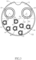
Fig. 3 is an enlarged front view of the electrical connector inFig. 1 , showing arrangement of terminals of the electrical connector; -
Fig. 4 is a partially exploded perspective view of the electrical connector inFig. 1 ; and -
Fig. 5 is a cross-sectional side view of the electrical connector along line 5-5 inFig. 1 . - With reference to
Fig. 1 , an electrical connector in accordance with the present invention has abase 30, afirst power terminal 10, asecond power terminal 20, and multiple signal terminals 41-47. Thebase 30 has arecession 31 and a connectingportion 32 disposed within therecession 31. Therecession 31 and the connectingportion 32 correspond in shape. In the present invention, therecession 31 is circular in cross-section and the connectingportion 32 is a round pillar. The connectingportion 32 extends upward from a bottom of therecession 31 coaxially. A gap is formed between an inner side surface defined around therecession 31 and a peripheral surface of the connectingportion 32 and turns into an annular space. - With reference to
Figs. 2 and3 , the connectingportion 32 has a flat face divided into afirst region 321 and asecond region 322. Thefirst power terminal 10 and thesecond terminal 20 are arranged in thefirst region 321. Themultiple signal terminals 41 to 47 are arranged in thesecond region 322. In the present invention, the connectingportion 32 is a round pillar, and the flat face of the connectingportion 32 is circular and is equally divided into thefirst region 321 and thesecond region 322 by 180 degrees. InFig. 3 , a semi-circle above a dividing line extending toward 90 degrees and 270 degrees is defined as thefirst region 321, and the other semi-circle below the dividing line at 90 degrees and 270 degrees is defined as thesecond region 322. The connectingportion 32 is a round pillar, and thefirst region 321 and thesecond region 322 being symmetrical semi-circles are merely for illustration. The shapes of the connectingportion 32, thefirst region 321, and thesecond region 322 are not restricted. - In the present invention, the
first power terminal 10 is a negative terminal and thesecond power terminal 20 is a positive terminal for compliance with safety requirements of common electrical connectors such as requirement of withstand voltage or requirement of insulation resistance. A substantially large distance remaining between thefirst power terminal 10 and thesecond power terminal 20 is in thefirst region 321. Specifically, the distance between thefirst power terminal 10 and thesecond power terminal 20 is larger than a distance between each two of the signal terminals 41-47 that are disposed adjacent to each other. The distance between thefirst power terminal 10 and thesecond power terminal 20 is also larger than a distance between thefirst power terminal 10 and each one of the signal terminals 41-47. The distance between thefirst power terminal 10 and thesecond power terminal 20 is larger than a distance between thesecond power terminal 20 and each one the signal terminals 41-47 as well. - In the present invention, the signal terminals 41-47 are disposed within the
second region 322 of the connectingportion 32. Functions of pins of the signal terminals 41-47 are defined in the table listed below, which are charging detection (Charge DET), not available (N/A), confirmation of batteries communication (Cable DET), batteries awaking (Wake up), low-voltage bus signal (CAN L), high-voltage bus signal (CAN H), and terminal test (Terminal DET).Numbering of signal terminal Function of pin of signal terminal 41 Charge DET 42 N/ A 43 Cable DET 44 Wake up 45 CAN L 46 CAN H 47 Terminal DET - Moreover, in the signal terminals 41-47, the signal terminals 41-44 for charging detection (Charge DET), not available (N/A), confirmation of batteries communication (Cable DET), and batteries awaking (Wake up) are arranged at a border of the
first region 321. Wherein thesignal terminal 41 for charging detection (Charge DET) and thesignal terminal 42 not available (N/A) are adjacent to thefirst power terminal 10. Thesignal terminal 41 for charging detection (Charge DET) and thefirst power terminal 10 have a first distance D1 therebetween. Thesignal terminal 42 not available (N/A) and thefirst power terminal 10 have the same first distance D1 therebetween. Furthermore, thesignal terminal 42 not available (N/A), thesignal terminal 43 for confirmation of batteries communication (Cable DET), and thesignal terminal 44 for batteries awaking (Wake up) are adjacent to thesecond power terminal 20. Thesignal terminal 42 not available (N/A) and thesecond power terminal 20 have a second distance D2. Thesignal terminal 43 for confirmation of batteries communication (Cable DET) and thesecond power terminal 20 have the same second distance D2. Thesignal terminal 44 for batteries awaking (Wake up) and thesecond power terminal 20 have the same distance D2. Each second distance D2 is larger than each first distance D1. - Since the
first power terminal 10 is a negative terminal, signal transmission of thesignal terminal 42 not available (N/A) or thesignal terminal 43 for confirmation of batteries communication (Cable DET) is free from interference by thefirst power terminal 10. Therefore, the first distance D1 may be designed as a short distance. Signal transmission of thesignal terminal 42 not available (N/A), thesignal terminal 43 for confirmation of batteries communication (Cable DET), or thesignal terminal 44 for batteries awaking (Wake up) may be interfered by thesecond power terminal 20, which is a positive terminal when thesecond power terminal 20 is charging. Therefore, thesignal terminal 42 not available (N/A), thesignal terminal 43 for confirmation of batteries communication (Cable DET), and thesignal terminal 44 for batteries awaking (Wake up) respectively have to maintain a certain distance such as the second distance D2 that is larger than the first distance D1. - In order to prevent signal transmission of the signal terminals 41-47 from being interfered by the
second power terminal 20 during charging, thesignal terminal 45 for low-voltage bus signal (CAN L), thesignal terminal 46 for high-voltage bus signal (CAN H), and thesignal terminal 47 for terminal test (Terminal DET) always in a status of signal transmission are disposed within thesecond region 322 and away from thefirst region 321 to keep a relative far distance from thesecond power terminal 20 to make sure the signal terminals 45-47 are free from interfering by thesecond power terminal 20. - With regard to assembly of the
first power terminal 10, thesecond power terminal 20, and the signal terminals 41-47 to the connectingportion 32 of thebase 30, please further refer toFig. 4 . Thefirst power terminal 10 and thesecond power terminal 20 are axially embedded in the connectingportion 32 of thebase 30. Specifically, thefirst power terminal 10 and thesecond power terminal 20 are inserted into a core in advance for production when thebase 30 is molded. Thefirst power terminal 10 and thesecond power terminal 20 are simultaneously assembled to the connectingportion 32 of the base 30 after thebase 30 is molded. - With reference to
Fig. 5 , thefirst power terminal 10 and thesecond power terminal 20 each have a respective end being adjacent to the flat face of the connectingportion 32 and being hollow to form an inserting hole. Thefirst power terminal 10 and thesecond power terminal 20 each have another respective end exposed at a bottom of thebase 30 of the electrical connector of the present invention. In order to provide stable electrical connection, there are twoelastic connectors first power terminal 10 and thesecond power terminal 20. Eachelastic connector 11/21 has multiple connecting points for electrical connection. The twoelastic connectors first power terminal 10 and thesecond power terminal 20. The twoelastic connectors elastic connectors - In addition, the signal terminals 41-47 are assembled to the connecting
portion 32 of thebase 30. The connectingportion 32 hasterminal recessions 323 respectively for assembling the signal terminals 41-47. One of two ends of eachterminal recession 323 is defined through the flat face of the connectingportion 32, and the other one of the two ends of eachterminal recession 323 is defined through the bottom of the base 30 to form a pin hole. For example, thesignal terminal 45 has acontact 451 being tubular and anarrow pin 452 respectively disposed at two ends of thesignal terminal 45. Thecontact 451 is disposed within one of theterminal recessions 323, and thenarrow pin 452 extends out from theterminal recession 323 for exterior connection. - With reference to
Figs. 2 and4 , thebase 30 has a top end and a fixingportion 33 disposed at the top end of thebase 30 and outward expands along radial directions of therecession 31. The fixingportion 33 is provided with connection of the electrical connector of the present invention. In the present invention, the fixingportion 33 is rectangular and has a fixinghole 330 formed at each corner of the fixingportion 33 to accommodate other fixing units for fixation. - As stated above, the present invention provides the electrical connector for transmitting electrical power and signals. Power terminals and signal terminals of the electrical connector of the present invention are arranged at different regions by space planning. Terminals for same or similar energy type are arranged at a same region. In addition, with respect to efficient space utilization, distances between the signal terminal and the power terminal are further designed according to signal properties. Therefore, the electrical connector of the present invention can ensure that the power terminals and the signal terminals are free from interfering during power and signal transmission. The electrical connector of the present invention complies with safety requirements of common electrical connectors such as requirement of withstand voltage or requirement of insulation.
Claims (10)
- An electrical connector, characterized in that the electrical connector comprises:a base (30) having
a connecting portion (32) having a flat face divided into a first region (321) and a second region (322);two power terminals including a first power terminal (10) and a second power terminal (20), and the first power terminal (10) and the second power terminal (20) disposed at the connecting portion (32) and within the first region (321); andmultiple signal terminals (41-47) disposed at the connecting portion (32) and within the second region (322), whereinat least one of the multiple signal terminals (41-47) is apart from the first power terminal (10) by a first distance (D1);at least one of the other multiple signal terminals (41-47) is apart from the second power terminal (20) by a second distance (D2); andthe second distance (D2) is larger than the first distance (D1). - The electrical connector as claimed in claim 1, whereina distance defined between the first power terminal (10) and the second power terminal (20) is larger than a distance defined between each two of the multiple signal terminals (41-47) that are disposed adjacent to each other;the distance defined between the first power terminal (10) and the second power terminal (20) is larger than a distance defined between each one of the multiple signal terminals (41-47) and the first power terminal (10); andthe distance defined between the first power terminal (10) and the second power terminal (20) is larger than a distance defined between each one of the multiple signal terminals (41-47) and the second power terminal (20).
- The electrical connector as claimed in claim 1, whereinthree of the multiple signal terminals (41, 43, 44) are respectively for charging detection (Charge DET), confirmation of batteries communication (Cable DET), and batteries awaking (Wake up) and are arranged within the second region (322) and are disposed adjacent to a border between the first region (321) and the second region (322);the signal terminal (43) for charging detection (Charge DET) is apart from the first power terminal (10) by the first distance (D1); andthe other two signal terminals (43, 44) respectively for confirmation of batteries communication (Cable DET) and batteries awaking (Wake up) are each apart from the second power terminal (20) by the second distance (D2).
- The electrical connector as claimed in claim 3, wherein three of the multiple signal terminals (45, 46, 47) are respectively for low-voltage bus signal (CAN L), high-voltage bus signal (CAN H), and terminal test (Terminal DET) and are disposed within the second region (322) and away from the first region (321).
- The electrical connector as claimed in claim 3, wherein one of the multiple signal terminals (42) is for not available (N/A), is disposed within the second region (322) and adjacent to the border between the first region (321) and the second region (322), is apart from the first power terminal (10) by the first distance (D1), and is apart from the second power terminal (20) by the second distance (D2).
- The electrical connector as claimed in any one of claims 1 to 5, wherein the connecting portion (32) is a round pillar and has the flat face being circular and divided into two semi-circles which are respectively the first region (321) and the second region (322).
- The electrical connector as claimed in claim 6, whereinthe base (30) has a recession (31) being circular in cross-section;the connecting portion (32) is disposed within the recession (31) and extends upward from a bottom of the recession (31); andan annular space is formed between an inner side surface defined around the recession (31) and a peripheral surface of the connecting portion (32).
- The electrical connector as claimed in claim 6, whereinone of two ends of each one of the first power terminal (10) and the second power terminal (20) is disposed adjacent to the flat face of the connecting portion (32), is hollow, and is formed as an inserting hole; andthe other one of the two ends of each one of the first power terminal (10) and the second power terminal (20) is exposed at a bottom of the base (30);wherein an elastic connector (11, 21) is disposed within the inserting hole of each one of the first power terminal (10) and the second power terminal (20) and has multiple connecting points.
- The electrical connector as claimed in claim 8, wherein the elastic connector (11, 21) is a crown spring connector.
- The electrical connector as claimed in claim 6, whereinmultiple terminal recessions (323) are formed in the connecting portion (32);one of two ends of each one of the terminal recessions (323) is defined through the flat face of the connecting portion (32), and the other one of the two ends of each one of the terminal recessions (323) is defined through a bottom of the base (30) to form a pin hole; andone of two ends of each one of the multiple signal terminals (41-47) is a contact (451) being tubular, and the other one of two ends of each one of multiple signal terminals (41-47) is a narrow pin (452);wherein the contact (451) of each of the multiple signal terminals (41-47) is disposed within a respective one of the terminal recessions (323), and the narrow pin (452) of each of the multiple signal terminals (41-47) extends out from the pin hole.
Applications Claiming Priority (1)
| Application Number | Priority Date | Filing Date | Title |
|---|---|---|---|
| TW110132887A TWI784701B (en) | 2021-09-03 | 2021-09-03 | Electrical connectors for power and signal transmission |
Publications (1)
| Publication Number | Publication Date |
|---|---|
| EP4144572A1 true EP4144572A1 (en) | 2023-03-08 |
Family
ID=78822234
Family Applications (1)
| Application Number | Title | Priority Date | Filing Date |
|---|---|---|---|
| EP21212751.8A Pending EP4144572A1 (en) | 2021-09-03 | 2021-12-07 | Electrical connector for an electric vehicle having power and signal terminals |
Country Status (3)
| Country | Link |
|---|---|
| US (1) | US11897351B2 (en) |
| EP (1) | EP4144572A1 (en) |
| TW (1) | TWI784701B (en) |
Cited By (1)
| Publication number | Priority date | Publication date | Assignee | Title |
|---|---|---|---|---|
| US11897351B2 (en) * | 2021-09-03 | 2024-02-13 | T-Conn Precision Corporation | Electrical connector |
Families Citing this family (2)
| Publication number | Priority date | Publication date | Assignee | Title |
|---|---|---|---|---|
| TWI840697B (en) * | 2021-08-27 | 2024-05-01 | 太康精密股份有限公司 | Charging connector |
| USD1068684S1 (en) * | 2023-03-16 | 2025-04-01 | Winchester Interconnect | Connector |
Citations (5)
| Publication number | Priority date | Publication date | Assignee | Title |
|---|---|---|---|---|
| EP2942843A1 (en) * | 2013-03-19 | 2015-11-11 | Sumitomo Wiring Systems, Ltd. | Vehicle-side connector |
| EP3139452A1 (en) * | 2015-09-02 | 2017-03-08 | Japan Aviation Electronics Industry, Ltd. | Connector and connector assembly |
| EP3331099A1 (en) * | 2015-12-25 | 2018-06-06 | Fujikura Ltd. | Charging connector and charging connector assembly production method |
| US20200227868A1 (en) * | 2019-01-15 | 2020-07-16 | Honda Motor Co.,Ltd. | Connector device and connector connection determination device |
| EP3819997A1 (en) * | 2019-11-07 | 2021-05-12 | Delta Electronics, Inc. | Adapter assembly |
Family Cites Families (25)
| Publication number | Priority date | Publication date | Assignee | Title |
|---|---|---|---|---|
| WO2008109109A1 (en) * | 2007-03-06 | 2008-09-12 | Tyco Electronics Corporation | High voltage shielded electrical connector assembly |
| US8075329B1 (en) * | 2010-06-08 | 2011-12-13 | Ford Global Technologies, Llc | Method and system for preventing disengagement between an electrical plug and a charge port on an electric vehicle |
| JP2014519685A (en) * | 2011-05-31 | 2014-08-14 | コリア・エレクトリック・ターミナル・コーポレイション・リミテッド | Charging connector latching device |
| JP5822047B2 (en) * | 2013-03-19 | 2015-11-24 | 住友電装株式会社 | Vehicle side connector |
| CN105144498B (en) * | 2013-03-19 | 2017-10-13 | 住友电装株式会社 | Vehicle side connector |
| KR101473486B1 (en) * | 2013-09-09 | 2014-12-16 | 한국단자공업 주식회사 | Connector for charging |
| KR102107250B1 (en) * | 2014-04-14 | 2020-05-06 | 엘에스이브이코리아 주식회사 | Service Plug Unit, Device Unit And Power Disconnecting System For Electric Automobile Having The Same |
| JP6281820B2 (en) * | 2014-04-14 | 2018-02-21 | パナソニックIpマネジメント株式会社 | Charging connector |
| FR3043602B1 (en) * | 2015-11-16 | 2018-09-21 | Bluebus | ELECTRICAL PLUG AND PLUG FOR RECHARGING AN ELECTRIC VEHICLE. |
| CN105826762B (en) * | 2016-05-03 | 2019-03-26 | 深圳市威华信新能源电气科技有限公司 | A car charging socket |
| DE102016220900B4 (en) * | 2016-10-25 | 2022-06-02 | Yazaki Corporation | locking device |
| CN207052804U (en) * | 2017-04-27 | 2018-02-27 | 泰科电子(上海)有限公司 | Terminal support seat, connector shell and electric connector |
| DE102017122490A1 (en) * | 2017-09-27 | 2019-03-28 | Phoenix Contact E-Mobility Gmbh | Charging plug system for an industrial truck |
| TWM566934U (en) * | 2018-03-26 | 2018-09-11 | 驊陞科技股份有限公司 | Electrical connector |
| CN108832345A (en) * | 2018-06-20 | 2018-11-16 | 苏州正耀电子有限公司 | Pin connector and connector assembly |
| CN208445081U (en) * | 2018-06-22 | 2019-01-29 | 苏州智绿环保科技有限公司 | New energy vehicle charging plug and charging gun |
| CN213366933U (en) * | 2020-11-11 | 2021-06-04 | 深圳灵科技术有限公司 | Quick-locking type electric connector |
| JP7543996B2 (en) * | 2021-07-29 | 2024-09-03 | 住友電装株式会社 | Charging connector |
| JP7615946B2 (en) * | 2021-07-29 | 2025-01-17 | 住友電装株式会社 | Charging connector |
| WO2023008040A1 (en) * | 2021-07-29 | 2023-02-02 | 住友電装株式会社 | Charging connector |
| JP7540404B2 (en) * | 2021-07-29 | 2024-08-27 | 住友電装株式会社 | Charging connector |
| TWI784701B (en) * | 2021-09-03 | 2022-11-21 | 太康精密股份有限公司 | Electrical connectors for power and signal transmission |
| CN215955535U (en) * | 2021-09-07 | 2022-03-04 | 太康精密股份有限公司 | Electrical connectors for power and signal transmission |
| TWI790779B (en) * | 2021-10-14 | 2023-01-21 | 大陸商昆山君磊電器有限公司 | A set of cable connector for electric motor vehicle |
| CN113844294A (en) * | 2021-11-30 | 2021-12-28 | 张家港友诚新能源科技股份有限公司 | Liquid-cooled rifle head in rifle charges |
-
2021
- 2021-09-03 TW TW110132887A patent/TWI784701B/en active
- 2021-10-29 US US17/514,150 patent/US11897351B2/en active Active
- 2021-12-07 EP EP21212751.8A patent/EP4144572A1/en active Pending
Patent Citations (5)
| Publication number | Priority date | Publication date | Assignee | Title |
|---|---|---|---|---|
| EP2942843A1 (en) * | 2013-03-19 | 2015-11-11 | Sumitomo Wiring Systems, Ltd. | Vehicle-side connector |
| EP3139452A1 (en) * | 2015-09-02 | 2017-03-08 | Japan Aviation Electronics Industry, Ltd. | Connector and connector assembly |
| EP3331099A1 (en) * | 2015-12-25 | 2018-06-06 | Fujikura Ltd. | Charging connector and charging connector assembly production method |
| US20200227868A1 (en) * | 2019-01-15 | 2020-07-16 | Honda Motor Co.,Ltd. | Connector device and connector connection determination device |
| EP3819997A1 (en) * | 2019-11-07 | 2021-05-12 | Delta Electronics, Inc. | Adapter assembly |
Cited By (1)
| Publication number | Priority date | Publication date | Assignee | Title |
|---|---|---|---|---|
| US11897351B2 (en) * | 2021-09-03 | 2024-02-13 | T-Conn Precision Corporation | Electrical connector |
Also Published As
| Publication number | Publication date |
|---|---|
| US11897351B2 (en) | 2024-02-13 |
| TW202312573A (en) | 2023-03-16 |
| TWI784701B (en) | 2022-11-21 |
| US20230071830A1 (en) | 2023-03-09 |
Similar Documents
| Publication | Publication Date | Title |
|---|---|---|
| EP4144572A1 (en) | Electrical connector for an electric vehicle having power and signal terminals | |
| EP2555342B1 (en) | Movable charging connector | |
| CN208571103U (en) | A kind of universal floating formula connector | |
| CN202695898U (en) | Radio frequency adapter with floating structure | |
| CN110829100A (en) | Replacement connector | |
| CN212085334U (en) | Three-way floating mechanism and connector | |
| CN106785680B (en) | Charging seat movable connector, assembling method thereof and floating connector | |
| CN211126215U (en) | Replacement connector | |
| CN112072362A (en) | Connector with communication heavy current resistant dialing and plugging functions | |
| CN215955535U (en) | Electrical connectors for power and signal transmission | |
| CN205039368U (en) | Connector for electric vehicle and electric vehicle | |
| CN211789654U (en) | High-power battery connector and hot plug control system | |
| CN209766684U (en) | Rectangular printed board electric connector | |
| CN212209811U (en) | Charging connector and chassis charging equipment | |
| US12170425B2 (en) | Connector and connector assembly | |
| CN110492320A (en) | A kind of intelligence changes electrical interface connector | |
| CN211238739U (en) | Socket with direction-variable plug | |
| TWM620781U (en) | Electric connector for transmitting power and signal | |
| CN106785654B (en) | Connection structure, power adapter and electronic equipment | |
| CN210535961U (en) | Large-current coupler used on battery car | |
| CN203180122U (en) | Electric connector with plane contact point | |
| CN113675644A (en) | Electric connector for transmitting electric power and signal | |
| CN218975873U (en) | Quick plug aviation waterproof connector | |
| CN114639983B (en) | Electric connector with electric shock protection function | |
| CN221126917U (en) | Separated multifunctional charger |
Legal Events
| Date | Code | Title | Description |
|---|---|---|---|
| PUAI | Public reference made under article 153(3) epc to a published international application that has entered the european phase |
Free format text: ORIGINAL CODE: 0009012 |
|
| STAA | Information on the status of an ep patent application or granted ep patent |
Free format text: STATUS: THE APPLICATION HAS BEEN PUBLISHED |
|
| AK | Designated contracting states |
Kind code of ref document: A1 Designated state(s): AL AT BE BG CH CY CZ DE DK EE ES FI FR GB GR HR HU IE IS IT LI LT LU LV MC MK MT NL NO PL PT RO RS SE SI SK SM TR |
|
| STAA | Information on the status of an ep patent application or granted ep patent |
Free format text: STATUS: REQUEST FOR EXAMINATION WAS MADE |
|
| 17P | Request for examination filed |
Effective date: 20230328 |
|
| RBV | Designated contracting states (corrected) |
Designated state(s): AL AT BE BG CH CY CZ DE DK EE ES FI FR GB GR HR HU IE IS IT LI LT LU LV MC MK MT NL NO PL PT RO RS SE SI SK SM TR |