EP4144546A1 - Vehicle towing apparatus for vehicle, and vehicle - Google Patents
Vehicle towing apparatus for vehicle, and vehicle Download PDFInfo
- Publication number
- EP4144546A1 EP4144546A1 EP21823143.9A EP21823143A EP4144546A1 EP 4144546 A1 EP4144546 A1 EP 4144546A1 EP 21823143 A EP21823143 A EP 21823143A EP 4144546 A1 EP4144546 A1 EP 4144546A1
- Authority
- EP
- European Patent Office
- Prior art keywords
- cross member
- shaped
- vehicle
- rear floor
- end portion
- Prior art date
- Legal status (The legal status is an assumption and is not a legal conclusion. Google has not performed a legal analysis and makes no representation as to the accuracy of the status listed.)
- Granted
Links
Images

Classifications
-
- B—PERFORMING OPERATIONS; TRANSPORTING
- B62—LAND VEHICLES FOR TRAVELLING OTHERWISE THAN ON RAILS
- B62D—MOTOR VEHICLES; TRAILERS
- B62D21/00—Understructures, i.e. chassis frame on which a vehicle body may be mounted
- B62D21/18—Understructures, i.e. chassis frame on which a vehicle body may be mounted characterised by the vehicle type and not provided for in groups B62D21/02 - B62D21/17
-
- B—PERFORMING OPERATIONS; TRANSPORTING
- B62—LAND VEHICLES FOR TRAVELLING OTHERWISE THAN ON RAILS
- B62D—MOTOR VEHICLES; TRAILERS
- B62D25/00—Superstructure or monocoque structure sub-units; Parts or details thereof not otherwise provided for
- B62D25/20—Floors or bottom sub-units
- B62D25/209—Arrangements for the mounting of vehicle hitches
-
- B—PERFORMING OPERATIONS; TRANSPORTING
- B60—VEHICLES IN GENERAL
- B60D—VEHICLE CONNECTIONS
- B60D1/00—Traction couplings; Hitches; Draw-gear; Towing devices
- B60D1/01—Traction couplings or hitches characterised by their type
- B60D1/04—Hook or hook-and-hasp couplings
-
- B—PERFORMING OPERATIONS; TRANSPORTING
- B60—VEHICLES IN GENERAL
- B60D—VEHICLE CONNECTIONS
- B60D1/00—Traction couplings; Hitches; Draw-gear; Towing devices
- B60D1/01—Traction couplings or hitches characterised by their type
- B60D1/06—Ball-and-socket hitches
-
- B—PERFORMING OPERATIONS; TRANSPORTING
- B60—VEHICLES IN GENERAL
- B60D—VEHICLE CONNECTIONS
- B60D1/00—Traction couplings; Hitches; Draw-gear; Towing devices
- B60D1/24—Traction couplings; Hitches; Draw-gear; Towing devices characterised by arrangements for particular functions
- B60D1/243—Traction couplings; Hitches; Draw-gear; Towing devices characterised by arrangements for particular functions for protection in case of crash, collision, impact or the like
-
- B—PERFORMING OPERATIONS; TRANSPORTING
- B60—VEHICLES IN GENERAL
- B60D—VEHICLE CONNECTIONS
- B60D1/00—Traction couplings; Hitches; Draw-gear; Towing devices
- B60D1/48—Traction couplings; Hitches; Draw-gear; Towing devices characterised by the mounting
- B60D1/485—Traction couplings; Hitches; Draw-gear; Towing devices characterised by the mounting mounted by means of transversal members attached to the frame of a vehicle
-
- B—PERFORMING OPERATIONS; TRANSPORTING
- B60—VEHICLES IN GENERAL
- B60D—VEHICLE CONNECTIONS
- B60D1/00—Traction couplings; Hitches; Draw-gear; Towing devices
- B60D1/48—Traction couplings; Hitches; Draw-gear; Towing devices characterised by the mounting
- B60D1/488—Traction couplings; Hitches; Draw-gear; Towing devices characterised by the mounting mounted directly to the chassis of the towing vehicle
-
- B—PERFORMING OPERATIONS; TRANSPORTING
- B60—VEHICLES IN GENERAL
- B60D—VEHICLE CONNECTIONS
- B60D1/00—Traction couplings; Hitches; Draw-gear; Towing devices
- B60D1/48—Traction couplings; Hitches; Draw-gear; Towing devices characterised by the mounting
- B60D1/52—Traction couplings; Hitches; Draw-gear; Towing devices characterised by the mounting removably mounted
-
- B—PERFORMING OPERATIONS; TRANSPORTING
- B60—VEHICLES IN GENERAL
- B60D—VEHICLE CONNECTIONS
- B60D1/00—Traction couplings; Hitches; Draw-gear; Towing devices
- B60D1/48—Traction couplings; Hitches; Draw-gear; Towing devices characterised by the mounting
- B60D1/56—Traction couplings; Hitches; Draw-gear; Towing devices characterised by the mounting securing to the vehicle bumper
-
- B—PERFORMING OPERATIONS; TRANSPORTING
- B60—VEHICLES IN GENERAL
- B60R—VEHICLES, VEHICLE FITTINGS, OR VEHICLE PARTS, NOT OTHERWISE PROVIDED FOR
- B60R19/00—Wheel guards; Radiator guards, e.g. grilles; Obstruction removers; Fittings damping bouncing force in collisions
- B60R19/02—Bumpers, i.e. impact receiving or absorbing members for protecting vehicles or fending off blows from other vehicles or objects
- B60R19/24—Arrangements for mounting bumpers on vehicles
- B60R19/26—Arrangements for mounting bumpers on vehicles comprising yieldable mounting means
- B60R19/34—Arrangements for mounting bumpers on vehicles comprising yieldable mounting means destroyed upon impact, e.g. one-shot type
Definitions
- the present disclosure relates to the technical field of vehicle parts, and in particular to a towing device for a vehicle and a vehicle.
- a towing device for a vehicle generally has its own cross member. Before the towing device is mounted on the vehicle, it is necessary to remove the original rear anti-collision beam and energy absorption boxes of the vehicle, and then connect the cross member of the towing device to a longitudinal member of the vehicle by means of a fastener.
- such a structure has heavy weight and large size. It generally takes a long time to mount such a structure by one person with auxiliary tools, which is difficult. Moreover, as a hard connection between the cross member of the towing device and the longitudinal member of the vehicle cannot play a role of crumpling and energy absorption, a collision force is directly transmitted to the vehicle body in case of collision. In addition, with the original rear anti-collision beam and the energy absorption boxes of the vehicle removed, the protection effect for low-speed collision is lost, and the safety performance of the vehicle for low-speed collision is reduced.
- One objective of the present disclosure is to solve the technical problem that a towing device in the prior art loses a protection effect for low-speed collision and is difficult to mount by one person due to heavy weight.
- One further objective of the present disclosure is to improve torsion resistance of the towing device, to withstand torque of a vehicle body in a width direction when a vehicle turns and a road surface is bumpy and fluctuates.
- the present disclosure provides a towing device for a vehicle.
- the vehicle includes two longitudinal members longitudinally extending along the vehicle, a rear anti-collision beam arranged on one side of the two longitudinal members and transversely extending along the vehicle, and a rear floor and a rear floor cross member that are arranged between the two longitudinal members, where an end of each of the longitudinal members close to the rear anti-collision beam is connected to the rear anti-collision beam by means of an energy absorption box.
- the towing device includes a front end portion and a rear end portion connected to the front end portion, where
- the front end portion includes a U-shaped beam, the U-shaped beam being arranged on a back surface of the rear floor.
- the U-shaped beam is provided with a first end and a second end that are oppositely arranged, and the front end portion further includes two L-shaped supports, the two L-shaped supports being both arranged on a front surface of the rear floor;
- the first end of the U-shaped beam is provided with at least one first mounting hole
- the second end of the U-shaped beam is provided with at least one second mounting hole
- one end of each of the L-shaped supports is provided with at least one third mounting hole
- each of the L-shaped supports is provided with at least one fourth mounting hole
- the towing device further includes at least one third bolt and at least one fourth bolt
- the rear floor cross member is internally provided with a cross member reinforcing plate, and the L-shaped supports penetrate the cross member reinforcing plate when being connected to the rear floor cross member.
- the connecting seat is arranged on a back surface of the rear anti-collision beam.
- the connecting seat is detachably connected to the U-shaped beam.
- the present disclosure further provides a vehicle.
- the vehicle includes the above towing device.
- a structure of the towing device is designed, the front end portion of the towing device is arranged on the rear floor and the rear floor cross member of the vehicle, and the connecting seat of the rear end portion is arranged on the rear anti-collision beam, such that the original rear anti-collision beam and energy absorption boxes of the vehicle are reserved, and during low-speed collision, the rear anti-collision beam and the energy absorption boxes may still absorb collision energy by way of deformation.
- the towing device is only provided with the front end portion and the rear end portion, compared with the solution that a towing device is provided with a cross member in the prior art, an overall weight thereof is greatly reduced, such that mounting operation by one person may be achieved.
- each of the L-shaped supports are connected to the rear floor
- the other end of each of the L-shaped supports together with the cross member reinforcing plate is connected to the rear floor cross member, and during towing, stress of the tow hook uniformly disperses a tensile force to the rear floor cross member by means of the U-shaped beam, to achieve the purpose of bearing the tensile force of a vehicle body in a length direction.
- the U-shaped beam is arranged to be U-shaped, such that connecting points on the rear floor cross member are separated by a certain distance in a width direction of the vehicle body, torsion resistance of the towing device is enhanced, and capacity of bearing torque in the width direction of the vehicle body may be achieved when the vehicle turns and a road surface is bumpy and fluctuates.
- the L-shaped supports have the effects of a reinforcing rib and a flanging and bear bending moment generated due to road bumping during towing together with the cross member reinforcing plate.
- the connecting seat is connected to the rear anti-collision beam, and a tensile force and a vertical force borne by the rear end are transmitted to the longitudinal members by means of the rear anti-collision beam and the energy absorption boxes, to satisfy a vertical carrying requirement.
- the first mounting hole, the second mounting hole, the third mounting hole and the fourth mounting hole are provided in the mode of the embodiments of the present disclosure, such that the functions of the U-shaped beam and the L-shaped supports may be further enhanced.
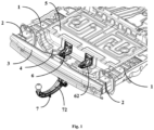
- Fig. 1 shows a front schematic structural diagram of a towing device for a vehicle according to an embodiment of the present disclosure.
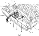
- Fig. 2 shows a back schematic structural diagram of a towing device for a vehicle according to an embodiment of the present disclosure.
- Fig. 3 shows a schematic exploded view of a towing device for a vehicle according to an embodiment of the present disclosure.
- Front surface involved below means one surface of a vehicle that may be viewed by human eyes when the vehicle is normally placed on the ground.
- “Back surface” is the other surface opposite the "front surface”.
- the vehicle includes two longitudinal members 1, two energy absorption boxes 2 arranged at ends of the two longitudinal members 1 respectively, a rear anti-collision beam 3 connected to the longitudinal members 1 by means of the energy absorption boxes 2 and transversely arranged, and a rear floor 4 and a rear floor cross member 5 which are located between the two longitudinal members 1.
- the towing device includes a front end portion 6 and a rear end portion 7 connected to the front end portion 6.
- the front end portion 6 is arranged on the rear floor 4 and the rear floor cross member 5 of the vehicle.
- the rear end portion 7 includes a connecting seat 71 and a tow hook 72 connected to the connecting seat 71 together, where the connecting seat 71 is arranged on the rear anti-collision beam 3, and the tow hook 72 extends out of the vehicle from a portion connected to the connecting seat 71.
- An external force borne by the front end portion 6 is dispersed to the rear floor cross member 5, and an external force borne by the rear end portion 7 is transmitted to the longitudinal members 1 by means of the rear anti-collision beam 3 and the energy absorption boxes 2.
- a structure of the towing device is designed, the front end portion 6 of the towing device is arranged on the rear floor 4 and the rear floor cross member 5 of the vehicle, and the connecting seat 71 of the rear end portion 7 is arranged on the rear anti-collision beam 3, such that the original rear anti-collision beam 3 and the original energy absorption boxes 2 of the vehicle are reserved, and during low-speed collision, the rear anti-collision beam 3 and the energy absorption boxes 2 may still absorb collision energy by way of deformation.
- the towing device is only provided with the front end portion 6 and the rear end portion 7, compared with the solution that a towing device is provided with a cross member in the prior art, an overall weight thereof is greatly reduced, such that mounting operation by one person may be achieved.
- the front end portion 6 includes a U-shaped beam 61 and two L-shaped supports 62.
- the U-shaped beam 61 is arranged on a back surface of the rear floor 4.
- the two L-shaped supports 62 are both arranged on a front surface of the rear floor 4.
- the U-shaped beam 61 is provided with a first end 611 and a second end 612 that are oppositely arranged.
- One end of one L-shaped support 62 is connected to the first end 611 of the U-shaped beam 61, and the other end of the one L-shaped support is connected to the rear floor cross member 5.
- One end of the other L-shaped support 62 is connected to the second end 612 of the U-shaped beam 61, and the other end of the other L-shaped support is connected to the rear floor cross member 5.
- the connecting seat 71 of the rear end portion 7 is arranged on a back surface of the rear anti-collision beam 3, and the connecting seat 71 is detachably connected to the U-shaped beam 61 together.
- the connecting seat 71 includes a connecting plate 711 and fixing frames 712 connected to the connecting plate 711 by means of a fastener.
- the connecting plate 711 is configured as a flat plate structure, and is mounted on the back surface of the rear anti-collision beam 3.
- the fixing frames 712 are L-shaped on the whole, there are two fixing frames, and the two fixing frames 712 are connected to two sides of the flat plate structure respectively and located on two sides of the tow hook 72.
- the two fixing frames 712 are both connected to the U-shaped beam 61.
- the first end 611 of the U-shaped beam 61 is provided with two first mounting holes 613
- the second end 612 of the U-shaped beam 61 is provided with two second mounting holes 614.
- the two first mounting holes 613 are arranged in a length direction of a vehicle body at the first end 611 of the U-shaped beam 61
- the two second mounting holes 614 are arranged in the length direction of the vehicle body at the second end 612 of the U-shaped beam 61.
- One end of each of the L-shaped supports 62 is provided with two third mounting holes 615.
- the other end of each of the L-shaped supports 62 is provided with two fourth mounting holes 616.
- the two third mounting holes 615 of one L-shaped support 62 are arranged in the length direction of the vehicle body and correspond to the two first mounting holes 613, so as to make one first bolt 8 of two first bolts 8 penetrate one first mounting hole 613 and the third mounting hole 615 corresponding to the one first mounting hole 613, and make the other one first bolt 8 of the two first bolts 8 penetrate the other first mounting hole 613 and the other third mounting hole 615 corresponding to the other first mounting hole 613, such that the first end 611 of the U-shaped beam 61 is connected to the one L-shaped support 62 together.
- the two third mounting holes 615 of the other L-shaped support 62 are arranged in the length direction of the vehicle body and correspond to the two second mounting holes 614, so as to make one second bolt 9 of two second bolts 9 penetrate one second mounting hole 614 and the third mounting hole 615 corresponding to the one second mounting hole 614, and make the other one first bolt 8 of the two first bolts 8 penetrate the other second mounting hole 614 and the other third mounting hole 615 corresponding to the other second mounting hole 614, such that the second end 612 of the U-shaped beam 61 is connected to the other L-shaped support 62 together.
- the two fourth mounting holes 616 of one L-shaped support 62 are arranged in a width direction of the vehicle body, one third bolt 10 of two third bolts 10 penetrate one fourth mounting hole 616 of the two fourth mounting holes 616 and the rear floor cross member 5, and the other third bolt 10 penetrates the other fourth mounting hole 616 of the one L-shaped support 62 and the rear floor cross member 5, thereby connecting the one L-shaped support 62 to the rear floor cross member 5 together.
- the two fourth mounting holes 616 of the other L-shaped support 62 are arranged in the width direction of the vehicle body, one fourth bolt 11 of two fourth bolts 11 penetrates one fourth mounting hole 616 of the two fourth mounting holes 616 and the rear floor cross member 5, and the other fourth bolt 11 penetrates the other fourth mounting hole 616 of the other L-shaped support 62 and the rear floor cross member 5, thereby connecting the other L-shaped support 62 to the rear floor cross member 5 together.
- the rear floor cross member 5 is internally provided with a cross member reinforcing plate (not shown in the figures), and the L-shaped supports 62 penetrate the cross member reinforcing plate when being connected to the rear floor cross member 5.
- the U-shaped beam 61 and one end of each of the L-shaped supports 62 are connected to the rear floor 4, the other end of each of the L-shaped supports 62 together with the cross member reinforcing plate is connected to the rear floor cross member 5, and during towing, stress of the tow hook 72 uniformly disperses a tensile force to the rear floor cross member 5 by means of the U-shaped beam 61, to achieve the purpose of bearing the tensile force in the length direction of the vehicle body.
- the U-shaped beam 61 is arranged to be U-shaped, such that connecting points on the rear floor cross member 5 are separated by a certain distance in the width direction of the vehicle body, torsion resistance of the towing device is enhanced, and capacity of bearing torque in the width direction of the vehicle body may be achieved when the vehicle turns and a road surface is bumpy and fluctuates.
- the L-shaped supports 62 have the effects of a reinforcing rib and a flanging and bear bending moment generated due to road bumping during towing together with the cross member reinforcing plate.
- the connecting seat 71 is connected to the rear anti-collision beam 3, and a tensile force and a vertical force borne by the rear end are transmitted to the longitudinal members 1 by means of the rear anti-collision beam 3 and the energy absorption boxes 2, to satisfy a vertical carrying requirement.
- the first mounting holes 613, the second mounting holes 614, the third mounting holes 615 and the fourth mounting holes 616 are provided in the mode of the embodiment of the present disclosure, such that the functions of the U-shaped beam 61 and the L-shaped supports 62 may be further enhanced.
- the embodiment 3 differs from the embodiment 2 in that there are one, three or more first mounting holes 613, one, three or more second mounting holes 614, one, three or more third mounting holes 615, and one, three or more fourth mounting holes 616; there are one, three or more first bolts 8, one, three or more second bolts 9, one, three or more third bolts 10, and one, three or more fourth bolts 11; and the numbers thereof may be configured as required.
- the present disclosure further provides a vehicle.
- the vehicle includes the towing device in the above embodiments.
- the towing device of the present disclosure reduces weight of the body, improves mounting convenience, shortens mounting time, and meanwhile, reserves low-speed collision performance of the whole vehicle on the premise of satisfying towing capacity.
Landscapes
- Engineering & Computer Science (AREA)
- Mechanical Engineering (AREA)
- Transportation (AREA)
- Chemical & Material Sciences (AREA)
- Combustion & Propulsion (AREA)
- Body Structure For Vehicles (AREA)
Abstract
Description
- The present disclosure relates to the technical field of vehicle parts, and in particular to a towing device for a vehicle and a vehicle.
- Presently, a towing device for a vehicle generally has its own cross member. Before the towing device is mounted on the vehicle, it is necessary to remove the original rear anti-collision beam and energy absorption boxes of the vehicle, and then connect the cross member of the towing device to a longitudinal member of the vehicle by means of a fastener.
- With the cross member, such a structure has heavy weight and large size. It generally takes a long time to mount such a structure by one person with auxiliary tools, which is difficult. Moreover, as a hard connection between the cross member of the towing device and the longitudinal member of the vehicle cannot play a role of crumpling and energy absorption, a collision force is directly transmitted to the vehicle body in case of collision. In addition, with the original rear anti-collision beam and the energy absorption boxes of the vehicle removed, the protection effect for low-speed collision is lost, and the safety performance of the vehicle for low-speed collision is reduced.
- One objective of the present disclosure is to solve the technical problem that a towing device in the prior art loses a protection effect for low-speed collision and is difficult to mount by one person due to heavy weight.
- One further objective of the present disclosure is to improve torsion resistance of the towing device, to withstand torque of a vehicle body in a width direction when a vehicle turns and a road surface is bumpy and fluctuates.
- Particularly, the present disclosure provides a towing device for a vehicle. The vehicle includes two longitudinal members longitudinally extending along the vehicle, a rear anti-collision beam arranged on one side of the two longitudinal members and transversely extending along the vehicle, and a rear floor and a rear floor cross member that are arranged between the two longitudinal members, where an end of each of the longitudinal members close to the rear anti-collision beam is connected to the rear anti-collision beam by means of an energy absorption box.
- The towing device includes a front end portion and a rear end portion connected to the front end portion, where
- the front end portion is arranged on the rear floor and the rear floor cross member, so as to disperse an external force borne by the front end portion to the rear floor cross member, and
- the rear end portion includes a connecting seat and a tow hook connected to the connecting seat and extending out towards an exterior of the vehicle, the connecting seat being arranged on the rear anti-collision beam, so as to transmit an external force borne by the rear end portion to the longitudinal members by means of the rear anti-collision beam and the energy absorption boxes.
- Optionally, the front end portion includes a U-shaped beam, the U-shaped beam being arranged on a back surface of the rear floor.
- Optionally, the U-shaped beam is provided with a first end and a second end that are oppositely arranged, and the front end portion further includes two L-shaped supports, the two L-shaped supports being both arranged on a front surface of the rear floor;
- one end of one L-shaped support being connected to the first end of the U-shaped beam, and the other end of the one L-shaped support being connected to the rear floor cross member; and
- one end of the other L-shaped support being connected to the second end of the U-shaped beam, and the other end of the other L-shaped support being connected to the rear floor cross member.
- Optionally, the first end of the U-shaped beam is provided with at least one first mounting hole, the second end of the U-shaped beam is provided with at least one second mounting hole, and one end of each of the L-shaped supports is provided with at least one third mounting hole; and
- the towing device further includes at least one first bolt and at least one second bolt, the first bolt penetrating the first mounting hole of the first end and the third mounting hole of one L-shaped support, to connect the U-shaped beam and the one L-shaped support together, and
- the second bolt penetrating the second mounting hole of the second end and the third mounting hole of the other L-shaped support, to connect the U-shaped beam and the other L-shaped support together.
- Optionally, the other end of each of the L-shaped supports is provided with at least one fourth mounting hole, and the towing device further includes at least one third bolt and at least one fourth bolt,
- the third bolt penetrating one L-shaped support and the rear floor cross member, to connect the one L-shaped support and the rear floor cross member together, and
- the fourth bolt penetrating the other L-shaped support and the rear floor cross member, to connect the other L-shaped support and the rear floor cross member together.
- Optionally, the rear floor cross member is internally provided with a cross member reinforcing plate, and the L-shaped supports penetrate the cross member reinforcing plate when being connected to the rear floor cross member.
- Optionally, the connecting seat is arranged on a back surface of the rear anti-collision beam.
- Optionally, the connecting seat is detachably connected to the U-shaped beam.
- Particularly, the present disclosure further provides a vehicle. The vehicle includes the above towing device.
- According to the solution of the embodiments of the present disclosure, a structure of the towing device is designed, the front end portion of the towing device is arranged on the rear floor and the rear floor cross member of the vehicle, and the connecting seat of the rear end portion is arranged on the rear anti-collision beam, such that the original rear anti-collision beam and energy absorption boxes of the vehicle are reserved, and during low-speed collision, the rear anti-collision beam and the energy absorption boxes may still absorb collision energy by way of deformation. In addition, since the towing device is only provided with the front end portion and the rear end portion, compared with the solution that a towing device is provided with a cross member in the prior art, an overall weight thereof is greatly reduced, such that mounting operation by one person may be achieved.
- In addition, the U-shaped beam and one end of each of the L-shaped supports are connected to the rear floor, the other end of each of the L-shaped supports together with the cross member reinforcing plate is connected to the rear floor cross member, and during towing, stress of the tow hook uniformly disperses a tensile force to the rear floor cross member by means of the U-shaped beam, to achieve the purpose of bearing the tensile force of a vehicle body in a length direction.
- Moreover, the U-shaped beam is arranged to be U-shaped, such that connecting points on the rear floor cross member are separated by a certain distance in a width direction of the vehicle body, torsion resistance of the towing device is enhanced, and capacity of bearing torque in the width direction of the vehicle body may be achieved when the vehicle turns and a road surface is bumpy and fluctuates. The L-shaped supports have the effects of a reinforcing rib and a flanging and bear bending moment generated due to road bumping during towing together with the cross member reinforcing plate.
- At a rear end of the towing device, the connecting seat is connected to the rear anti-collision beam, and a tensile force and a vertical force borne by the rear end are transmitted to the longitudinal members by means of the rear anti-collision beam and the energy absorption boxes, to satisfy a vertical carrying requirement. The first mounting hole, the second mounting hole, the third mounting hole and the fourth mounting hole are provided in the mode of the embodiments of the present disclosure, such that the functions of the U-shaped beam and the L-shaped supports may be further enhanced.
- With reference to the detailed description of the specific embodiments of the present disclosure in combination with the accompanying drawings below, the above and other objectives, advantages and features of the present disclosure will become more apparent to those skilled in the art.
- Some specific embodiments of the present disclosure will be described in details in an illustrative way rather than a limiting way below with reference to the accompanying drawings. The same reference numerals in the accompanying drawings indicate the same or similar components or portions. Those skilled in the art should understand that these accompanying drawings are not necessarily drawn to scale. In the figures:
-
Fig. 1 shows a front schematic structural diagram of a towing device for a vehicle according to an embodiment of the present disclosure; -
Fig. 2 shows a back schematic structural diagram of a towing device for a vehicle according to an embodiment of the present disclosure; and -
Fig. 3 shows a schematic exploded view of a towing device for a vehicle according to an embodiment of the present disclosure. - In the
figures: 1 -longitudinal member, 2-energy absorption box, 3-rear anti-collision beam, 4-rear floor, 5-rear floor cross member, 6-front end portion, 61-U-shaped beam, 61 1-first end, 612-second end, 613-first mounting hole, 614-second mounting hole, 615-third mounting hole, 616-fourth mounting hole, 62-L-shaped support, 7-rear end portion, 71-connecting seat, 711-connecting plate, 712-fixing frame, 72-tow hook, 8-first bolt, 9-second bolt, 10-third bolt and 11-fourth bolt. -
Fig. 1 shows a front schematic structural diagram of a towing device for a vehicle according to an embodiment of the present disclosure.Fig. 2 shows a back schematic structural diagram of a towing device for a vehicle according to an embodiment of the present disclosure.Fig. 3 shows a schematic exploded view of a towing device for a vehicle according to an embodiment of the present disclosure. "Front surface" involved below means one surface of a vehicle that may be viewed by human eyes when the vehicle is normally placed on the ground. "Back surface" is the other surface opposite the "front surface". - As shown in
Figs. 1-3 , the vehicle includes twolongitudinal members 1, twoenergy absorption boxes 2 arranged at ends of the twolongitudinal members 1 respectively, a rearanti-collision beam 3 connected to thelongitudinal members 1 by means of theenergy absorption boxes 2 and transversely arranged, and a rear floor 4 and a rearfloor cross member 5 which are located between the twolongitudinal members 1. The towing device includes afront end portion 6 and a rear end portion 7 connected to thefront end portion 6. Thefront end portion 6 is arranged on the rear floor 4 and the rearfloor cross member 5 of the vehicle. The rear end portion 7 includes a connectingseat 71 and atow hook 72 connected to the connectingseat 71 together, where the connectingseat 71 is arranged on the rearanti-collision beam 3, and thetow hook 72 extends out of the vehicle from a portion connected to the connectingseat 71. An external force borne by thefront end portion 6 is dispersed to the rearfloor cross member 5, and an external force borne by the rear end portion 7 is transmitted to thelongitudinal members 1 by means of the rearanti-collision beam 3 and theenergy absorption boxes 2. - According to the solution of the embodiment of the present disclosure, a structure of the towing device is designed, the
front end portion 6 of the towing device is arranged on the rear floor 4 and the rearfloor cross member 5 of the vehicle, and the connectingseat 71 of the rear end portion 7 is arranged on the rearanti-collision beam 3, such that the original rearanti-collision beam 3 and the originalenergy absorption boxes 2 of the vehicle are reserved, and during low-speed collision, the rearanti-collision beam 3 and theenergy absorption boxes 2 may still absorb collision energy by way of deformation. In addition, since the towing device is only provided with thefront end portion 6 and the rear end portion 7, compared with the solution that a towing device is provided with a cross member in the prior art, an overall weight thereof is greatly reduced, such that mounting operation by one person may be achieved. - In this embodiment, as shown in
Figs. 2 and3 , thefront end portion 6 includes aU-shaped beam 61 and two L-shaped supports 62. TheU-shaped beam 61 is arranged on a back surface of the rear floor 4. The two L-shapedsupports 62 are both arranged on a front surface of the rear floor 4. TheU-shaped beam 61 is provided with afirst end 611 and asecond end 612 that are oppositely arranged. One end of one L-shapedsupport 62 is connected to thefirst end 611 of theU-shaped beam 61, and the other end of the one L-shaped support is connected to the rearfloor cross member 5. One end of the other L-shapedsupport 62 is connected to thesecond end 612 of theU-shaped beam 61, and the other end of the other L-shaped support is connected to the rearfloor cross member 5. - The connecting
seat 71 of the rear end portion 7 is arranged on a back surface of therear anti-collision beam 3, and the connectingseat 71 is detachably connected to theU-shaped beam 61 together. The connectingseat 71 includes a connectingplate 711 and fixingframes 712 connected to the connectingplate 711 by means of a fastener. The connectingplate 711 is configured as a flat plate structure, and is mounted on the back surface of therear anti-collision beam 3. The fixing frames 712 are L-shaped on the whole, there are two fixing frames, and the two fixingframes 712 are connected to two sides of the flat plate structure respectively and located on two sides of thetow hook 72. The two fixingframes 712 are both connected to theU-shaped beam 61. - The
first end 611 of theU-shaped beam 61 is provided with two first mountingholes 613, and thesecond end 612 of theU-shaped beam 61 is provided with two second mounting holes 614. The two first mountingholes 613 are arranged in a length direction of a vehicle body at thefirst end 611 of theU-shaped beam 61, and the two second mountingholes 614 are arranged in the length direction of the vehicle body at thesecond end 612 of theU-shaped beam 61. One end of each of the L-shapedsupports 62 is provided with two third mounting holes 615. The other end of each of the L-shapedsupports 62 is provided with two fourth mounting holes 616. - The two third mounting
holes 615 of one L-shapedsupport 62 are arranged in the length direction of the vehicle body and correspond to the two first mountingholes 613, so as to make one first bolt 8 of two first bolts 8 penetrate onefirst mounting hole 613 and the third mountinghole 615 corresponding to the onefirst mounting hole 613, and make the other one first bolt 8 of the two first bolts 8 penetrate the other first mountinghole 613 and the other third mountinghole 615 corresponding to the other first mountinghole 613, such that thefirst end 611 of theU-shaped beam 61 is connected to the one L-shapedsupport 62 together. - The two third mounting
holes 615 of the other L-shapedsupport 62 are arranged in the length direction of the vehicle body and correspond to the two second mountingholes 614, so as to make one second bolt 9 of two second bolts 9 penetrate onesecond mounting hole 614 and the third mountinghole 615 corresponding to the onesecond mounting hole 614, and make the other one first bolt 8 of the two first bolts 8 penetrate the other second mountinghole 614 and the other third mountinghole 615 corresponding to the other second mountinghole 614, such that thesecond end 612 of theU-shaped beam 61 is connected to the other L-shapedsupport 62 together. - The two fourth mounting
holes 616 of one L-shapedsupport 62 are arranged in a width direction of the vehicle body, onethird bolt 10 of twothird bolts 10 penetrate onefourth mounting hole 616 of the two fourth mountingholes 616 and the rearfloor cross member 5, and the otherthird bolt 10 penetrates the other fourth mountinghole 616 of the one L-shapedsupport 62 and the rearfloor cross member 5, thereby connecting the one L-shapedsupport 62 to the rearfloor cross member 5 together. - The two fourth mounting
holes 616 of the other L-shapedsupport 62 are arranged in the width direction of the vehicle body, onefourth bolt 11 of twofourth bolts 11 penetrates onefourth mounting hole 616 of the two fourth mountingholes 616 and the rearfloor cross member 5, and the otherfourth bolt 11 penetrates the other fourth mountinghole 616 of the other L-shapedsupport 62 and the rearfloor cross member 5, thereby connecting the other L-shapedsupport 62 to the rearfloor cross member 5 together. - The rear
floor cross member 5 is internally provided with a cross member reinforcing plate (not shown in the figures), and the L-shapedsupports 62 penetrate the cross member reinforcing plate when being connected to the rearfloor cross member 5. - According to the embodiment of the present disclosure, the
U-shaped beam 61 and one end of each of the L-shapedsupports 62 are connected to the rear floor 4, the other end of each of the L-shapedsupports 62 together with the cross member reinforcing plate is connected to the rearfloor cross member 5, and during towing, stress of thetow hook 72 uniformly disperses a tensile force to the rearfloor cross member 5 by means of theU-shaped beam 61, to achieve the purpose of bearing the tensile force in the length direction of the vehicle body. - Moreover, the
U-shaped beam 61 is arranged to be U-shaped, such that connecting points on the rearfloor cross member 5 are separated by a certain distance in the width direction of the vehicle body, torsion resistance of the towing device is enhanced, and capacity of bearing torque in the width direction of the vehicle body may be achieved when the vehicle turns and a road surface is bumpy and fluctuates. The L-shapedsupports 62 have the effects of a reinforcing rib and a flanging and bear bending moment generated due to road bumping during towing together with the cross member reinforcing plate. - In addition, at a rear end of the towing device, the connecting
seat 71 is connected to therear anti-collision beam 3, and a tensile force and a vertical force borne by the rear end are transmitted to thelongitudinal members 1 by means of therear anti-collision beam 3 and theenergy absorption boxes 2, to satisfy a vertical carrying requirement. The first mountingholes 613, the second mountingholes 614, the third mountingholes 615 and the fourth mountingholes 616 are provided in the mode of the embodiment of the present disclosure, such that the functions of theU-shaped beam 61 and the L-shapedsupports 62 may be further enhanced. - The
embodiment 3 differs from theembodiment 2 in that there are one, three or more first mountingholes 613, one, three or more second mountingholes 614, one, three or more third mountingholes 615, and one, three or more fourth mountingholes 616; there are one, three or more first bolts 8, one, three or more second bolts 9, one, three or morethird bolts 10, and one, three or morefourth bolts 11; and the numbers thereof may be configured as required. - Particularly, the present disclosure further provides a vehicle. The vehicle includes the towing device in the above embodiments.
- Compared with a traditional towing device, the towing device of the present disclosure reduces weight of the body, improves mounting convenience, shortens mounting time, and meanwhile, reserves low-speed collision performance of the whole vehicle on the premise of satisfying towing capacity.
- So far, those skilled in the art should recognize that although a plurality of exemplary embodiments of the present disclosure have been shown and described in details herein, many other variations or modifications conforming to the principles of the present disclosure may be directly determined or derived from the contents disclosed in the present disclosure without departing from the spirit and scope of the present disclosure. Therefore, the scope of the present disclosure should be understood and deemed to cover all these other variations or modifications.
Claims (9)
- A towing device for a vehicle, the vehicle comprising two longitudinal members longitudinally extending along the vehicle, a rear anti-collision beam arranged on one side of the two longitudinal members and transversely extending along the vehicle, and a rear floor and a rear floor cross member that are arranged between the two longitudinal members, an end of each of the longitudinal members close to the rear anti-collision beam being connected to the rear anti-collision beam by means of an energy absorption box, whereinthe towing device comprises a front end portion and a rear end portion connected to the front end portion,the front end portion is arranged on the rear floor and the rear floor cross member, so as to disperse an external force borne by the front end portion to the rear floor cross member, andthe rear end portion comprises a connecting seat and a tow hook connected to the connecting seat and extending out towards an exterior of the vehicle, the connecting seat being arranged on the rear anti-collision beam, so as to transmit an external force borne by the rear end portion to the longitudinal members by means of the rear anti-collision beam and the energy absorption boxes.
- The towing device according to claim 1, wherein the front end portion comprises a U-shaped beam, the U-shaped beam being arranged on a back surface of the rear floor.
- The towing device according to claim 2, wherein the U-shaped beam is provided with a first end and a second end that are oppositely arranged, and the front end portion further comprises two L-shaped supports, the two L-shaped supports being both arranged on a front surface of the rear floor;one end of one L-shaped support being connected to the first end of the U-shaped beam, and the other end of the one L-shaped support being connected to the rear floor cross member; andone end of the other L-shaped support being connected to the second end of the U-shaped beam, and the other end of the other L-shaped support being connected to the rear floor cross member.
- The towing device according to claim 3, wherein the first end of the U-shaped beam is provided with at least one first mounting hole, the second end of the U-shaped beam is provided with at least one second mounting hole, and one end of each of the L-shaped supports is provided with at least one third mounting hole; andthe towing device further comprises at least one first bolt and at least one second bolt, the first bolt penetrating the first mounting hole of the first end and the third mounting hole of one L-shaped support, to connect the U-shaped beam and the one L-shaped support together, andthe second bolt penetrating the second mounting hole of the second end and the third mounting hole of the other L-shaped support, to connect the U-shaped beam and the other L-shaped support together.
- The towing device according to claim 4, wherein the other end of each of the L-shaped supports is provided with at least one fourth mounting hole, and the towing device further comprises at least one third bolt and at least one fourth bolt,the third bolt penetrating the fourth mounting hole of one L-shaped support and the rear floor cross member, to connect the one L-shaped support and the rear floor cross member together, andthe fourth bolt penetrating the fourth mounting hole of the other L-shaped support and the rear floor cross member, to connect the other L-shaped support and the rear floor cross member together.
- The towing device according to claim 5, wherein the rear floor cross member is internally provided with a cross member reinforcing plate, and the L-shaped supports penetrate the cross member reinforcing plate when being connected to the rear floor cross member.
- The towing device according to any one of claims 1 to 6, wherein the connecting seat is arranged on a back surface of the rear anti-collision beam.
- The towing device according to claim 7, wherein the connecting seat is detachably connected to the U-shaped beam.
- A vehicle, comprising the towing device of any one of claims 1 to 8.
Applications Claiming Priority (2)
| Application Number | Priority Date | Filing Date | Title |
|---|---|---|---|
| CN202010513485.XA CN111661161B (en) | 2020-06-08 | 2020-06-08 | Trailer device for vehicle and vehicle |
| PCT/CN2021/094888 WO2021249148A1 (en) | 2020-06-08 | 2021-05-20 | Vehicle towing apparatus for vehicle, and vehicle |
Publications (4)
| Publication Number | Publication Date |
|---|---|
| EP4144546A1 true EP4144546A1 (en) | 2023-03-08 |
| EP4144546A4 EP4144546A4 (en) | 2023-10-18 |
| EP4144546C0 EP4144546C0 (en) | 2024-07-17 |
| EP4144546B1 EP4144546B1 (en) | 2024-07-17 |
Family
ID=72385660
Family Applications (1)
| Application Number | Title | Priority Date | Filing Date |
|---|---|---|---|
| EP21823143.9A Active EP4144546B1 (en) | 2020-06-08 | 2021-05-20 | Vehicle towing apparatus for vehicle, and vehicle |
Country Status (6)
| Country | Link |
|---|---|
| US (1) | US12466222B2 (en) |
| EP (1) | EP4144546B1 (en) |
| JP (1) | JP7471464B2 (en) |
| KR (1) | KR102719312B1 (en) |
| CN (1) | CN111661161B (en) |
| WO (1) | WO2021249148A1 (en) |
Families Citing this family (9)
| Publication number | Priority date | Publication date | Assignee | Title |
|---|---|---|---|---|
| CN111661161B (en) | 2020-06-08 | 2021-06-08 | 浙江联控技术有限公司 | Trailer device for vehicle and vehicle |
| CN113246711B (en) * | 2021-06-23 | 2022-08-09 | 东风柳州汽车有限公司 | Battery package mounting structure and back floor assembly |
| JP7841864B2 (en) * | 2021-09-17 | 2026-04-07 | 株式会社Subaru | Vehicle rear structure and vehicle trailer coupling structure |
| CN114211917A (en) * | 2021-12-23 | 2022-03-22 | 奇瑞汽车股份有限公司 | Automobile towing device |
| CN114771667A (en) * | 2022-04-28 | 2022-07-22 | 重庆长安新能源汽车科技有限公司 | Automobile front assembly |
| US20240025273A1 (en) * | 2022-07-21 | 2024-01-25 | Tenneco Automotive Operating Company Inc. | Battery mounting bracket for electric vehicle battery box |
| DE102022119905A1 (en) * | 2022-08-08 | 2024-02-08 | ACPS Automotive GmbH | Trailer hitch |
| DE102022119904A1 (en) * | 2022-08-08 | 2024-02-08 | ACPS Automotive GmbH | Trailer hitch |
| CN115384242A (en) * | 2022-08-31 | 2022-11-25 | 浙江极氪智能科技有限公司 | Trailer support device and vehicle |
Family Cites Families (31)
| Publication number | Priority date | Publication date | Assignee | Title |
|---|---|---|---|---|
| US2569086A (en) * | 1949-05-20 | 1951-09-25 | Bernard A Zenk | Adjustable trailer hitch |
| US3838872A (en) | 1973-09-26 | 1974-10-01 | Reese Products | Hitch mountable to a shock absorbing bumper |
| JPS57148156A (en) | 1981-03-06 | 1982-09-13 | Nippon Denso Co | Air conditioner for vehicle |
| JPS5951603A (en) | 1982-09-17 | 1984-03-26 | Nec Corp | Microwave variable attenuator |
| JPS5951603U (en) * | 1982-09-30 | 1984-04-05 | スズキ株式会社 | Trailer hit member attachment device |
| JPS60173700A (en) | 1984-02-17 | 1985-09-07 | 株式会社ネプチユ−ン | Moving object position monitor |
| JPS6280705A (en) | 1985-10-04 | 1987-04-14 | Toshiba Corp | Adaptive control device |
| JPS6280705U (en) * | 1985-11-12 | 1987-05-23 | ||
| JPS62130906A (en) | 1985-12-03 | 1987-06-13 | Matsushita Electric Ind Co Ltd | Cassette transport device |
| JPS62130906U (en) | 1986-02-13 | 1987-08-18 | ||
| JPS6319421A (en) | 1986-07-10 | 1988-01-27 | Mitsubishi Motors Corp | Power transmission device |
| JPH0376703U (en) * | 1989-11-29 | 1991-07-31 | ||
| US5193837A (en) * | 1990-08-21 | 1993-03-16 | Trimas Corporation | Universally adjustable trailer hitch |
| US5876078A (en) * | 1997-01-21 | 1999-03-02 | Ford Global Technologies, Inc. | Bumper and front rail assembly for vehicle |
| SE517436C2 (en) | 1997-02-12 | 2002-06-04 | Saab Automobile | Towing arrangement of a motor vehicle |
| US6581955B2 (en) * | 1999-04-26 | 2003-06-24 | Ford Global Technologies, L.L.C. | Tow hitch rear bumper assembly |
| DE10235184A1 (en) | 2002-08-01 | 2004-02-19 | Bayerische Motoren Werke Ag | Vehicle module has flap movable from closed position, concealing vehicle towing device, to open position giving access to towing device and strengthening frame enclosing flap for fitting to bumper |
| JP2005231477A (en) | 2004-02-19 | 2005-09-02 | Toyota Motor Corp | Car body rear structure |
| DE102007017422A1 (en) | 2007-04-13 | 2008-10-16 | GM Global Technology Operations, Inc., Detroit | Motor vehicle i.e. car, body, has retainer formed as pre-mountable assembly with reinforcement parts and comprising support i.e. closed plate section, pointing in driving direction of vehicle, where support is guided from central connection |
| CN201415652Y (en) | 2009-04-29 | 2010-03-03 | 奇瑞汽车股份有限公司 | Rear bumper crossbeam assembly structure |
| DE102010020648A1 (en) | 2010-05-15 | 2011-11-17 | Gm Global Technology Operations Llc (N.D.Ges.D. Staates Delaware) | Trailer traction device of a passenger vehicle |
| JP6064312B2 (en) * | 2011-09-29 | 2017-01-25 | スズキ株式会社 | Vehicle structure |
| DE102011115686A1 (en) * | 2011-10-11 | 2013-04-11 | GM Global Technology Operations LLC (n. d. Gesetzen des Staates Delaware) | Towing device for motor vehicle, has plate-like base body which is fixed detachably or permanently to rear structure of motor vehicle or to rear module arranged on vehicle |
| JP5965428B2 (en) * | 2014-05-08 | 2016-08-03 | 富士重工業株式会社 | Trailer hitch structure |
| CN203902183U (en) * | 2014-05-22 | 2014-10-29 | 北汽福田汽车股份有限公司 | Vehicle and trailer coupler connecting component for same |
| US9914332B2 (en) * | 2016-06-07 | 2018-03-13 | Ford Global Technologies, Llc | Trailer hitch assembly for a vehicle |
| CN107901714A (en) * | 2017-11-09 | 2018-04-13 | 上汽通用五菱汽车股份有限公司 | Rear towing device and automobile |
| CN208198316U (en) * | 2018-03-30 | 2018-12-07 | 浙江零跑科技有限公司 | A kind of collision prevention of vehicle structure |
| CN109910804A (en) * | 2019-03-29 | 2019-06-21 | 浙江众泰汽车制造有限公司 | Back buffer beam for automobile assembly |
| CN110001319A (en) * | 2019-04-23 | 2019-07-12 | 北京长城华冠汽车科技股份有限公司 | Trailer hook assembly and vehicle with it |
| CN111661161B (en) | 2020-06-08 | 2021-06-08 | 浙江联控技术有限公司 | Trailer device for vehicle and vehicle |
-
2020
- 2020-06-08 CN CN202010513485.XA patent/CN111661161B/en active Active
-
2021
- 2021-05-20 US US18/001,168 patent/US12466222B2/en active Active
- 2021-05-20 JP JP2022574235A patent/JP7471464B2/en active Active
- 2021-05-20 KR KR1020227042416A patent/KR102719312B1/en active Active
- 2021-05-20 EP EP21823143.9A patent/EP4144546B1/en active Active
- 2021-05-20 WO PCT/CN2021/094888 patent/WO2021249148A1/en not_active Ceased
Also Published As
| Publication number | Publication date |
|---|---|
| WO2021249148A1 (en) | 2021-12-16 |
| JP2023528836A (en) | 2023-07-06 |
| EP4144546C0 (en) | 2024-07-17 |
| CN111661161A (en) | 2020-09-15 |
| KR20230006646A (en) | 2023-01-10 |
| CN111661161B (en) | 2021-06-08 |
| US12466222B2 (en) | 2025-11-11 |
| JP7471464B2 (en) | 2024-04-19 |
| EP4144546A4 (en) | 2023-10-18 |
| US20230226865A1 (en) | 2023-07-20 |
| KR102719312B1 (en) | 2024-10-18 |
| EP4144546B1 (en) | 2024-07-17 |
Similar Documents
| Publication | Publication Date | Title |
|---|---|---|
| EP4144546B1 (en) | Vehicle towing apparatus for vehicle, and vehicle | |
| US11465480B2 (en) | Vehicle | |
| EP2990307A2 (en) | Rear part structure of vehicle | |
| US5685599A (en) | Structural member of vehicle body | |
| CN113661084B (en) | Vehicle including battery protection structure | |
| US20130119704A1 (en) | Vehicle body front structure of electric vehicle | |
| JPWO2015001928A1 (en) | Auto body structure | |
| US10239559B2 (en) | Vehicle frames and methods of assembling the same | |
| JP2002053066A (en) | Mounting structure for towing hooks for vehicles | |
| CN105034723A (en) | Vehicle towing hook traction device | |
| KR20220082488A (en) | Body of vehicle | |
| JP2001171560A (en) | Mounting structure for towing hooks for vehicles | |
| CN210526649U (en) | An anti-collision energy-absorbing structure | |
| CN211809460U (en) | Front wall direct collision force transmission structure of load-bearing carbon fiber hydrogen energy automobile | |
| CN105564167A (en) | Automobile front tow hook installing structure and installing method thereof | |
| CN220163817U (en) | Rear anti-collision beam structure and vehicle | |
| US20240278840A1 (en) | Vehicle deformation structure | |
| SE1550634A1 (en) | Sub-frame method and arrangement for releasing a front section of the sub-frame | |
| CN214607739U (en) | A kind of automobile rear floor beam reinforcement mechanism | |
| CN224197716U (en) | Anti-collision beam assembly and vehicle | |
| JP5056554B2 (en) | Front structure of the car body | |
| CN216101388U (en) | Rear support hook structure and vehicle | |
| CN212605430U (en) | Carbon fiber automobile body enclose aluminum alloy joint design and hydrogen energy car before | |
| CN215204761U (en) | Battery package anticollision roof beam | |
| CN210454953U (en) | Anti-collision structure and car before car |
Legal Events
| Date | Code | Title | Description |
|---|---|---|---|
| STAA | Information on the status of an ep patent application or granted ep patent |
Free format text: STATUS: THE INTERNATIONAL PUBLICATION HAS BEEN MADE |
|
| PUAI | Public reference made under article 153(3) epc to a published international application that has entered the european phase |
Free format text: ORIGINAL CODE: 0009012 |
|
| STAA | Information on the status of an ep patent application or granted ep patent |
Free format text: STATUS: REQUEST FOR EXAMINATION WAS MADE |
|
| 17P | Request for examination filed |
Effective date: 20221128 |
|
| AK | Designated contracting states |
Kind code of ref document: A1 Designated state(s): AL AT BE BG CH CY CZ DE DK EE ES FI FR GB GR HR HU IE IS IT LI LT LU LV MC MK MT NL NO PL PT RO RS SE SI SK SM TR |
|
| DAV | Request for validation of the european patent (deleted) | ||
| DAX | Request for extension of the european patent (deleted) | ||
| STAA | Information on the status of an ep patent application or granted ep patent |
Free format text: STATUS: EXAMINATION IS IN PROGRESS |
|
| A4 | Supplementary search report drawn up and despatched |
Effective date: 20230914 |
|
| RIC1 | Information provided on ipc code assigned before grant |
Ipc: B60D 1/52 20060101ALI20230908BHEP Ipc: B62D 21/18 20060101ALI20230908BHEP Ipc: B60R 19/34 20060101ALI20230908BHEP Ipc: B60D 1/48 20060101AFI20230908BHEP |
|
| 17Q | First examination report despatched |
Effective date: 20230926 |
|
| GRAP | Despatch of communication of intention to grant a patent |
Free format text: ORIGINAL CODE: EPIDOSNIGR1 |
|
| STAA | Information on the status of an ep patent application or granted ep patent |
Free format text: STATUS: GRANT OF PATENT IS INTENDED |
|
| INTG | Intention to grant announced |
Effective date: 20240429 |
|
| GRAS | Grant fee paid |
Free format text: ORIGINAL CODE: EPIDOSNIGR3 |
|
| GRAA | (expected) grant |
Free format text: ORIGINAL CODE: 0009210 |
|
| STAA | Information on the status of an ep patent application or granted ep patent |
Free format text: STATUS: THE PATENT HAS BEEN GRANTED |
|
| AK | Designated contracting states |
Kind code of ref document: B1 Designated state(s): AL AT BE BG CH CY CZ DE DK EE ES FI FR GB GR HR HU IE IS IT LI LT LU LV MC MK MT NL NO PL PT RO RS SE SI SK SM TR |
|
| REG | Reference to a national code |
Ref country code: CH Ref legal event code: EP |
|
| REG | Reference to a national code |
Ref country code: DE Ref legal event code: R096 Ref document number: 602021015944 Country of ref document: DE |
|
| REG | Reference to a national code |
Ref country code: IE Ref legal event code: FG4D |
|
| U01 | Request for unitary effect filed |
Effective date: 20240812 |
|
| U07 | Unitary effect registered |
Designated state(s): AT BE BG DE DK EE FI FR IT LT LU LV MT NL PT RO SE SI Effective date: 20240902 |
|
| PG25 | Lapsed in a contracting state [announced via postgrant information from national office to epo] |
Ref country code: NO Free format text: LAPSE BECAUSE OF FAILURE TO SUBMIT A TRANSLATION OF THE DESCRIPTION OR TO PAY THE FEE WITHIN THE PRESCRIBED TIME-LIMIT Effective date: 20241017 |
|
| PG25 | Lapsed in a contracting state [announced via postgrant information from national office to epo] |
Ref country code: GR Free format text: LAPSE BECAUSE OF FAILURE TO SUBMIT A TRANSLATION OF THE DESCRIPTION OR TO PAY THE FEE WITHIN THE PRESCRIBED TIME-LIMIT Effective date: 20241018 Ref country code: PL Free format text: LAPSE BECAUSE OF FAILURE TO SUBMIT A TRANSLATION OF THE DESCRIPTION OR TO PAY THE FEE WITHIN THE PRESCRIBED TIME-LIMIT Effective date: 20240717 |
|
| PG25 | Lapsed in a contracting state [announced via postgrant information from national office to epo] |
Ref country code: IS Free format text: LAPSE BECAUSE OF FAILURE TO SUBMIT A TRANSLATION OF THE DESCRIPTION OR TO PAY THE FEE WITHIN THE PRESCRIBED TIME-LIMIT Effective date: 20241117 |
|
| PG25 | Lapsed in a contracting state [announced via postgrant information from national office to epo] |
Ref country code: HR Free format text: LAPSE BECAUSE OF FAILURE TO SUBMIT A TRANSLATION OF THE DESCRIPTION OR TO PAY THE FEE WITHIN THE PRESCRIBED TIME-LIMIT Effective date: 20240717 |
|
| PG25 | Lapsed in a contracting state [announced via postgrant information from national office to epo] |
Ref country code: ES Free format text: LAPSE BECAUSE OF FAILURE TO SUBMIT A TRANSLATION OF THE DESCRIPTION OR TO PAY THE FEE WITHIN THE PRESCRIBED TIME-LIMIT Effective date: 20240717 Ref country code: RS Free format text: LAPSE BECAUSE OF FAILURE TO SUBMIT A TRANSLATION OF THE DESCRIPTION OR TO PAY THE FEE WITHIN THE PRESCRIBED TIME-LIMIT Effective date: 20241017 |
|
| PG25 | Lapsed in a contracting state [announced via postgrant information from national office to epo] |
Ref country code: RS Free format text: LAPSE BECAUSE OF FAILURE TO SUBMIT A TRANSLATION OF THE DESCRIPTION OR TO PAY THE FEE WITHIN THE PRESCRIBED TIME-LIMIT Effective date: 20241017 Ref country code: PL Free format text: LAPSE BECAUSE OF FAILURE TO SUBMIT A TRANSLATION OF THE DESCRIPTION OR TO PAY THE FEE WITHIN THE PRESCRIBED TIME-LIMIT Effective date: 20240717 Ref country code: NO Free format text: LAPSE BECAUSE OF FAILURE TO SUBMIT A TRANSLATION OF THE DESCRIPTION OR TO PAY THE FEE WITHIN THE PRESCRIBED TIME-LIMIT Effective date: 20241017 Ref country code: IS Free format text: LAPSE BECAUSE OF FAILURE TO SUBMIT A TRANSLATION OF THE DESCRIPTION OR TO PAY THE FEE WITHIN THE PRESCRIBED TIME-LIMIT Effective date: 20241117 Ref country code: HR Free format text: LAPSE BECAUSE OF FAILURE TO SUBMIT A TRANSLATION OF THE DESCRIPTION OR TO PAY THE FEE WITHIN THE PRESCRIBED TIME-LIMIT Effective date: 20240717 Ref country code: GR Free format text: LAPSE BECAUSE OF FAILURE TO SUBMIT A TRANSLATION OF THE DESCRIPTION OR TO PAY THE FEE WITHIN THE PRESCRIBED TIME-LIMIT Effective date: 20241018 Ref country code: ES Free format text: LAPSE BECAUSE OF FAILURE TO SUBMIT A TRANSLATION OF THE DESCRIPTION OR TO PAY THE FEE WITHIN THE PRESCRIBED TIME-LIMIT Effective date: 20240717 |
|
| PG25 | Lapsed in a contracting state [announced via postgrant information from national office to epo] |
Ref country code: SM Free format text: LAPSE BECAUSE OF FAILURE TO SUBMIT A TRANSLATION OF THE DESCRIPTION OR TO PAY THE FEE WITHIN THE PRESCRIBED TIME-LIMIT Effective date: 20240717 |
|
| PG25 | Lapsed in a contracting state [announced via postgrant information from national office to epo] |
Ref country code: CZ Free format text: LAPSE BECAUSE OF FAILURE TO SUBMIT A TRANSLATION OF THE DESCRIPTION OR TO PAY THE FEE WITHIN THE PRESCRIBED TIME-LIMIT Effective date: 20240717 |
|
| PG25 | Lapsed in a contracting state [announced via postgrant information from national office to epo] |
Ref country code: SK Free format text: LAPSE BECAUSE OF FAILURE TO SUBMIT A TRANSLATION OF THE DESCRIPTION OR TO PAY THE FEE WITHIN THE PRESCRIBED TIME-LIMIT Effective date: 20240717 |
|
| U20 | Renewal fee for the european patent with unitary effect paid |
Year of fee payment: 5 Effective date: 20250326 |
|
| PLBE | No opposition filed within time limit |
Free format text: ORIGINAL CODE: 0009261 |
|
| STAA | Information on the status of an ep patent application or granted ep patent |
Free format text: STATUS: NO OPPOSITION FILED WITHIN TIME LIMIT |
|
| 26N | No opposition filed |
Effective date: 20250422 |
|
| REG | Reference to a national code |
Ref country code: CH Ref legal event code: H13 Free format text: ST27 STATUS EVENT CODE: U-0-0-H10-H13 (AS PROVIDED BY THE NATIONAL OFFICE) Effective date: 20251223 |
|
| PG25 | Lapsed in a contracting state [announced via postgrant information from national office to epo] |
Ref country code: CH Free format text: LAPSE BECAUSE OF NON-PAYMENT OF DUE FEES Effective date: 20250531 |
|
| PG25 | Lapsed in a contracting state [announced via postgrant information from national office to epo] |
Ref country code: MC Free format text: LAPSE BECAUSE OF FAILURE TO SUBMIT A TRANSLATION OF THE DESCRIPTION OR TO PAY THE FEE WITHIN THE PRESCRIBED TIME-LIMIT Effective date: 20240717 |
|
| U20 | Renewal fee for the european patent with unitary effect paid |
Year of fee payment: 6 Effective date: 20260303 |
|
| PGFP | Annual fee paid to national office [announced via postgrant information from national office to epo] |
Ref country code: GB Payment date: 20260316 Year of fee payment: 6 |
|
| PG25 | Lapsed in a contracting state [announced via postgrant information from national office to epo] |
Ref country code: IE Free format text: LAPSE BECAUSE OF NON-PAYMENT OF DUE FEES Effective date: 20250520 |