EP4144537A1 - Non-pneumatic tire with improved shear band - Google Patents
Non-pneumatic tire with improved shear band Download PDFInfo
- Publication number
- EP4144537A1 EP4144537A1 EP22193018.3A EP22193018A EP4144537A1 EP 4144537 A1 EP4144537 A1 EP 4144537A1 EP 22193018 A EP22193018 A EP 22193018A EP 4144537 A1 EP4144537 A1 EP 4144537A1
- Authority
- EP
- European Patent Office
- Prior art keywords
- layer
- reinforcement
- pneumatic tire
- shear
- layers
- Prior art date
- Legal status (The legal status is an assumption and is not a legal conclusion. Google has not performed a legal analysis and makes no representation as to the accuracy of the status listed.)
- Pending
Links
- 230000002787 reinforcement Effects 0.000 claims abstract description 87
- 239000004677 Nylon Substances 0.000 claims description 16
- 229920001778 nylon Polymers 0.000 claims description 16
- 239000004744 fabric Substances 0.000 claims description 12
- 229920001971 elastomer Polymers 0.000 claims description 8
- 229920000728 polyester Polymers 0.000 claims description 8
- 229910000831 Steel Inorganic materials 0.000 claims description 6
- 239000010959 steel Substances 0.000 claims description 6
- 239000004760 aramid Substances 0.000 claims description 5
- 229920003235 aromatic polyamide Polymers 0.000 claims description 5
- 239000010410 layer Substances 0.000 description 61
- 238000005452 bending Methods 0.000 description 7
- 238000012360 testing method Methods 0.000 description 5
- 238000013461 design Methods 0.000 description 3
- 230000003014 reinforcing effect Effects 0.000 description 3
- 239000011248 coating agent Substances 0.000 description 2
- 238000000576 coating method Methods 0.000 description 2
- 238000010276 construction Methods 0.000 description 2
- 239000012528 membrane Substances 0.000 description 2
- 238000005096 rolling process Methods 0.000 description 2
- 238000012546 transfer Methods 0.000 description 2
- 230000002411 adverse Effects 0.000 description 1
- 230000006835 compression Effects 0.000 description 1
- 238000007906 compression Methods 0.000 description 1
- 230000001419 dependent effect Effects 0.000 description 1
- 239000013013 elastic material Substances 0.000 description 1
- 238000012423 maintenance Methods 0.000 description 1
- 239000000463 material Substances 0.000 description 1
- 238000012544 monitoring process Methods 0.000 description 1
- 238000013001 point bending Methods 0.000 description 1
- 230000000284 resting effect Effects 0.000 description 1
- 239000002356 single layer Substances 0.000 description 1
- 239000007787 solid Substances 0.000 description 1
- 239000004753 textile Substances 0.000 description 1
- 229920002725 thermoplastic elastomer Polymers 0.000 description 1
- 238000004804 winding Methods 0.000 description 1
Images


Classifications
-
- B—PERFORMING OPERATIONS; TRANSPORTING
- B60—VEHICLES IN GENERAL
- B60C—VEHICLE TYRES; TYRE INFLATION; TYRE CHANGING; CONNECTING VALVES TO INFLATABLE ELASTIC BODIES IN GENERAL; DEVICES OR ARRANGEMENTS RELATED TO TYRES
- B60C7/00—Non-inflatable or solid tyres
- B60C7/10—Non-inflatable or solid tyres characterised by means for increasing resiliency
- B60C7/14—Non-inflatable or solid tyres characterised by means for increasing resiliency using springs
- B60C7/146—Non-inflatable or solid tyres characterised by means for increasing resiliency using springs extending substantially radially, e.g. like spokes
-
- B—PERFORMING OPERATIONS; TRANSPORTING
- B60—VEHICLES IN GENERAL
- B60C—VEHICLE TYRES; TYRE INFLATION; TYRE CHANGING; CONNECTING VALVES TO INFLATABLE ELASTIC BODIES IN GENERAL; DEVICES OR ARRANGEMENTS RELATED TO TYRES
- B60C7/00—Non-inflatable or solid tyres
- B60C7/10—Non-inflatable or solid tyres characterised by means for increasing resiliency
- B60C7/102—Tyres built-up with separate rubber parts
-
- B—PERFORMING OPERATIONS; TRANSPORTING
- B60—VEHICLES IN GENERAL
- B60C—VEHICLE TYRES; TYRE INFLATION; TYRE CHANGING; CONNECTING VALVES TO INFLATABLE ELASTIC BODIES IN GENERAL; DEVICES OR ARRANGEMENTS RELATED TO TYRES
- B60C9/00—Reinforcements or ply arrangement of pneumatic tyres
- B60C9/0007—Reinforcements made of metallic elements, e.g. cords, yarns, filaments or fibres made from metal
-
- B—PERFORMING OPERATIONS; TRANSPORTING
- B60—VEHICLES IN GENERAL
- B60C—VEHICLE TYRES; TYRE INFLATION; TYRE CHANGING; CONNECTING VALVES TO INFLATABLE ELASTIC BODIES IN GENERAL; DEVICES OR ARRANGEMENTS RELATED TO TYRES
- B60C9/00—Reinforcements or ply arrangement of pneumatic tyres
- B60C9/18—Structure or arrangement of belts or breakers, crown-reinforcing or cushioning layers
- B60C9/20—Structure or arrangement of belts or breakers, crown-reinforcing or cushioning layers built-up from rubberised plies each having all cords arranged substantially parallel
- B60C9/2003—Structure or arrangement of belts or breakers, crown-reinforcing or cushioning layers built-up from rubberised plies each having all cords arranged substantially parallel characterised by the materials of the belt cords
- B60C9/2009—Structure or arrangement of belts or breakers, crown-reinforcing or cushioning layers built-up from rubberised plies each having all cords arranged substantially parallel characterised by the materials of the belt cords comprising plies of different materials
-
- B—PERFORMING OPERATIONS; TRANSPORTING
- B60—VEHICLES IN GENERAL
- B60C—VEHICLE TYRES; TYRE INFLATION; TYRE CHANGING; CONNECTING VALVES TO INFLATABLE ELASTIC BODIES IN GENERAL; DEVICES OR ARRANGEMENTS RELATED TO TYRES
- B60C9/00—Reinforcements or ply arrangement of pneumatic tyres
- B60C9/18—Structure or arrangement of belts or breakers, crown-reinforcing or cushioning layers
- B60C2009/1871—Structure or arrangement of belts or breakers, crown-reinforcing or cushioning layers with flat cushions or shear layers between belt layers
-
- B—PERFORMING OPERATIONS; TRANSPORTING
- B60—VEHICLES IN GENERAL
- B60C—VEHICLE TYRES; TYRE INFLATION; TYRE CHANGING; CONNECTING VALVES TO INFLATABLE ELASTIC BODIES IN GENERAL; DEVICES OR ARRANGEMENTS RELATED TO TYRES
- B60C9/00—Reinforcements or ply arrangement of pneumatic tyres
- B60C9/18—Structure or arrangement of belts or breakers, crown-reinforcing or cushioning layers
- B60C9/20—Structure or arrangement of belts or breakers, crown-reinforcing or cushioning layers built-up from rubberised plies each having all cords arranged substantially parallel
- B60C2009/2012—Structure or arrangement of belts or breakers, crown-reinforcing or cushioning layers built-up from rubberised plies each having all cords arranged substantially parallel with particular configuration of the belt cords in the respective belt layers
- B60C2009/2016—Structure or arrangement of belts or breakers, crown-reinforcing or cushioning layers built-up from rubberised plies each having all cords arranged substantially parallel with particular configuration of the belt cords in the respective belt layers comprising cords at an angle of 10 to 30 degrees to the circumferential direction
Definitions
- the present invention relates generally to vehicle tires and non-pneumatic tires, and more particularly, to a shear band and non-pneumatic tire.
- the pneumatic tire has been the solution of choice for vehicular mobility for over a century.
- the pneumatic tire is a tensile structure.
- the pneumatic tire has at least four characteristics that make the pneumatic tire so dominant today.
- Pneumatic tires are efficient at carrying loads, because all of the tire structure is involved in carrying the load.
- Pneumatic tires are also desirable because they have low contact pressure, resulting in lower wear on roads due to the distribution of the load of the vehicle.
- Pneumatic tires also have low stiffness, which ensures a comfortable ride in a vehicle.
- the primary drawback to a pneumatic tire is that it requires compressed gasses. A conventional pneumatic tire is rendered useless after a complete loss of inflation pressure.
- a tire designed to operate without inflation pressure may eliminate many of the problems and compromises associated with a pneumatic tire. Neither pressure maintenance nor pressure monitoring is required. Structurally supported tires such as solid tires or other elastomeric structures to date have not provided the levels of performance required from a conventional pneumatic tire. A structurally supported tire solution that delivers pneumatic tire-like performance would be a desirous improvement.
- Non pneumatic tires are typically defined by their load carrying efficiency.
- Bottom loaders are essentially rigid structures that carry a majority of the load in the portion of the structure below the hub.
- Top loaders are designed so that all of the structure is involved in carrying the load. Top loaders thus have a higher load carrying efficiency than bottom loaders, allowing a design that has less mass.
- shear band The purpose of the shear band is to transfer the load from contact with the ground through tension in the spokes or connecting web to the hub, creating a top loading structure.
- shear band deforms its preferred form of deformation is shear over bending.
- the shear mode of deformation occurs because of the inextensible membranes located on the outer portions of the shear band.
- Prior art non-pneumatic tires typically have a shear band made from rubber materials sandwiched between at least two layers of inextensible belts or membranes.
- the disadvantage to this type of construction is that the rubber may not have sufficient shear rigidity to achieve the correct footprint geometry, which may adversely affect the ride and handling of the vehicle.
- the rolling resistance may also suffer due to the large amount of rubber.
- an improved shear band for a non-pneumatic tire is desired that has improved vehicle handling and rolling resistance.
- the invention relates to a non-pneumatic tire in accordance with claim 1.
- Equatorial Plane means a plane perpendicular to the axis of rotation of the tire passing through the centerline of the tire.
- “Inextensible” means that a given layer has an extensional stiffness greater than 172 MPa.
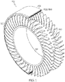
- FIG. 1 A first embodiment of a non-pneumatic tire 100 of the present invention is shown in FIG. 1 .
- the non-pneumatic tire 100 includes a radially outer ground engaging tread 200, a shear band 300, and a connecting web 500.
- the tread 200 may include elements such as ribs, blocks, lugs, grooves and sipes as desired to improve the performance of the tire in various conditions.
- the connecting web 500 is mounted on hub 512 and may have different designs, as described in more detail, below.
- the non-pneumatic tire 100 is designed to be a top loading structure, so that the shear band 300 and the connecting web 500 efficiently carry the load.
- the connecting web 500 is designed to be a stiff structure when in tension that buckles or deforms in the tire footprint and does not compress or carry a compressive load. This allows the rest of the connecting web 500 not in the footprint area the ability to carry the load, resulting in a very load efficient structure. It is desired to allow the shear band 300 to bend to overcome road obstacles.
- the approximate load distribution is preferably such that approximately 90-100% of the load is carried by the shear band 300 and the upper portion of the connecting web 500, so that the lower portion of the connecting web 500 carries virtually zero of the load, or preferably less than 10%.
- the shear band 300 is preferably an annular structure that is located radially inward of the tire tread 200 and functions to transfer the load from the bottom of the tire which is in contact with the ground to the spokes and to the hub, creating a top loading structure.
- the annular structure is called a shear band 300 because the preferred form of deformation is shear over bending.
- FIGS. 2A, 2B and FIG. 3 A first embodiment of a shear band 300 is shown in FIGS. 2A, 2B and FIG. 3 .
- the shear band 300 includes a first reinforcement layer or a first reinforcement layer group, an optional second reinforcement layer or second reinforcement layer group, and a third reinforcement layer or third reinforcement layer group third, each of which may have one or more individual reinforcement layers.
- the first layer group is shown as 320 and 330.
- the optional second reinforcement layer or layer group is shown as the single layer 360.
- the third layer group is shown as 380, 390.
- Each reinforcement layer is formed of a plurality of preferably closely spaced parallel reinforcement cords.
- the parallel reinforcement cords are preferably in the form of a calendared fabric so that the reinforcement cords are embedded in an elastomeric coating.
- each reinforcement layer 320, 330, 360, 380, 390 is formed from spirally winding a single end cord.
- the single end cord has multiple filaments.
- the reinforcing cords may be steel cords of four wires, wherein the wires preferably have a diameter in the range of from 0.1 to 0.3 mm.
- the reinforcing cords may be steel cords of 6 wires, with five wires surrounding a central wire ((5 +1)-construction), wherein the wires preferably each have a diameter in the range of from 0.1 to 0.3 mm.
- the third reinforcement layer 380, 390 is separated from the first or second reinforcement layer group 320, 330 by a first shear layer 350.
- the shear band 300 preferably further comprises a second shear layer 370 located radially outward of the second reinforcement layer group 360.
- the first and second shear layer 350, 370 are formed of one or more layers of reinforced fabric, such as nylon or polyester PET fabric.
- the nylon or polyester fabric has a plurality of parallel reinforcement cords made of nylon or polyester.
- the first and second shear layer may be formed of monofilaments of nylon that are spirally wound to form one or more reinforcement layers.
- the reinforcement layers function to increase shear rigidity.
- the shear layer 350, 370 may also be formed of a rubberized strip of one or more reinforcement cords of nylon, aramid or polyester. Each shear layer 350, 370 has one or more reinforcement layers to achieve the desired shear rigidity. As shown in FIG. 3 , each shear layer 350, 370 preferably has only minimal rubber.
- FIG. 4 illustrates an alternate shear band 301, wherein the shear layer has a layer of rubber 340 and layer of reinforcement cords as described above.
- FIG. 5 illustrates a third embodiment of a shear band 400.
- the shear band 400 has a radially inner first reinforcement layer group 410, 420, but foregoes the optional second reinforcement layer group.
- the shear band 400 further includes a radially outer third reinforcement layer group 430, 440.
- the third reinforcement layer 430 is spaced apart from the first reinforcement layer group 410, 420 by a shear layer 450.
- the reinforcement layers 410, 420, 430, 440 are preferably steel reinforcements that are preferably single end cords that are spirally wound so that the reinforcement cords align circumferentially. Preferably, they make an angle of from 5 degrees to 0 degrees with respect to the tire equatorial plane.
- the reinforcement layers 410, 420, 430, 440 may also be fabric with parallel reinforcement cords of steel or nylon or polyester.
- the reinforcement layers are for creating high bending stiffness using high modulus reinforcement cords.
- the shear layer 450 is formed of a plurality of reinforcements, preferably nylon.
- the reinforcements are preferably in the form of fabric with parallel aligned reinforcement cords, such as polyester fabric or nylon fabric.
- the reinforcements may also be formed from single end cords such as monofilament nylon that are spirally wound.
- the first, second, third and fourth reinforcement layers 410, 420, 450, 430, 440 may also comprised a tape formed of one or more reinforcement cords, wherein the tape is spirally wound to form the layers comprising the reinforcement cords.
- FIG. 6 illustrates a fourth embodiment of a shear band 600.
- the shear band 600 is the same as the shear band 400 described above, except for the following differences.
- the shear band 600 has a shear layer 610 formed of a plurality of reinforcement cords, wherein each reinforcement cord is a merged or hybrid cord 620 preferably as shown in FIGS. 7a, 7b .
- the merged cord 620 is preferably formed of three filaments, wherein the filaments are preferably nylon 630 and aramid 640 twisted together.
- the shear band 600 may have one or more layers of merged cord 620.
- the shear modulus is defined using a pure shear deformation test, recording the stress and strain, and determining the slope of the resulting stress-strain curve.
- the shear bands 300, 400, 600 may optionally include a first angled belt 380 and a second angled belt 390.
- the first angled belt 380 is located radially outward of the second shear layer 370
- the second angled belt 390 is located radially outward of the first angled belt 380.
- the first and second angled belts 380, 390 are preferably the radially outermost reinforcement layers.
- the first and second angled belts 380, 390 each have parallel reinforcement cords that are embedded in an elastomeric coating.
- the parallel reinforcement cords are preferably angled in the range of from 15 to 30 degrees with respect to the tire equatorial plane.
- the angle of the parallel reinforcement cords is in the range of from 20 to 25 degrees.
- the angle of the reinforcement cords of the first angled belt is in the opposite direction of the angle of the reinforcement cords in the second angled belt. It is additionally preferred that the reinforcement cords are inextensible.
- the shear band 300, 400, 600 has an overall shear stiffness GA or rigidity.
- the shear stiffness GA may be determined by measuring the deflection on a representative test specimen taken from the shear band. The upper surface of the test specimen is subjected to a lateral shear force F. The test specimen is a representative sample taken from the shear band and having the same radial thickness as the shear band.
- the shear band 300, 400, 600 has an overall bending stiffness El.
- the bending stiffness EI may be determined from beam mechanics using the three-point bending test. It represents the case of a beam resting on two roller supports and subjected to a concentrated load applied in the middle of the beam.
- EA is the extensible stiffness of the shear band, and it is determined experimentally by applying a tensile force and measuring the change in length.
- the ratio of the EA to EI of the shear band is acceptable in the range of 1000 to 3000, and more preferably in the range of 1500-3000.
- the non-pneumatic tire 100 further includes a connecting web 500 as shown in FIG. 1 .
- the connecting web preferably comprises a plurality of circumferentially aligned spokes 510 that extend from an inner radius to an outer radius.
- the spokes 510 are preferably oriented in the radial direction.
- the spokes 510 may be curved or straight.
- the non-pneumatic tire 100 comprises two sets of circumferentially aligned spokes 510.
- the spokes 510 may have different cross-sectional designs.
- the spokes 510 function to carry the load transmitted from the shear layer. The spokes are primarily loaded in tension and shear and carry no load in compression.
- Each spoke 510 as described herein preferably has an axial thickness A that is substantially less than the axial thickness AW of the non-pneumatic tire 100.
- the axial thickness A is preferably in the range of from 5 to 50% AW, more preferably 5-20% of AW or 5-10% of AW.
- the spokes 510 are preferably formed of an elastic material such as rubber or a thermoplastic elastomer.
- the spokes 510 are designed such that the spokes 510 have a low resistance to radial deformation and a higher resistance to the lateral deformation of the tire 100.
Abstract
Description
- The present invention relates generally to vehicle tires and non-pneumatic tires, and more particularly, to a shear band and non-pneumatic tire.
- The pneumatic tire has been the solution of choice for vehicular mobility for over a century. The pneumatic tire is a tensile structure. The pneumatic tire has at least four characteristics that make the pneumatic tire so dominant today. Pneumatic tires are efficient at carrying loads, because all of the tire structure is involved in carrying the load. Pneumatic tires are also desirable because they have low contact pressure, resulting in lower wear on roads due to the distribution of the load of the vehicle. Pneumatic tires also have low stiffness, which ensures a comfortable ride in a vehicle. The primary drawback to a pneumatic tire is that it requires compressed gasses. A conventional pneumatic tire is rendered useless after a complete loss of inflation pressure.
- A tire designed to operate without inflation pressure may eliminate many of the problems and compromises associated with a pneumatic tire. Neither pressure maintenance nor pressure monitoring is required. Structurally supported tires such as solid tires or other elastomeric structures to date have not provided the levels of performance required from a conventional pneumatic tire. A structurally supported tire solution that delivers pneumatic tire-like performance would be a desirous improvement.
- Non pneumatic tires are typically defined by their load carrying efficiency. "Bottom loaders" are essentially rigid structures that carry a majority of the load in the portion of the structure below the hub. "Top loaders" are designed so that all of the structure is involved in carrying the load. Top loaders thus have a higher load carrying efficiency than bottom loaders, allowing a design that has less mass.
- The purpose of the shear band is to transfer the load from contact with the ground through tension in the spokes or connecting web to the hub, creating a top loading structure. When the shear band deforms, its preferred form of deformation is shear over bending. The shear mode of deformation occurs because of the inextensible membranes located on the outer portions of the shear band.
- Prior art non-pneumatic tires typically have a shear band made from rubber materials sandwiched between at least two layers of inextensible belts or membranes. The disadvantage to this type of construction is that the rubber may not have sufficient shear rigidity to achieve the correct footprint geometry, which may adversely affect the ride and handling of the vehicle. In addition, the rolling resistance may also suffer due to the large amount of rubber. Thus, an improved shear band for a non-pneumatic tire is desired that has improved vehicle handling and rolling resistance.
- The invention relates to a non-pneumatic tire in accordance with claim 1.
- Dependent claims refer to preferred embodiments of the invention.
- The present invention will be better understood through reference to the following description and the appended drawings, in which:
-
FIG. 1 is a perspective view of a first embodiment of a non-pneumatic tire of the present invention; -
FIG. 2A is a cross-sectional view of a first embodiment of a shear band of the present invention, andFIG. 2B is a close-up view of the shear band ofFIG. 2A ; -
FIG. 3 is a cross-sectional view of the shear band ofFIG. 2A,2B illustrating the reinforcement layers; -
FIG. 4 is a cross-sectional view of a second embodiment of a shear band of the present invention; -
FIG. 5 is a cross-sectional view of a third embodiment of a shear band of the present invention; and -
FIG. 6 is a cross-sectional view of a fourth embodiment of a shear band of the present invention; and -
FIG. 7A is a schematic of a hybrid or merged reinforcement chord formed of nylon and aramid filaments, andFIG. 7B is a cross-sectional view of the chord ofFig. 7A . - The following terms are defined as follows for this description.
- "Equatorial Plane" means a plane perpendicular to the axis of rotation of the tire passing through the centerline of the tire.
- "Inextensible" means that a given layer has an extensional stiffness greater than 172 MPa.
- A first embodiment of a
non-pneumatic tire 100 of the present invention is shown inFIG. 1 . Thenon-pneumatic tire 100 includes a radially outerground engaging tread 200, ashear band 300, and a connectingweb 500. Thetread 200 may include elements such as ribs, blocks, lugs, grooves and sipes as desired to improve the performance of the tire in various conditions. The connectingweb 500 is mounted onhub 512 and may have different designs, as described in more detail, below. Thenon-pneumatic tire 100 is designed to be a top loading structure, so that theshear band 300 and the connectingweb 500 efficiently carry the load. The connectingweb 500 is designed to be a stiff structure when in tension that buckles or deforms in the tire footprint and does not compress or carry a compressive load. This allows the rest of the connectingweb 500 not in the footprint area the ability to carry the load, resulting in a very load efficient structure. It is desired to allow theshear band 300 to bend to overcome road obstacles. The approximate load distribution is preferably such that approximately 90-100% of the load is carried by theshear band 300 and the upper portion of the connectingweb 500, so that the lower portion of the connectingweb 500 carries virtually zero of the load, or preferably less than 10%. - The
shear band 300 is preferably an annular structure that is located radially inward of thetire tread 200 and functions to transfer the load from the bottom of the tire which is in contact with the ground to the spokes and to the hub, creating a top loading structure. The annular structure is called ashear band 300 because the preferred form of deformation is shear over bending. - A first embodiment of a
shear band 300 is shown inFIGS. 2A, 2B andFIG. 3 . Theshear band 300 includes a first reinforcement layer or a first reinforcement layer group, an optional second reinforcement layer or second reinforcement layer group, and a third reinforcement layer or third reinforcement layer group third, each of which may have one or more individual reinforcement layers. InFigure 2B , the first layer group is shown as 320 and 330. The optional second reinforcement layer or layer group is shown as thesingle layer 360. The third layer group is shown as 380, 390. Each reinforcement layer is formed of a plurality of preferably closely spaced parallel reinforcement cords. The parallel reinforcement cords are preferably in the form of a calendared fabric so that the reinforcement cords are embedded in an elastomeric coating. Preferably, eachreinforcement layer - The first
reinforcement layer group shear band 300, and the optional second reinforcement layer orlayer group 360 is located radially outward of the firstreinforcement layer group reinforcement layer group layer group 360. The preferably inextensible reinforcement cords of eachlayer - The
third reinforcement layer reinforcement layer group first shear layer 350. If the optional second reinforcement layer exists, theshear band 300 preferably further comprises asecond shear layer 370 located radially outward of the secondreinforcement layer group 360. The first andsecond shear layer shear layer shear layer FIG. 3 , eachshear layer -
FIG. 4 illustrates analternate shear band 301, wherein the shear layer has a layer ofrubber 340 and layer of reinforcement cords as described above. -
FIG. 5 illustrates a third embodiment of ashear band 400. Theshear band 400 has a radially inner first reinforcement layer group 410, 420, but foregoes the optional second reinforcement layer group. Theshear band 400 further includes a radially outer third reinforcement layer group 430, 440. The third reinforcement layer 430 is spaced apart from the first reinforcement layer group 410, 420 by a shear layer 450. The reinforcement layers 410, 420, 430, 440 are preferably steel reinforcements that are preferably single end cords that are spirally wound so that the reinforcement cords align circumferentially. Preferably, they make an angle of from 5 degrees to 0 degrees with respect to the tire equatorial plane. The reinforcement layers 410, 420, 430, 440 may also be fabric with parallel reinforcement cords of steel or nylon or polyester. The reinforcement layers are for creating high bending stiffness using high modulus reinforcement cords. The shear layer 450 is formed of a plurality of reinforcements, preferably nylon. The reinforcements are preferably in the form of fabric with parallel aligned reinforcement cords, such as polyester fabric or nylon fabric. The reinforcements may also be formed from single end cords such as monofilament nylon that are spirally wound. The first, second, third and fourth reinforcement layers 410, 420, 450, 430, 440 may also comprised a tape formed of one or more reinforcement cords, wherein the tape is spirally wound to form the layers comprising the reinforcement cords. -
FIG. 6 illustrates a fourth embodiment of ashear band 600. Theshear band 600 is the same as theshear band 400 described above, except for the following differences. Theshear band 600 has ashear layer 610 formed of a plurality of reinforcement cords, wherein each reinforcement cord is a merged orhybrid cord 620 preferably as shown inFIGS. 7a, 7b . Themerged cord 620 is preferably formed of three filaments, wherein the filaments are preferablynylon 630 andaramid 640 twisted together. Theshear band 600 may have one or more layers ofmerged cord 620. - The shear modulus is defined using a pure shear deformation test, recording the stress and strain, and determining the slope of the resulting stress-strain curve.
- The
shear bands angled belt 380 and a secondangled belt 390. The firstangled belt 380 is located radially outward of thesecond shear layer 370, and the secondangled belt 390 is located radially outward of the firstangled belt 380. The first and secondangled belts angled belts - The
shear band
GA=F*L/ΔX, where F is the shear load, L is the shear layer thickness, and delta X is the shear deflection. It is preferred that GA be I the range of from 15,000 N to 35,000N, and more preferably, about 25,000N. - The
shear band - It is desirable to maximize the bending stiffness of the shear band EI and minimize the shear band stiffness GA. The acceptable ratio of GA/EI would be between 0.01 and 20, with an ideal range between 0.01 and 5. EA is the extensible stiffness of the shear band, and it is determined experimentally by applying a tensile force and measuring the change in length. The ratio of the EA to EI of the shear band is acceptable in the range of 1000 to 3000, and more preferably in the range of 1500-3000.
- The
non-pneumatic tire 100 further includes a connectingweb 500 as shown inFIG. 1 . The connecting web preferably comprises a plurality of circumferentially alignedspokes 510 that extend from an inner radius to an outer radius. Thespokes 510 are preferably oriented in the radial direction. Thespokes 510 may be curved or straight. Preferably, thenon-pneumatic tire 100 comprises two sets of circumferentially alignedspokes 510. Thespokes 510 may have different cross-sectional designs. Thespokes 510 function to carry the load transmitted from the shear layer. The spokes are primarily loaded in tension and shear and carry no load in compression. Each spoke 510 as described herein preferably has an axial thickness A that is substantially less than the axial thickness AW of thenon-pneumatic tire 100. The axial thickness A is preferably in the range of from 5 to 50% AW, more preferably 5-20% of AW or 5-10% of AW. - The
spokes 510 are preferably formed of an elastic material such as rubber or a thermoplastic elastomer. Thespokes 510 are designed such that thespokes 510 have a low resistance to radial deformation and a higher resistance to the lateral deformation of thetire 100.
Claims (13)
- A non-pneumatic tire comprising an outer annular tread band (200), and a plurality of connecting structures (500) connecting the tread band (200) to a hub (512), wherein said outer annular tread band (200) comprises a shear band (300, 400, 600) comprising or formed of at least one first reinforcement layer (320, 330, 410, 420) located radially inward of the outer annular tread band (200) and at least one a second reinforcement layer (360, 430, 440) located radially outward of the at least one first reinforcement layer (320, 330, 410, 420), wherein the one or more first and second reinforcement layers (320, 330, 410, 420, 360, 430, 440) each comprise a plurality of parallel reinforcement cords, wherein the at least one first reinforcement layer (320, 330, 410, 420) is separated from the at least one second reinforcement layer (360, 430, 440) by a first shear layer (350, 450, 610), and wherein the first shear layer (350, 450, 610) is reinforced with reinforcements.
- The non-pneumatic tire of claim 1 wherein the reinforcement cords of the one or more first and second reinforcement layers (320, 330, 410, 420, 360, 430, 440) are arranged at an angle of 5 degrees or less with respect to the equatorial plane of the non-pneumatic tire (100).
- The non-pneumatic tire of claim 1 or 2 wherein the first shear layer (350, 450, 610) does not have a layer of rubber having a thickness in the range of from 1 to 10 mm or in the range of from 1 to 5 mm.
- The non-pneumatic tire of at least one of the previous claims wherein the first shear layer (350, 450, 610) is reinforced with one or more layers of nylon fabric or cord, one or more layers of polyester fabric or cord, one or more layers of nylon monofilament, or with one or more layers of a hybrid or merged cord, preferably a merged cord of nylon and aramid.
- The non-pneumatic tire of at least one of the previous claims wherein the first shear layer (350, 450, 610) comprises a layer of rubber.
- The non-pneumatic tire of at least one of the previous claims wherein said outer annular tread band (200) further comprises a first belt layer (380) located radially outward of the at least one a second reinforcement layer (360, 430, 440), and a second belt layer (390) located radially outward of the first angled belt (380), wherein the first and second belt layers (380, 390) each have parallel reinforcement cords making an angle in the range of from 15 to 30 degrees with respect to the equatorial plane of the non-pneumatic tire (100), and wherein the angle of the second belt layer (390) preferably makes an angle equal to but in the opposite direction of the angle of the first belt layer (380).
- The non-pneumatic tire of at least one of the previous claims wherein the one or more first and second reinforcement layers (320, 330, 410, 420, 360, 430, 440) comprise reinforcement cords arranged at an angle of zero degrees with respect to the equatorial plane of the non-pneumatic tire (100) .
- The non-pneumatic tire of at least one of the previous claims further including a further reinforcement layer comprising reinforcement cords arranged at an angle of zero degrees with respect to the tire equatorial plane.
- The non-pneumatic tire of at least one of the previous claims further including a second reinforced shear layer (370) located radially outward of the one or more second reinforcement layer (360, 430, 440).
- The non-pneumatic tire of at least one of the previous claims wherein the parallel reinforcement cords are made of steel.
- The non-pneumatic tire of at least one of the previous claims wherein the first shear layer (350, 450, 610) is formed from a plurality of layers of nylon fabric or polyester fabric.
- The non-pneumatic tire of at least one of the previous claims wherein the first shear layer (350, 450, 610) is formed from at least two layers of nylon monofilament.
- The non-pneumatic tire of at least one of the previous claims wherein the shear band (300, 400, 600) has an overall shear stiffness in the range of from 15000 N to 35000 N.
Applications Claiming Priority (2)
| Application Number | Priority Date | Filing Date | Title |
|---|---|---|---|
| US202163260815P | 2021-09-01 | 2021-09-01 | |
| US17/821,892 US20230065909A1 (en) | 2021-09-01 | 2022-08-24 | Non-pneumatic tire with improved shear band |
Publications (1)
| Publication Number | Publication Date |
|---|---|
| EP4144537A1 true EP4144537A1 (en) | 2023-03-08 |
Family
ID=83152065
Family Applications (1)
| Application Number | Title | Priority Date | Filing Date |
|---|---|---|---|
| EP22193018.3A Pending EP4144537A1 (en) | 2021-09-01 | 2022-08-30 | Non-pneumatic tire with improved shear band |
Country Status (5)
| Country | Link |
|---|---|
| US (1) | US20230065909A1 (en) |
| EP (1) | EP4144537A1 (en) |
| JP (1) | JP2023037610A (en) |
| KR (1) | KR20230033626A (en) |
| CN (1) | CN115723481A (en) |
Citations (4)
| Publication number | Priority date | Publication date | Assignee | Title |
|---|---|---|---|---|
| WO2017184237A1 (en) * | 2016-04-19 | 2017-10-26 | Bridgestone Americas Tire Operations, Llc | Tire with electronic device having a reinforcing cord antenna |
| EP3323635A1 (en) * | 2016-11-22 | 2018-05-23 | The Goodyear Tire & Rubber Company | Shear band for a structurally supported tire |
| EP3835086A1 (en) * | 2019-12-12 | 2021-06-16 | The Goodyear Tire & Rubber Company | Belt structure for a tire |
| EP3835084A1 (en) * | 2019-12-10 | 2021-06-16 | The Goodyear Tire & Rubber Company | Shear belt package for a tire and method of manufacturing |
-
2022
- 2022-08-24 US US17/821,892 patent/US20230065909A1/en active Pending
- 2022-08-30 EP EP22193018.3A patent/EP4144537A1/en active Pending
- 2022-08-31 KR KR1020220110157A patent/KR20230033626A/en not_active Application Discontinuation
- 2022-09-01 CN CN202211062636.XA patent/CN115723481A/en active Pending
- 2022-09-01 JP JP2022139363A patent/JP2023037610A/en active Pending
Patent Citations (4)
| Publication number | Priority date | Publication date | Assignee | Title |
|---|---|---|---|---|
| WO2017184237A1 (en) * | 2016-04-19 | 2017-10-26 | Bridgestone Americas Tire Operations, Llc | Tire with electronic device having a reinforcing cord antenna |
| EP3323635A1 (en) * | 2016-11-22 | 2018-05-23 | The Goodyear Tire & Rubber Company | Shear band for a structurally supported tire |
| EP3835084A1 (en) * | 2019-12-10 | 2021-06-16 | The Goodyear Tire & Rubber Company | Shear belt package for a tire and method of manufacturing |
| EP3835086A1 (en) * | 2019-12-12 | 2021-06-16 | The Goodyear Tire & Rubber Company | Belt structure for a tire |
Also Published As
| Publication number | Publication date |
|---|---|
| JP2023037610A (en) | 2023-03-15 |
| US20230065909A1 (en) | 2023-03-02 |
| KR20230033626A (en) | 2023-03-08 |
| CN115723481A (en) | 2023-03-03 |
Similar Documents
| Publication | Publication Date | Title |
|---|---|---|
| US10414209B2 (en) | Non-pneumatic tire with geodesic ply and bead | |
| US10682887B2 (en) | Shear band and a non-pneumatic tire | |
| US20210070105A1 (en) | Beadless non-pneumatic tire with geodesic ply | |
| US10639934B2 (en) | Shear band for a structurally supported tire | |
| US9834040B2 (en) | Structurally supported tire | |
| EP3184326A1 (en) | Non-pneumatic tire | |
| US7926533B2 (en) | Pneumatic tire with increased lower sidewall durability | |
| JP2021091396A (en) | Shear band | |
| EP4144537A1 (en) | Non-pneumatic tire with improved shear band | |
| EP4144538A2 (en) | Non-pneumatic tire with improved shear band | |
| US20220185016A1 (en) | Non-pneumatic tire | |
| JP2021091397A (en) | Shear band | |
| US20230144132A1 (en) | Nonpneumatic tire and wheel assembly | |
| EP3199373A2 (en) | Structurally supported tire | |
| US20210061012A1 (en) | Non-pneumatic looper tire | |
| RU2261804C2 (en) | Constructively supported air-core tire with shifted-layer carcass |
Legal Events
| Date | Code | Title | Description |
|---|---|---|---|
| PUAI | Public reference made under article 153(3) epc to a published international application that has entered the european phase |
Free format text: ORIGINAL CODE: 0009012 |
|
| STAA | Information on the status of an ep patent application or granted ep patent |
Free format text: STATUS: THE APPLICATION HAS BEEN PUBLISHED |
|
| AK | Designated contracting states |
Kind code of ref document: A1 Designated state(s): AL AT BE BG CH CY CZ DE DK EE ES FI FR GB GR HR HU IE IS IT LI LT LU LV MC MK MT NL NO PL PT RO RS SE SI SK SM TR |
|
| STAA | Information on the status of an ep patent application or granted ep patent |
Free format text: STATUS: REQUEST FOR EXAMINATION WAS MADE |
|
| 17P | Request for examination filed |
Effective date: 20230908 |
|
| RBV | Designated contracting states (corrected) |
Designated state(s): AL AT BE BG CH CY CZ DE DK EE ES FI FR GB GR HR HU IE IS IT LI LT LU LV MC MK MT NL NO PL PT RO RS SE SI SK SM TR |
|
| GRAP | Despatch of communication of intention to grant a patent |
Free format text: ORIGINAL CODE: EPIDOSNIGR1 |
|
| STAA | Information on the status of an ep patent application or granted ep patent |
Free format text: STATUS: GRANT OF PATENT IS INTENDED |
|
| INTG | Intention to grant announced |
Effective date: 20240206 |