EP4144521A1 - Gas barrier laminate and packaging bag - Google Patents
Gas barrier laminate and packaging bag Download PDFInfo
- Publication number
- EP4144521A1 EP4144521A1 EP21796057.4A EP21796057A EP4144521A1 EP 4144521 A1 EP4144521 A1 EP 4144521A1 EP 21796057 A EP21796057 A EP 21796057A EP 4144521 A1 EP4144521 A1 EP 4144521A1
- Authority
- EP
- European Patent Office
- Prior art keywords
- gas barrier
- layer
- barrier laminate
- coating liquid
- packaging bag
- Prior art date
- Legal status (The legal status is an assumption and is not a legal conclusion. Google has not performed a legal analysis and makes no representation as to the accuracy of the status listed.)
- Pending
Links
Images



Classifications
-
- B—PERFORMING OPERATIONS; TRANSPORTING
- B65—CONVEYING; PACKING; STORING; HANDLING THIN OR FILAMENTARY MATERIAL
- B65D—CONTAINERS FOR STORAGE OR TRANSPORT OF ARTICLES OR MATERIALS, e.g. BAGS, BARRELS, BOTTLES, BOXES, CANS, CARTONS, CRATES, DRUMS, JARS, TANKS, HOPPERS, FORWARDING CONTAINERS; ACCESSORIES, CLOSURES, OR FITTINGS THEREFOR; PACKAGING ELEMENTS; PACKAGES
- B65D35/00—Pliable tubular containers adapted to be permanently or temporarily deformed to expel contents, e.g. collapsible tubes for toothpaste or other plastic or semi-liquid material; Holders therefor
- B65D35/02—Body construction
- B65D35/04—Body construction made in one piece
- B65D35/08—Body construction made in one piece from plastics material
-
- B—PERFORMING OPERATIONS; TRANSPORTING
- B32—LAYERED PRODUCTS
- B32B—LAYERED PRODUCTS, i.e. PRODUCTS BUILT-UP OF STRATA OF FLAT OR NON-FLAT, e.g. CELLULAR OR HONEYCOMB, FORM
- B32B27/00—Layered products comprising a layer of synthetic resin
- B32B27/06—Layered products comprising a layer of synthetic resin as the main or only constituent of a layer, which is next to another layer of the same or of a different material
- B32B27/08—Layered products comprising a layer of synthetic resin as the main or only constituent of a layer, which is next to another layer of the same or of a different material of synthetic resin
-
- B—PERFORMING OPERATIONS; TRANSPORTING
- B32—LAYERED PRODUCTS
- B32B—LAYERED PRODUCTS, i.e. PRODUCTS BUILT-UP OF STRATA OF FLAT OR NON-FLAT, e.g. CELLULAR OR HONEYCOMB, FORM
- B32B1/00—Layered products having a non-planar shape
- B32B1/08—Tubular products
-
- B—PERFORMING OPERATIONS; TRANSPORTING
- B32—LAYERED PRODUCTS
- B32B—LAYERED PRODUCTS, i.e. PRODUCTS BUILT-UP OF STRATA OF FLAT OR NON-FLAT, e.g. CELLULAR OR HONEYCOMB, FORM
- B32B27/00—Layered products comprising a layer of synthetic resin
- B32B27/32—Layered products comprising a layer of synthetic resin comprising polyolefins
-
- B—PERFORMING OPERATIONS; TRANSPORTING
- B32—LAYERED PRODUCTS
- B32B—LAYERED PRODUCTS, i.e. PRODUCTS BUILT-UP OF STRATA OF FLAT OR NON-FLAT, e.g. CELLULAR OR HONEYCOMB, FORM
- B32B7/00—Layered products characterised by the relation between layers; Layered products characterised by the relative orientation of features between layers, or by the relative values of a measurable parameter between layers, i.e. products comprising layers having different physical, chemical or physicochemical properties; Layered products characterised by the interconnection of layers
- B32B7/04—Interconnection of layers
- B32B7/12—Interconnection of layers using interposed adhesives or interposed materials with bonding properties
-
- B—PERFORMING OPERATIONS; TRANSPORTING
- B65—CONVEYING; PACKING; STORING; HANDLING THIN OR FILAMENTARY MATERIAL
- B65D—CONTAINERS FOR STORAGE OR TRANSPORT OF ARTICLES OR MATERIALS, e.g. BAGS, BARRELS, BOTTLES, BOXES, CANS, CARTONS, CRATES, DRUMS, JARS, TANKS, HOPPERS, FORWARDING CONTAINERS; ACCESSORIES, CLOSURES, OR FITTINGS THEREFOR; PACKAGING ELEMENTS; PACKAGES
- B65D65/00—Wrappers or flexible covers; Packaging materials of special type or form
- B65D65/38—Packaging materials of special type or form
- B65D65/40—Applications of laminates for particular packaging purposes
-
- B—PERFORMING OPERATIONS; TRANSPORTING
- B65—CONVEYING; PACKING; STORING; HANDLING THIN OR FILAMENTARY MATERIAL
- B65D—CONTAINERS FOR STORAGE OR TRANSPORT OF ARTICLES OR MATERIALS, e.g. BAGS, BARRELS, BOTTLES, BOXES, CANS, CARTONS, CRATES, DRUMS, JARS, TANKS, HOPPERS, FORWARDING CONTAINERS; ACCESSORIES, CLOSURES, OR FITTINGS THEREFOR; PACKAGING ELEMENTS; PACKAGES
- B65D75/00—Packages comprising articles or materials partially or wholly enclosed in strips, sheets, blanks, tubes or webs of flexible sheet material, e.g. in folded wrappers
- B65D75/52—Details
- B65D75/58—Opening or contents-removing devices added or incorporated during package manufacture
- B65D75/5861—Spouts
- B65D75/5872—Non-integral spouts
- B65D75/5883—Non-integral spouts connected to the package at the sealed junction of two package walls
-
- C—CHEMISTRY; METALLURGY
- C09—DYES; PAINTS; POLISHES; NATURAL RESINS; ADHESIVES; COMPOSITIONS NOT OTHERWISE PROVIDED FOR; APPLICATIONS OF MATERIALS NOT OTHERWISE PROVIDED FOR
- C09D—COATING COMPOSITIONS, e.g. PAINTS, VARNISHES OR LACQUERS; FILLING PASTES; CHEMICAL PAINT OR INK REMOVERS; INKS; CORRECTING FLUIDS; WOODSTAINS; PASTES OR SOLIDS FOR COLOURING OR PRINTING; USE OF MATERIALS THEREFOR
- C09D129/00—Coating compositions based on homopolymers or copolymers of compounds having one or more unsaturated aliphatic radicals, each having only one carbon-to-carbon double bond, and at least one being terminated by an alcohol, ether, aldehydo, ketonic, acetal, or ketal radical; Coating compositions based on hydrolysed polymers of esters of unsaturated alcohols with saturated carboxylic acids; Coating compositions based on derivatives of such polymers
- C09D129/02—Homopolymers or copolymers of unsaturated alcohols
- C09D129/04—Polyvinyl alcohol; Partially hydrolysed homopolymers or copolymers of esters of unsaturated alcohols with saturated carboxylic acids
-
- B—PERFORMING OPERATIONS; TRANSPORTING
- B32—LAYERED PRODUCTS
- B32B—LAYERED PRODUCTS, i.e. PRODUCTS BUILT-UP OF STRATA OF FLAT OR NON-FLAT, e.g. CELLULAR OR HONEYCOMB, FORM
- B32B2255/00—Coating on the layer surface
- B32B2255/10—Coating on the layer surface on synthetic resin layer or on natural or synthetic rubber layer
-
- B—PERFORMING OPERATIONS; TRANSPORTING
- B32—LAYERED PRODUCTS
- B32B—LAYERED PRODUCTS, i.e. PRODUCTS BUILT-UP OF STRATA OF FLAT OR NON-FLAT, e.g. CELLULAR OR HONEYCOMB, FORM
- B32B2255/00—Coating on the layer surface
- B32B2255/20—Inorganic coating
-
- B—PERFORMING OPERATIONS; TRANSPORTING
- B32—LAYERED PRODUCTS
- B32B—LAYERED PRODUCTS, i.e. PRODUCTS BUILT-UP OF STRATA OF FLAT OR NON-FLAT, e.g. CELLULAR OR HONEYCOMB, FORM
- B32B2264/00—Composition or properties of particles which form a particulate layer or are present as additives
- B32B2264/10—Inorganic particles
- B32B2264/102—Oxide or hydroxide
- B32B2264/1021—Silica
-
- B—PERFORMING OPERATIONS; TRANSPORTING
- B32—LAYERED PRODUCTS
- B32B—LAYERED PRODUCTS, i.e. PRODUCTS BUILT-UP OF STRATA OF FLAT OR NON-FLAT, e.g. CELLULAR OR HONEYCOMB, FORM
- B32B2307/00—Properties of the layers or laminate
- B32B2307/70—Other properties
- B32B2307/724—Permeability to gases, adsorption
- B32B2307/7242—Non-permeable
- B32B2307/7244—Oxygen barrier
-
- B—PERFORMING OPERATIONS; TRANSPORTING
- B32—LAYERED PRODUCTS
- B32B—LAYERED PRODUCTS, i.e. PRODUCTS BUILT-UP OF STRATA OF FLAT OR NON-FLAT, e.g. CELLULAR OR HONEYCOMB, FORM
- B32B2439/00—Containers; Receptacles
- B32B2439/40—Closed containers
- B32B2439/46—Bags
Definitions
- the present invention relates to gas barrier laminates and packaging bags.
- Packaging materials used for packaging foods, pharmaceuticals, or other articles are required to have gas barrier properties to prevent the effects of oxygen, water vapor, or other gases which permeate the packaging materials, from altering the contents.
- gas barrier laminates including a deposited inorganic layer or a gas barrier layer containing a water-soluble polymer are generally used.
- gas barrier properties are developed by forming a thin deposited film layer on a plastic substrate, followed by forming a gas barrier layer thereon.
- gas barrier properties are developed by forming a gas barrier layer on a plastic substrate, so that even when a biaxially stretched polypropylene is used, good barrier properties can be developed.
- the present invention has been made in light of the circumstances set forth above and aims to provide a gas barrier laminate exhibiting good gas barrier properties after retort sterilization treatment or physical durability tests even when a substrate containing a polyolefin is used for the gas barrier laminate, and to provide a packaging bag.
- the present invention provides a gas barrier laminate including a substrate layer containing a polyolefin, a metal oxide layer, and a gas barrier cover layer in this order.
- the gas barrier cover layer contains a silicon alkoxide or a hydrolysate thereof and a water-soluble polymer, and a content ratio a/b between a content of silicon atoms of the silicon alkoxide or a hydrolysate thereof (mass part a) and a content of the water-soluble polymer (mass part b) is 3/97 or more and 45/55 or less in mass ratio.
- the content ratio a/b may be 5/95 or more in mass ratio.
- the gas barrier laminate may further include an anchor coat layer.
- the metal oxide layer is formed on the substrate layer via the anchor coat layer.
- the gas barrier cover layer may have a thickness of 0.1 ⁇ m or more and 1 ⁇ m or less.
- the present invention also provides a packaging bag including the gas barrier laminate described above.
- the present invention also provides a tube container including the gas barrier laminate described above.
- a gas barrier laminate exhibiting good gas barrier properties after retort sterilization treatment or physical durability tests even when a substrate containing a polyolefin is used for the gas barrier laminate, and there can also be provided a packaging bag and a tube container.
- FIG. 1 is a schematic cross-sectional view illustrating a gas barrier laminate according to an embodiment.
- a gas barrier laminate 10 according to an embodiment includes a substrate layer 1, a metal oxide layer 2, and a gas barrier cover layer 3 in this order.
- the substrate layer is a film (base film) serving as a support and contains a polyolefin.
- the substrate layer may be a film formed of a polyolefin, and may further include a film other than the polyolefin film. Furthermore, the substrate layer may include a multilayer film.
- the polyolefin may be a stretched film or an unstretched film, but may preferably be a stretched polyolefin, such as, for example, a biaxially stretched polyolefin, and the like.
- a resin-derived recycled film such as a polypropylene recycled from industrial waste, may be used.
- the thickness of the substrate layer is not particularly limited but the substrate layer may preferably have a typical thickness, for example, of about 3 ⁇ m or more and 100 ⁇ m or less. If the substrate layer includes a plurality of films, the total thickness may be in the above range.
- the substrate may contain additives, as necessary, such as an antistatic agent, UV absorber, plasticizer, and lubricant. Furthermore, the surface of the substrate may undergo modification treatments such as a corona treatment, flame treatment, plasma treatment, or adhesion enhancing treatment, or may be further provided with an anchor coat layer which has undergone these treatments. If an anchor coat layer is also included, the metal oxide layer may be formed on the substrate layer via the anchor coat layer.
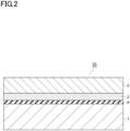
- a gas barrier laminate may be a gas barrier laminate 20 including a substrate layer 1, an anchor coat layer 4, a metal oxide layer 2, and a gas barrier cover layer 3 in this order.
- a flattening layer may be provided to reduce asperities of the substrate layer.
- Examples of the coating agent for forming the anchor coat layer or flattening layer may include acrylic resins, epoxy resins, acrylic urethane resins, polyester polyurethane resins, and polyether polyurethane resins. Of these coating agents, acrylic urethane resins and polyester polyurethane resins are preferred from the perspective of heat resistance and interlayer adhesion strength.
- the metal oxide layer contains a metal oxide and may have a structure formed of a single layer or a structure formed of two or more layers.
- the material forming the metal oxide layer may include metal oxides such as a silicon oxide, aluminum oxide, magnesium oxide, and tin oxide. From the perspective of barrier properties, the metal oxide may need to be selected from the group consisting of silicon oxide and aluminum oxide. Furthermore, the metal oxide layer may contain nitrogen or aluminum atoms. Using a metal oxide, high barrier properties can be achieved with a considerably thin layer that does not affect recyclability of the gas barrier laminate.
- the thickness of the metal oxide layer is preferred to be 3 nm or more and 100 nm or less. If the thickness is 3 nm or more, sufficient gas barrier properties can be achieved. Also, if the thickness is 100 nm or less, the occurrence of cracking can be prevented which would otherwise occur due to increase of cure shrinkage, and can suppress deterioration in gas barrier properties. It should be noted that, if the thickness exceeds 100 nm, the cost may tend to increase due to increase of the amount of the material used, increase of the time required for film formation, and the like, which is not preferable from an economic perspective. From a similar perspective, the thickness of the metal oxide layer is more preferred to be 10 nm or more and 50 nm or less.
- the metal oxide layer can be formed by vacuum deposition, for example.
- vacuum deposition a physical vapor deposition method or a chemical vapor deposition method can be used.
- the physical vapor deposition method may include, but are not limited to, a vacuum vapor deposition method, sputtering method, ion plating method, and the like.
- the chemical vapor deposition method may include, but are not limited to, a thermal CVD method, plasma CVD method, optical CVD method, and the like.
- a resistance heating vacuum vapor deposition method a resistance heating vacuum vapor deposition method, electron beam heating vacuum deposition method, inductive heating vacuum vapor deposition method, plasma-enhanced chemical vapor deposition method (PECVD method), or the like is preferably used.
- PECVD method plasma-enhanced chemical vapor deposition method
- the gas barrier cover layer has the effect of protecting the metal oxide layer, and preventing the occurrence of cracking in the metal oxide when deformed. Furthermore, the gas barrier cover layer has gas barrier properties. Provision of the gas barrier cover layer can develop high gas barrier properties in the gas barrier laminate due to the synergistic effect with the metal oxide layer.
- the gas barrier cover layer is formed through a step of forming a coating film containing the following components on the surface of the metal oxide layer.
- the silicon alkoxide or its hydrolysate (A) and the water-soluble polymer (B) become an organic-inorganic composite by hydrolyzation and dehydration condensation (e.g., sol-gel method). Specifically, the silicon alkoxide (A) forms Si-O bonds due to hydrolyzation and polycondensation reaction, while the silanol group of the hydrolysate of the silicon alkoxide forms a hydrogen bond with the hydroxy group of the water-soluble polymer (B). These reactions are assumed to develop good resistances to hot water and tension in the gas barrier cover layer.
- the silicon alkoxide (A) may be a compound expressed by the general formula: Si(OR)n (R: alkyl group such as CH 3 or C 2 H 5 ), and may be, for example, tetramethoxysilane [Si(OCH 3 ) 4 ], tetraethoxysilane [Si(OC 2 H 5 ) 4 ], or the like. Furthermore, the hydrolysate of the silicon alkoxide is obtained as a result of hydrolyzation of the above silicon alkoxide, and has a silanol group. Of the above materials, tetraethoxysilane is preferred as a silicon alkoxide because, after hydrolyzation, it is comparatively stable in aqueous solvent.
- Examples of the water-soluble polymer (B) may include polyvinyl alcohols or modifications thereof, polyvinyl pyrrolidones, starches, methyl celluloses, carboxymethyl celluloses, sodium alginates, and the like. Of these materials, polyvinyl alcohols (which may be abbreviated as PVAs hereinafter) or modifications thereof are preferred because they can enhance gas barrier properties of the gas barrier cover layer.
- PVAs referred to herein are generally obtained by saponification of polyvinyl acetates. Examples of PVAs that can be used may include so-called partially saponified PVAs in which several tens percent of the acetic acid group remains, and complete PVAs in which only a few percent of the acetic acid group remains. Furthermore, PVAs in which an ethylene group is introduced to maintain water solubility may be used as modifications of PVAs.
- the gas barrier cover layer may be formed from a coating agent that contains Component (A) and Component (B) as materials.
- a coating agent that contains Component (A) and Component (B) as materials.
- a solvent may be used. Examples of the solvent may include water, alcohol, water/alcohol mixtures, and the like.
- the gas barrier cover layer can be formed by preparing a solution that is a mixture of Component (A) or hydrolyzed Component (A) with Component (B), applying the solution to the metal oxide layer, and heating and drying the coating.
- the content ratio a/b between a content of the silicon atoms in Component (A) (mass part a) and a content of Component (B) (mass part b) may be 3/97 or more and 45/55 or less in mass ratio. If the content ratio a/b is in the above range, a gas barrier laminate exhibiting good gas barrier properties after retort sterilization treatment or physical durability tests can be obtained even when a substrate containing a polyolefin is used for the gas barrier laminate.
- the ratio a/b is 3/97 or more, water resistance of the layer can be retained, and thus dissolution and delamination of the gas barrier layer can be minimized if a liquid is filled in as contents or if hot water sterilization treatment, such as boiling or retort sterilization treatment, is performed. Also, if the ratio a/b is 45/55 or less, the layer is prevented from becoming excessively hard, and thus flexibility can be secured. From such a perspective, the ratio a/b is more preferred to be 5/95 or more and 23/77 or less.
- the content of the silicon atoms in Component (A) is a value obtained by dividing the weight of Component (A) by the molar mass of Component (A), and multiplying this by the mass (atomic weight of 28.1) of the silicon atoms (Si).
- the gas barrier cover layer may contain other components than Components (A) and (B) described above as necessary to further improve gas barrier properties.
- Other components are preferred to be aqueous materials. Examples of other components may include water dispersions of polyacrylic acids, polyurethanes, acrylic resins, and polyester resins; and metal oxides using a metal precursor obtained through a sol-gel method. If these components are to be contained, they may be formulated into the above coating agent.
- a leveling agent such as a leveling agent, antifoamer, UV absorber, antioxidant, silane coupling agent, or metal chelator, may be formulated, as necessary, into the coating agent, for example.
- a known method can be used as a method of applying the coating agent in the gas barrier cover layer.
- a wet film formation method such as gravure coating, dip coating, reverse coating, wire bar coating, or die coating, can be used.
- the thickness of the gas barrier cover layer is preferred to be, for example, 0.1 ⁇ m or more and 1 ⁇ m or less. If the thickness is 0.1 ⁇ m or more, the layer is prevented from becoming excessively thin and thus can obtain sufficient gas barrier properties. If the thickness is 1 ⁇ m or less, the film is less likely to curl and will have good processing suitability.
- the gas barrier laminate has good gas barrier properties which can be exhibited even after retort sterilization treatment or physical durability tests.
- oxygen permeability that can be achieved by the gas barrier laminate at a temperature of 30°C and a relative humidity of 70% may preferably be, for example, 10 cc/m 2 ⁇ day ⁇ atm or less, more preferably 5 cc/m 2 ⁇ day ⁇ atm or less, and even more preferably 3 cc/m 2 ⁇ day ⁇ atm or less.
- oxygen permeability that can be achieved by the gas barrier laminate at a temperature of 121°C after 30-minute retort sterilization treatment may preferably be, for example, 10 cc/m 2 ⁇ day ⁇ atm or less, more preferably 5 cc/m 2 ⁇ day ⁇ atm or less, and even more preferably 1 cc/m 2 ⁇ day ⁇ atm or less.
- oxygen permeability that can be achieved after performing Gelbo flex tests (physical durability tests) 5 times may preferably be 10 cc/m 2 ⁇ day ⁇ atm or less, more preferably 5 cc/m 2 ⁇ day ⁇ atm or less, and even more preferably 3 cc/m 2 ⁇ day ⁇ atm or less.
- oxygen permeability that can be achieved after performing retort sterilization treatment at a temperature of 121°C for 30 minutes and after performing Gelbo flex tests (physical durability tests) 5 times may preferably be 11 cc/m 2 ⁇ day ⁇ atm or less and more preferably 10 cc/m 2 ⁇ day ⁇ atm or less.
- a packaging bag according to the present embodiment includes the gas barrier laminate described above.
- a method of producing a packaging bag includes, specifically, the steps of laminating a sealant layer on a gas barrier cover layer via an adhesive layer to produce a packaging material, and shaping the packaging material into a bag-like form.
- the gas barrier laminate has good hot water resistance. Accordingly, by selecting an adhesive layer and a sealant layer having hot water resistance, the packaging material obtained can also have good hot water resistance. Packaging materials having good hot water resistance can be applied to packaging bodies which are subjected to heat sterilization treatment. It should be noted that a stretched or unstretched polypropylene film, for example, may be used as a sealant layer.
- the thickness of the sealant layer is not particularly limited but may be, for example, 30 ⁇ m or more and 100 ⁇ m or less.
- the adhesive layer adheres between the gas barrier laminate and the sealant layer.
- the adhesive forming the adhesive layer may include polyurethane resins each obtained by the action of a bifunctional or higher isocyanate compound on a main resin such as a polyester polyol, polyether polyol, acrylic polyol, or carbonate polyol.
- the polyols may be used singly or in combination of two or more.
- the adhesive layer may be formed by formulating a carbodiimide compound, oxazoline compound, epoxy compound, phosphorus compound, silane coupling agent, or the like into the polyurethane resins mentioned above. From the perspective of environmental friendliness, the adhesive layer may use biomass-derived polymer components or biodegradable polymer components.
- the coating amount of the adhesive layer may be, for example, 1 g/m 2 to 10 g/m 2 from the perspective of achieving desired adhesion strength, followability, processability, and the like.
- the packaging bag may be one which is shaped into a bag-like form by folding a single sheet of a packaging material in half so that surfaces of the sealant layer face each other, followed by heat sealing the three sides, or may be one which is shaped into a bag-like form by overlapping two sheets of a packaging material with each other so that the sealant layers face each other, followed by heat sealing the four sides.
- the packaging bag can accommodate contents, such as foods and pharmaceuticals.
- the packaging bag may have a shape with bent portions as in standing pouches, and the like. The packaging bag according to the present embodiment can maintain high gas barrier properties even in a shape with bent portions.
- Another mode of the packaging bag may be a spouted packaging bag.
- Structures of the spouted packaging bag may include a structure in which a spout is sandwiched and fixed between two gas barrier laminates forming the packaging bag, or a structure in which a spout plug is adhered and fixed in a hole formed in one surface of the packaging bag.
- the spout plug can be provided to the top of the packaging bag, or may be provided to a top corner of the packaging bag, or may be provided to the side or the bottom of the packaging bag.
- a straw reaching the container bottom may be provided in addition to the spout plug (so-called spout) so that one can suck the contents through the straw by directly putting one's mouth on the spout.
- spout plug so that one can suck the contents through the straw by directly putting one's mouth on the spout.
- FIG. 3 is a perspective view illustrating an embodiment of a spouted packaging bag (Gazette bag with spout).
- a spouted packaging bag 100 shown in Fig. 3 has a structure in which a spout 104 is sandwiched between seal portions 130 of a gas barrier laminate forming a packaging bag 140.
- the spout 104 is provided with a straw 105 which reaches the bottom of the container.
- the spouted packaging bag 100 can be sealed by closing a spout cap 104a.
- the packaging bag 140 forming the spouted packaging bag 100 may be a Gazette bag whose lower part can be spread and bulged when it is filled with contents to stand upright by itself.
- the gas barrier laminate of the present embodiment includes a substrate layer containing a polyolefin and a resin layer containing a polyolefin, and therefore, it is soft and retains high gas barrier properties even after being deformed, and thus can be preferably used as a squeeze pouch.
- the squeeze pouch may be provided with a spout that can be re-sealed, or may have a structure in which the pouch, as a disposable pouch, can be cut to attach a spout thereto.
- Another mode of the spouted packaging bag may be a bag-in box that is a carton (outer box) in which a bag (inner bag) containing a liquid such as a soft drink or an alcoholic drink is accommodated.
- the gas barrier laminate of the present embodiment can be used for the bag accommodated in the bag-in box, and in particular, for a bag body provided with a spout (tube) for discharging the liquid.
- all of the spouted packaging bags described above uses a resin, which is the same as the resin used in the substrate layer and the resin layer of the gas barrier laminate, for the spout portion or the entire spout including the cap, from the perspective of improving recyclability.
- the gas barrier laminate of the present embodiment can be used for the body of a tube container.
- Tube containers generally include a body formed of a gas barrier laminate and a discharge portion produced through extrusion.
- the discharge portion includes a spout portion through which the contents are discharged, and a shoulder portion that guides the contents retained in the body to the spout portion.
- FIG. 4 is a front elevational view illustrating an embodiment of a tube container.
- a tube container 500 shown in Fig. 4 includes a body 510 formed of a gas barrier laminate, a discharge portion 520 attached to an end of the body 510, and a cap 530 attached to the discharge portion 520.
- the body 510 is a cylindrical member formed by bonding surfaces of the sealant layer of the gas barrier laminate together at a seal portion 513 and closing a bottom portion 511 at an end which is opposite to the end provided with the discharge portion 520 to accommodate contents therein.
- the discharge portion 520 includes a spout portion 522 through which the contents are discharged, and a shoulder portion 521 which guides the contents retained in the body 510 to the spout portion 522.
- the cap 530 is a member which can close and open the opening of the spout portion 522.
- a laminate tube which is a type of a tube container, may have a body of a layer structure including, for example, a first resin layer (sealant layer) as an innermost layer, adhesive layer, gas barrier cover layer, metal oxide layer, anchor coat layer, substrate layer, adhesive layer, and second resin layer (sealant layer) in this order, or including a second resin layer (sealant layer) as an innermost layer, adhesive layer, substrate layer, anchor coat layer, metal oxide layer, gas barrier cover layer, adhesive layer, and first resin layer (sealant layer) in this order.
- a print layer may be provided on the surface of the second resin layer and bonded to the substrate via the adhesive layer, or may be provided on the surface of the first resin layer and bonded to the gas barrier cover layer-formed surface of the substrate via the adhesive layer.
- the first or second resin layer as the outermost layer does not have to serve as a sealant layer, but may serve as a resin layer similar to the substrate layer not aiming heat sealing, while surfaces of the sealant layer as an innermost layer may be placed face-to-face and bonded together at the ends (seal portion) of the gas barrier laminate to form the body into a cylindrical shape.
- the outermost layer is not required to serve as a sealant layer, a high density polyethylene or polypropylene resin can be selected as a material of the outermost layer, and thus durability and decorativeness of the tube container can be enhanced.
- sealant layers generally require a thickness of 60 ⁇ m to 100 ⁇ m
- use of a substrate (with a thickness of about 20 ⁇ m to 30 ⁇ m), which is not a sealant layer, as an outermost layer, as an outermost layer can significantly reduce the amount of plastic used for the entire container.
- the substrate layer can be used as an outermost layer without providing the second resin layer. Accordingly, the amount of plastic used for the entire tube container can be further reduced.
- a print layer may be formed on the substrate, which is an outermost layer, and protected by an overprint varnish.
- the tube container which is not provided with a sealant layer as an outermost layer will have a body in which the laminate is thinner than that of the tube container provided with sealant layers on both surfaces. Therefore, the stress applied to the gas barrier layer of the former tube container when deformed is considered to be relatively larger; however, the laminate of the present invention can be preferably used due to having gas barrier properties and retaining them at a high level even after being deformed.
- the tube container can have a shape in which the shoulder portion is vertically provided with respect to the body without being tapered.
- the substrate layer and the sealant layer of the gas barrier laminate are made of the same resin, recyclability can be improved.
- the materials of the discharge portion and the cap of the tube container There is no particular limitation in the materials of the discharge portion and the cap of the tube container; however, if the same resin as that of the substrate layer is used, recyclability can be further improved.
- an easy-to-separate film for closing the opening may be bonded to the spout portion from outside.
- the gas barrier laminate of the present embodiment may be combined with an easy-to-separate sealant for use as such a lid for sealing the opening.
- a solution was prepared by mixing tetraethoxysilane (product name: KBEO4, solid content: 100%, manufactured by Shin-Etsu Chemical Co., Ltd., which may be termed TEOS hereinafter), methanol (Kanto Kagaku), and 0.1N hydrochloric acid (Kanto Kagaku) at a weight ratio of 45/15/40, and hydrolyzing the mixture.
- This solution was mixed with a 5% aqueous solution of a polyvinyl alcohol (product name: Kuraray POVAL 60-98 manufactured by Kuraray Co., Ltd., which may be termed PVA hereinafter) to obtain a coating liquid (1).
- the solutions were mixed so that a content ratio a/b between the content of the silicon atoms (mass part a) and the content of PVA (mass part b) in the coating liquid (1) would be 40/60 in mass ratio.
- the content of the silicon atoms was calculated by dividing the weight of TEOS by the molar mass of TEOS, and multiplying this by the mass (atomic weight of 28.1) of the silicon atoms (Si). Specifically, the content of the silicon atoms in 100 g of TEOS was 13.5 g.
- a coating liquid (2) was obtained as in the process of obtaining the coating liquid (1) except that the solutions were mixed so that the content ratio a/b would be 3/97.
- a coating liquid (3) was obtained as in the process of obtaining the coating liquid (1) except that the solutions were mixed so that the content ratio a/b would be 20/80.
- a coating liquid (4) was obtained as in the process of obtaining the coating liquid (1) except that the solutions were mixed so that the content ratio a/b would be 15/85.
- a coating liquid (5) was obtained as in the process of obtaining the coating liquid (1) except that the solutions were mixed so that the content ratio a/b would be 5/95.
- a coating liquid (6) was obtained as in the process of obtaining the coating liquid (1) except that the solutions were mixed so that the content ratio a/b would be 45/55.
- a coating liquid (7) was obtained as in the process of obtaining the coating liquid (1) except that the solutions were mixed so that the content ratio a/b would be 1/99.
- a coating liquid (8) was obtained as in the process of obtaining the coating liquid (1) except that the solutions were mixed so that the content ratio a/b would be 70/30.
- a coating liquid (9) was obtained as in the process of obtaining the coating liquid (1) except that the solutions were mixed so that the content ratio a/b would be 50/50.
- a silicon oxide was vapor deposited on the corona treated surface of the film using an electron beam vacuum vapor deposition method to form a vapor deposited silicon oxide film with a thickness of 25 nm as a metal oxide layer. Furthermore, the coating liquid (1) was applied using a bar coating method so that the cured thickness would be 1.5 ⁇ m, followed by drying at 60°C for 1 minute in an oven, to obtain a gas barrier laminate.
- OPP film product name: Pyrene P2161 manufactured by Toyobo Co., Ltd., film thickness: 20 ⁇ m
- a polyester resin was applied in an amount of 0.1 g/m 2 as an anchor coat layer on the corona treated surface of the film.
- silicon oxide was vapor deposited on the anchor coat layer using an electron beam vacuum vapor deposition method to form a vapor deposited silicon oxide film with a thickness of 25 nm as a metal oxide layer.
- the coating liquid (2) was applied using a bar coating method so that the cured thickness would be 0.8 ⁇ m, followed by drying at 60°C for 1 minute in an oven to obtain a gas barrier laminate.
- a gas barrier laminate was obtained as in the process of Example 1 except that the coating liquid (3) was used instead of the coating liquid (1).
- a gas barrier laminate was obtained as in the process of Example 2 except that the coating liquid (4) was applied instead of the coating liquid (2) so that the cured thickness would be 2.0 ⁇ m.
- a gas barrier laminate was obtained as in the process of Example 2 except that the coating liquid (4) was used instead of the coating liquid (2).
- a gas barrier laminate was obtained as in the process of Example 2 except that the coating liquid (5) was used instead of the coating liquid (2).
- a gas barrier laminate was obtained as in the process of Example 2 except that the coating liquid (6) was used instead of the coating liquid (2).
- a gas barrier laminate was obtained as in the process of Example 2 except that the coating liquid (7) was used instead of the coating liquid (2).
- a gas barrier laminate was obtained as in the process of Example 2 except that the coating liquid (8) was applied instead of the coating liquid (2) so that the cured thickness would be 1.5 ⁇ m.
- a gas barrier laminate was obtained as in the process of Example 2 except that the coating liquid (9) was used instead of the coating liquid (2).
- An unstretched polypropylene film (CPP, product name: Torayfan NO ZK207 manufactured by Toray Advanced Film Co., Ltd., film thickness: 60 ⁇ m) was laminated on the gas barrier cover layer of each of the gas barrier laminates obtained in Examples 1 to 7 and Comparative Examples 1 to 3 via a two-part type adhesive (product name: A525/A52 manufactured by Mitsui Chemicals, Inc.) using a dry lamination method so that the application quantity after drying would be 3 g/m 2 to prepare a packaging material (laminate film).
- CPP unstretched polypropylene film
- pouches with a size of 210 mm long by 150 mm wide having seal portions at four sides were prepared. Also, sample pouches used for evaluating the results of physical durability tests following retort sterilization treatment were prepared with a size of 315 mm long by 230 mm wide. Both types of pouches were filled with water as contents and subjected to retort sterilization treatment at 121°C for 30 minutes.
- the packaging materials obtained from the gas barrier laminates of Examples 1 to 7 and Comparative Examples 1 to 3 and upper surfaces of the pouches subjected to retort sterilization treatment were each cut to a size of 295 mm long by 210 mm wide for use as samples.
- Each sample was loaded on a fixed head of a Gelbo Flex tester manufactured by Tester Sangyo Co., Ltd. so as to have a cylindrical shape of 87.5 mm diameter by 210 mm length.
- the sample was subjected to flexing, with both ends thereof held at an initial gripping interval of 175 mm therebetween, by applying a 440° twist with an 87.5 mm stroke, and repeating this motion 5 times at a rate of 40 reciprocations per minute.
- Oxygen permeability was measured for the gas barrier laminates, the samples subjected to retort sterilization treatment, the samples subjected to physical durability tests, and the samples subjected to abusive tests following retort sterilization treatment obtained from Examples 1 to 7 and Comparative Examples 1 to 3, using an oxygen permeability tester (OX-TRAN2/20 manufactured by Modern Controls Inc.) under conditions of 30°C and 70% relative humidity.
- OX-TRAN2/20 manufactured by Modern Controls Inc. oxygen permeability tester
- Table 1 Anchor coat layer Gas barrier cover layer Oxygen permeability (cc/m 2 ⁇ day ⁇ atm) a/b Thickness ( ⁇ m) Untreated After retort treatment After physical durability tests After retort and physical durability tests Ex.
- the gas barrier laminates of Examples 1 to 7 could achieve good gas barrier properties after retort sterilization treatment or physical durability tests even when OPP was used as a substrate.
- a gas barrier laminate retaining good gas barrier properties after physical durability tests or retort sterilization treatment can be provided, even when a material which is poor in gas barrier properties, such as a single plastic film of a polyolefin or the like including a biaxially stretched polypropylene, for example, is used as a substrate of the gas barrier laminate.
Landscapes
- Engineering & Computer Science (AREA)
- Mechanical Engineering (AREA)
- Chemical & Material Sciences (AREA)
- Life Sciences & Earth Sciences (AREA)
- Materials Engineering (AREA)
- Wood Science & Technology (AREA)
- Organic Chemistry (AREA)
- Laminated Bodies (AREA)
- Wrappers (AREA)
Abstract
Description
- The present invention relates to gas barrier laminates and packaging bags.
- Packaging materials used for packaging foods, pharmaceuticals, or other articles are required to have gas barrier properties to prevent the effects of oxygen, water vapor, or other gases which permeate the packaging materials, from altering the contents.
- As packaging materials having gas barrier properties, gas barrier laminates including a deposited inorganic layer or a gas barrier layer containing a water-soluble polymer are generally used.
- For example, in PTL 1 shown below, gas barrier properties are developed by forming a thin deposited film layer on a plastic substrate, followed by forming a gas barrier layer thereon. In
PTL 2, gas barrier properties are developed by forming a gas barrier layer on a plastic substrate, so that even when a biaxially stretched polypropylene is used, good barrier properties can be developed. -
- PTL 1:
JP 2018-1631 A - PTL 2:
JP 3949551 B - However, if packaging bags using a substrate containing a polyolefin are subjected to retort sterilization treatment or physical durability tests, there may arise an issue of impairing gas barrier properties.
- The present invention has been made in light of the circumstances set forth above and aims to provide a gas barrier laminate exhibiting good gas barrier properties after retort sterilization treatment or physical durability tests even when a substrate containing a polyolefin is used for the gas barrier laminate, and to provide a packaging bag.
- The present invention provides a gas barrier laminate including a substrate layer containing a polyolefin, a metal oxide layer, and a gas barrier cover layer in this order. In the gas barrier laminate, the gas barrier cover layer contains a silicon alkoxide or a hydrolysate thereof and a water-soluble polymer, and a content ratio a/b between a content of silicon atoms of the silicon alkoxide or a hydrolysate thereof (mass part a) and a content of the water-soluble polymer (mass part b) is 3/97 or more and 45/55 or less in mass ratio.
- The content ratio a/b may be 5/95 or more in mass ratio.
- The gas barrier laminate may further include an anchor coat layer. In the gas barrier laminate, the metal oxide layer is formed on the substrate layer via the anchor coat layer.
- The gas barrier cover layer may have a thickness of 0.1 µm or more and 1 µm or less.
- The present invention also provides a packaging bag including the gas barrier laminate described above.
- The present invention also provides a tube container including the gas barrier laminate described above.
- According to the present invention, there can be provided a gas barrier laminate exhibiting good gas barrier properties after retort sterilization treatment or physical durability tests even when a substrate containing a polyolefin is used for the gas barrier laminate, and there can also be provided a packaging bag and a tube container.
-
-
Fig. 1 is a schematic cross-sectional view illustrating a gas barrier laminate according to an embodiment of the present invention. -
Fig. 2 is a schematic cross-sectional view illustrating a gas barrier laminate according to another embodiment of the present invention. -
Fig. 3 is a perspective view illustrating an embodiment of a spouted packaging bag. -
Fig. 4 is a front elevational view illustrating an embodiment of a tube container. - With reference to the drawings as appropriate, some embodiments of the present invention will be described below in detail. It should be noted that the present invention should not be construed as being limited to the following embodiments.
-
Fig. 1 is a schematic cross-sectional view illustrating a gas barrier laminate according to an embodiment. Agas barrier laminate 10 according to an embodiment includes a substrate layer 1, ametal oxide layer 2, and a gasbarrier cover layer 3 in this order. - The substrate layer is a film (base film) serving as a support and contains a polyolefin. The substrate layer may be a film formed of a polyolefin, and may further include a film other than the polyolefin film. Furthermore, the substrate layer may include a multilayer film. The polyolefin may be a stretched film or an unstretched film, but may preferably be a stretched polyolefin, such as, for example, a biaxially stretched polyolefin, and the like. Alternatively, a resin-derived recycled film, such as a polypropylene recycled from industrial waste, may be used.
- The thickness of the substrate layer is not particularly limited but the substrate layer may preferably have a typical thickness, for example, of about 3 µm or more and 100 µm or less. If the substrate layer includes a plurality of films, the total thickness may be in the above range.
- The substrate may contain additives, as necessary, such as an antistatic agent, UV absorber, plasticizer, and lubricant. Furthermore, the surface of the substrate may undergo modification treatments such as a corona treatment, flame treatment, plasma treatment, or adhesion enhancing treatment, or may be further provided with an anchor coat layer which has undergone these treatments. If an anchor coat layer is also included, the metal oxide layer may be formed on the substrate layer via the anchor coat layer. Specifically, as shown in
Fig. 2 , a gas barrier laminate according to an embodiment may be agas barrier laminate 20 including a substrate layer 1, an anchor coat layer 4, ametal oxide layer 2, and a gasbarrier cover layer 3 in this order. - Separately, a flattening layer may be provided to reduce asperities of the substrate layer.
- Examples of the coating agent for forming the anchor coat layer or flattening layer may include acrylic resins, epoxy resins, acrylic urethane resins, polyester polyurethane resins, and polyether polyurethane resins. Of these coating agents, acrylic urethane resins and polyester polyurethane resins are preferred from the perspective of heat resistance and interlayer adhesion strength.
- The metal oxide layer contains a metal oxide and may have a structure formed of a single layer or a structure formed of two or more layers. Examples of the material forming the metal oxide layer may include metal oxides such as a silicon oxide, aluminum oxide, magnesium oxide, and tin oxide. From the perspective of barrier properties, the metal oxide may need to be selected from the group consisting of silicon oxide and aluminum oxide. Furthermore, the metal oxide layer may contain nitrogen or aluminum atoms. Using a metal oxide, high barrier properties can be achieved with a considerably thin layer that does not affect recyclability of the gas barrier laminate.
- The thickness of the metal oxide layer is preferred to be 3 nm or more and 100 nm or less. If the thickness is 3 nm or more, sufficient gas barrier properties can be achieved. Also, if the thickness is 100 nm or less, the occurrence of cracking can be prevented which would otherwise occur due to increase of cure shrinkage, and can suppress deterioration in gas barrier properties. It should be noted that, if the thickness exceeds 100 nm, the cost may tend to increase due to increase of the amount of the material used, increase of the time required for film formation, and the like, which is not preferable from an economic perspective. From a similar perspective, the thickness of the metal oxide layer is more preferred to be 10 nm or more and 50 nm or less.
- The metal oxide layer can be formed by vacuum deposition, for example. In vacuum deposition, a physical vapor deposition method or a chemical vapor deposition method can be used. Examples of the physical vapor deposition method may include, but are not limited to, a vacuum vapor deposition method, sputtering method, ion plating method, and the like. Examples of the chemical vapor deposition method may include, but are not limited to, a thermal CVD method, plasma CVD method, optical CVD method, and the like.
- In the vacuum deposition method, a resistance heating vacuum vapor deposition method, electron beam heating vacuum deposition method, inductive heating vacuum vapor deposition method, plasma-enhanced chemical vapor deposition method (PECVD method), or the like is preferably used.
- The gas barrier cover layer has the effect of protecting the metal oxide layer, and preventing the occurrence of cracking in the metal oxide when deformed. Furthermore, the gas barrier cover layer has gas barrier properties. Provision of the gas barrier cover layer can develop high gas barrier properties in the gas barrier laminate due to the synergistic effect with the metal oxide layer.
- The gas barrier cover layer is formed through a step of forming a coating film containing the following components on the surface of the metal oxide layer.
- (A) A silicon alkoxide or its hydrolysate (which may be termed Component (A) hereinafter)
- (B) A water-soluble polymer (which may be termed Component (B) hereinafter)
- The silicon alkoxide or its hydrolysate (A) and the water-soluble polymer (B) become an organic-inorganic composite by hydrolyzation and dehydration condensation (e.g., sol-gel method). Specifically, the silicon alkoxide (A) forms Si-O bonds due to hydrolyzation and polycondensation reaction, while the silanol group of the hydrolysate of the silicon alkoxide forms a hydrogen bond with the hydroxy group of the water-soluble polymer (B). These reactions are assumed to develop good resistances to hot water and tension in the gas barrier cover layer.
- The silicon alkoxide (A) may be a compound expressed by the general formula: Si(OR)n (R: alkyl group such as CH3 or C2H5), and may be, for example, tetramethoxysilane [Si(OCH3)4], tetraethoxysilane [Si(OC2H5)4], or the like. Furthermore, the hydrolysate of the silicon alkoxide is obtained as a result of hydrolyzation of the above silicon alkoxide, and has a silanol group. Of the above materials, tetraethoxysilane is preferred as a silicon alkoxide because, after hydrolyzation, it is comparatively stable in aqueous solvent.
- Examples of the water-soluble polymer (B) may include polyvinyl alcohols or modifications thereof, polyvinyl pyrrolidones, starches, methyl celluloses, carboxymethyl celluloses, sodium alginates, and the like. Of these materials, polyvinyl alcohols (which may be abbreviated as PVAs hereinafter) or modifications thereof are preferred because they can enhance gas barrier properties of the gas barrier cover layer. PVAs referred to herein are generally obtained by saponification of polyvinyl acetates. Examples of PVAs that can be used may include so-called partially saponified PVAs in which several tens percent of the acetic acid group remains, and complete PVAs in which only a few percent of the acetic acid group remains. Furthermore, PVAs in which an ethylene group is introduced to maintain water solubility may be used as modifications of PVAs.
- The gas barrier cover layer may be formed from a coating agent that contains Component (A) and Component (B) as materials. For the coating agent, a solvent may be used. Examples of the solvent may include water, alcohol, water/alcohol mixtures, and the like.
- The gas barrier cover layer can be formed by preparing a solution that is a mixture of Component (A) or hydrolyzed Component (A) with Component (B), applying the solution to the metal oxide layer, and heating and drying the coating. In this case, the content ratio a/b between a content of the silicon atoms in Component (A) (mass part a) and a content of Component (B) (mass part b) may be 3/97 or more and 45/55 or less in mass ratio. If the content ratio a/b is in the above range, a gas barrier laminate exhibiting good gas barrier properties after retort sterilization treatment or physical durability tests can be obtained even when a substrate containing a polyolefin is used for the gas barrier laminate. In particular, if the ratio a/b is 3/97 or more, water resistance of the layer can be retained, and thus dissolution and delamination of the gas barrier layer can be minimized if a liquid is filled in as contents or if hot water sterilization treatment, such as boiling or retort sterilization treatment, is performed. Also, if the ratio a/b is 45/55 or less, the layer is prevented from becoming excessively hard, and thus flexibility can be secured. From such a perspective, the ratio a/b is more preferred to be 5/95 or more and 23/77 or less.
- It should be noted that the content of the silicon atoms in Component (A) (mass part a) is a value obtained by dividing the weight of Component (A) by the molar mass of Component (A), and multiplying this by the mass (atomic weight of 28.1) of the silicon atoms (Si).
- The gas barrier cover layer may contain other components than Components (A) and (B) described above as necessary to further improve gas barrier properties. Other components are preferred to be aqueous materials. Examples of other components may include water dispersions of polyacrylic acids, polyurethanes, acrylic resins, and polyester resins; and metal oxides using a metal precursor obtained through a sol-gel method. If these components are to be contained, they may be formulated into the above coating agent.
- Also, other materials, such as a leveling agent, antifoamer, UV absorber, antioxidant, silane coupling agent, or metal chelator, may be formulated, as necessary, into the coating agent, for example.
- A known method can be used as a method of applying the coating agent in the gas barrier cover layer. Specifically, a wet film formation method, such as gravure coating, dip coating, reverse coating, wire bar coating, or die coating, can be used.
- The thickness of the gas barrier cover layer is preferred to be, for example, 0.1 µm or more and 1 µm or less. If the thickness is 0.1 µm or more, the layer is prevented from becoming excessively thin and thus can obtain sufficient gas barrier properties. If the thickness is 1 µm or less, the film is less likely to curl and will have good processing suitability.
- The gas barrier laminate has good gas barrier properties which can be exhibited even after retort sterilization treatment or physical durability tests. Specifically, oxygen permeability that can be achieved by the gas barrier laminate at a temperature of 30°C and a relative humidity of 70% may preferably be, for example, 10 cc/m2·day·atm or less, more preferably 5 cc/m2·day·atm or less, and even more preferably 3 cc/m2·day·atm or less. Also, oxygen permeability that can be achieved by the gas barrier laminate at a temperature of 121°C after 30-minute retort sterilization treatment may preferably be, for example, 10 cc/m2·day·atm or less, more preferably 5 cc/m2·day·atm or less, and even more preferably 1 cc/m2·day·atm or less. Furthermore, oxygen permeability that can be achieved after performing Gelbo flex tests (physical durability tests) 5 times may preferably be 10 cc/m2·day·atm or less, more preferably 5 cc/m2·day·atm or less, and even more preferably 3 cc/m2·day·atm or less. In addition, oxygen permeability that can be achieved after performing retort sterilization treatment at a temperature of 121°C for 30 minutes and after performing Gelbo flex tests (physical durability tests) 5 times may preferably be 11 cc/m2·day·atm or less and more preferably 10 cc/m2·day·atm or less.
- A packaging bag according to the present embodiment includes the gas barrier laminate described above. A method of producing a packaging bag includes, specifically, the steps of laminating a sealant layer on a gas barrier cover layer via an adhesive layer to produce a packaging material, and shaping the packaging material into a bag-like form.
- The gas barrier laminate has good hot water resistance. Accordingly, by selecting an adhesive layer and a sealant layer having hot water resistance, the packaging material obtained can also have good hot water resistance. Packaging materials having good hot water resistance can be applied to packaging bodies which are subjected to heat sterilization treatment. It should be noted that a stretched or unstretched polypropylene film, for example, may be used as a sealant layer. The thickness of the sealant layer is not particularly limited but may be, for example, 30 µm or more and 100 µm or less.
- The adhesive layer adheres between the gas barrier laminate and the sealant layer. Examples of the adhesive forming the adhesive layer may include polyurethane resins each obtained by the action of a bifunctional or higher isocyanate compound on a main resin such as a polyester polyol, polyether polyol, acrylic polyol, or carbonate polyol. The polyols may be used singly or in combination of two or more. For the purpose of promoting adhesion, the adhesive layer may be formed by formulating a carbodiimide compound, oxazoline compound, epoxy compound, phosphorus compound, silane coupling agent, or the like into the polyurethane resins mentioned above. From the perspective of environmental friendliness, the adhesive layer may use biomass-derived polymer components or biodegradable polymer components. The coating amount of the adhesive layer may be, for example, 1 g/m2 to 10 g/m2 from the perspective of achieving desired adhesion strength, followability, processability, and the like.
- The packaging bag may be one which is shaped into a bag-like form by folding a single sheet of a packaging material in half so that surfaces of the sealant layer face each other, followed by heat sealing the three sides, or may be one which is shaped into a bag-like form by overlapping two sheets of a packaging material with each other so that the sealant layers face each other, followed by heat sealing the four sides. The packaging bag can accommodate contents, such as foods and pharmaceuticals. Furthermore, the packaging bag may have a shape with bent portions as in standing pouches, and the like. The packaging bag according to the present embodiment can maintain high gas barrier properties even in a shape with bent portions.
- Another mode of the packaging bag may be a spouted packaging bag. Structures of the spouted packaging bag may include a structure in which a spout is sandwiched and fixed between two gas barrier laminates forming the packaging bag, or a structure in which a spout plug is adhered and fixed in a hole formed in one surface of the packaging bag. The spout plug can be provided to the top of the packaging bag, or may be provided to a top corner of the packaging bag, or may be provided to the side or the bottom of the packaging bag. If the contents are food in the form of a liquid or a gel, a straw reaching the container bottom may be provided in addition to the spout plug (so-called spout) so that one can suck the contents through the straw by directly putting one's mouth on the spout.
-
Fig. 3 is a perspective view illustrating an embodiment of a spouted packaging bag (Gazette bag with spout). Aspouted packaging bag 100 shown inFig. 3 has a structure in which aspout 104 is sandwiched betweenseal portions 130 of a gas barrier laminate forming apackaging bag 140. Thespout 104 is provided with astraw 105 which reaches the bottom of the container. Thespouted packaging bag 100 can be sealed by closing aspout cap 104a. Thepackaging bag 140 forming thespouted packaging bag 100 may be a Gazette bag whose lower part can be spread and bulged when it is filled with contents to stand upright by itself. - Furthermore, the gas barrier laminate of the present embodiment includes a substrate layer containing a polyolefin and a resin layer containing a polyolefin, and therefore, it is soft and retains high gas barrier properties even after being deformed, and thus can be preferably used as a squeeze pouch. The squeeze pouch may be provided with a spout that can be re-sealed, or may have a structure in which the pouch, as a disposable pouch, can be cut to attach a spout thereto.
- Another mode of the spouted packaging bag may be a bag-in box that is a carton (outer box) in which a bag (inner bag) containing a liquid such as a soft drink or an alcoholic drink is accommodated. The gas barrier laminate of the present embodiment can be used for the bag accommodated in the bag-in box, and in particular, for a bag body provided with a spout (tube) for discharging the liquid.
- It is preferred that all of the spouted packaging bags described above uses a resin, which is the same as the resin used in the substrate layer and the resin layer of the gas barrier laminate, for the spout portion or the entire spout including the cap, from the perspective of improving recyclability.
- The gas barrier laminate of the present embodiment can be used for the body of a tube container. Tube containers generally include a body formed of a gas barrier laminate and a discharge portion produced through extrusion. The discharge portion includes a spout portion through which the contents are discharged, and a shoulder portion that guides the contents retained in the body to the spout portion.
-
Fig. 4 is a front elevational view illustrating an embodiment of a tube container. Atube container 500 shown inFig. 4 includes abody 510 formed of a gas barrier laminate, adischarge portion 520 attached to an end of thebody 510, and acap 530 attached to thedischarge portion 520. Thebody 510 is a cylindrical member formed by bonding surfaces of the sealant layer of the gas barrier laminate together at aseal portion 513 and closing abottom portion 511 at an end which is opposite to the end provided with thedischarge portion 520 to accommodate contents therein. Thedischarge portion 520 includes aspout portion 522 through which the contents are discharged, and ashoulder portion 521 which guides the contents retained in thebody 510 to thespout portion 522. Thecap 530 is a member which can close and open the opening of thespout portion 522. - The gas barrier laminate of the present embodiment, which has gas barrier properties and can retain them at a high level even after being deformed, is suitable for use as a body of the tube container mentioned above which is repeatedly deformed when the contents are squeezed out. A laminate tube, which is a type of a tube container, may have a body of a layer structure including, for example, a first resin layer (sealant layer) as an innermost layer, adhesive layer, gas barrier cover layer, metal oxide layer, anchor coat layer, substrate layer, adhesive layer, and second resin layer (sealant layer) in this order, or including a second resin layer (sealant layer) as an innermost layer, adhesive layer, substrate layer, anchor coat layer, metal oxide layer, gas barrier cover layer, adhesive layer, and first resin layer (sealant layer) in this order. A print layer may be provided on the surface of the second resin layer and bonded to the substrate via the adhesive layer, or may be provided on the surface of the first resin layer and bonded to the gas barrier cover layer-formed surface of the substrate via the adhesive layer. Alternatively, as a body of the tube container, the first or second resin layer as the outermost layer does not have to serve as a sealant layer, but may serve as a resin layer similar to the substrate layer not aiming heat sealing, while surfaces of the sealant layer as an innermost layer may be placed face-to-face and bonded together at the ends (seal portion) of the gas barrier laminate to form the body into a cylindrical shape. In this case, since the outermost layer is not required to serve as a sealant layer, a high density polyethylene or polypropylene resin can be selected as a material of the outermost layer, and thus durability and decorativeness of the tube container can be enhanced. Furthermore, since sealant layers generally require a thickness of 60 µm to 100 µm, use of a substrate (with a thickness of about 20 µm to 30 µm), which is not a sealant layer, as an outermost layer can significantly reduce the amount of plastic used for the entire container. In the structure in which the first resin layer is used as an innermost sealant layer, the substrate layer can be used as an outermost layer without providing the second resin layer. Accordingly, the amount of plastic used for the entire tube container can be further reduced. In this case, a print layer may be formed on the substrate, which is an outermost layer, and protected by an overprint varnish. The tube container which is not provided with a sealant layer as an outermost layer will have a body in which the laminate is thinner than that of the tube container provided with sealant layers on both surfaces. Therefore, the stress applied to the gas barrier layer of the former tube container when deformed is considered to be relatively larger; however, the laminate of the present invention can be preferably used due to having gas barrier properties and retaining them at a high level even after being deformed. In order that the contents can be completely squeezed out, the tube container can have a shape in which the shoulder portion is vertically provided with respect to the body without being tapered. If the substrate layer and the sealant layer of the gas barrier laminate are made of the same resin, recyclability can be improved. There is no particular limitation in the materials of the discharge portion and the cap of the tube container; however, if the same resin as that of the substrate layer is used, recyclability can be further improved. In order to seal the tube container until the initial opening, an easy-to-separate film for closing the opening may be bonded to the spout portion from outside. The gas barrier laminate of the present embodiment may be combined with an easy-to-separate sealant for use as such a lid for sealing the opening.
- The present invention will be described below in more detail by way of examples, but the present invention should not be construed as being limited to these examples.
- A solution was prepared by mixing tetraethoxysilane (product name: KBEO4, solid content: 100%, manufactured by Shin-Etsu Chemical Co., Ltd., which may be termed TEOS hereinafter), methanol (Kanto Kagaku), and 0.1N hydrochloric acid (Kanto Kagaku) at a weight ratio of 45/15/40, and hydrolyzing the mixture. This solution was mixed with a 5% aqueous solution of a polyvinyl alcohol (product name: Kuraray POVAL 60-98 manufactured by Kuraray Co., Ltd., which may be termed PVA hereinafter) to obtain a coating liquid (1). In this case, the solutions were mixed so that a content ratio a/b between the content of the silicon atoms (mass part a) and the content of PVA (mass part b) in the coating liquid (1) would be 40/60 in mass ratio.
- It should be noted that the content of the silicon atoms was calculated by dividing the weight of TEOS by the molar mass of TEOS, and multiplying this by the mass (atomic weight of 28.1) of the silicon atoms (Si). Specifically, the content of the silicon atoms in 100 g of TEOS was 13.5 g.
- A coating liquid (2) was obtained as in the process of obtaining the coating liquid (1) except that the solutions were mixed so that the content ratio a/b would be 3/97.
- A coating liquid (3) was obtained as in the process of obtaining the coating liquid (1) except that the solutions were mixed so that the content ratio a/b would be 20/80.
- A coating liquid (4) was obtained as in the process of obtaining the coating liquid (1) except that the solutions were mixed so that the content ratio a/b would be 15/85.
- A coating liquid (5) was obtained as in the process of obtaining the coating liquid (1) except that the solutions were mixed so that the content ratio a/b would be 5/95.
- A coating liquid (6) was obtained as in the process of obtaining the coating liquid (1) except that the solutions were mixed so that the content ratio a/b would be 45/55.
- A coating liquid (7) was obtained as in the process of obtaining the coating liquid (1) except that the solutions were mixed so that the content ratio a/b would be 1/99.
- A coating liquid (8) was obtained as in the process of obtaining the coating liquid (1) except that the solutions were mixed so that the content ratio a/b would be 70/30.
- A coating liquid (9) was obtained as in the process of obtaining the coating liquid (1) except that the solutions were mixed so that the content ratio a/b would be 50/50.
- Using a biaxially stretched polypropylene film (OPP film, product name: Pyrene P2161 manufactured by Toyobo Co., Ltd., film thickness: 20 µm) as a substrate, a silicon oxide was vapor deposited on the corona treated surface of the film using an electron beam vacuum vapor deposition method to form a vapor deposited silicon oxide film with a thickness of 25 nm as a metal oxide layer. Furthermore, the coating liquid (1) was applied using a bar coating method so that the cured thickness would be 1.5 µm, followed by drying at 60°C for 1 minute in an oven, to obtain a gas barrier laminate.
- Using a biaxially stretched polypropylene film (OPP film, product name: Pyrene P2161 manufactured by Toyobo Co., Ltd., film thickness: 20 µm) as a substrate, a polyester resin was applied in an amount of 0.1 g/m2 as an anchor coat layer on the corona treated surface of the film. Subsequently, silicon oxide was vapor deposited on the anchor coat layer using an electron beam vacuum vapor deposition method to form a vapor deposited silicon oxide film with a thickness of 25 nm as a metal oxide layer. Furthermore, the coating liquid (2) was applied using a bar coating method so that the cured thickness would be 0.8 µm, followed by drying at 60°C for 1 minute in an oven to obtain a gas barrier laminate.
- A gas barrier laminate was obtained as in the process of Example 1 except that the coating liquid (3) was used instead of the coating liquid (1).
- A gas barrier laminate was obtained as in the process of Example 2 except that the coating liquid (4) was applied instead of the coating liquid (2) so that the cured thickness would be 2.0 µm.
- A gas barrier laminate was obtained as in the process of Example 2 except that the coating liquid (4) was used instead of the coating liquid (2).
- A gas barrier laminate was obtained as in the process of Example 2 except that the coating liquid (5) was used instead of the coating liquid (2).
- A gas barrier laminate was obtained as in the process of Example 2 except that the coating liquid (6) was used instead of the coating liquid (2).
- A gas barrier laminate was obtained as in the process of Example 2 except that the coating liquid (7) was used instead of the coating liquid (2).
- A gas barrier laminate was obtained as in the process of Example 2 except that the coating liquid (8) was applied instead of the coating liquid (2) so that the cured thickness would be 1.5 µm.
- A gas barrier laminate was obtained as in the process of Example 2 except that the coating liquid (9) was used instead of the coating liquid (2).
- An unstretched polypropylene film (CPP, product name: Torayfan NO ZK207 manufactured by Toray Advanced Film Co., Ltd., film thickness: 60 µm) was laminated on the gas barrier cover layer of each of the gas barrier laminates obtained in Examples 1 to 7 and Comparative Examples 1 to 3 via a two-part type adhesive (product name: A525/A52 manufactured by Mitsui Chemicals, Inc.) using a dry lamination method so that the application quantity after drying would be 3 g/m2 to prepare a packaging material (laminate film).
- Using the packaging materials obtained from the gas barrier laminates of Examples 1 to 7 and Comparative Examples 1 to 3, pouches with a size of 210 mm long by 150 mm wide having seal portions at four sides were prepared. Also, sample pouches used for evaluating the results of physical durability tests following retort sterilization treatment were prepared with a size of 315 mm long by 230 mm wide. Both types of pouches were filled with water as contents and subjected to retort sterilization treatment at 121°C for 30 minutes.
- The packaging materials obtained from the gas barrier laminates of Examples 1 to 7 and Comparative Examples 1 to 3 and upper surfaces of the pouches subjected to retort sterilization treatment were each cut to a size of 295 mm long by 210 mm wide for use as samples. Each sample was loaded on a fixed head of a Gelbo Flex tester manufactured by Tester Sangyo Co., Ltd. so as to have a cylindrical shape of 87.5 mm diameter by 210 mm length. The sample was subjected to flexing, with both ends thereof held at an initial gripping interval of 175 mm therebetween, by applying a 440° twist with an 87.5 mm stroke, and repeating this motion 5 times at a rate of 40 reciprocations per minute.
- Oxygen permeability was measured for the gas barrier laminates, the samples subjected to retort sterilization treatment, the samples subjected to physical durability tests, and the samples subjected to abusive tests following retort sterilization treatment obtained from Examples 1 to 7 and Comparative Examples 1 to 3, using an oxygen permeability tester (OX-TRAN2/20 manufactured by Modern Controls Inc.) under conditions of 30°C and 70% relative humidity. The measurement results are shown in Table 1.
[Table 1] Anchor coat layer Gas barrier cover layer Oxygen permeability (cc/m2·day·atm) a/b Thickness (µm) Untreated After retort treatment After physical durability tests After retort and physical durability tests Ex. 1 Absent 40/60 1.5 1.2 2.8 5.1 6.8 Ex.2 Present 3/97 0.8 0.1 2.6 0.5 4.5 Ex.3 Absent 20/80 1.5 1.0 2.0 1.3 6.1 Ex.4 Present 15/85 2.0 0.2 0.5 0.2 3.4 Ex.5 Present 15/85 0.8 0.2 0.3 0.3 2.9 Ex.6 Present 5/95 0.8 0.1 0.1 0.3 2.5 Ex.7 Present 45/55 0.8 0.3 0.5 7.9 9.3 CEx. 1 Present 1/99 0.8 0.4 *1 6.9 *1 CEx. 2 Present 70/30 1.5 0.1 0.3 13.9 15.7 CEx. 3 Present 50/50 0.8 0.3 0.6 10.3 11.1 ∗1: Delaminated; Ex.: Example; CEx.: Comparative Example - As shown in Table 1, the gas barrier laminates of Examples 1 to 7 could achieve good gas barrier properties after retort sterilization treatment or physical durability tests even when OPP was used as a substrate.
- In contrast, the gas barrier laminate of Comparative Example 1 with a low ratio a/b suffered delamination after retort treatment, and therefore, oxygen permeability could not be measured. Also, in Comparative Examples 2 and 3 with a high ratio a/b, oxygen permeability became high after physical durability tests, and therefore, sufficient gas barrier properties could not be achieved.
- According to the present embodiment, a gas barrier laminate retaining good gas barrier properties after physical durability tests or retort sterilization treatment can be provided, even when a material which is poor in gas barrier properties, such as a single plastic film of a polyolefin or the like including a biaxially stretched polypropylene, for example, is used as a substrate of the gas barrier laminate.
-
- 1
- Substrate layer
- 2
- Metal oxide layer
- 3
- Gas barrier cover layer
- 4
- Anchor coat layer
- 10, 20
- Gas barrier laminate
- 100
- Spouted packaging bag
- 104
- Spout
- 105
- Straw
- 140
- Packaging bag
- 500
- Tube container
- 510
- Body
- 520
- Discharge portion
- 530
- Cap
Claims (6)
- A gas barrier laminate comprising a substrate layer containing a polyolefin, a metal oxide layer, and a gas barrier cover layer in this order, wherein
the gas barrier cover layer contains a silicon alkoxide or a hydrolysate thereof and a water-soluble polymer, and a content ratio a/b between a content of silicon atoms of the silicon alkoxide or a hydrolysate thereof (mass part a) and a content of the water-soluble polymer (mass part b) is 3/97 or more and 45/55 or less in mass ratio. - The gas barrier laminate according to claim 1, wherein the content ratio a/b is 5/95 or more in mass ratio.
- The gas barrier laminate according to claim 1 or 2, further comprising an anchor coat layer, wherein the metal oxide layer is formed on the substrate layer via the anchor coat layer.
- The gas barrier laminate according to any one of claims 1 to 3, wherein the gas barrier cover layer has a thickness of 0.1 µm or more and 1 µm or less.
- A packaging bag comprising the gas barrier laminate according to any one of claims 1 to 4.
- A tube container comprising the gas barrier laminate according to any one of claims 1 to 4.
Applications Claiming Priority (2)
| Application Number | Priority Date | Filing Date | Title |
|---|---|---|---|
| JP2020078164 | 2020-04-27 | ||
| PCT/JP2021/016517 WO2021220977A1 (en) | 2020-04-27 | 2021-04-23 | Gas barrier laminate and packaging bag |
Publications (2)
| Publication Number | Publication Date |
|---|---|
| EP4144521A1 true EP4144521A1 (en) | 2023-03-08 |
| EP4144521A4 EP4144521A4 (en) | 2023-10-25 |
Family
ID=78373585
Family Applications (1)
| Application Number | Title | Priority Date | Filing Date |
|---|---|---|---|
| EP21796057.4A Pending EP4144521A4 (en) | 2020-04-27 | 2021-04-23 | GAS BARRIER LAMINATE AND PACKING BAG |
Country Status (5)
| Country | Link |
|---|---|
| US (1) | US12030286B2 (en) |
| EP (1) | EP4144521A4 (en) |
| JP (1) | JPWO2021220977A1 (en) |
| CN (1) | CN115443215A (en) |
| WO (1) | WO2021220977A1 (en) |
Families Citing this family (2)
| Publication number | Priority date | Publication date | Assignee | Title |
|---|---|---|---|---|
| JPWO2024101161A1 (en) * | 2022-11-08 | 2024-05-16 | ||
| WO2024150763A1 (en) * | 2023-01-11 | 2024-07-18 | Toppanホールディングス株式会社 | Gas barrier laminate, packaging container, and packaged product |
Family Cites Families (10)
| Publication number | Priority date | Publication date | Assignee | Title |
|---|---|---|---|---|
| JP3949551B2 (en) | 2001-09-18 | 2007-07-25 | 株式会社トクヤマ | Gas barrier film |
| JP2006062115A (en) * | 2004-08-25 | 2006-03-09 | Toppan Printing Co Ltd | Transparent barrier film for retort |
| CN107405896A (en) * | 2015-03-27 | 2017-11-28 | 凸版印刷株式会社 | Stacked film and packaging bag |
| JP6906278B2 (en) | 2016-07-04 | 2021-07-21 | 三井化学東セロ株式会社 | Barrier laminated film and food packaging |
| JP7009765B2 (en) * | 2017-03-31 | 2022-01-26 | 大日本印刷株式会社 | Easy-to-open gas barrier laminate, easy-to-open gas barrier packaging material and pillow packaging bag made of the laminate |
| WO2018181900A1 (en) * | 2017-03-31 | 2018-10-04 | 大日本印刷株式会社 | Gas barrier laminate, and gas barrier packaging material and pillow packaging bag each of which is formed of said laminate |
| JP6988153B2 (en) * | 2017-05-09 | 2022-01-05 | 凸版印刷株式会社 | Gas barrier transfer film |
| KR20200066330A (en) * | 2017-10-05 | 2020-06-09 | 도판 인사츠 가부시키가이샤 | Phosphor protective film, wavelength conversion sheet and light emitting unit |
| JP2019119132A (en) * | 2018-01-05 | 2019-07-22 | 凸版印刷株式会社 | Laminate film and molded article |
| JP7425984B2 (en) * | 2018-09-28 | 2024-02-01 | 大日本印刷株式会社 | Packaging materials for paper containers and liquid paper containers |
-
2021
- 2021-04-23 WO PCT/JP2021/016517 patent/WO2021220977A1/en not_active Ceased
- 2021-04-23 EP EP21796057.4A patent/EP4144521A4/en active Pending
- 2021-04-23 CN CN202180027265.9A patent/CN115443215A/en active Pending
- 2021-04-23 JP JP2022518027A patent/JPWO2021220977A1/ja active Pending
-
2022
- 2022-10-17 US US17/967,031 patent/US12030286B2/en active Active
Also Published As
| Publication number | Publication date |
|---|---|
| WO2021220977A1 (en) | 2021-11-04 |
| JPWO2021220977A1 (en) | 2021-11-04 |
| EP4144521A4 (en) | 2023-10-25 |
| US12030286B2 (en) | 2024-07-09 |
| US20230047527A1 (en) | 2023-02-16 |
| CN115443215A (en) | 2022-12-06 |
Similar Documents
| Publication | Publication Date | Title |
|---|---|---|
| JP7798025B2 (en) | Gas barrier laminate and packaging bag | |
| EP3275651B1 (en) | Laminated film, and bag for packaging | |
| EP1870342B1 (en) | Paper container | |
| US20230053232A1 (en) | Gas barrier film | |
| JP7782651B2 (en) | Method for manufacturing packaging material and method for manufacturing package | |
| US20230278768A1 (en) | Gas barrier layer-forming composition, gas barrier film, packaging film and packaging bag using the gas barrier layer-forming composition, and methods of producing gas barrier film, packaging film and packaging bag | |
| US12030286B2 (en) | Gas barrier laminate and packaging bag | |
| EP4029688A1 (en) | Barrier film and packaging material | |
| US20240391224A1 (en) | Gas barrier film and method for producing gas barrier film | |
| JP2009248456A (en) | Laminate for tube and laminated tube | |
| EP4541580A1 (en) | Gas-barrier laminate, packaging film, packaging container, and packaged product | |
| JP2023050299A (en) | Gas barrier laminate, packaging film, packaging container and packaging product | |
| JP2019123212A (en) | Gas barrier laminate | |
| JP6492499B2 (en) | Infusion solution packaging material, infusion bag comprising the same, and method for producing the same | |
| JP2024049196A (en) | Barrier substrate, barrier laminate and packaging container | |
| EP4741159A1 (en) | Packaging film, packaging container, and packaging product | |
| EP4506159A1 (en) | Gas barrier laminate, packaging film, packaging container, and packaged product | |
| JP2020192699A (en) | Gas-barrier laminate | |
| JP7484363B2 (en) | Stand-up pouch with spout | |
| EP4741158A1 (en) | Packaging film, packaging container, and packaging product | |
| EP4310018A1 (en) | Packaging material and container | |
| EP4741160A1 (en) | Packaging film, packaging container, and packaging product | |
| EP4310019A1 (en) | Packaging material and container | |
| JP2025156431A (en) | Gas Barrier Film | |
| JP6497022B2 (en) | Packaging material for infusion bag exterior bag, infusion bag exterior bag comprising the same, and method for producing the same |
Legal Events
| Date | Code | Title | Description |
|---|---|---|---|
| STAA | Information on the status of an ep patent application or granted ep patent |
Free format text: STATUS: THE INTERNATIONAL PUBLICATION HAS BEEN MADE |
|
| PUAI | Public reference made under article 153(3) epc to a published international application that has entered the european phase |
Free format text: ORIGINAL CODE: 0009012 |
|
| STAA | Information on the status of an ep patent application or granted ep patent |
Free format text: STATUS: REQUEST FOR EXAMINATION WAS MADE |
|
| 17P | Request for examination filed |
Effective date: 20220927 |
|
| AK | Designated contracting states |
Kind code of ref document: A1 Designated state(s): AL AT BE BG CH CY CZ DE DK EE ES FI FR GB GR HR HU IE IS IT LI LT LU LV MC MK MT NL NO PL PT RO RS SE SI SK SM TR |
|
| DAV | Request for validation of the european patent (deleted) | ||
| DAX | Request for extension of the european patent (deleted) | ||
| A4 | Supplementary search report drawn up and despatched |
Effective date: 20230921 |
|
| RIC1 | Information provided on ipc code assigned before grant |
Ipc: B65D 65/40 20060101ALI20230918BHEP Ipc: B32B 27/32 20060101ALI20230918BHEP Ipc: B32B 9/00 20060101AFI20230918BHEP |