EP4144395A1 - Quadruple-lumen catheter - Google Patents
Quadruple-lumen catheter Download PDFInfo
- Publication number
- EP4144395A1 EP4144395A1 EP21809685.7A EP21809685A EP4144395A1 EP 4144395 A1 EP4144395 A1 EP 4144395A1 EP 21809685 A EP21809685 A EP 21809685A EP 4144395 A1 EP4144395 A1 EP 4144395A1
- Authority
- EP
- European Patent Office
- Prior art keywords
- lumen
- opening plane
- quadruple
- distal end
- partition
- Prior art date
- Legal status (The legal status is an assumption and is not a legal conclusion. Google has not performed a legal analysis and makes no representation as to the accuracy of the status listed.)
- Granted
Links
Images




Classifications
-
- A—HUMAN NECESSITIES
- A61—MEDICAL OR VETERINARY SCIENCE; HYGIENE
- A61M—DEVICES FOR INTRODUCING MEDIA INTO, OR ONTO, THE BODY; DEVICES FOR TRANSDUCING BODY MEDIA OR FOR TAKING MEDIA FROM THE BODY; DEVICES FOR PRODUCING OR ENDING SLEEP OR STUPOR
- A61M25/00—Catheters; Hollow probes
- A61M25/0021—Catheters; Hollow probes characterised by the form of the tubing
- A61M25/0023—Catheters; Hollow probes characterised by the form of the tubing by the form of the lumen, e.g. cross-section, variable diameter
- A61M25/0026—Multi-lumen catheters with stationary elements
- A61M25/003—Multi-lumen catheters with stationary elements characterized by features relating to least one lumen located at the distal part of the catheter, e.g. filters, plugs or valves
-
- A—HUMAN NECESSITIES
- A61—MEDICAL OR VETERINARY SCIENCE; HYGIENE
- A61M—DEVICES FOR INTRODUCING MEDIA INTO, OR ONTO, THE BODY; DEVICES FOR TRANSDUCING BODY MEDIA OR FOR TAKING MEDIA FROM THE BODY; DEVICES FOR PRODUCING OR ENDING SLEEP OR STUPOR
- A61M25/00—Catheters; Hollow probes
- A61M25/0021—Catheters; Hollow probes characterised by the form of the tubing
- A61M25/0023—Catheters; Hollow probes characterised by the form of the tubing by the form of the lumen, e.g. cross-section, variable diameter
- A61M25/0026—Multi-lumen catheters with stationary elements
-
- A—HUMAN NECESSITIES
- A61—MEDICAL OR VETERINARY SCIENCE; HYGIENE
- A61M—DEVICES FOR INTRODUCING MEDIA INTO, OR ONTO, THE BODY; DEVICES FOR TRANSDUCING BODY MEDIA OR FOR TAKING MEDIA FROM THE BODY; DEVICES FOR PRODUCING OR ENDING SLEEP OR STUPOR
- A61M25/00—Catheters; Hollow probes
- A61M2025/0001—Catheters; Hollow probes for pressure measurement
- A61M2025/0003—Catheters; Hollow probes for pressure measurement having an additional lumen transmitting fluid pressure to the outside for measurement
-
- A—HUMAN NECESSITIES
- A61—MEDICAL OR VETERINARY SCIENCE; HYGIENE
- A61M—DEVICES FOR INTRODUCING MEDIA INTO, OR ONTO, THE BODY; DEVICES FOR TRANSDUCING BODY MEDIA OR FOR TAKING MEDIA FROM THE BODY; DEVICES FOR PRODUCING OR ENDING SLEEP OR STUPOR
- A61M25/00—Catheters; Hollow probes
- A61M25/0021—Catheters; Hollow probes characterised by the form of the tubing
- A61M25/0023—Catheters; Hollow probes characterised by the form of the tubing by the form of the lumen, e.g. cross-section, variable diameter
- A61M25/0026—Multi-lumen catheters with stationary elements
- A61M25/003—Multi-lumen catheters with stationary elements characterized by features relating to least one lumen located at the distal part of the catheter, e.g. filters, plugs or valves
- A61M2025/0031—Multi-lumen catheters with stationary elements characterized by features relating to least one lumen located at the distal part of the catheter, e.g. filters, plugs or valves characterized by lumina for withdrawing or delivering, i.e. used for extracorporeal circuit treatment
-
- A—HUMAN NECESSITIES
- A61—MEDICAL OR VETERINARY SCIENCE; HYGIENE
- A61M—DEVICES FOR INTRODUCING MEDIA INTO, OR ONTO, THE BODY; DEVICES FOR TRANSDUCING BODY MEDIA OR FOR TAKING MEDIA FROM THE BODY; DEVICES FOR PRODUCING OR ENDING SLEEP OR STUPOR
- A61M25/00—Catheters; Hollow probes
- A61M25/0021—Catheters; Hollow probes characterised by the form of the tubing
- A61M25/0023—Catheters; Hollow probes characterised by the form of the tubing by the form of the lumen, e.g. cross-section, variable diameter
- A61M25/0026—Multi-lumen catheters with stationary elements
- A61M2025/0036—Multi-lumen catheters with stationary elements with more than four lumina
-
- A—HUMAN NECESSITIES
- A61—MEDICAL OR VETERINARY SCIENCE; HYGIENE
- A61M—DEVICES FOR INTRODUCING MEDIA INTO, OR ONTO, THE BODY; DEVICES FOR TRANSDUCING BODY MEDIA OR FOR TAKING MEDIA FROM THE BODY; DEVICES FOR PRODUCING OR ENDING SLEEP OR STUPOR
- A61M25/00—Catheters; Hollow probes
- A61M25/0021—Catheters; Hollow probes characterised by the form of the tubing
- A61M25/0023—Catheters; Hollow probes characterised by the form of the tubing by the form of the lumen, e.g. cross-section, variable diameter
- A61M25/0026—Multi-lumen catheters with stationary elements
- A61M2025/0037—Multi-lumen catheters with stationary elements characterized by lumina being arranged side-by-side
-
- A—HUMAN NECESSITIES
- A61—MEDICAL OR VETERINARY SCIENCE; HYGIENE
- A61M—DEVICES FOR INTRODUCING MEDIA INTO, OR ONTO, THE BODY; DEVICES FOR TRANSDUCING BODY MEDIA OR FOR TAKING MEDIA FROM THE BODY; DEVICES FOR PRODUCING OR ENDING SLEEP OR STUPOR
- A61M25/00—Catheters; Hollow probes
- A61M25/0067—Catheters; Hollow probes characterised by the distal end, e.g. tips
- A61M25/0068—Static characteristics of the catheter tip, e.g. shape, atraumatic tip, curved tip or tip structure
- A61M25/007—Side holes, e.g. their profiles or arrangements; Provisions to keep side holes unblocked
Definitions
- the present disclosure relates to a quadruple-lumen catheter.
- a catheter provided with a blood removal lumen which removes blood from the subject's body and a blood return lumen which returns the purified blood to the subject's body is used.
- a quadruple-lumen catheter is known, which can handle cases where it is necessary to perform administration of drug solution, measurement of central venous pressure, or the like concurrently with the hemodialysis (e.g., see Patent Document 1).
- Such a quadruple-lumen catheter is further provided with two infusion lumens in addition to the blood removal lumen and the blood return lumen. This eliminates the need for preparing a new route for the administration of drug solution or the measurement of central venous pressure, thereby reducing the burden on an operator and the patient.
- the quadruple-lumen catheter disclosed in Patent Document 1 is provided with a blood return lumen in a distal end portion of the catheter.
- the quadruple-lumen catheter disclosed in Patent Document 1 has such a problem that such reverse connection for removing blood through the blood return lumen provided in the distal end portion will result in recirculation in which blood returning from the blood removal lumen provided more proximal than the blood return lumen reenters the blood return lumen in the distal end portion.
- the same is true in reverse connection for two infusion lumens for supplying drug solution, and such reverse connection also causes similar recirculation.
- a quadruple-lumen catheter including: a cylindrical body extending from a proximal end to a distal end and being surrounded by an outer wall, the body having an inner space divided into a first region and a second region by a partition extending in a longitudinal direction, the first region being divided into a first lumen and a third lumen being smaller in cross-sectional area than the first lumen, the second region being divided into a second lumen and a fourth lumen being smaller in cross-sectional area than the second lumen, the third lumen and the fourth lumen facing each other with the partition interposed therebetween, the second lumen having a second opening plane at its distal end, and the first lumen having a first opening plane at its distal end, and the second opening plane being more distal than the first opening plane, the third lumen having a third opening plane at its distal end, and the third opening plane being more distal than the second opening plane, the fourth lumen having a
- Such a configuration makes it difficult to cause recirculation of blood and a drug solution even when the blood is removed through the first lumen or the second lumen.
- Such a configuration further makes it easy to insert the catheter into a blood vessel, thereby making it difficult to damage the blood vessel.
- the first lumen and the second lumen can be large in cross-sectional area. This can more effectively making it difficult that the blood vessel sticks to the first lumen or the second lumen even when blood is removed through the first lumen or the second lumen.
- the quadruple-lumen catheter according to an aspect may be so configured that the first lumen and the second lumen are symmetrical with respect to the partition, and the third lumen and the fourth lumen are symmetrical with respect to the partition. Such a configuration makes it difficult to cause recirculation of blood and a drug solution. Further, each lumen is symmetrical with respect to the partition. This facilitates extrusion molding in manufacturing of the quadruple-lumen catheter.
- the quadruple-lumen catheter according to an aspect may be configured such that the first opening plane and the second opening plane are identical in size. With such a configuration, even when the first lumen or the second lumen is used as a blood removal lumen, the amount of blood removed can be secured, and the suction pressure can be lowered to more effectively make it difficult that the inner wall of the blood vessel sticks to the first opening plane or the second opening plane.
- the quadruple-lumen catheter according to an aspect may be so configured that the first opening plane, the second opening plane, and the third opening plane are inclined toward the proximal end of the body with respect to the partition, and the fourth opening plane is orthogonal to the partition.
- Such a configuration facilitates insertion of the quadruple-lumen catheter into a blood vessel, thereby making it difficult to damage the blood vessel.
- the quadruple-lumen catheter according to an aspect may be configured such that a portion of the body between the distal end thereof and the second opening plane has a lower hardness than a portion of the body between the second opening plane and the proximal end. Such a configuration facilitates insertion of the quadruple-lumen catheter into a blood vessel, thereby making it further difficult to damage the blood vessel.
- the quadruple-lumen catheter may include a plurality of branch pipes provided to the proximal end of the body, the plurality of branch pipes being connected respectively to the first lumen, the second lumen, the third lumen, and the fourth lumen and being each provided with a connector at a proximal end thereof.
- hemodialysis can be performed by connecting between the body and a blood circuit and the like via the connectors.
- the quadruple-lumen catheter according to an aspect may be configured such that the first lumen has a plurality of first lumen side pores in its distal end portion, and the second lumen has a plurality of second lumen side pores in its distal end portion.
- the quadruple-lumen catheter according to an aspect may be such that the outer wall has, in a portion where the first lumen is provided, a first lumen slit notching a distal end of the outer wall and/or in a portion where the second lumen is provided, a second lumen slit notching the distal end.
- recirculation is difficult even when blood is removed through the blood return lumen for a reason such as resolving the sticking to the inner wall of the blood vessel, or an erroneous connection.
- a quadruple-lumen catheter of the present disclosure is for use in performing administration of drug solution, measurement of central venous pressure, or the like concurrently when performing blood purification by hemodialysis using a blood removal lumen and a blood return lumen.
- the quadruple-lumen catheter of the present disclosure includes: a cylindrical body (a catheter tube) 101 surrounded by an outer wall 116.
- a partition 115 extending in a longitudinal direction is provided inside the body 101. The partition 115 divides an inner space of the body 101 into a first region 117 and a second region 118.
- the first region 117 is divided into a first lumen 111 and a third lumen 113
- the second region 118 is divided into a second lumen 112 and a fourth lumen 114.
- the first lumen 111 serves as a blood removal lumen
- the second lumen 112 serves as a blood return lumen.
- the first lumen 111 serves as a blood return lumen
- the second lumen 112 serves as a blood removal lumen.
- the third lumen 113 and the fourth lumen 114 serve as an infusion lumen to be used as routes for administration of drug solution, measurement of central venous pressure, or the like.
- the third lumen 113 and the fourth lumen 114 are each circular in cross section, and the third lumen 113 and the fourth lumen 114, being on one of sides where the outer wall 116 and the partition 115 are in contact with each other, are positioned to face each other with the partition 115 interposed therebetween.
- the first lumen 111 and the second lumen 112 are positioned to face each other with the partition 115 interposed therebetween.
- the third lumen 113 which serves as an infusion lumen
- the fourth lumen 114 which serves as the other infusion lumen
- first lumen 111 and the second lumen 112 with larger cross-sectional areas, while two infusion lumens are provided. Therefore, even when either the first lumen 111 or the second lumen 112 is used as the blood removal lumen, the amount of blood removed can be secured and the suction pressure can be lowered to make the sticking of the blood vessel difficult.
- first lumen 111 and the second lumen 112, and the third lumen 113 and the fourth lumen 114 are symmetrically formed, in pair, with the partition 115 interposed therebetween. This facilitates extrusion molding for producing the quadruple-lumen catheter.
- the distal ends of the first lumen 111, the second lumen 112, the third lumen 113, and the fourth lumen 114 are of an end hole-type with an opening at the distal end, thereby forming a first opening plane 121, a second opening plane 122, a third opening plane 123, and a fourth opening plane 124, respectively.
- the outer wall 116 is so trimmed that the outer wall 116 becomes farther from the partition 115 toward the proximal end.
- the first opening plane 121 is inclined toward the proximal end with respect to the partition 115.
- the second opening plane 122 is provided more distally than the first opening plane 121, and, at the second opening plane 122, the outer wall 116 is so trimmed that the outer wall 116 becomes farther from the partition 115 toward the proximal end.
- the second opening plane 122 is inclined toward the proximal end with respect to the partition 115.
- the third opening plane 123 is provided more distally than the second opening plane 122, and, at the third opening plane 123, the outer wall 116 is so trimmed that the outer wall 116 becomes farther from the partition 115 toward the proximal end.
- the third opening plane 123 is inclined toward the proximal end with respect to the partition 115.
- the fourth opening plane 124 is provided more distally than the third opening plane 123, and located at the distal end of the body 101, and the fourth opening plane 124 is orthogonal to the partition 115.
- the use of the quadruple-lumen catheter of the present embodiment is not limited in terms of which direction is the upward, downward, rightward, or leftward direction of the quadruple-lumen catheter, the following description assumes that, with respect to the partition 115, the upper side is the side on which the first region 117 provided with the first lumen 111, and the lower side is the side on which a second region 118 provided with the third lumen 113 is located, and the right side is the side on which the first lumen 111 and the second lumen 112 are located, while the left side is the side on which the third lumen 113 and the fourth lumen 114 are located, when the body 101 is viewed from the distal end with the first region 117 on the upper side.
- the partition 115 is provided between the first lumen 111 and the second lumen 112, and the partition 115 extends toward the distal end beyond the first opening plane 121 of the first lumen 111.
- the partition 115 extends toward the distal end beyond the first opening plane 121 of the first lumen 111.
- the partition 115 extends toward the distal end of the body 101 beyond the position of the second opening plane 122, and, from the position of the second opening plane 122 to the distal end, the partition 115 becomes narrower in width toward the left side on which the third lumen 123 and the fourth lumen 124 are disposed, and disappears at the distal end. This makes it easy to inset the catheter by the Seldinger technique or the like, and also makes the partition 115 less damaging to the blood vessel.
- the partition 115 has a width gradually narrowed toward the distal end from the position of the second opening plane 122. However, in view of preventing recirculation, the partition 115 has a width gradually narrowed toward the distal end from somewhere between the second opening plane 122 and the distal end.
- the first opening plane 121 be located as far away from the third opening plane 123 and the fourth opening plane 124 as possible for the sake of avoiding recirculation of the drug solution supplied through the third lumen 113 and the fourth lumen 114.
- the distance from the distal end of the body 101 be not too long. More specifically, a distance L1 from the distal end (the fourth opening plane 124) of the body 101 to the first opening plane 121 is preferably 1 cm or longer, or more preferably 1.5 cm or longer, but preferably 10 cm or shorter, more preferably 5 cm or shorter, or yet more preferably 3 cm or shorter.
- the first opening plane 121 is inclined toward the proximal end with respect to the partition 115.
- the inclination of the first opening plane 121 toward the proximal end can reduce insertion resistance in intracorporeally inserting the catheter by the Seldinger technique or the like, whereby the insertion of the catheter can be smooth, as compared with the case where the first opening plane 121 is orthogonal to the partition 115. Further, the inclination also makes the first opening plane 121 less damaging to the blood vessel. Further, the inclination gives the first opening plane 121 a larger size (a larger opening plane area) than that in the case where the first opening plane 121 is orthogonal to the partition 115. This makes it easier to ensure the blood flow rate and lower of the suction pressure in removing the blood through the first lumen 111.
- the first opening plane 121 has an inclination angle ⁇ 1 that may be preferably 60° or less, more preferably 50° or less, or yet more preferably 40° or less.
- the inclination angle ⁇ 1 may be preferably 10° or more, or more preferably 15° or more.
- a distance L1 - L2 between the first opening plane 121 and the second opening plane 122 may be preferably 10% or more, more preferably 20% or more, and preferably 60% or less, or more preferably 50% or less of the distance L1 between the first opening plane 121 and the fourth opening plane 124.
- the second opening plane 122 is inclined toward the proximal end with respect to the partition 115. This reduces the insertion resistance in intracorporeally inserting the catheter by the Seldinger technique or the like, whereby the insertion of the catheter can be smooth, as compared with the case where the second opening plane 122 is orthogonal to the partition 115. Further, the inclination makes the second opening plane 122 less damaging to the blood vessel. Further, the inclination gives the second opening plane 122 a larger size (a larger opening plane area) than that in the case where the second opening plane 122 is orthogonal to the partition 115. This makes it easier to ensure the blood flow rate in removing the blood through the second lumen 112, and allows lowering the suction pressure.
- the second opening plane 122 and the first opening plane 121 may be identical in size in consideration of using the second lumen 112 as a blood removal lumen.
- An inclination angle ⁇ 2 of the second opening plane 122 may be preferably 60° or less, more preferably 50° or less, or yet more preferably 40° or less.
- the inclination angle ⁇ 2 may be preferably 10° or more, or more preferably 15° or more in light of making it possible to remove blood through the second lumen 112.
- a distance L1 - L3 between the first opening plane 121 and the third opening plane 123 may be preferably 30% or more, or more preferably 40% or more, but preferably 70% or less, or more preferably 60% or less of the distance L1 between the first opening plane 121 and the fourth opening plane 124.
- a distance L2 - L3 between the second opening plane 122 and the third opening plane 123 may be preferably 10% or more, or more preferably 25% or more, but preferably 70% or less, or more preferably 60% or less of the distance L2 between the second opening plane 122 and the fourth opening plane 124.
- the third opening plane 123 is inclined toward the proximal end with respect to the partition 115. This reduces the insertion resistance in intracorporeally inserting the catheter into the subject's body by the Seldinger technique or the like, whereby the insertion of the catheter can smooth, as compared with the case where the third opening plane 123 is orthogonal to the partition 115. Further, the inclination makes third opening plane 123 less damaging to the blood vessel.
- the inclination angle ⁇ 3 of the third opening plane 123 may be preferably 70° or less, more preferably 60° or less, or yet more preferably 50° or less.
- the inclination angle ⁇ 1 of the first opening plane 121, the inclination angle ⁇ 2 of the second opening plane 122, and the inclination angle ⁇ 3 of the third opening plane 123 may be identical to or different from one another.
- the fourth lumen 114 has a circular cross-sectional outer shape at the distal end of the body 101. This makes the fourth lumen 114 less damaging to the blood vessel, as compared with the case where the fourth lumen 114 has an angular cross-sectional outer shape.
- the fourth lumen 114 has such an outer diameter between the distal end and the third opening plane 123 that may be preferably 1 mm or greater, or more preferably 1.5 mm or greater, but preferably 4 mm or smaller, or more preferably 3 mm or smaller in light of the ease insertion of the catheter.
- the third opening plane 123 and the fourth opening plane 124 are located more distally than the second opening plane 122. Accordingly, when the second lumen 112 serves as a blood return lumen during the forward connection, a drug solution supplied through the third lumen 113 and the fourth lumen 114 is carried by the blood flow through the blood vessel and blood flowing out of the second opening plane 122, and flows away from the first opening plane 121 through which blood is removed. This makes it difficult to cause recirculation of the drug solution.
- the location of the third opening plane 123 being in the first region 117 which is on the opposite side to the second region 118 across the partition 115 results in that a drug solution supplied through the third lumen 113 is carried by the blood flow flowing out of the first opening plane 121, and flows away from the second opening plane 122 through which blood is removed. This makes it difficult to cause recirculation of the drug solution.
- the fourth opening plane 124 is located at the distal end of the body 101.
- the drug solution supplied through the fourth lumen 114 is carried by the blood flow through the blood vessel and the blood flow flowing out of the first opening plane 121 and through the first region 117, and flows away from the second opening plane 122 through which blood is removed. This makes it difficult to cause recirculation of the drug solution.
- the third lumen 113 and the fourth lumen 114 are provided in the vicinity of a portion where the outer wall 116 of the body 101 and the partition 115 are in contact with each other, in such a way that the third lumen 113 and the fourth lumen 114 face each other with the partition 115 interposed therebetween, and are disposed on one side (the left side) of the body 101.
- This makes it possible to provide the third opening plane 123 at a position more distal than the second opening plane 122, while gradually narrowing the width of a portion of the partition 115 from the second opening plane 122 toward the distal end.
- the quadruple-lumen catheter can be easily inserted into the blood vessel.
- the second opening plane 122 and the third opening plane 123 are arranged on opposite sides with respect to the central axis of the body 101, thereby being distanced from each other. Thus, recirculation is less likely to occur even in reverse connection. If the third lumen 113 and the fourth lumen 114 are arranged opposite sides with respect to the central axis of the body 101, it is necessary to separate the second opening plane 122 and the third opening plane 123 from each other by the partition 115 in order to prevent recirculation during reverse connection. Thus, the third opening plane 123 cannot be provided closer to the distal end than the second opening plane 122, while gradually narrowing the width of a portion of the partition 115 from the second opening plane 122 toward the distal end.
- the cross-sectional area of the first lumen 111 is preferably as large as possible to easily ensure the blood flow rate.
- the ratio of the cross-sectional area of the second lumen 112 to the cross-sectional area of the first lumen 111 may be preferably 0.6 or more, or more preferably 0.7 or more.
- the ratio of the cross-sectional area of the second lumen 112 to the cross-sectional area of the first lumen 111 may be 1, but may be preferably 0.95 or less, or more preferably 0.9 or less in light of ensuring the rate of blood removed through the first lumen 111.
- the cross-sectional area of the first region 117 and the cross-sectional area of the second region 118 into which the inside of the body 101 is divided by the partition 115 may be identical with each other, but the cross-sectional area of the first region 117 may be larger than the cross-sectional area of the second region 118 in light of increasing the cross-sectional area of the first lumen 111.
- the cross-sectional areas of the first lumen 111 and the second lumen 112 and the sizes (the areas of the opening plane) of the first opening plane 121 and the second opening plane 122 may be such that the cross-sectional areas of the first lumen 111 and the second lumen 112 differ from each other, while the sizes of the first opening plane 121 and the second opening plane 122 are identical with each other.
- these may be so configured that the cross-sectional areas of the first lumen 111 and the second lumen 112 are identical with each other, while the sizes of the first opening plane 121 and the second opening plane 122 are identical with each other.
- the first lumen 111 have such a cross-sectional area that is as large as possible in a portion of the first region 117 where the third lumen 113 is not present.
- the first lumen 111 may have a cross section other than a circular cross section.
- the cross-sectional shape of the first lumen 111 may be a substantially circular shape such as an elliptical shape, a sector shape, or shapes distorted therefrom, in accordance with the shape of the portion of the first region 117 where the third lumen 113 is not present.
- the second lumen 112 has such a cross-sectional area that is as large as possible in a portion of the second region 118 where the fourth lumen 114 is not present.
- the second lumen 112 may have a substantially circular cross section in accordance with the shape of the portion of the second region 118 where the fourth lumen 114 is not present.
- the configuration in which the first lumen 111 and the second lumen 112 each are substantially circular in cross section can provide efficient utilization of the lumen of the body 101, and allows both the first lumen 111 and the second lumen 112 to be large in cross-sectional area. At least either one of the first lumen 111 or the second lumen 112 may have a circular cross section.
- the cross-sectional areas of the third lumen 113 and the fourth lumen 114 are smaller than the cross-sectional areas of the first lumen 111 and the second lumen 112, and may be preferably 0.1 or more, more preferably 0.25 or more, and preferably 0.5 or less, more preferably 0.35 or less.
- the cross-sectional areas of the third lumen 113 and the fourth lumen 114 may be identical from each other, but the ratio of the cross-sectional area of the third lumen 113 to the cross-sectional area of the fourth lumen 114 may be changed within the range of about 0.5 to about 1.5 according to the intended use of each lumen.
- the configuration in which the third lumen 113 and the fourth lumen 114 are each circular in cross section can reduce the resistance of fluid, thereby facilitating pumping, and also makes it easy to form the third lumen 113 and the fourth lumen 114.
- the third lumen 113 and the fourth lumen 114 may not be circular in cross section, and may be substantially circular in cross section.
- the distal end portion of the first lumen 111 may be provided with a first lumen side pore 125 or first lumen side pores 125 communicating between the first lumen 111 and the outside.
- This configuration can reduce the suction pressure at the first opening plane 121 when the first lumen 111 serves as a blood removal lumen, thereby preventing the inner wall of the blood vessel from sticking to the first opening plane 121. Further, this configuration makes is possible to easily ensure the removal blood flow rate.
- first lumen side pores 125 it is preferable to provide a plurality of the first lumen side pores 125 in order to attain a greater effect of dispersing the suction pressure.
- the number of first lumen side pores 125 is not particularly limited, but it is preferable to provide two first lumen side pores 125 each on an upper side and a right side of the first lumen 111. However, the first lumen side pores 125 may be provided as needed and may be omitted.
- the distal end portion of the second lumen 112 may be provided with a second lumen side pore 126 or second lumen side pores 126 communicating between the second lumen 112 and the outside.
- This configuration can reduce the suction pressure at the second opening plane 122 when the second lumen 112 serves as a blood removal lumen, thereby preventing the inner wall of the blood vessel from sticking to the second opening plane 122. Further, this configuration makes it possible to easily ensure the removal blood flow rate.
- second lumen side pores 126 it is preferable to provide a plurality of the second lumen side pores 126 in order to attain a greater effect of dispersing the suction pressure.
- the number of second lumen side pores 126 is not particularly limited, but it is preferable to provide two second lumens 112 each on an upper side and a right side of the second lumen 112. However, the second lumen side pores 126 may be provided as needed and may be omitted.
- the length of the body 101 is not particularly limited, but may be preferably 10 cm or longer, or more preferably 13 cm or longer, but preferably 40 cm or shorter, or more preferably 30 cm or shorter.
- the outer diameter of the body 101 is not particularly limited, but may be preferably 3 mm or greater, or more preferably 4 mm or greater in light of ensuring the blood flow rate. Moreover, for being insertable into the blood vessel, the outer diameter of the body 101 may be preferably 6 mm or smaller, or more preferably 5 mm or smaller.
- the thickness of the outer wall 116 of the body 101 is not particularly limited, but is preferably 0.1 mm or more, more preferably 0.2 mm or more, and preferably 0.8 mm or less, more preferably 0.6 mm or less in light of the strength and flexibility of the catheter.
- the body 101 may be formed of a material which is hard enough to maintain a stable shape in the blood vessel and but soft enough not to damage the blood vessel, such as polyurethane, polyvinyl chloride, silicone, polyethylene, polypropylene, an ethylene-vinyl acetate copolymer, or a polyamide.
- the material of the body 101 is particularly preferably polyurethane, which maintains such a hardness that does not impair the ease of insertion of the catheter and becomes harder at normal temperatures and softer at internal body temperatures.
- a distal end portion of the body 101, e.g., a portion of the body 101 between the distal end and the second opening plane 122 may be configured to be less damaging to blood vessels by being softer than the rest of the body 101.
- At least a portion of the body 101 may be formed of a material containing a contrast agent such as barium sulfate, bismuth tungstate, or bismuth oxide, so as to facilitate finding out where the body 101 is inserted.
- a contrast agent such as barium sulfate, bismuth tungstate, or bismuth oxide
- the body 101 is provided with branch pipes 103A to 103D extending from the proximal end of the body 101 via a branch portion 102. Distal ends of the branch pipes 103A to 103D are connected to the first lumen 111 to the fourth lumen 114, respectively. Each of the proximal ends of the branch pipes 103A to 103D is provided with a connector (not shown) connected thereto.
- the connectors which are covered respectively with protection caps 131A to 131D in the illustrations in FIGS. 1 to 3 , allow the body 101 to be connected to a blood circuit and the like via the connectors.
- the branch pipes 103A to 103D are provided respectively with clamps 132A to 132D attached thereto. With the clamps 132A to 132D, the branch pipes 103A to 103D can be closable for performing a treatment such as heparin rock.
- the quadruple-lumen catheter of the present embodiment may be biocompatible-treated on at least one of an inner surface or an outer surface thereof with a biocompatible treatment of various types.
- the quadruple-lumen catheter of the present embodiment may be antithrombotic-surfaced so as to prevent thrombus formation due to contact with blood during indwelling.
- the antithrombotic surfacing is not particularly limited and may be carried out by any methods such as a method of immobilizing a plasminogen activator such as urokinase or a method of immobilizing an anticoagulant such as heparin.
- the catheter according to the present embodiment can be modified in various ways. In the following variations, only portions different from the present embodiment will be described. The description of the configuration common to the present embodiment will be omitted as appropriate. In addition, like portions are denoted with like reference numerals as in the present embodiment.
- a first lumen slit 127 notching a portion of the distal end may be provided in a portion of the outer wall 116 where the first lumen 111 is provided.
- a second lumen slit 128 notching a portion of the distal end may be provided in a portion of the outer wall 116 where the second lumen 112 is provided.
- the flow of blood sucked into the first lumen 111 is dispersed also into the first lumen slit 127 during forward connection. This reduces the suction pressure, thereby making it difficult to cause sticking to the blood vessel wall.
- the first lumen 111 can be kept open.
- the second lumen slit 128, the same effect as in the configuration with the first lumen slit 127 can be obtained during the reverse connection.
- the body 101 may be so configured that the distal end portion of the body 101, e.g., a portion of the outer wall 116 between the distal end and a proximal end of the first lumen slit 127 is softer than the rest of the body 101 excluding the distal end portion.
- the configuration in which the first lumen slit 127 and the second lumen slit 128 notching portions of the distal end of the outer wall 116 are provided makes the outer wall 116 more easily deformable, but the configuration in which the distal end portion of the outer wall 116 is softer makes the outer wall 116 even more easily deformable.
- the length L4 of the first lumen slit 127 and the length L5 of the second lumen slit 128 are not particularly limited, but may be preferably 2 mm or more but 15 mm or less, or more preferably 5 mm or more but 10 mm or less in light of reducing sticking of the catheter to the blood vessel wall.
- the length L4 of the first lumen slit 127 and the length L5 of the second lumen slit 128 may be identical to or different from each other.
- the widths of the first lumen slit 127 and the second lumen slit 128 are as predetermined.
- the widths of the first lumen slit 127 and the second lumen slit 128 are not particularly limited, and may be preferably 0.1 mm or more but 2.5 mm or less, or more preferably 0.5 mm or more but 2.0 mm or less in light of ensuring rigidity of the outer wall 116.
- the widths of the first lumen slit 127 and the second lumen slit 128 may be identical to or different from each other.
- the first lumen slit 127 and the second lumen slit 128 illustrated in FIGS. 15 and 16 each are constant in width in the longitudinal direction, but the width is not limited to this, and the width may change in the longitudinal direction.
- the first lumen slit 127 or the second lumen slit 128 may become wider gradually from its distal end to its proximal end.
- the quadruple-lumen catheter is configured with the first lumen slit 127 and the second lumen slit 128, but the quadruple-lumen catheter may be configured with either the first lumen slit 127 or the second lumen slit 128.
- a quadruple-lumen catheter of the present disclosure makes it difficult to cause recirculation of blood and a drug solution even when blood is removed through the blood return lumen due to resolution of sticking to the inner wall of the blood vessel, an erroneous connection, or the like.
Landscapes
- Health & Medical Sciences (AREA)
- Life Sciences & Earth Sciences (AREA)
- Biophysics (AREA)
- Pulmonology (AREA)
- Engineering & Computer Science (AREA)
- Anesthesiology (AREA)
- Biomedical Technology (AREA)
- Heart & Thoracic Surgery (AREA)
- Hematology (AREA)
- Animal Behavior & Ethology (AREA)
- General Health & Medical Sciences (AREA)
- Public Health (AREA)
- Veterinary Medicine (AREA)
- Media Introduction/Drainage Providing Device (AREA)
- External Artificial Organs (AREA)
Abstract
Description
- The present disclosure relates to a quadruple-lumen catheter.
- For artificial dialysis, a catheter provided with a blood removal lumen which removes blood from the subject's body and a blood return lumen which returns the purified blood to the subject's body is used. Further, a quadruple-lumen catheter is known, which can handle cases where it is necessary to perform administration of drug solution, measurement of central venous pressure, or the like concurrently with the hemodialysis (e.g., see Patent Document 1). Such a quadruple-lumen catheter is further provided with two infusion lumens in addition to the blood removal lumen and the blood return lumen. This eliminates the need for preparing a new route for the administration of drug solution or the measurement of central venous pressure, thereby reducing the burden on an operator and the patient.
- When blood is sucked through the blood removal lumen, there would be such a case that the inner wall of blood vessel stick to an opening of the blood removal lumen due to the suction pressure. This would cause such a drawback that the opening of the blood removal lumen is blocked, thereby causing blood removal failure or a decrease in removal blood flow rate. In some cases, the drawback would be solved by reverse connection in which the blood removal lumen and the blood return lumen are exchanged to return the blood through the blood removal lumen, thereby solving sticking of the inner wall of the blood vessel to the opening (e.g., see Patent Document 2).
-
- PATENT DOCUMENT 1:
Japanese Unexamined Patent Publication No. 2008-441 - PATENT DOCUMENT 2:
Japanese Unexamined Patent Publication No. 2018-198930 - The quadruple-lumen catheter disclosed in
Patent Document 1 is provided with a blood return lumen in a distal end portion of the catheter. Thus, the quadruple-lumen catheter disclosed inPatent Document 1 has such a problem that such reverse connection for removing blood through the blood return lumen provided in the distal end portion will result in recirculation in which blood returning from the blood removal lumen provided more proximal than the blood return lumen reenters the blood return lumen in the distal end portion. The same is true in reverse connection for two infusion lumens for supplying drug solution, and such reverse connection also causes similar recirculation. - It is an object of the present disclosure to provide a quadruple-lumen catheter in which recirculation of blood and a drug solution is difficult to occur even when the blood is removed through the blood return lumen for a reason such as resolving the sticking to the inner wall of the blood vessel, or an erroneous connection.
- A quadruple-lumen catheter according to an aspect of the present disclosure A quadruple-lumen catheter, including: a cylindrical body extending from a proximal end to a distal end and being surrounded by an outer wall, the body having an inner space divided into a first region and a second region by a partition extending in a longitudinal direction, the first region being divided into a first lumen and a third lumen being smaller in cross-sectional area than the first lumen, the second region being divided into a second lumen and a fourth lumen being smaller in cross-sectional area than the second lumen, the third lumen and the fourth lumen facing each other with the partition interposed therebetween, the second lumen having a second opening plane at its distal end, and the first lumen having a first opening plane at its distal end, and the second opening plane being more distal than the first opening plane, the third lumen having a third opening plane at its distal end, and the third opening plane being more distal than the second opening plane, the fourth lumen having a fourth opening plane at its distal end, and the fourth opening plane being more distal than the third opening plane, and the partition being such that, between the distal end of the body and the second opening plane, a width of the partition is gradually narrowed toward the third lumen and the fourth lumen.
- Such a configuration makes it difficult to cause recirculation of blood and a drug solution even when the blood is removed through the first lumen or the second lumen. Such a configuration further makes it easy to insert the catheter into a blood vessel, thereby making it difficult to damage the blood vessel. In such a configuration, the first lumen and the second lumen can be large in cross-sectional area. This can more effectively making it difficult that the blood vessel sticks to the first lumen or the second lumen even when blood is removed through the first lumen or the second lumen.
- The quadruple-lumen catheter according to an aspect may be so configured that the first lumen and the second lumen are symmetrical with respect to the partition, and the third lumen and the fourth lumen are symmetrical with respect to the partition. Such a configuration makes it difficult to cause recirculation of blood and a drug solution. Further, each lumen is symmetrical with respect to the partition. This facilitates extrusion molding in manufacturing of the quadruple-lumen catheter.
- The quadruple-lumen catheter according to an aspect may be configured such that the first opening plane and the second opening plane are identical in size. With such a configuration, even when the first lumen or the second lumen is used as a blood removal lumen, the amount of blood removed can be secured, and the suction pressure can be lowered to more effectively make it difficult that the inner wall of the blood vessel sticks to the first opening plane or the second opening plane.
- The quadruple-lumen catheter according to an aspect may be so configured that the first opening plane, the second opening plane, and the third opening plane are inclined toward the proximal end of the body with respect to the partition, and the fourth opening plane is orthogonal to the partition. Such a configuration facilitates insertion of the quadruple-lumen catheter into a blood vessel, thereby making it difficult to damage the blood vessel.
- The quadruple-lumen catheter according to an aspect may be configured such that a portion of the body between the distal end thereof and the second opening plane has a lower hardness than a portion of the body between the second opening plane and the proximal end. Such a configuration facilitates insertion of the quadruple-lumen catheter into a blood vessel, thereby making it further difficult to damage the blood vessel.
- The quadruple-lumen catheter according to an aspect may include a plurality of branch pipes provided to the proximal end of the body, the plurality of branch pipes being connected respectively to the first lumen, the second lumen, the third lumen, and the fourth lumen and being each provided with a connector at a proximal end thereof. With such a configuration, hemodialysis can be performed by connecting between the body and a blood circuit and the like via the connectors.
- The quadruple-lumen catheter according to an aspect may be configured such that the first lumen has a plurality of first lumen side pores in its distal end portion, and the second lumen has a plurality of second lumen side pores in its distal end portion. With such a configuration, even when the first lumen or the second lumen is used as a blood removal lumen, the suction pressure can be lowered to make it difficult that the inner wall of the blood vessel sticks to the first opening plane or the second opening plane. Further, the removal blood flow rate can be easily ensured.
- The quadruple-lumen catheter according to an aspect may be such that the outer wall has, in a portion where the first lumen is provided, a first lumen slit notching a distal end of the outer wall and/or in a portion where the second lumen is provided, a second lumen slit notching the distal end. With such a configuration, even when the first lumen or the second lumen is used as a blood removal lumen, the suction pressure can be diffused to more effectively make it difficult that the inner wall of the blood vessel sticks to the first opening plane or the second opening plane. Further, the configuration allows to easily ensure the removal blood flow rate.
- According to the quadruple-lumen catheter of the present disclosure, recirculation is difficult even when blood is removed through the blood return lumen for a reason such as resolving the sticking to the inner wall of the blood vessel, or an erroneous connection.
-
-
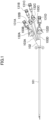
FIG. 1 is a side view of an entire quadruple-lumen catheter according to one embodiment. -
FIG. 2 is a perspective view of the entire quadruple-lumen catheter according to the embodiment. -
FIG. 3 is a perspective view of the entire quadruple-lumen catheter according to the embodiment. -
FIG. 4 is a right-side view of the quadruple-lumen catheter according to the embodiment. -
FIG. 5 is a left-side view of the quadruple-lumen catheter according to the embodiment. -
FIG. 6 is a top view of the quadruple-lumen catheter of the embodiment. -
FIG. 7 is a bottom view of the quadruple-lumen catheter of the embodiment. -
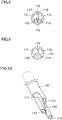
FIG. 8 is a view of the quadruple-lumen catheter ofFIG. 7 viewed from its distal end. -
FIG. 9 is a view of the quadruple-lumen catheter ofFIG. 7 viewed from its proximal end. -
FIG. 10 is a perspective view of the quadruple-lumen catheter according to the embodiment. -
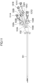
FIG. 11 is a side view of an entire quadruple-lumen catheter according to a variation. -
FIG. 12 is a side view of the entire quadruple-lumen catheter according to the variation. -
FIG. 13 is a right-side view of the quadruple-lumen catheter according to the variation. -
FIG. 14 is a left-side view of the quadruple-lumen catheter according to the variation. -
FIG. 15 is a top view of the quadruple-lumen catheter according to the variation. -
FIG. 16 is a bottom view of the quadruple-lumen catheter according to the variation. -
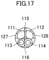
FIG. 17 is a view of the quadruple-lumen catheter according to the variation viewed from its distal end. - A quadruple-lumen catheter of the present disclosure is for use in performing administration of drug solution, measurement of central venous pressure, or the like concurrently when performing blood purification by hemodialysis using a blood removal lumen and a blood return lumen. As illustrated in
FIGS. 1 to 10 , the quadruple-lumen catheter of the present disclosure includes: a cylindrical body (a catheter tube) 101 surrounded by anouter wall 116. Apartition 115 extending in a longitudinal direction is provided inside thebody 101. Thepartition 115 divides an inner space of thebody 101 into afirst region 117 and asecond region 118. Thefirst region 117 is divided into afirst lumen 111 and athird lumen 113, and thesecond region 118 is divided into asecond lumen 112 and afourth lumen 114. During normal forward connection, thefirst lumen 111 serves as a blood removal lumen, and thesecond lumen 112 serves as a blood return lumen. During a reverse connection in which the blood removal lumen and the blood return lumen are switched to solve sticking to the blood vessel wall, thefirst lumen 111 serves as a blood return lumen, and thesecond lumen 112 serves as a blood removal lumen. Thethird lumen 113 and thefourth lumen 114 serve as an infusion lumen to be used as routes for administration of drug solution, measurement of central venous pressure, or the like. - The
third lumen 113 and thefourth lumen 114 are each circular in cross section, and thethird lumen 113 and thefourth lumen 114, being on one of sides where theouter wall 116 and thepartition 115 are in contact with each other, are positioned to face each other with thepartition 115 interposed therebetween. Thefirst lumen 111 and thesecond lumen 112 are positioned to face each other with thepartition 115 interposed therebetween. In such a configuration, thethird lumen 113, which serves as an infusion lumen, is provided in thefirst region 117, and thefourth lumen 114, which serves as the other infusion lumen, is provided in thesecond region 118. This allows to have thefirst lumen 111 and thesecond lumen 112 with larger cross-sectional areas, while two infusion lumens are provided. Therefore, even when either thefirst lumen 111 or thesecond lumen 112 is used as the blood removal lumen, the amount of blood removed can be secured and the suction pressure can be lowered to make the sticking of the blood vessel difficult. Further, thefirst lumen 111 and thesecond lumen 112, and thethird lumen 113 and thefourth lumen 114 are symmetrically formed, in pair, with thepartition 115 interposed therebetween. This facilitates extrusion molding for producing the quadruple-lumen catheter. - The distal ends of the
first lumen 111, thesecond lumen 112, thethird lumen 113, and thefourth lumen 114 are of an end hole-type with an opening at the distal end, thereby forming afirst opening plane 121, asecond opening plane 122, athird opening plane 123, and afourth opening plane 124, respectively. At thefirst opening plane 121, theouter wall 116 is so trimmed that theouter wall 116 becomes farther from thepartition 115 toward the proximal end. Thus, thefirst opening plane 121 is inclined toward the proximal end with respect to thepartition 115. Thesecond opening plane 122 is provided more distally than thefirst opening plane 121, and, at thesecond opening plane 122, theouter wall 116 is so trimmed that theouter wall 116 becomes farther from thepartition 115 toward the proximal end. Thus, thesecond opening plane 122 is inclined toward the proximal end with respect to thepartition 115. Thethird opening plane 123 is provided more distally than thesecond opening plane 122, and, at thethird opening plane 123, theouter wall 116 is so trimmed that theouter wall 116 becomes farther from thepartition 115 toward the proximal end. Thus, thethird opening plane 123 is inclined toward the proximal end with respect to thepartition 115. Thefourth opening plane 124 is provided more distally than thethird opening plane 123, and located at the distal end of thebody 101, and thefourth opening plane 124 is orthogonal to thepartition 115. - Although the use of the quadruple-lumen catheter of the present embodiment is not limited in terms of which direction is the upward, downward, rightward, or leftward direction of the quadruple-lumen catheter, the following description assumes that, with respect to the
partition 115, the upper side is the side on which thefirst region 117 provided with thefirst lumen 111, and the lower side is the side on which asecond region 118 provided with thethird lumen 113 is located, and the right side is the side on which thefirst lumen 111 and thesecond lumen 112 are located, while the left side is the side on which thethird lumen 113 and thefourth lumen 114 are located, when thebody 101 is viewed from the distal end with thefirst region 117 on the upper side. - In the quadruple-lumen catheter of the present embodiment, the
partition 115 is provided between thefirst lumen 111 and thesecond lumen 112, and thepartition 115 extends toward the distal end beyond thefirst opening plane 121 of thefirst lumen 111. Thus, during the reverse connection, blood which returns through thefirst lumen 111 to flow above thepartition 115 is less likely to be sucked via thesecond opening plane 122 below thepartition 115, thereby making it difficult for the recirculation to occur. The making it difficult to cause the recirculation is advantageous not only in the case where the reverse connection is intentionally performed to resolve the sticking to the blood vessel wall, but also in the case of erroneous reverse connection. - Moreover, the
partition 115 extends toward the distal end of thebody 101 beyond the position of thesecond opening plane 122, and, from the position of thesecond opening plane 122 to the distal end, thepartition 115 becomes narrower in width toward the left side on which thethird lumen 123 and thefourth lumen 124 are disposed, and disappears at the distal end. This makes it easy to inset the catheter by the Seldinger technique or the like, and also makes thepartition 115 less damaging to the blood vessel. In the present embodiment, thepartition 115 has a width gradually narrowed toward the distal end from the position of thesecond opening plane 122. However, in view of preventing recirculation, thepartition 115 has a width gradually narrowed toward the distal end from somewhere between thesecond opening plane 122 and the distal end. - For the blood removal via the
first lumen 111, it is preferable that thefirst opening plane 121 be located as far away from thethird opening plane 123 and thefourth opening plane 124 as possible for the sake of avoiding recirculation of the drug solution supplied through thethird lumen 113 and thefourth lumen 114. In view of the length of the catheter, it is preferable that the distance from the distal end of thebody 101 be not too long. More specifically, a distance L1 from the distal end (the fourth opening plane 124) of thebody 101 to thefirst opening plane 121 is preferably 1 cm or longer, or more preferably 1.5 cm or longer, but preferably 10 cm or shorter, more preferably 5 cm or shorter, or yet more preferably 3 cm or shorter. - The
first opening plane 121 is inclined toward the proximal end with respect to thepartition 115. The inclination of thefirst opening plane 121 toward the proximal end can reduce insertion resistance in intracorporeally inserting the catheter by the Seldinger technique or the like, whereby the insertion of the catheter can be smooth, as compared with the case where thefirst opening plane 121 is orthogonal to thepartition 115. Further, the inclination also makes thefirst opening plane 121 less damaging to the blood vessel. Further, the inclination gives the first opening plane 121 a larger size (a larger opening plane area) than that in the case where thefirst opening plane 121 is orthogonal to thepartition 115. This makes it easier to ensure the blood flow rate and lower of the suction pressure in removing the blood through thefirst lumen 111. - To be less damaging to the blood vessel, the
first opening plane 121 has an inclination angle θ1 that may be preferably 60° or less, more preferably 50° or less, or yet more preferably 40° or less. On the other hand, for performing the blood removal through thefirst lumen 111 in such a way that the wall of the blood vessel is prevented from sticking to thefirst opening plane 121 due to the suction pressure caused by the blood removal and consequently closing thefirst opening plane 121, the inclination angle θ1 may be preferably 10° or more, or more preferably 15° or more. - It is preferable that the
second opening plane 122 be located as far away from thefirst opening plane 121 as possible in light of preventing recirculation between thefirst lumen 111 and thesecond lumen 112. On the other hand, it is preferable that thesecond lumen 112 be located as far away from also thethird opening plane 123 as possible in light of preventing recirculation between thesecond lumen 112 used as a blood removal lumen during reverse connection and thethird lumen 113. Thus, a distance L1 - L2 between thefirst opening plane 121 and thesecond opening plane 122 may be preferably 10% or more, more preferably 20% or more, and preferably 60% or less, or more preferably 50% or less of the distance L1 between thefirst opening plane 121 and thefourth opening plane 124. - Similarly to the
first opening plane 121, thesecond opening plane 122 is inclined toward the proximal end with respect to thepartition 115. This reduces the insertion resistance in intracorporeally inserting the catheter by the Seldinger technique or the like, whereby the insertion of the catheter can be smooth, as compared with the case where thesecond opening plane 122 is orthogonal to thepartition 115. Further, the inclination makes thesecond opening plane 122 less damaging to the blood vessel. Further, the inclination gives the second opening plane 122 a larger size (a larger opening plane area) than that in the case where thesecond opening plane 122 is orthogonal to thepartition 115. This makes it easier to ensure the blood flow rate in removing the blood through thesecond lumen 112, and allows lowering the suction pressure. Thesecond opening plane 122 and thefirst opening plane 121 may be identical in size in consideration of using thesecond lumen 112 as a blood removal lumen. - An inclination angle θ2 of the
second opening plane 122 may be preferably 60° or less, more preferably 50° or less, or yet more preferably 40° or less. The inclination angle θ2 may be preferably 10° or more, or more preferably 15° or more in light of making it possible to remove blood through thesecond lumen 112. - It is preferable that the
third opening plane 123 be located as far away from thefirst opening plane 121 and thesecond opening plane 122 as possible in light of preventing recirculation between thefirst lumen 111 serving as a blood removal lumen during forward connection and thethird lumen 113 and between thesecond lumen 112 serving as a blood removal lumen during reverse connection and thethird lumen 113. Thus, a distance L1 - L3 between thefirst opening plane 121 and thethird opening plane 123 may be preferably 30% or more, or more preferably 40% or more, but preferably 70% or less, or more preferably 60% or less of the distance L1 between thefirst opening plane 121 and thefourth opening plane 124. Moreover, a distance L2 - L3 between thesecond opening plane 122 and thethird opening plane 123 may be preferably 10% or more, or more preferably 25% or more, but preferably 70% or less, or more preferably 60% or less of the distance L2 between thesecond opening plane 122 and thefourth opening plane 124. - Similarly to the
first opening plane 121 and thesecond opening plane 122, thethird opening plane 123 is inclined toward the proximal end with respect to thepartition 115. This reduces the insertion resistance in intracorporeally inserting the catheter into the subject's body by the Seldinger technique or the like, whereby the insertion of the catheter can smooth, as compared with the case where thethird opening plane 123 is orthogonal to thepartition 115. Further, the inclination makesthird opening plane 123 less damaging to the blood vessel. The inclination angle θ3 of thethird opening plane 123 may be preferably 70° or less, more preferably 60° or less, or yet more preferably 50° or less. The inclination angle θ1 of thefirst opening plane 121, the inclination angle θ2 of thesecond opening plane 122, and the inclination angle θ3 of thethird opening plane 123 may be identical to or different from one another. - The
fourth lumen 114 has a circular cross-sectional outer shape at the distal end of thebody 101. This makes thefourth lumen 114 less damaging to the blood vessel, as compared with the case where thefourth lumen 114 has an angular cross-sectional outer shape. Thefourth lumen 114 has such an outer diameter between the distal end and thethird opening plane 123 that may be preferably 1 mm or greater, or more preferably 1.5 mm or greater, but preferably 4 mm or smaller, or more preferably 3 mm or smaller in light of the ease insertion of the catheter. - In the quadruple-lumen catheter of the present embodiment, the
third opening plane 123 and thefourth opening plane 124 are located more distally than thesecond opening plane 122. Accordingly, when thesecond lumen 112 serves as a blood return lumen during the forward connection, a drug solution supplied through thethird lumen 113 and thefourth lumen 114 is carried by the blood flow through the blood vessel and blood flowing out of thesecond opening plane 122, and flows away from thefirst opening plane 121 through which blood is removed. This makes it difficult to cause recirculation of the drug solution. On the other hand, even when thesecond lumen 112 in thesecond region 118 serves as a blood removal lumen during the reverse connection, the location of thethird opening plane 123 being in thefirst region 117 which is on the opposite side to thesecond region 118 across thepartition 115 results in that a drug solution supplied through thethird lumen 113 is carried by the blood flow flowing out of thefirst opening plane 121, and flows away from thesecond opening plane 122 through which blood is removed. This makes it difficult to cause recirculation of the drug solution. Further, thefourth opening plane 124 is located at the distal end of thebody 101. Thus, even when thesecond lumen 112 serves as a blood removal lumen during the reverse connection, the drug solution supplied through thefourth lumen 114 is carried by the blood flow through the blood vessel and the blood flow flowing out of thefirst opening plane 121 and through thefirst region 117, and flows away from thesecond opening plane 122 through which blood is removed. This makes it difficult to cause recirculation of the drug solution. - In the quadruple-lumen catheter according to the present embodiment, the
third lumen 113 and thefourth lumen 114 are provided in the vicinity of a portion where theouter wall 116 of thebody 101 and thepartition 115 are in contact with each other, in such a way that thethird lumen 113 and thefourth lumen 114 face each other with thepartition 115 interposed therebetween, and are disposed on one side (the left side) of thebody 101. This makes it possible to provide thethird opening plane 123 at a position more distal than thesecond opening plane 122, while gradually narrowing the width of a portion of thepartition 115 from thesecond opening plane 122 toward the distal end. Thus, the quadruple-lumen catheter can be easily inserted into the blood vessel. Thesecond opening plane 122 and thethird opening plane 123 are arranged on opposite sides with respect to the central axis of thebody 101, thereby being distanced from each other. Thus, recirculation is less likely to occur even in reverse connection. If thethird lumen 113 and thefourth lumen 114 are arranged opposite sides with respect to the central axis of thebody 101, it is necessary to separate thesecond opening plane 122 and thethird opening plane 123 from each other by thepartition 115 in order to prevent recirculation during reverse connection. Thus, thethird opening plane 123 cannot be provided closer to the distal end than thesecond opening plane 122, while gradually narrowing the width of a portion of thepartition 115 from thesecond opening plane 122 toward the distal end. - When blood is removed through the
first lumen 111 and returns through thesecond lumen 112, the cross-sectional area of thefirst lumen 111 is preferably as large as possible to easily ensure the blood flow rate. However, in light of making it possible to remove blood also through thesecond lumen 112, the ratio of the cross-sectional area of thesecond lumen 112 to the cross-sectional area of thefirst lumen 111 may be preferably 0.6 or more, or more preferably 0.7 or more. The ratio of the cross-sectional area of thesecond lumen 112 to the cross-sectional area of thefirst lumen 111 may be 1, but may be preferably 0.95 or less, or more preferably 0.9 or less in light of ensuring the rate of blood removed through thefirst lumen 111. The cross-sectional area of thefirst region 117 and the cross-sectional area of thesecond region 118 into which the inside of thebody 101 is divided by thepartition 115 may be identical with each other, but the cross-sectional area of thefirst region 117 may be larger than the cross-sectional area of thesecond region 118 in light of increasing the cross-sectional area of thefirst lumen 111. - The cross-sectional areas of the
first lumen 111 and thesecond lumen 112 and the sizes (the areas of the opening plane) of thefirst opening plane 121 and thesecond opening plane 122 may be such that the cross-sectional areas of thefirst lumen 111 and thesecond lumen 112 differ from each other, while the sizes of thefirst opening plane 121 and thesecond opening plane 122 are identical with each other. As an alternative, these may be so configured that the cross-sectional areas of thefirst lumen 111 and thesecond lumen 112 are identical with each other, while the sizes of thefirst opening plane 121 and thesecond opening plane 122 are identical with each other. - It is preferable that the
first lumen 111 have such a cross-sectional area that is as large as possible in a portion of thefirst region 117 where thethird lumen 113 is not present. Thus, thefirst lumen 111 may have a cross section other than a circular cross section. For example, the cross-sectional shape of thefirst lumen 111 may be a substantially circular shape such as an elliptical shape, a sector shape, or shapes distorted therefrom, in accordance with the shape of the portion of thefirst region 117 where thethird lumen 113 is not present. Similarly, it is preferable that thesecond lumen 112 has such a cross-sectional area that is as large as possible in a portion of thesecond region 118 where thefourth lumen 114 is not present. Therefore, thesecond lumen 112 may have a substantially circular cross section in accordance with the shape of the portion of thesecond region 118 where thefourth lumen 114 is not present. The configuration in which thefirst lumen 111 and thesecond lumen 112 each are substantially circular in cross section can provide efficient utilization of the lumen of thebody 101, and allows both thefirst lumen 111 and thesecond lumen 112 to be large in cross-sectional area. At least either one of thefirst lumen 111 or thesecond lumen 112 may have a circular cross section. - On the other hands, because the
third lumen 113 and thefourth lumen 114 which each serve as an infusion lumen do not require a large flow rate, the cross-sectional areas of thethird lumen 113 and thefourth lumen 114 are smaller than the cross-sectional areas of thefirst lumen 111 and thesecond lumen 112, and may be preferably 0.1 or more, more preferably 0.25 or more, and preferably 0.5 or less, more preferably 0.35 or less. The cross-sectional areas of thethird lumen 113 and thefourth lumen 114 may be identical from each other, but the ratio of the cross-sectional area of thethird lumen 113 to the cross-sectional area of thefourth lumen 114 may be changed within the range of about 0.5 to about 1.5 according to the intended use of each lumen. - The configuration in which the
third lumen 113 and thefourth lumen 114 are each circular in cross section can reduce the resistance of fluid, thereby facilitating pumping, and also makes it easy to form thethird lumen 113 and thefourth lumen 114. However, thethird lumen 113 and thefourth lumen 114 may not be circular in cross section, and may be substantially circular in cross section. - The distal end portion of the
first lumen 111 may be provided with a firstlumen side pore 125 or first lumen side pores 125 communicating between thefirst lumen 111 and the outside. This configuration can reduce the suction pressure at thefirst opening plane 121 when thefirst lumen 111 serves as a blood removal lumen, thereby preventing the inner wall of the blood vessel from sticking to thefirst opening plane 121. Further, this configuration makes is possible to easily ensure the removal blood flow rate. - It is preferable to provide a plurality of the first lumen side pores 125 in order to attain a greater effect of dispersing the suction pressure. The number of first lumen side pores 125 is not particularly limited, but it is preferable to provide two first lumen side pores 125 each on an upper side and a right side of the
first lumen 111. However, the first lumen side pores 125 may be provided as needed and may be omitted. - The distal end portion of the
second lumen 112 may be provided with a secondlumen side pore 126 or second lumen side pores 126 communicating between thesecond lumen 112 and the outside. This configuration can reduce the suction pressure at thesecond opening plane 122 when thesecond lumen 112 serves as a blood removal lumen, thereby preventing the inner wall of the blood vessel from sticking to thesecond opening plane 122. Further, this configuration makes it possible to easily ensure the removal blood flow rate. - It is preferable to provide a plurality of the second lumen side pores 126 in order to attain a greater effect of dispersing the suction pressure. The number of second lumen side pores 126 is not particularly limited, but it is preferable to provide two
second lumens 112 each on an upper side and a right side of thesecond lumen 112. However, the second lumen side pores 126 may be provided as needed and may be omitted. - The length of the
body 101 is not particularly limited, but may be preferably 10 cm or longer, or more preferably 13 cm or longer, but preferably 40 cm or shorter, or more preferably 30 cm or shorter. - The outer diameter of the
body 101 is not particularly limited, but may be preferably 3 mm or greater, or more preferably 4 mm or greater in light of ensuring the blood flow rate. Moreover, for being insertable into the blood vessel, the outer diameter of thebody 101 may be preferably 6 mm or smaller, or more preferably 5 mm or smaller. - The thickness of the
outer wall 116 of thebody 101 is not particularly limited, but is preferably 0.1 mm or more, more preferably 0.2 mm or more, and preferably 0.8 mm or less, more preferably 0.6 mm or less in light of the strength and flexibility of the catheter. - The
body 101 may be formed of a material which is hard enough to maintain a stable shape in the blood vessel and but soft enough not to damage the blood vessel, such as polyurethane, polyvinyl chloride, silicone, polyethylene, polypropylene, an ethylene-vinyl acetate copolymer, or a polyamide. The material of thebody 101 is particularly preferably polyurethane, which maintains such a hardness that does not impair the ease of insertion of the catheter and becomes harder at normal temperatures and softer at internal body temperatures. A distal end portion of thebody 101, e.g., a portion of thebody 101 between the distal end and thesecond opening plane 122 may be configured to be less damaging to blood vessels by being softer than the rest of thebody 101. At least a portion of thebody 101 may be formed of a material containing a contrast agent such as barium sulfate, bismuth tungstate, or bismuth oxide, so as to facilitate finding out where thebody 101 is inserted. For example, by configuring such that the distal end of thebody 101 has a color different from the color of the other portion of thebody 101, the position of the distal end portion of thebody 101 can be easily recognizable. - The
body 101 is provided withbranch pipes 103A to 103D extending from the proximal end of thebody 101 via abranch portion 102. Distal ends of thebranch pipes 103A to 103D are connected to thefirst lumen 111 to thefourth lumen 114, respectively. Each of the proximal ends of thebranch pipes 103A to 103D is provided with a connector (not shown) connected thereto. The connectors, which are covered respectively withprotection caps 131A to 131D in the illustrations inFIGS. 1 to 3 , allow thebody 101 to be connected to a blood circuit and the like via the connectors. Thebranch pipes 103A to 103D are provided respectively withclamps 132A to 132D attached thereto. With theclamps 132A to 132D, thebranch pipes 103A to 103D can be closable for performing a treatment such as heparin rock. - The quadruple-lumen catheter of the present embodiment may be biocompatible-treated on at least one of an inner surface or an outer surface thereof with a biocompatible treatment of various types. For example, the quadruple-lumen catheter of the present embodiment may be antithrombotic-surfaced so as to prevent thrombus formation due to contact with blood during indwelling. The antithrombotic surfacing is not particularly limited and may be carried out by any methods such as a method of immobilizing a plasminogen activator such as urokinase or a method of immobilizing an anticoagulant such as heparin.
- The catheter according to the present embodiment can be modified in various ways. In the following variations, only portions different from the present embodiment will be described. The description of the configuration common to the present embodiment will be omitted as appropriate. In addition, like portions are denoted with like reference numerals as in the present embodiment.
- As a variation of the catheter according to the present embodiment, as shown in
FIGS. 11 to 17 , a first lumen slit 127 notching a portion of the distal end may be provided in a portion of theouter wall 116 where thefirst lumen 111 is provided. Further, a second lumen slit 128 notching a portion of the distal end may be provided in a portion of theouter wall 116 where thesecond lumen 112 is provided. - With such a configuration, the flow of blood sucked into the
first lumen 111 is dispersed also into the first lumen slit 127 during forward connection. This reduces the suction pressure, thereby making it difficult to cause sticking to the blood vessel wall. With this configuration, even if thefirst opening plane 121 is clogged due to thrombus or the like, thefirst lumen 111 can be kept open. Further, with the second lumen slit 128, the same effect as in the configuration with the first lumen slit 127 can be obtained during the reverse connection. - Moreover, the
body 101 may be so configured that the distal end portion of thebody 101, e.g., a portion of theouter wall 116 between the distal end and a proximal end of the first lumen slit 127 is softer than the rest of thebody 101 excluding the distal end portion. The configuration in which the first lumen slit 127 and the second lumen slit 128 notching portions of the distal end of theouter wall 116 are provided makes theouter wall 116 more easily deformable, but the configuration in which the distal end portion of theouter wall 116 is softer makes theouter wall 116 even more easily deformable. These configurations bring about such an effect that, when the catheter is inserted, theouter walls 116 forming thefirst lumen 111 and thesecond lumen 112 are easily deformed by bending inwardly toward the inside of thefirst lumen 111 and the inside of thesecond lumen 112. This provides such an excellent insertability to the catheter that, at inserting the catheter, the cross-sectional areas of thebody 101 at thefirst opening plane 121 and thesecond opening plane 122 become smaller, thereby avoiding a sudden increase in insertion resistance. - The length L4 of the first lumen slit 127 and the length L5 of the second lumen slit 128 are not particularly limited, but may be preferably 2 mm or more but 15 mm or less, or more preferably 5 mm or more but 10 mm or less in light of reducing sticking of the catheter to the blood vessel wall. The length L4 of the first lumen slit 127 and the length L5 of the second lumen slit 128 may be identical to or different from each other.
- It is sufficient that the widths of the first lumen slit 127 and the second lumen slit 128 are as predetermined. The widths of the first lumen slit 127 and the second lumen slit 128 are not particularly limited, and may be preferably 0.1 mm or more but 2.5 mm or less, or more preferably 0.5 mm or more but 2.0 mm or less in light of ensuring rigidity of the
outer wall 116. The widths of the first lumen slit 127 and the second lumen slit 128 may be identical to or different from each other. - The first lumen slit 127 and the second lumen slit 128 illustrated in
FIGS. 15 and 16 each are constant in width in the longitudinal direction, but the width is not limited to this, and the width may change in the longitudinal direction. For example, the first lumen slit 127 or the second lumen slit 128 may become wider gradually from its distal end to its proximal end. - Although the above discusses a variation in which the quadruple-lumen catheter is configured with the first lumen slit 127 and the second lumen slit 128, but the quadruple-lumen catheter may be configured with either the first lumen slit 127 or the second lumen slit 128.
- A quadruple-lumen catheter of the present disclosure makes it difficult to cause recirculation of blood and a drug solution even when blood is removed through the blood return lumen due to resolution of sticking to the inner wall of the blood vessel, an erroneous connection, or the like.
-
- 101
- Body
- 102
- Branch Portion
- 103A
- Branch Pipe
- 103B
- Branch Pipe
- 103C
- Branch Pipe
- 111
- First Lumen
- 112
- Second Lumen
- 113
- Third Lumen
- 114
- Fourth Lumen
- 115
- Partition
- 116
- Outer Wall
- 117
- First Region
- 118
- Second Region
- 121
- First opening plane
- 122
- Second opening plane
- 123
- Third opening plane
- 124
- Fourth opening plane
- 125
- First Lumen Side Pore
- 126
- Second Lumen Side Pore
- 127
- First Lumen Slit
- 128
- Second Lumen Slit
- 131A
- Protective Cap
- 131B
- Protective Cp
- 131C
- Protective Cp
- 131D
- Protective Cp
- 132A
- Clamp
- 132B
- Clamp
- 132C
- Clamp
- 132D
- Clamp
Claims (8)
- A quadruple-lumen catheter, comprising:a cylindrical body extending from a proximal end to a distal end and being surrounded by an outer wall,the body having an inner space divided into a first region and a second region by a partition extending in a longitudinal direction,the first region being divided into a first lumen and a third lumen being smaller in cross-sectional area than the first lumen,the second region being divided into a second lumen and a fourth lumen being smaller in cross-sectional area than the second lumen,the third lumen and the fourth lumen facing each other with the partition interposed therebetween,the second lumen having a second opening plane at its distal end, and the first lumen having a first opening plane at its distal end, and the second opening plane being more distal than the first opening plane,the third lumen having a third opening plane at its distal end, and the third opening plane being more distal than the second opening plane,the fourth lumen having a fourth opening plane at its distal end, and the fourth opening plane being more distal than the third opening plane, andthe partition being such that, between the distal end of the body and the second opening plane, a width of the partition is gradually narrowed toward the third lumen and the fourth lumen.
- The quadruple-lumen catheter of claim 1, wherein
the first lumen and the second lumen are symmetrical with respect to the partition, and the third lumen and the fourth lumen are symmetrical with respect to the partition. - The quadruple-lumen catheter of claim 1 or 2, wherein
the first opening plane and the second opening plane are identical in size. - The quadruple-lumen catheter of any one of claims 1 to 3, whereinthe first opening plane, the second opening plane, and the third opening plane are inclined toward the proximal end of the body with respect to the partition, andthe fourth opening plane is orthogonal to the partition.
- The quadruple-lumen catheter of any one of claims 1 to 4, wherein
a portion of the body between the distal end thereof and the second opening plane has a lower hardness than a portion of the body between the second opening plane and the proximal end. - The quadruple-lumen catheter of any one of claims 1 to 5, comprising:
a plurality of branch pipes provided to the proximal end of the body, the plurality of branch pipes being connected respectively to the first lumen, the second lumen, the third lumen, and the fourth lumen and being each provided with a connector at a proximal end thereof. - The quadruple-lumen catheter of any one of claims 1 to 6, whereinthe first lumen has a plurality of first lumen side pores in its distal end portion, andthe second lumen has a plurality of second lumen side pores in its distal end portion.
- The quadruple-lumen catheter of any one of claims 1 to 7, wherein
the outer wall has, in a portion where the first lumen is provided, a first lumen slit notching a distal end of the outer wall and/or in a portion where the second lumen is provided, a second lumen slit notching the distal end.
Applications Claiming Priority (2)
| Application Number | Priority Date | Filing Date | Title |
|---|---|---|---|
| JP2020089928 | 2020-05-22 | ||
| PCT/JP2021/015069 WO2021235135A1 (en) | 2020-05-22 | 2021-04-09 | Quadruple-lumen catheter |
Publications (4)
| Publication Number | Publication Date |
|---|---|
| EP4144395A1 true EP4144395A1 (en) | 2023-03-08 |
| EP4144395A4 EP4144395A4 (en) | 2023-12-06 |
| EP4144395C0 EP4144395C0 (en) | 2024-11-06 |
| EP4144395B1 EP4144395B1 (en) | 2024-11-06 |
Family
ID=78707795
Family Applications (1)
| Application Number | Title | Priority Date | Filing Date |
|---|---|---|---|
| EP21809685.7A Active EP4144395B1 (en) | 2020-05-22 | 2021-04-09 | Quadruple-lumen catheter |
Country Status (3)
| Country | Link |
|---|---|
| EP (1) | EP4144395B1 (en) |
| JP (1) | JP7571787B2 (en) |
| WO (1) | WO2021235135A1 (en) |
Cited By (1)
| Publication number | Priority date | Publication date | Assignee | Title |
|---|---|---|---|---|
| EP4782027A1 (en) * | 2025-01-22 | 2026-07-29 | Abiomed, Inc. | Devices and methods for detecting mixing cloud locations |
Family Cites Families (6)
| Publication number | Priority date | Publication date | Assignee | Title |
|---|---|---|---|---|
| JP4945174B2 (en) * | 2006-06-23 | 2012-06-06 | ユニチカ株式会社 | 4 lumen catheter |
| US8591450B2 (en) | 2010-06-07 | 2013-11-26 | Rex Medical L.P. | Dialysis catheter |
| US9717883B2 (en) * | 2011-02-10 | 2017-08-01 | C. R. Bard, Inc. | Multi-lumen catheter with enhanced flow features |
| JP2016022192A (en) * | 2014-07-22 | 2016-02-08 | ニプロ株式会社 | catheter |
| US20170273628A1 (en) | 2016-03-24 | 2017-09-28 | C. R. Bard, Inc. | Catheter Assembly Including Transitioning Lumens |
| JP7106970B2 (en) | 2017-05-26 | 2022-07-27 | ニプロ株式会社 | triple lumen catheter |
-
2021
- 2021-04-09 WO PCT/JP2021/015069 patent/WO2021235135A1/en not_active Ceased
- 2021-04-09 EP EP21809685.7A patent/EP4144395B1/en active Active
- 2021-04-09 JP JP2022524327A patent/JP7571787B2/en active Active
Cited By (1)
| Publication number | Priority date | Publication date | Assignee | Title |
|---|---|---|---|---|
| EP4782027A1 (en) * | 2025-01-22 | 2026-07-29 | Abiomed, Inc. | Devices and methods for detecting mixing cloud locations |
Also Published As
| Publication number | Publication date |
|---|---|
| WO2021235135A1 (en) | 2021-11-25 |
| JP7571787B2 (en) | 2024-10-23 |
| EP4144395C0 (en) | 2024-11-06 |
| EP4144395B1 (en) | 2024-11-06 |
| JPWO2021235135A1 (en) | 2021-11-25 |
| EP4144395A4 (en) | 2023-12-06 |
Similar Documents
| Publication | Publication Date | Title |
|---|---|---|
| US5403291A (en) | Catheter with elongated side holes | |
| US7556612B2 (en) | Dual-lumen bi-directional flow catheter | |
| EP2564886B1 (en) | Dialysis catheter | |
| EP3687615B1 (en) | Peripheral intravenous catheters having flow diverting features | |
| US6808510B1 (en) | Multi-lumen catheter and tip configurations for use therewith | |
| US8496607B2 (en) | Multi-lumen catheter | |
| CN101056667B (en) | Triple lumen catheter | |
| US20080154186A1 (en) | Multiple lumen catheter with proximal port | |
| JP6076590B2 (en) | Dialysis catheter | |
| EP1313527B1 (en) | Multi-lumen catheter and tip configurations for use therewith | |
| AU2001288475A1 (en) | Multi-lumen catheter and tip configurations for use therewith | |
| WO2009131583A1 (en) | Catheter with open faced beveled tip | |
| US8876752B2 (en) | Dialysis catheter | |
| JP7106970B2 (en) | triple lumen catheter | |
| JP2001340466A (en) | Double lumen catheter | |
| EP4144395B1 (en) | Quadruple-lumen catheter | |
| JP4945174B2 (en) | 4 lumen catheter | |
| EP4233960B1 (en) | Multilumen catheter | |
| JP2007202901A (en) | Triple lumen catheter | |
| JP2016022192A (en) | catheter | |
| US8708956B2 (en) | Multi-lumen catheter with protected tip | |
| JP4832011B2 (en) | Triple lumen catheter | |
| JP7796532B2 (en) | double lumen catheter | |
| JP5840866B2 (en) | Dialysis catheter | |
| EP1534372B1 (en) | Shielded tip catheter |
Legal Events
| Date | Code | Title | Description |
|---|---|---|---|
| STAA | Information on the status of an ep patent application or granted ep patent |
Free format text: STATUS: THE INTERNATIONAL PUBLICATION HAS BEEN MADE |
|
| PUAI | Public reference made under article 153(3) epc to a published international application that has entered the european phase |
Free format text: ORIGINAL CODE: 0009012 |
|
| STAA | Information on the status of an ep patent application or granted ep patent |
Free format text: STATUS: REQUEST FOR EXAMINATION WAS MADE |
|
| 17P | Request for examination filed |
Effective date: 20221129 |
|
| AK | Designated contracting states |
Kind code of ref document: A1 Designated state(s): AL AT BE BG CH CY CZ DE DK EE ES FI FR GB GR HR HU IE IS IT LI LT LU LV MC MK MT NL NO PL PT RO RS SE SI SK SM TR |
|
| DAV | Request for validation of the european patent (deleted) | ||
| DAX | Request for extension of the european patent (deleted) | ||
| A4 | Supplementary search report drawn up and despatched |
Effective date: 20231106 |
|
| RIC1 | Information provided on ipc code assigned before grant |
Ipc: A61M 25/14 20060101ALI20231030BHEP Ipc: A61M 25/00 20060101AFI20231030BHEP |
|
| GRAP | Despatch of communication of intention to grant a patent |
Free format text: ORIGINAL CODE: EPIDOSNIGR1 |
|
| STAA | Information on the status of an ep patent application or granted ep patent |
Free format text: STATUS: GRANT OF PATENT IS INTENDED |
|
| INTG | Intention to grant announced |
Effective date: 20240812 |
|
| GRAS | Grant fee paid |
Free format text: ORIGINAL CODE: EPIDOSNIGR3 |
|
| GRAA | (expected) grant |
Free format text: ORIGINAL CODE: 0009210 |
|
| STAA | Information on the status of an ep patent application or granted ep patent |
Free format text: STATUS: THE PATENT HAS BEEN GRANTED |
|
| AK | Designated contracting states |
Kind code of ref document: B1 Designated state(s): AL AT BE BG CH CY CZ DE DK EE ES FI FR GB GR HR HU IE IS IT LI LT LU LV MC MK MT NL NO PL PT RO RS SE SI SK SM TR |
|
| REG | Reference to a national code |
Ref country code: GB Ref legal event code: FG4D |
|
| REG | Reference to a national code |
Ref country code: CH Ref legal event code: EP |
|
| REG | Reference to a national code |
Ref country code: DE Ref legal event code: R096 Ref document number: 602021021563 Country of ref document: DE |
|
| REG | Reference to a national code |
Ref country code: IE Ref legal event code: FG4D |
|
| U01 | Request for unitary effect filed |
Effective date: 20241121 |
|
| U07 | Unitary effect registered |
Designated state(s): AT BE BG DE DK EE FI FR IT LT LU LV MT NL PT RO SE SI Effective date: 20241128 |
|
| PG25 | Lapsed in a contracting state [announced via postgrant information from national office to epo] |
Ref country code: IS Free format text: LAPSE BECAUSE OF FAILURE TO SUBMIT A TRANSLATION OF THE DESCRIPTION OR TO PAY THE FEE WITHIN THE PRESCRIBED TIME-LIMIT Effective date: 20250306 Ref country code: HR Free format text: LAPSE BECAUSE OF FAILURE TO SUBMIT A TRANSLATION OF THE DESCRIPTION OR TO PAY THE FEE WITHIN THE PRESCRIBED TIME-LIMIT Effective date: 20241106 |
|
| PG25 | Lapsed in a contracting state [announced via postgrant information from national office to epo] |
Ref country code: ES Free format text: LAPSE BECAUSE OF FAILURE TO SUBMIT A TRANSLATION OF THE DESCRIPTION OR TO PAY THE FEE WITHIN THE PRESCRIBED TIME-LIMIT Effective date: 20241106 |
|
| PG25 | Lapsed in a contracting state [announced via postgrant information from national office to epo] |
Ref country code: NO Free format text: LAPSE BECAUSE OF FAILURE TO SUBMIT A TRANSLATION OF THE DESCRIPTION OR TO PAY THE FEE WITHIN THE PRESCRIBED TIME-LIMIT Effective date: 20250206 |
|
| PG25 | Lapsed in a contracting state [announced via postgrant information from national office to epo] |
Ref country code: GR Free format text: LAPSE BECAUSE OF FAILURE TO SUBMIT A TRANSLATION OF THE DESCRIPTION OR TO PAY THE FEE WITHIN THE PRESCRIBED TIME-LIMIT Effective date: 20250207 |
|
| PG25 | Lapsed in a contracting state [announced via postgrant information from national office to epo] |
Ref country code: PL Free format text: LAPSE BECAUSE OF FAILURE TO SUBMIT A TRANSLATION OF THE DESCRIPTION OR TO PAY THE FEE WITHIN THE PRESCRIBED TIME-LIMIT Effective date: 20241106 |
|
| PG25 | Lapsed in a contracting state [announced via postgrant information from national office to epo] |
Ref country code: RS Free format text: LAPSE BECAUSE OF FAILURE TO SUBMIT A TRANSLATION OF THE DESCRIPTION OR TO PAY THE FEE WITHIN THE PRESCRIBED TIME-LIMIT Effective date: 20250206 |
|
| U20 | Renewal fee for the european patent with unitary effect paid |
Year of fee payment: 5 Effective date: 20250425 |
|
| PG25 | Lapsed in a contracting state [announced via postgrant information from national office to epo] |
Ref country code: SM Free format text: LAPSE BECAUSE OF FAILURE TO SUBMIT A TRANSLATION OF THE DESCRIPTION OR TO PAY THE FEE WITHIN THE PRESCRIBED TIME-LIMIT Effective date: 20241106 |
|
| PG25 | Lapsed in a contracting state [announced via postgrant information from national office to epo] |
Ref country code: SK Free format text: LAPSE BECAUSE OF FAILURE TO SUBMIT A TRANSLATION OF THE DESCRIPTION OR TO PAY THE FEE WITHIN THE PRESCRIBED TIME-LIMIT Effective date: 20241106 |
|
| PG25 | Lapsed in a contracting state [announced via postgrant information from national office to epo] |
Ref country code: CZ Free format text: LAPSE BECAUSE OF FAILURE TO SUBMIT A TRANSLATION OF THE DESCRIPTION OR TO PAY THE FEE WITHIN THE PRESCRIBED TIME-LIMIT Effective date: 20241106 |
|
| PLBE | No opposition filed within time limit |
Free format text: ORIGINAL CODE: 0009261 |
|
| STAA | Information on the status of an ep patent application or granted ep patent |
Free format text: STATUS: NO OPPOSITION FILED WITHIN TIME LIMIT |
|
| 26N | No opposition filed |
Effective date: 20250807 |
|
| REG | Reference to a national code |
Ref country code: CH Ref legal event code: H13 Free format text: ST27 STATUS EVENT CODE: U-0-0-H10-H13 (AS PROVIDED BY THE NATIONAL OFFICE) Effective date: 20251125 |
|
| PG25 | Lapsed in a contracting state [announced via postgrant information from national office to epo] |
Ref country code: MC Free format text: LAPSE BECAUSE OF FAILURE TO SUBMIT A TRANSLATION OF THE DESCRIPTION OR TO PAY THE FEE WITHIN THE PRESCRIBED TIME-LIMIT Effective date: 20241106 |
|
| GBPC | Gb: european patent ceased through non-payment of renewal fee |
Effective date: 20250409 |
|
| PG25 | Lapsed in a contracting state [announced via postgrant information from national office to epo] |
Ref country code: GB Free format text: LAPSE BECAUSE OF NON-PAYMENT OF DUE FEES Effective date: 20250409 |
|
| PG25 | Lapsed in a contracting state [announced via postgrant information from national office to epo] |
Ref country code: CH Free format text: LAPSE BECAUSE OF NON-PAYMENT OF DUE FEES Effective date: 20250430 |
|
| PG25 | Lapsed in a contracting state [announced via postgrant information from national office to epo] |
Ref country code: IE Free format text: LAPSE BECAUSE OF NON-PAYMENT OF DUE FEES Effective date: 20250409 |
|
| U20 | Renewal fee for the european patent with unitary effect paid |
Year of fee payment: 6 Effective date: 20260428 |
|
| PG25 | Lapsed in a contracting state [announced via postgrant information from national office to epo] |
Ref country code: CY Free format text: LAPSE BECAUSE OF FAILURE TO SUBMIT A TRANSLATION OF THE DESCRIPTION OR TO PAY THE FEE WITHIN THE PRESCRIBED TIME-LIMIT Effective date: 20241106 |