EP4144272A1 - Setting a position of at least one working member in a nozzle arrangement - Google Patents
Setting a position of at least one working member in a nozzle arrangement Download PDFInfo
- Publication number
- EP4144272A1 EP4144272A1 EP21194418.6A EP21194418A EP4144272A1 EP 4144272 A1 EP4144272 A1 EP 4144272A1 EP 21194418 A EP21194418 A EP 21194418A EP 4144272 A1 EP4144272 A1 EP 4144272A1
- Authority
- EP
- European Patent Office
- Prior art keywords
- nozzle arrangement
- working member
- value
- pushing force
- nozzle
- Prior art date
- Legal status (The legal status is an assumption and is not a legal conclusion. Google has not performed a legal analysis and makes no representation as to the accuracy of the status listed.)
- Withdrawn
Links
- 238000004140 cleaning Methods 0.000 claims abstract description 36
- 230000007246 mechanism Effects 0.000 claims abstract description 23
- 230000009471 action Effects 0.000 claims description 13
- 230000008878 coupling Effects 0.000 claims description 12
- 238000010168 coupling process Methods 0.000 claims description 12
- 238000005859 coupling reaction Methods 0.000 claims description 12
- 238000006243 chemical reaction Methods 0.000 claims description 9
- 230000003993 interaction Effects 0.000 claims description 3
- 230000008901 benefit Effects 0.000 description 3
- 238000010276 construction Methods 0.000 description 3
- 238000000034 method Methods 0.000 description 3
- 230000008569 process Effects 0.000 description 3
- 238000011109 contamination Methods 0.000 description 2
- 238000001514 detection method Methods 0.000 description 2
- 230000004048 modification Effects 0.000 description 2
- 238000012986 modification Methods 0.000 description 2
- 230000008859 change Effects 0.000 description 1
- 230000001010 compromised effect Effects 0.000 description 1
- 230000001419 dependent effect Effects 0.000 description 1
- 239000000428 dust Substances 0.000 description 1
- 230000000694 effects Effects 0.000 description 1
- 239000002245 particle Substances 0.000 description 1
- 230000002265 prevention Effects 0.000 description 1
- 238000010407 vacuum cleaning Methods 0.000 description 1
Images

Classifications
-
- A—HUMAN NECESSITIES
- A47—FURNITURE; DOMESTIC ARTICLES OR APPLIANCES; COFFEE MILLS; SPICE MILLS; SUCTION CLEANERS IN GENERAL
- A47L—DOMESTIC WASHING OR CLEANING; SUCTION CLEANERS IN GENERAL
- A47L9/00—Details or accessories of suction cleaners, e.g. mechanical means for controlling the suction or for effecting pulsating action; Storing devices specially adapted to suction cleaners or parts thereof; Carrying-vehicles specially adapted for suction cleaners
- A47L9/02—Nozzles
- A47L9/04—Nozzles with driven brushes or agitators
- A47L9/0461—Dust-loosening tools, e.g. agitators, brushes
- A47L9/0466—Rotating tools
- A47L9/0477—Rolls
-
- A—HUMAN NECESSITIES
- A47—FURNITURE; DOMESTIC ARTICLES OR APPLIANCES; COFFEE MILLS; SPICE MILLS; SUCTION CLEANERS IN GENERAL
- A47L—DOMESTIC WASHING OR CLEANING; SUCTION CLEANERS IN GENERAL
- A47L9/00—Details or accessories of suction cleaners, e.g. mechanical means for controlling the suction or for effecting pulsating action; Storing devices specially adapted to suction cleaners or parts thereof; Carrying-vehicles specially adapted for suction cleaners
- A47L9/02—Nozzles
- A47L9/06—Nozzles with fixed, e.g. adjustably fixed brushes or the like
- A47L9/066—Nozzles with fixed, e.g. adjustably fixed brushes or the like with adjustably mounted brushes, combs, lips or pads; Height adjustment of nozzle or dust loosening tools
Definitions
- the invention relates to a nozzle arrangement configured to be applied in a cleaning device and to be used in a cleaning action on a surface, wherein the nozzle arrangement: is configured to be moved forward and backward in an advancement direction of the nozzle arrangement over the surface, comprises at least one working member configured to assume one of at least two possible positions on the nozzle arrangement, and comprises a member setting mechanism configured to automatically set the position of the at least one working member.
- the invention relates to a vacuum cleaner comprising a nozzle arrangement as mentioned, which vacuum cleaner may be a cordless vacuum cleaner and/or a stick vacuum cleaner.
- Vacuum cleaners are known for removing dirt from a surface to be cleaned.
- the term "dirt" as used in the present text is to be understood so as to cover any contamination as may be present on a surface and that can be removed under the influence of a vacuum cleaning action, probably combined with another cleaning action such as mopping. Practical examples in this respect include dust and small particles of any kind, and also wet types of contamination such as spilled drinks.
- a practical example of the surface to be cleaned is a floor, wherein the floor may be of any kind, such as a wooden floor, a carpet floor, a tile floor, etc.
- a vacuum cleaner has a vacuum cleaner head, which is commonly referred to by terms such as suction head, suction nozzle, or nozzle arrangement. In the present text, the latter term will be used.
- the nozzle arrangement is the part of the vacuum cleaner where the actual process of picking up dirt from a surface to be cleaned is to take place and which is therefore to be put on or at least close to the surface.
- a vacuum cleaner normally comprises a body portion including a dirt accumulating area and an arrangement configured to act on the nozzle arrangement so that a suction force is prevailing in the nozzle arrangement during operation of the vacuum cleaner. The suction force serves to facilitate transport of dirt that is picked up from the surface during operation of the vacuum cleaner towards the dirt accumulating area.
- the suction force may also have a function in the actual process of picking up the dirt from the surface.
- the nozzle arrangement may be equipped with at least one movable component for interacting with the surface in order to pick up the dirt, such as at least one rotatable brush that may serve as an agitator of the dirt and that may particularly be configured to help dislodge dirt from the surface and direct it to further inside the nozzle arrangement.
- US 3,798,704 discloses a vacuum cleaner nozzle which has a passageway providing a path of flow for air from a suction inlet to an outlet, the suction inlet being defined by an apertured flat surface part which serves as a working member for cleaning rugs/carpets.
- a brush which serves as another working member for cleaning hard floors, is mounted on the nozzle at the vicinity of the suction in let for movement between upper and lower positions respectively above and below the suction inlet.
- the vacuum cleaner nozzle has a pair of working members, one for cleaning rugs/carpets and the other for cleaning hard floors.
- the vacuum cleaner nozzle is designed to automatically place the correct working member in cleaning position when the nozzle is moved over a rug/carpet or a hard floor.
- the working member for cleaning rugs/carpets is realized as a smooth operating member and the working member for cleaning hard floors is realized as a brush operating member.
- the smooth operating member automatically functions to perform cleaning when the flow of air in its path of flow between the suction inlet and outlet of the nozzle is at or less than a predetermined speed
- the brush operating member automatically functions to perform cleaning when the flow of air exceeds the predetermined speed.
- a type of working member which is especially configured to interact with a soft floor such as a carpet floor, and which should not be allowed to contact a hard floor in order to avoid damage to the hard floor in the form of scratches, for example.
- Nozzle arrangements are known which are configured to enable manual setting of the position of the working member, in which case appropriate action by a user is required, depending on the type of the surface to be cleaned. There is a risk that the user forgets to switch the position of the working member when another type of surface is to be cleaned, or that the user is confused about which position of the working member should go with which position of the working member and sets an incorrect position of the working member for that reason.
- nozzle arrangements are known in which the underpressure prevailing in the nozzle arrangement when the nozzle arrangement is used on a hard floor is used to lift the working member off the floor.
- the problems involved in dependency on user action are alleviated, but the fact is that relying on underpressure effects is not possible/suitable in all possible situations.
- the level of underpressure is insufficient to realize the desired setting of the working member.
- the constructions enabling use of underpressure to bring about movement of the working member require a lot of space in the nozzle arrangements and thereby significantly add to bulkiness of the nozzle arrangements.
- the invention provides a nozzle arrangement configured to be applied in a cleaning device and to be used in a cleaning action on a surface, wherein the nozzle arrangement: is configured to be moved forward and backward in an advancement direction of the nozzle arrangement over the surface, comprises at least one working member configured to assume one of at least two possible positions on the nozzle arrangement, and comprises a member setting mechanism configured to automatically set the position of the at least one working member in relation to a value of at least one discrimination parameter that is influenced by motion resistance between the nozzle arrangement and an actual surface.
- the member setting mechanism functions on the basis of another principle than using underpressure for determining the position of the at least one working member.
- the invention covers various types of working member.
- the at least one working member is configured to assume at least one active position at which the at least one working member is capable of influencing interaction between the nozzle arrangement and the surface, and an inactive position, i.e. a position at which the at least one working member is not capable of doing so. It may be so that the at least one working member is in a position for contacting the surface when the at least one working member is in the at least one active position, although this is not essential in the context of the invention.
- the member setting mechanism is configured to put the at least one working member from the inactive position to an active position when the value of the at least one discrimination parameter exceeds a reference value.
- such a reference value may be between a value of the at least one discrimination parameter related to movement of the nozzle arrangement over a hard surface and a value of the at least one discrimination parameter related to movement of the nozzle arrangement over a soft surface providing higher motion resistance than the hard surface.
- the nozzle arrangement is configured to be moved forward and backward in the advancement direction of the nozzle arrangement over the surface under the influence of an external pushing force and an external pulling force, respectively, and the at least one discrimination parameter is a parameter representative of the external pushing force.
- the external pushing force and the external pulling force may particularly be exerted by a user.
- the nozzle arrangement comprises at least one rotatable brush configured to interact with the surface, and a motor configured to drive the brush, and the at least one discrimination parameter is a parameter representative of power consumption of the motor.
- the first option is practical in view of the assumption that an increase of external pushing force is indicative of an increase of motion resistance between the nozzle arrangement and the surface
- the latter option is practical in view of the assumption that an increase of power consumption of the motor is indicative of an increase of the motion resistance.
- higher force is needed to push the nozzle arrangement across the surface to be cleaned when the structure of the surface changes to a structure involving increased motion resistance.
- more power is needed to maintain rotation of the brush when the structure of the surface changes to a structure involving increased motion resistance.
- Putting both options to practice in addition to each other may contribute to accuracy and/or speed of the reaction of the member setting mechanism to a change of surface type.
- the member setting mechanism comprises a sensor system including a sensor configured to generate output that is representative of the value of the at least one discrimination parameter and a controller configured to receive the sensor's output and to apply an algorithm designed to determine the position of the at least one working member to be set on the basis of the sensor's output.
- the at least one discrimination parameter is a parameter representative of the external pushing force as suggested in the foregoing, it may be so that the sensor is a force sensor arranged at an appropriate position in/on the nozzle arrangement.
- the invention covers electronic control of the position of the at least one working member.
- the member setting system comprises a mechanical system including a reaction element configured to provide a counterforce acting against the external pushing force.
- the reaction element is a resilient element such as a spring element.
- the reaction element is configured to enable the at least one working member to remain in the inactive position as long as the value of the external pushing force is lower than a value of the counterforce and to enable the at least one working member to move from the inactive position to an active position when the value of the external pushing force exceeds the value of the counterforce.
- the reaction element is configured to enable the at least one working member to move from the active position to the inactive position when the value of the external pushing force drops below the value of the counterforce.
- the nozzle arrangement is equipped with a locking mechanism configured to assume one of a position to lock the at least one working member in place and a position to release the at least one working member, because in that case, a practical possibility of avoiding unintentional switching of the position of the at least one working member is realized.
- a locking mechanism offers a functionality in securing the position of the at least one working member, independent from external factors.
- Such a locking mechanism may be controlled in any suitable manner, in a manual and/or automated fashion.
- the at least one working member may be of any appropriate type.
- the at least one working member comprises a ramp element arranged at a side of the nozzle arrangement that is a front side in the advancement direction, wherein the ramp element is movable between an active position at which the ramp element acts to limit air flow from the front side of the nozzle arrangement to the nozzle arrangement, and an inactive position.
- the nozzle arrangement may particularly be configured to be applied in a cleaning device including an air suction source i.e., a vacuum cleaner, and it is practical if the nozzle arrangement comprises a housing that includes a coupling area configured to enable coupling of the housing to the air suction source of the cleaning device.
- an air suction source i.e., a vacuum cleaner
- the invention further relates to a vacuum cleaner comprising a nozzle arrangement as mentioned, which vacuum cleaner may be a cordless vacuum cleaner and/or a stick vacuum cleaner.
- a vacuum cleaner is an appliance comprising a body portion to which the nozzle arrangement is connectable, wherein the body portion includes a dirt accumulating area and an arrangement configured to act on the nozzle arrangement so that a suction force is prevailing in the nozzle arrangement during operation of the vacuum cleaner.
- Figures 1-4 relate to a nozzle arrangement 1 according to an embodiment of the invention. It is to be noted that the embodiment shown and illustrated in the figures is a practical one out of various possibilities covered by the invention, and that aspects of the embodiment as will be discussed in the following are in no way to be understood so as to be limiting to the invention as defined in the attached claims.
- the nozzle arrangement 1 is configured to be applied in a cleaning device including an air suction source (not shown) and comprises a housing 10 that includes a coupling area 11 configured to enable coupling of the housing 10 to the air suction source of the cleaning device.
- the housing 10 is provided with an opening 12, as can be seen in figures 3 and 4 .
- the nozzle arrangement 1 comprises a rotatable brush 20 configured to interact with the surface 2 and arranged in a brush area 13 of the housing 10.
- the brush 20 may be of any suitable type, such as the type comprising a core 21 and brush elements 22 extending from the core 21, wherein free end portions of the brush elements 22 are configured to contact the surface 2 and to thereby agitate dirt as may be present on the surface 2.
- the nozzle arrangement 1 is installed as part of the cleaning device, indeed, and the cleaning device is operated to clean the surface 2, the brush 20 is driven so as to rotate, and the air suction source is in an active state.
- dirt as may be present on the surface 2 is removed from the surface 2 and displaced to inside the housing 10 of the nozzle arrangement 1.
- the dirt is made to move further downstream in the housing 10, from the brush area 13 towards the coupling area 11, wherein the dirt passes an internal opening 14 of the housing 10.
- the nozzle arrangement 1 which are configured for autonomous movement are feasible.
- the nozzle arrangement 1 is configured to be moved forward and backward in an advancement direction da of the nozzle arrangement 1 over the surface 2 under the influence of user action, particularly under the influence of a pushing force and a pulling force, respectively, exerted by a user.
- a forward and backward movement, respectively are indicated by means of a horizontal arrow.
- the user takes hold of an appropriate portion of the cleaning device to which the nozzle arrangement 1 is coupled, which may be a handle on a body portion of the cleaning device in case the cleaning device is a stick vacuum cleaner or a grip portion on a hose of the cleaning device in case the cleaning device is a canister vacuum cleaner, and manipulates this portion so that the movement of the nozzle arrangement 1 on the surface 2 as desired is realized.
- an appropriate portion of the cleaning device to which the nozzle arrangement 1 is coupled which may be a handle on a body portion of the cleaning device in case the cleaning device is a stick vacuum cleaner or a grip portion on a hose of the cleaning device in case the cleaning device is a canister vacuum cleaner, and manipulates this portion so that the movement of the nozzle arrangement 1 on the surface 2 as desired is realized.
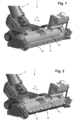
- the nozzle arrangement 1 is equipped with a ramp element 30 as a working member that is configured to assume one of at two possible positions on the nozzle arrangement 1, namely a lowered position as shown in figure 1 , which is an active position of the ramp element 30, and a raised position as shown in figure 2 , which is an inactive position of the ramp element 30.
- the ramp element 30 is arranged at a side of the nozzle arrangement 1 that is a front side in the advancement direction da. At the active position, the ramp element 30 acts to limit air flow from the front side of the nozzle arrangement 1 to the nozzle arrangement 1. In this way, pressure loss which would otherwise occur under the influence of the interaction with a porous soft surface is prevented, so that dirt removal from such a type of surface is not compromised.
- the nozzle arrangement 1 is equipped with a member setting mechanism 40 that is configured to ensure that the position of the ramp element 30 is always appropriate in view of the type of surface 2 to be cleaned.
- the member setting mechanism 40 is particularly configured to automatically set the position of the ramp element 30 under the influence of the forces exerted by the user for moving the nozzle arrangement 1 across the surface 2 during a cleaning action as will now be explained.
- the housing 10 of the nozzle arrangement 1 comprises two portions which are movable relative to each other to some extent, one of those housing portions being associated with the coupling area 11 and the other of those housing portions being associated with the brush area 13.
- the ramp element 30 is coupled to the housing portion associated with the coupling area 11 through a hinging construction 41.
- a resilient element 42 which is a coil spring in the shown example, is arranged between the two housing portions. In a default situation without any force being exerted on the housing portion associated with the coupling area 11, the resilient element 42 acts to push the housing portions apart to such an extent that the hinging construction 41 is in a position for realizing the raised, inactive position of the ramp element 30.
- the characteristics of the resilient element 42 are chosen such that when a pushing force F push is exerted on the portion associated with the coupling area 11, as illustrated in figure 3 , this pushing force F push acts to realize forward movement of the nozzle arrangement 1 on the surface 2 without forcing movement of the ramp element 30 from the inactive position to the active position as long as the value of this pushing force F push is lower than a value of a counterforce exerted by the resilient element 42, and acts to realize forward movement of the nozzle arrangement 1 on the surface 2 while also forcing movement of the ramp element 30 from the inactive position to the active position when the value of this pushing force F push exceeds a value of the counterforce, as indicated in figure 3 by means of a curved arrow.
- the ramp element 30 in the active position is depicted in continuous lines and the ramp element 30 in the inactive position is depicted in dashed lines.
- this pulling force F pull acts to realize backward movement of the nozzle arrangement 1 on the surface 2.
- movement of the ramp element 30 back from the active position to the inactive position takes place under the influence of action of the resilient element 42, as indicated in figure 4 by means of a curved arrow.
- the ramp element 30 in the active position is depicted in dashed lines and the ramp element 30 in the inactive position is depicted in continuous lines.
- the ramp element 30 is continuously kept in the inactive position when the pushing force F push that is exerted on the nozzle arrangement 1 during the forward movement is lower than a counterforce exerted by the resilient element 42.
- the member setting mechanism 40 acts to move the ramp element 30 from the inactive position to the active position.
- the ramp element 30 is automatically lowered during the forward movement and raised during the backward movement.
- an area of friction that is present between the nozzle arrangement 1 and the surface 2 as the nozzle arrangement 1 is moved on the surface 2, i.e. an area in which the motion resistance is of influence, is indicated in figures 3 and 4 , as a box A f delimited by dashed lines.
- the active position of the ramp element 30 is only obtained when the nozzle arrangement 1 is used on a surface 2 of the soft type, and the inactive position of the ramp element 30 is ensured in respect of a surface 2 of the hard type, as desired.
- nozzle arrangement 1 it is possible to add features to the nozzle arrangement 1 to enable locking the position of the ramp element 30. By locking the ramp element 30 in the active position, optimal soft surface performance in backward movement can be ensured because when the ramp element 30 stays down, a higher underpressure can be created in the nozzle arrangement 1.
- Other benefits of having locking features may include prevention of unintentional switching on high friction hard surfaces or when bumping into obstacles, or to ensure proper switching on low friction soft floors.
- the member setting mechanism 40 as illustrated in figures 3 and 4 and described in the foregoing is configured to operate in a purely mechanical fashion. That does not alter the fact that the invention also covers embodiments of the nozzle arrangement 1 in which the member setting mechanism 40 acts on the basis of other principles, including principles involving use of an electric detection and control system.
- a nozzle arrangement 1 In the field of cleaning surfaces, a nozzle arrangement 1 is provided that is configured to be applied in a cleaning device and to be moved forward and backward in an advancement direction da of the nozzle arrangement 1 over a surface 2.
- the nozzle arrangement 1 comprises at least one working member 30 configured to assume one of at least two possible positions on the nozzle arrangement 1, and a member setting mechanism 40 configured to automatically set the position of the at least one working member 30 in relation to a value of at least one discrimination parameter that is influenced by motion resistance between the nozzle arrangement 1 and an actual surface 2. In that way, automatic setting of the position of the at least one working element 30 in relation to the surface type is achieved.
Abstract
In the field of cleaning surfaces, a nozzle arrangement (1) is provided that is configured to be applied in a cleaning device and to be moved forward and backward in an advancement direction (da) of the nozzle arrangement (1) over a surface (2). The nozzle arrangement (1) comprises at least one working member (30) configured to assume one of at least two possible positions on the nozzle arrangement (1), and a member setting mechanism (40) configured to automatically set the position of the at least one working member (30) in relation to a value of at least one discrimination parameter that is influenced by motion resistance between the nozzle arrangement (1) and an actual surface (2). In that way, automatic setting of the position of the at least one working element (30) in relation to the surface type is achieved.
Description
- The invention relates to a nozzle arrangement configured to be applied in a cleaning device and to be used in a cleaning action on a surface, wherein the nozzle arrangement: is configured to be moved forward and backward in an advancement direction of the nozzle arrangement over the surface, comprises at least one working member configured to assume one of at least two possible positions on the nozzle arrangement, and comprises a member setting mechanism configured to automatically set the position of the at least one working member.
- Further, the invention relates to a vacuum cleaner comprising a nozzle arrangement as mentioned, which vacuum cleaner may be a cordless vacuum cleaner and/or a stick vacuum cleaner.
- Vacuum cleaners are known for removing dirt from a surface to be cleaned. The term "dirt" as used in the present text is to be understood so as to cover any contamination as may be present on a surface and that can be removed under the influence of a vacuum cleaning action, probably combined with another cleaning action such as mopping. Practical examples in this respect include dust and small particles of any kind, and also wet types of contamination such as spilled drinks. A practical example of the surface to be cleaned is a floor, wherein the floor may be of any kind, such as a wooden floor, a carpet floor, a tile floor, etc.
- Generally, a vacuum cleaner has a vacuum cleaner head, which is commonly referred to by terms such as suction head, suction nozzle, or nozzle arrangement. In the present text, the latter term will be used. The nozzle arrangement is the part of the vacuum cleaner where the actual process of picking up dirt from a surface to be cleaned is to take place and which is therefore to be put on or at least close to the surface. Further, a vacuum cleaner normally comprises a body portion including a dirt accumulating area and an arrangement configured to act on the nozzle arrangement so that a suction force is prevailing in the nozzle arrangement during operation of the vacuum cleaner. The suction force serves to facilitate transport of dirt that is picked up from the surface during operation of the vacuum cleaner towards the dirt accumulating area. The suction force may also have a function in the actual process of picking up the dirt from the surface. On the other hand, the nozzle arrangement may be equipped with at least one movable component for interacting with the surface in order to pick up the dirt, such as at least one rotatable brush that may serve as an agitator of the dirt and that may particularly be configured to help dislodge dirt from the surface and direct it to further inside the nozzle arrangement.
-
US 3,798,704 discloses a vacuum cleaner nozzle which has a passageway providing a path of flow for air from a suction inlet to an outlet, the suction inlet being defined by an apertured flat surface part which serves as a working member for cleaning rugs/carpets. A brush, which serves as another working member for cleaning hard floors, is mounted on the nozzle at the vicinity of the suction in let for movement between upper and lower positions respectively above and below the suction inlet. Thus, the vacuum cleaner nozzle has a pair of working members, one for cleaning rugs/carpets and the other for cleaning hard floors. The vacuum cleaner nozzle is designed to automatically place the correct working member in cleaning position when the nozzle is moved over a rug/carpet or a hard floor. To that end, the working member for cleaning rugs/carpets is realized as a smooth operating member and the working member for cleaning hard floors is realized as a brush operating member. The smooth operating member automatically functions to perform cleaning when the flow of air in its path of flow between the suction inlet and outlet of the nozzle is at or less than a predetermined speed, and the brush operating member automatically functions to perform cleaning when the flow of air exceeds the predetermined speed. This is particularly accomplished by providing structures such as scoops or funnels, which are in the direct path of movement of at least a part of the air flowing between the suction inlet and outlet when such flow of air exceeds the predetermined speed, the air striking such structure being diverted by the latter into a second passageway to produce a dynamic pressure component of air to promote movement of the brush operating member to its working position. - In general, it is known to have at least one working member in a nozzle arrangement. For example, a type of working member is known which is especially configured to interact with a soft floor such as a carpet floor, and which should not be allowed to contact a hard floor in order to avoid damage to the hard floor in the form of scratches, for example. Nozzle arrangements are known which are configured to enable manual setting of the position of the working member, in which case appropriate action by a user is required, depending on the type of the surface to be cleaned. There is a risk that the user forgets to switch the position of the working member when another type of surface is to be cleaned, or that the user is confused about which position of the working member should go with which position of the working member and sets an incorrect position of the working member for that reason. Further, nozzle arrangements are known in which the underpressure prevailing in the nozzle arrangement when the nozzle arrangement is used on a hard floor is used to lift the working member off the floor. In the context of the latter nozzle arrangements, the problems involved in dependency on user action are alleviated, but the fact is that relying on underpressure effects is not possible/suitable in all possible situations. For example, in a case of cordless stick vacuum cleaners, the level of underpressure is insufficient to realize the desired setting of the working member. Also, the constructions enabling use of underpressure to bring about movement of the working member require a lot of space in the nozzle arrangements and thereby significantly add to bulkiness of the nozzle arrangements.
- It is an object of the invention to provide a way of setting a position of at least one working member of a nozzle arrangement that does not require user action, that does not involve use of bulky mechanics and/or complex/expensive electronics, and that does not require high levels of underpressure.
- In view of the foregoing, the invention provides a nozzle arrangement configured to be applied in a cleaning device and to be used in a cleaning action on a surface, wherein the nozzle arrangement: is configured to be moved forward and backward in an advancement direction of the nozzle arrangement over the surface, comprises at least one working member configured to assume one of at least two possible positions on the nozzle arrangement, and comprises a member setting mechanism configured to automatically set the position of the at least one working member in relation to a value of at least one discrimination parameter that is influenced by motion resistance between the nozzle arrangement and an actual surface.
- It follows from the foregoing definition of the nozzle arrangement according to the invention that the member setting mechanism functions on the basis of another principle than using underpressure for determining the position of the at least one working member. In the context of the invention, it is found that it is possible to operate the member setting mechanism in dependency on motion resistance between the nozzle arrangement and an actual surface, using to advantage the insight that generally speaking, the motion resistance is significantly lower when the surface to be cleaned is a hard floor than when the surface is a soft floor. This allows for embodiments of the nozzle arrangement in which the value of the at least one discrimination parameter is found through active detection, or even embodiments of the nozzle arrangement in which the member setting mechanism is designed such that changes in motion resistance between the nozzle arrangement and the surface act on the member setting mechanism in a direct mechanical fashion, such a through transfer of force.
- The invention covers various types of working member. In this respect, it is noted that it may be practical if the at least one working member is configured to assume at least one active position at which the at least one working member is capable of influencing interaction between the nozzle arrangement and the surface, and an inactive position, i.e. a position at which the at least one working member is not capable of doing so. It may be so that the at least one working member is in a position for contacting the surface when the at least one working member is in the at least one active position, although this is not essential in the context of the invention. In any case, it may be practical if the member setting mechanism is configured to put the at least one working member from the inactive position to an active position when the value of the at least one discrimination parameter exceeds a reference value. In particular, such a reference value may be between a value of the at least one discrimination parameter related to movement of the nozzle arrangement over a hard surface and a value of the at least one discrimination parameter related to movement of the nozzle arrangement over a soft surface providing higher motion resistance than the hard surface. This option is interesting to a practical case of the at least one working member being intended to only interact with a soft surface and not with a hard surface.
- In the context of the invention, various options exist in respect of the at least one discrimination parameter that is influenced by motion resistance between the nozzle arrangement and the surface to be cleaned. According to a first option, the nozzle arrangement is configured to be moved forward and backward in the advancement direction of the nozzle arrangement over the surface under the influence of an external pushing force and an external pulling force, respectively, and the at least one discrimination parameter is a parameter representative of the external pushing force. The external pushing force and the external pulling force may particularly be exerted by a user. According to an alternative or an additional option, the nozzle arrangement comprises at least one rotatable brush configured to interact with the surface, and a motor configured to drive the brush, and the at least one discrimination parameter is a parameter representative of power consumption of the motor. The first option is practical in view of the assumption that an increase of external pushing force is indicative of an increase of motion resistance between the nozzle arrangement and the surface, whereas the latter option is practical in view of the assumption that an increase of power consumption of the motor is indicative of an increase of the motion resistance. In general, higher force is needed to push the nozzle arrangement across the surface to be cleaned when the structure of the surface changes to a structure involving increased motion resistance. Similarly, more power is needed to maintain rotation of the brush when the structure of the surface changes to a structure involving increased motion resistance. Putting both options to practice in addition to each other may contribute to accuracy and/or speed of the reaction of the member setting mechanism to a change of surface type.
- An embodiment of the nozzle arrangement is feasible in which the member setting mechanism comprises a sensor system including a sensor configured to generate output that is representative of the value of the at least one discrimination parameter and a controller configured to receive the sensor's output and to apply an algorithm designed to determine the position of the at least one working member to be set on the basis of the sensor's output. For example, if the at least one discrimination parameter is a parameter representative of the external pushing force as suggested in the foregoing, it may be so that the sensor is a force sensor arranged at an appropriate position in/on the nozzle arrangement. Generally speaking, the invention covers electronic control of the position of the at least one working member.
- Also, an embodiment of the nozzle arrangement is feasible in which the member setting system comprises a mechanical system including a reaction element configured to provide a counterforce acting against the external pushing force. In this way, it is possible to have pure mechanical control of the position of the at least one working member. A practical example of the reaction element is a resilient element such as a spring element. In the case that the working member is configured to assume the at least one active position and the inactive position mentioned earlier, it may practical if the reaction element is configured to enable the at least one working member to remain in the inactive position as long as the value of the external pushing force is lower than a value of the counterforce and to enable the at least one working member to move from the inactive position to an active position when the value of the external pushing force exceeds the value of the counterforce. This is again appropriate in the situation in which it is desired to have the at least one working element in the inactive position if the nozzle arrangement is on a hard surface. It may further be so that the reaction element is configured to enable the at least one working member to move from the active position to the inactive position when the value of the external pushing force drops below the value of the counterforce. In that way, a fully automated link between the position of the at least one working member and the type of surface is realized, wherein the at least one working member is automatically put to an active position when the nozzle arrangement is used on a soft surface, and wherein the at least one working member is automatically put to the inactive position when the nozzle arrangement is used on a hard surface.
- It may be practical if the nozzle arrangement is equipped with a locking mechanism configured to assume one of a position to lock the at least one working member in place and a position to release the at least one working member, because in that case, a practical possibility of avoiding unintentional switching of the position of the at least one working member is realized. In general, having a locking mechanism offers a functionality in securing the position of the at least one working member, independent from external factors. Such a locking mechanism may be controlled in any suitable manner, in a manual and/or automated fashion.
- As suggested earlier, the at least one working member may be of any appropriate type. In a practical embodiment of the nozzle arrangement according to the invention, the at least one working member comprises a ramp element arranged at a side of the nozzle arrangement that is a front side in the advancement direction, wherein the ramp element is movable between an active position at which the ramp element acts to limit air flow from the front side of the nozzle arrangement to the nozzle arrangement, and an inactive position. It is typically intended to set the active position of the ramp element when the nozzle arrangement is used on a soft surface, in order to ensure sufficient air flow from the surface to the nozzle arrangement by delimiting an appropriate area and thereby providing compensation for the porous nature of the soft surface, and to set the inactive position of the ramp element when the nozzle arrangement is used on a hard surface.
- The nozzle arrangement may particularly be configured to be applied in a cleaning device including an air suction source i.e., a vacuum cleaner, and it is practical if the nozzle arrangement comprises a housing that includes a coupling area configured to enable coupling of the housing to the air suction source of the cleaning device.
- The invention further relates to a vacuum cleaner comprising a nozzle arrangement as mentioned, which vacuum cleaner may be a cordless vacuum cleaner and/or a stick vacuum cleaner. As is known per se in the relevant field, a vacuum cleaner is an appliance comprising a body portion to which the nozzle arrangement is connectable, wherein the body portion includes a dirt accumulating area and an arrangement configured to act on the nozzle arrangement so that a suction force is prevailing in the nozzle arrangement during operation of the vacuum cleaner.
- The above-described and other aspects of the invention will be apparent from and elucidated with reference to the following detailed description of a practical embodiment of the nozzle arrangement as defined and described in the foregoing.
- The invention will now be explained in greater detail with reference to the figures, in which equal or similar parts are indicated by the same reference signs, and in which:
-
Figure 1 diagrammatically shows a perspective view of a nozzle arrangement according to an embodiment of the invention including a ramp element that is movably arranged on the nozzle arrangement, with cover parts of the nozzle arrangement removed and the ramp element shown in an active position, -
Figure 2 diagrammatically shows a similar view of the nozzle arrangement, with the ramp element shown in an inactive position, -
Figures 3 is a schematic depiction of a number of components of the nozzle arrangement and illustrates movement of the ramp element from the inactive position to the active position, and -
Figure 4 is a similar depiction of the same components of the nozzle arrangement and illustrates movement of the ramp element from the active position to the inactive position. -
Figures 1-4 relate to anozzle arrangement 1 according to an embodiment of the invention. It is to be noted that the embodiment shown and illustrated in the figures is a practical one out of various possibilities covered by the invention, and that aspects of the embodiment as will be discussed in the following are in no way to be understood so as to be limiting to the invention as defined in the attached claims. - The
nozzle arrangement 1 is configured to be applied in a cleaning device including an air suction source (not shown) and comprises ahousing 10 that includes acoupling area 11 configured to enable coupling of thehousing 10 to the air suction source of the cleaning device. At the side at which thehousing 10 is to face asurface 2 to be cleaned, thehousing 10 is provided with anopening 12, as can be seen infigures 3 and 4 . Further, thenozzle arrangement 1 comprises arotatable brush 20 configured to interact with thesurface 2 and arranged in abrush area 13 of thehousing 10. Thebrush 20 may be of any suitable type, such as the type comprising acore 21 andbrush elements 22 extending from thecore 21, wherein free end portions of thebrush elements 22 are configured to contact thesurface 2 and to thereby agitate dirt as may be present on thesurface 2. When thenozzle arrangement 1 is installed as part of the cleaning device, indeed, and the cleaning device is operated to clean thesurface 2, thebrush 20 is driven so as to rotate, and the air suction source is in an active state. As a result, dirt as may be present on thesurface 2 is removed from thesurface 2 and displaced to inside thehousing 10 of thenozzle arrangement 1. The dirt is made to move further downstream in thehousing 10, from thebrush area 13 towards thecoupling area 11, wherein the dirt passes aninternal opening 14 of thehousing 10. - In the context of the invention, embodiments of the
nozzle arrangement 1 which are configured for autonomous movement are feasible. In the shown example, thenozzle arrangement 1 is configured to be moved forward and backward in an advancement direction da of thenozzle arrangement 1 over thesurface 2 under the influence of user action, particularly under the influence of a pushing force and a pulling force, respectively, exerted by a user. Infigures 3 and 4 , a forward and backward movement, respectively, are indicated by means of a horizontal arrow. For the purpose of performing a cleaning action, the user takes hold of an appropriate portion of the cleaning device to which thenozzle arrangement 1 is coupled, which may be a handle on a body portion of the cleaning device in case the cleaning device is a stick vacuum cleaner or a grip portion on a hose of the cleaning device in case the cleaning device is a canister vacuum cleaner, and manipulates this portion so that the movement of thenozzle arrangement 1 on thesurface 2 as desired is realized. - The
nozzle arrangement 1 is equipped with aramp element 30 as a working member that is configured to assume one of at two possible positions on thenozzle arrangement 1, namely a lowered position as shown infigure 1 , which is an active position of theramp element 30, and a raised position as shown infigure 2 , which is an inactive position of theramp element 30. Theramp element 30 is arranged at a side of thenozzle arrangement 1 that is a front side in the advancement direction da. At the active position, theramp element 30 acts to limit air flow from the front side of thenozzle arrangement 1 to thenozzle arrangement 1. In this way, pressure loss which would otherwise occur under the influence of the interaction with a porous soft surface is prevented, so that dirt removal from such a type of surface is not compromised. - The fact is that the
ramp element 30 is only to be put to the active position when thesurface 2 to be cleaned is a soft surface, while theramp element 30 is to be put to the inactive position when thesurface 2 to be cleaned is a hard surface in order to avoid damage to that type of surface. For the purpose of setting the position of theramp element 30, thenozzle arrangement 1 is equipped with amember setting mechanism 40 that is configured to ensure that the position of theramp element 30 is always appropriate in view of the type ofsurface 2 to be cleaned. In the context of the present embodiment of thenozzle arrangement 1, themember setting mechanism 40 is particularly configured to automatically set the position of theramp element 30 under the influence of the forces exerted by the user for moving thenozzle arrangement 1 across thesurface 2 during a cleaning action as will now be explained. - The
housing 10 of thenozzle arrangement 1 comprises two portions which are movable relative to each other to some extent, one of those housing portions being associated with thecoupling area 11 and the other of those housing portions being associated with thebrush area 13. Theramp element 30 is coupled to the housing portion associated with thecoupling area 11 through a hingingconstruction 41. Further, aresilient element 42, which is a coil spring in the shown example, is arranged between the two housing portions. In a default situation without any force being exerted on the housing portion associated with thecoupling area 11, theresilient element 42 acts to push the housing portions apart to such an extent that the hingingconstruction 41 is in a position for realizing the raised, inactive position of theramp element 30. The characteristics of theresilient element 42 are chosen such that when a pushing force Fpush is exerted on the portion associated with thecoupling area 11, as illustrated infigure 3 , this pushing force Fpush acts to realize forward movement of thenozzle arrangement 1 on thesurface 2 without forcing movement of theramp element 30 from the inactive position to the active position as long as the value of this pushing force Fpush is lower than a value of a counterforce exerted by theresilient element 42, and acts to realize forward movement of thenozzle arrangement 1 on thesurface 2 while also forcing movement of theramp element 30 from the inactive position to the active position when the value of this pushing force Fpush exceeds a value of the counterforce, as indicated infigure 3 by means of a curved arrow. Infigure 3 , theramp element 30 in the active position is depicted in continuous lines and theramp element 30 in the inactive position is depicted in dashed lines. When subsequently a pulling force Fpull is exerted on the portion associated with thecoupling area 11, as illustrated infigure 4 , this pulling force Fpull acts to realize backward movement of thenozzle arrangement 1 on thesurface 2. In the process, movement of theramp element 30 back from the active position to the inactive position takes place under the influence of action of theresilient element 42, as indicated infigure 4 by means of a curved arrow. Infigure 4 , theramp element 30 in the active position is depicted in dashed lines and theramp element 30 in the inactive position is depicted in continuous lines. - It follows from the foregoing that when the
nozzle arrangement 1 is moved forward and backward in the advancement direction da of thenozzle arrangement 1 over thesurface 2, theramp element 30 is continuously kept in the inactive position when the pushing force Fpush that is exerted on thenozzle arrangement 1 during the forward movement is lower than a counterforce exerted by theresilient element 42. However, when the pushing force Fpush that is exerted on thenozzle arrangement 1 during the forward movement exceeds the counterforce, themember setting mechanism 40 acts to move theramp element 30 from the inactive position to the active position. Thus, when thenozzle arrangement 1 is used to perform a cleaning action on asurface 2 involving motion resistance between thenozzle arrangement 1 and thesurface 2 that is so high that a value of the pushing force Fpush needed to move thenozzle arrangement 1 forward is higher than the value of the counterforce of theresilient element 42, theramp element 30 is automatically lowered during the forward movement and raised during the backward movement. - For illustration purposes, an area of friction that is present between the
nozzle arrangement 1 and thesurface 2 as thenozzle arrangement 1 is moved on thesurface 2, i.e. an area in which the motion resistance is of influence, is indicated infigures 3 and 4 , as a box Af delimited by dashed lines. In view of the fact that in general, a relatively high motion resistance is associated with asurface 2 of the soft type and a relatively low motion resistance is associated with asurface 2 of the hard type, the active position of theramp element 30 is only obtained when thenozzle arrangement 1 is used on asurface 2 of the soft type, and the inactive position of theramp element 30 is ensured in respect of asurface 2 of the hard type, as desired. - Additionally, it is possible to add features to the
nozzle arrangement 1 to enable locking the position of theramp element 30. By locking theramp element 30 in the active position, optimal soft surface performance in backward movement can be ensured because when theramp element 30 stays down, a higher underpressure can be created in thenozzle arrangement 1. Other benefits of having locking features may include prevention of unintentional switching on high friction hard surfaces or when bumping into obstacles, or to ensure proper switching on low friction soft floors. - The
member setting mechanism 40 as illustrated infigures 3 and 4 and described in the foregoing is configured to operate in a purely mechanical fashion. That does not alter the fact that the invention also covers embodiments of thenozzle arrangement 1 in which themember setting mechanism 40 acts on the basis of other principles, including principles involving use of an electric detection and control system. - It will be clear to a person skilled in the art that the scope of the invention is not limited to the examples discussed in the foregoing, but that several amendments and modifications thereof are possible without deviating from the scope of the invention as defined in the attached claims. It is intended that the invention be construed as including all such amendments and modifications insofar they come within the scope of the claims or the equivalents thereof. While the invention has been illustrated and described in detail in the figures and the description, such illustration and description are to be considered illustrative or exemplary only, and not restrictive. The invention is not limited to the disclosed embodiments. The drawings are schematic, wherein details which are not required for understanding the invention may have been omitted, and not necessarily to scale.
- Variations to the disclosed embodiments can be understood and effected by a person skilled in the art in practicing the claimed invention, from a study of the figures, the description and the attached claims. In the claims, the word "comprising" does not exclude other steps or elements, and the indefinite article "a" or "an" does not exclude a plurality. Any reference signs in the claims should not be construed as limiting the scope of the invention.
- Elements and aspects discussed for or in relation with a particular embodiment may be suitably combined with elements and aspects of other embodiments, unless explicitly stated otherwise. Thus, the mere fact that certain measures are recited in mutually different dependent claims does not indicate that a combination of these measures cannot be used to advantage.
- The terms "comprise" and "include" as used in this text will be understood by a person skilled in the art as covering the term "consist of'. Hence, the term "comprise" or "include" may in respect of an embodiment mean "consist of', but may in another embodiment mean "contain/have/be equipped with at least the defined species and optionally one or more other species".
- Notable aspects of the invention are summarized as follows. In the field of cleaning surfaces, a
nozzle arrangement 1 is provided that is configured to be applied in a cleaning device and to be moved forward and backward in an advancement direction da of thenozzle arrangement 1 over asurface 2. Thenozzle arrangement 1 comprises at least one workingmember 30 configured to assume one of at least two possible positions on thenozzle arrangement 1, and amember setting mechanism 40 configured to automatically set the position of the at least one workingmember 30 in relation to a value of at least one discrimination parameter that is influenced by motion resistance between thenozzle arrangement 1 and anactual surface 2. In that way, automatic setting of the position of the at least one workingelement 30 in relation to the surface type is achieved.
Claims (15)
- Nozzle arrangement (1) configured to be applied in a cleaning device and to be used in a cleaning action on a surface (2), wherein the nozzle arrangement (1):- is configured to be moved forward and backward in an advancement direction (da) of the nozzle arrangement (1) over the surface (2),- comprises at least one working member (30) configured to assume one of at least two possible positions on the nozzle arrangement (1), and- comprises a member setting mechanism (40) configured to automatically set the position of the at least one working member (30) in relation to a value of at least one discrimination parameter that is influenced by motion resistance between the nozzle arrangement (1) and an actual surface (2).
- Nozzle arrangement (1) according to claim 1, wherein the at least one working member (30) is configured to assume at least one active position at which the at least one working member (30) is capable of influencing interaction between the nozzle arrangement (1) and the surface (2), and an inactive position.
- Nozzle arrangement (1) according to claim 2, wherein the member setting mechanism (40) is configured to put the at least one working member (30) from the inactive position to an active position when the value of the at least one discrimination parameter exceeds a reference value.
- Nozzle arrangement (1) according to claim 3, wherein the reference value is between a value of the at least one discrimination parameter related to movement of the nozzle arrangement (1) over a hard surface (2) and a value of the at least one discrimination parameter related to movement of the nozzle arrangement (1) over a soft surface (2) providing higher motion resistance than the hard surface (2).
- Nozzle arrangement (1) according to any of claims 1-4, wherein the nozzle arrangement (1) is configured to be moved forward and backward in the advancement direction (da) of the nozzle arrangement (1) over the surface (2) under the influence of an external pushing force (Fpush) and an external pulling force (Fpull), respectively, and wherein the at least one discrimination parameter is a parameter representative of the external pushing force (Fpush).
- Nozzle arrangement (1) according to any of claims 1-5, comprising at least one rotatable brush (20) configured to interact with the surface (2), and a motor configured to drive the brush (20), wherein the at least one discrimination parameter is a parameter representative of power consumption of the motor.
- Nozzle arrangement (1) according to any of claims 1-6, wherein the member setting mechanism (40) comprises a sensor system including a sensor configured to generate output that is representative of the value of the at least one discrimination parameter and a controller configured to receive the sensor's output and to apply an algorithm designed to determine the position of the at least one working member (30) to be set on the basis of the sensor's output.
- Nozzle arrangement (1) according to claim 5, wherein the member setting system (40) comprises a mechanical system including a reaction element (42) configured to provide a counterforce acting against the external pushing force (Fpush).
- Nozzle arrangement (1) according to claim 8, comprising the working member (30) as defined in claim 2, wherein the reaction element (42) is configured to enable the at least one working member (30) to remain in the inactive position as long as the value of the external pushing force (Fpush) is lower than a value of the counterforce and to enable the at least one working member (30) to move from the inactive position to an active position when the value of the external pushing force (Fpush) exceeds the value of the counterforce.
- Nozzle arrangement (1) according to claim 9, wherein the reaction element (42) is configured to enable the at least one working member (30) to move from the active position to the inactive position when the value of the external pushing force (Fpush) drops below the value of the counterforce.
- Nozzle arrangement (1) according to any of claims 8-10, wherein the reaction element (42) comprises at least one resilient element.
- Nozzle arrangement (1) according to any of claims 1-11, comprising a locking mechanism configured to assume one of a position to lock the at least one working member (30) in place and a position to release the at least one working member (30).
- Nozzle arrangement (1) according to any of claims 1-12, wherein the at least one working member (30) comprises a ramp element arranged at a side of the nozzle arrangement (1) that is a front side in the advancement direction (da), and wherein the ramp element (30) is movable between an active position at which the ramp element (30) acts to limit air flow from the front side of the nozzle arrangement (1) to the nozzle arrangement (1), and an inactive position.
- Nozzle arrangement (1) according to any of claims 1-13, configured to be applied in a cleaning device including an air suction source, and comprising a housing (10) that includes a coupling area (11) configured to enable coupling of the housing (10) to the air suction source of the cleaning device.
- Vacuum cleaner, comprising a nozzle arrangement (1) according to any of claims 1-14.
Priority Applications (2)
| Application Number | Priority Date | Filing Date | Title |
|---|---|---|---|
| EP21194418.6A EP4144272A1 (en) | 2021-09-01 | 2021-09-01 | Setting a position of at least one working member in a nozzle arrangement |
| PCT/EP2022/073844 WO2023031059A1 (en) | 2021-09-01 | 2022-08-26 | Setting a position of at least one working member in a nozzle arrangement |
Applications Claiming Priority (1)
| Application Number | Priority Date | Filing Date | Title |
|---|---|---|---|
| EP21194418.6A EP4144272A1 (en) | 2021-09-01 | 2021-09-01 | Setting a position of at least one working member in a nozzle arrangement |
Publications (1)
| Publication Number | Publication Date |
|---|---|
| EP4144272A1 true EP4144272A1 (en) | 2023-03-08 |
Family
ID=77595478
Family Applications (1)
| Application Number | Title | Priority Date | Filing Date |
|---|---|---|---|
| EP21194418.6A Withdrawn EP4144272A1 (en) | 2021-09-01 | 2021-09-01 | Setting a position of at least one working member in a nozzle arrangement |
Country Status (2)
| Country | Link |
|---|---|
| EP (1) | EP4144272A1 (en) |
| WO (1) | WO2023031059A1 (en) |
Citations (3)
| Publication number | Priority date | Publication date | Assignee | Title |
|---|---|---|---|---|
| US3798704A (en) | 1971-02-26 | 1974-03-26 | Electrolux Ab | Self-acting combination rug and floor vacuum cleaner nozzle |
| US4447931A (en) * | 1980-12-03 | 1984-05-15 | Aktiebolaget Electrolux | Remotely controlled vacuum cleaner nozzle |
| WO2013027140A1 (en) * | 2011-08-23 | 2013-02-28 | Koninklijke Philips Electronics N.V. | Cleaning device for cleaning a surface comprising a brush and a squeegee element |
-
2021
- 2021-09-01 EP EP21194418.6A patent/EP4144272A1/en not_active Withdrawn
-
2022
- 2022-08-26 WO PCT/EP2022/073844 patent/WO2023031059A1/en active Application Filing
Patent Citations (3)
| Publication number | Priority date | Publication date | Assignee | Title |
|---|---|---|---|---|
| US3798704A (en) | 1971-02-26 | 1974-03-26 | Electrolux Ab | Self-acting combination rug and floor vacuum cleaner nozzle |
| US4447931A (en) * | 1980-12-03 | 1984-05-15 | Aktiebolaget Electrolux | Remotely controlled vacuum cleaner nozzle |
| WO2013027140A1 (en) * | 2011-08-23 | 2013-02-28 | Koninklijke Philips Electronics N.V. | Cleaning device for cleaning a surface comprising a brush and a squeegee element |
Also Published As
| Publication number | Publication date |
|---|---|
| WO2023031059A1 (en) | 2023-03-09 |
Similar Documents
| Publication | Publication Date | Title |
|---|---|---|
| US11672388B2 (en) | Hand-held surface cleaning device | |
| EP2117402B1 (en) | Wet/dry floor cleaning device | |
| US5467502A (en) | Height adjusting system for upright vacuum cleaner | |
| KR101491002B1 (en) | Vacuum cleaner | |
| EP1795105B1 (en) | Vacuum cleaner | |
| US8720004B2 (en) | Floor tool | |
| US4766638A (en) | Four-way vacuum cleaner | |
| CA2413401C (en) | Convertible vacuum cleaner | |
| EP3209176B1 (en) | Vacuum cleaner having a conversion valve | |
| US8060980B2 (en) | Floor care appliance equipped with break-over protected latch assembly | |
| KR101487787B1 (en) | A suction brush for vacuum cleaner | |
| EP1364608A2 (en) | Vaccum cleaner and suction nozzle employed therein | |
| EP1782724A2 (en) | Cleaning apparatus with removable handle with electronic user interface | |
| WO2016054538A1 (en) | Vacuum cleaner including a removable dirt collection assembly | |
| EP4144272A1 (en) | Setting a position of at least one working member in a nozzle arrangement | |
| KR20060019739A (en) | A structure of suction nozzle in vacuum cleaner | |
| CN117915816A (en) | Setting the position of at least one working member in a suction nozzle device | |
| US11786090B2 (en) | Floor nozzle for a vacuum cleaner and vacuum cleaner | |
| KR101208559B1 (en) | An upright type vacuum cleaner | |
| CN217659639U (en) | Mop device and floor cleaning machine | |
| US10980381B1 (en) | Nozzle assembly for vacuum device | |
| EP2636349A1 (en) | Suction device for electric cleaner and electric cleaner using same | |
| EP2409618B1 (en) | Vacuum cleaner | |
| JP2001061720A (en) | Vacuum cleaner | |
| AU709565B2 (en) | Vacuum cleaner |
Legal Events
| Date | Code | Title | Description |
|---|---|---|---|
| PUAI | Public reference made under article 153(3) epc to a published international application that has entered the european phase |
Free format text: ORIGINAL CODE: 0009012 |
|
| STAA | Information on the status of an ep patent application or granted ep patent |
Free format text: STATUS: THE APPLICATION HAS BEEN PUBLISHED |
|
| AK | Designated contracting states |
Kind code of ref document: A1 Designated state(s): AL AT BE BG CH CY CZ DE DK EE ES FI FR GB GR HR HU IE IS IT LI LT LU LV MC MK MT NL NO PL PT RO RS SE SI SK SM TR |
|
| RAP3 | Party data changed (applicant data changed or rights of an application transferred) |
Owner name: VERSUNI HOLDING B.V. |
|
| STAA | Information on the status of an ep patent application or granted ep patent |
Free format text: STATUS: THE APPLICATION IS DEEMED TO BE WITHDRAWN |
|
| 18D | Application deemed to be withdrawn |
Effective date: 20230909 |