EP4144201B1 - Steuerung des streumusters von rückständen durch kontinuierliche änderung der verteilungsfrequenz - Google Patents
Steuerung des streumusters von rückständen durch kontinuierliche änderung der verteilungsfrequenz Download PDFInfo
- Publication number
- EP4144201B1 EP4144201B1 EP22193778.2A EP22193778A EP4144201B1 EP 4144201 B1 EP4144201 B1 EP 4144201B1 EP 22193778 A EP22193778 A EP 22193778A EP 4144201 B1 EP4144201 B1 EP 4144201B1
- Authority
- EP
- European Patent Office
- Prior art keywords
- residue
- combine
- angle
- spreader wheel
- controller
- Prior art date
- Legal status (The legal status is an assumption and is not a legal conclusion. Google has not performed a legal analysis and makes no representation as to the accuracy of the status listed.)
- Active
Links
Images


Classifications
-
- A—HUMAN NECESSITIES
- A01—AGRICULTURE; FORESTRY; ANIMAL HUSBANDRY; HUNTING; TRAPPING; FISHING
- A01D—HARVESTING; MOWING
- A01D41/00—Combines, i.e. harvesters or mowers combined with threshing devices
- A01D41/12—Details of combines
- A01D41/1243—Devices for laying-out or distributing the straw
-
- A—HUMAN NECESSITIES
- A01—AGRICULTURE; FORESTRY; ANIMAL HUSBANDRY; HUNTING; TRAPPING; FISHING
- A01F—PROCESSING OF HARVESTED PRODUCE; HAY OR STRAW PRESSES; DEVICES FOR STORING AGRICULTURAL OR HORTICULTURAL PRODUCE
- A01F12/00—Parts or details of threshing apparatus
- A01F12/44—Grain cleaners; Grain separators
- A01F12/442—Rotary cleaners
-
- A—HUMAN NECESSITIES
- A01—AGRICULTURE; FORESTRY; ANIMAL HUSBANDRY; HUNTING; TRAPPING; FISHING
- A01D—HARVESTING; MOWING
- A01D41/00—Combines, i.e. harvesters or mowers combined with threshing devices
- A01D41/12—Details of combines
- A01D41/127—Control or measuring arrangements specially adapted for combines
- A01D41/1274—Control or measuring arrangements specially adapted for combines for drives
-
- A—HUMAN NECESSITIES
- A01—AGRICULTURE; FORESTRY; ANIMAL HUSBANDRY; HUNTING; TRAPPING; FISHING
- A01D—HARVESTING; MOWING
- A01D41/00—Combines, i.e. harvesters or mowers combined with threshing devices
- A01D41/12—Details of combines
- A01D41/127—Control or measuring arrangements specially adapted for combines
- A01D41/1276—Control or measuring arrangements specially adapted for combines for cleaning mechanisms
-
- A—HUMAN NECESSITIES
- A01—AGRICULTURE; FORESTRY; ANIMAL HUSBANDRY; HUNTING; TRAPPING; FISHING
- A01F—PROCESSING OF HARVESTED PRODUCE; HAY OR STRAW PRESSES; DEVICES FOR STORING AGRICULTURAL OR HORTICULTURAL PRODUCE
- A01F12/00—Parts or details of threshing apparatus
- A01F12/18—Threshing devices
- A01F12/181—Adjustable threshing mechanisms
-
- A—HUMAN NECESSITIES
- A01—AGRICULTURE; FORESTRY; ANIMAL HUSBANDRY; HUNTING; TRAPPING; FISHING
- A01F—PROCESSING OF HARVESTED PRODUCE; HAY OR STRAW PRESSES; DEVICES FOR STORING AGRICULTURAL OR HORTICULTURAL PRODUCE
- A01F12/00—Parts or details of threshing apparatus
- A01F12/18—Threshing devices
- A01F12/184—Cleaning means
-
- A—HUMAN NECESSITIES
- A01—AGRICULTURE; FORESTRY; ANIMAL HUSBANDRY; HUNTING; TRAPPING; FISHING
- A01F—PROCESSING OF HARVESTED PRODUCE; HAY OR STRAW PRESSES; DEVICES FOR STORING AGRICULTURAL OR HORTICULTURAL PRODUCE
- A01F12/00—Parts or details of threshing apparatus
- A01F12/58—Control devices; Brakes; Bearings
-
- A—HUMAN NECESSITIES
- A01—AGRICULTURE; FORESTRY; ANIMAL HUSBANDRY; HUNTING; TRAPPING; FISHING
- A01B—SOIL WORKING IN AGRICULTURE OR FORESTRY; PARTS, DETAILS, OR ACCESSORIES OF AGRICULTURAL MACHINES OR IMPLEMENTS, IN GENERAL
- A01B13/00—Ploughs or like machines for special purposes ; Ditch diggers, trench ploughs, forestry ploughs, ploughs for land or marsh reclamation
- A01B13/08—Ploughs or like machines for special purposes ; Ditch diggers, trench ploughs, forestry ploughs, ploughs for land or marsh reclamation for working subsoil
- A01B13/10—Special implements for lifting subsoil layers
- A01B13/12—Means for distributing the layers on the surface
-
- A—HUMAN NECESSITIES
- A01—AGRICULTURE; FORESTRY; ANIMAL HUSBANDRY; HUNTING; TRAPPING; FISHING
- A01D—HARVESTING; MOWING
- A01D87/00—Loaders for hay or like field crops
-
- A—HUMAN NECESSITIES
- A01—AGRICULTURE; FORESTRY; ANIMAL HUSBANDRY; HUNTING; TRAPPING; FISHING
- A01D—HARVESTING; MOWING
- A01D87/00—Loaders for hay or like field crops
- A01D87/0046—Distributing devices at the delivery side of loaders
-
- A—HUMAN NECESSITIES
- A01—AGRICULTURE; FORESTRY; ANIMAL HUSBANDRY; HUNTING; TRAPPING; FISHING
- A01F—PROCESSING OF HARVESTED PRODUCE; HAY OR STRAW PRESSES; DEVICES FOR STORING AGRICULTURAL OR HORTICULTURAL PRODUCE
- A01F25/00—Storing agricultural or horticultural produce; Hanging-up harvested fruit
- A01F25/16—Arrangements in forage silos
- A01F25/18—Loading or distributing arrangements
-
- A—HUMAN NECESSITIES
- A01—AGRICULTURE; FORESTRY; ANIMAL HUSBANDRY; HUNTING; TRAPPING; FISHING
- A01F—PROCESSING OF HARVESTED PRODUCE; HAY OR STRAW PRESSES; DEVICES FOR STORING AGRICULTURAL OR HORTICULTURAL PRODUCE
- A01F29/00—Cutting apparatus specially adapted for cutting hay, straw or the like
- A01F29/09—Details
- A01F29/12—Discharge means
Definitions
- the invention relates to residue spreading pattern system and method for implementation in a harvester combine.
- Combine harvesters implement various functions of crop gathering, threshing, separating, conveying and spreading residue back to the field.
- the US patent applications published as US 2021/0127573 A1 and US 2017/0086372 A1 describe combine harvesters with residue spreaders that may be controlled to affect the distribution of the crop residue onto the soil or field.
- Many existing combines, however, are susceptible to non-uniform residue spread patterns.
- An embodiment includes a combine having a feeder housing for receiving harvested crop, a separating system for threshing the harvested crop to separate grain from residue, a residue spreader wheel spinning for expelling the residue from the combine, and a controller that controls the combine.
- the controller is configured to control the residue spreader wheel to continuously oscillate between a first speed less than a nominal speed and a second speed greater than the nominal speed while spreading the residue.
- Another embodiment includes a combine having a feeder housing for receiving harvested crop, a separating system for threshing the harvested crop to separate grain from residue, a residue spreader wheel spinning and having paddles extending at an angle for expelling the residue from the combine, and a controller that controls the combine.
- the controller is configured to control the paddles of residue spreader wheel to continuously oscillate between a first angle less than a nominal angle and a second angle greater than the nominal angle while spreading the residue.
- aspects of the disclosure provide methods and systems for controlling spreader wheel rotational speed and/or spreader wheel paddle angles to achieve a uniform residue spread pattern.
- an agricultural harvester in the form of a combine 10 (e.g. longitudinal rotary combine), which generally includes a chassis 12, ground engaging wheels 14 and 16, a header 18, a feeder housing 20, an operator cab 22, a threshing and separating system 24, a cleaning system 26, a grain tank 28, and an unloading auger 30.
- a combine 10 e.g. longitudinal rotary combine
- Front wheels 14 are larger flotation type wheels, and rear wheels 16 are smaller steerable wheels. Motive force is selectively applied to front wheels 14 through a power plant in the form of a diesel engine 32 and a transmission (not shown).
- combine 10 is shown as including wheels, is also to be understood that combine 10 may include tracks, such as full tracks or half-tracks.
- Header 18 is mounted to the front of combine 10 and includes a cutter bar 34 for severing crops from a field during forward motion of combine 10.
- a rotatable reel 36 feeds the crop into header 18, and a double auger 38 feeds the severed crop laterally inwardly from each side toward feeder housing 20.
- Feeder housing 20 conveys the cut crop to threshing and separating system 24, and is selectively vertically movable using appropriate actuators, such as hydraulic cylinders (not shown).
- Threshing and separating system 24 generally includes a rotor 40 at least partially enclosed by and rotatable within a corresponding perforated concave 42.
- the cut crops are threshed and separated by the rotation of rotor 40 within concave 42, and larger MOG elements, such as stalks, leaves and the like are discharged from residue system 70 of combine 10.
- Smaller elements of crop material including grain and smaller MOG materials including particles lighter than grain, such as chaff, dust and straw, are discharged through perforations of concave 42.
- the combine controller may be a programmable logic controller, micro-controller, etc.
- the combine controller is programmable by the operator of the combine through a user (e.g. operator) interface, or through a remote computer.
- the operator for example, enters commands through the user interface.
- the controller sends control signals to the various actuators of combine 10.
- Cleaning system 26 may include an optional pre-cleaning sieve 46, an upper sieve 48 (also known as a chaffer sieve), a lower sieve 50 (also known as a cleaning sieve), and a cleaning fan 52. Grain on sieves 46, 48 and 50 is subjected to a cleaning action by fan 52 which provides an airflow through the sieves to remove chaff and other impurities such as dust from the grain by making this material airborne for discharge from straw hood 54 of combine 10.
- Grain pan 44 and pre-cleaning sieve 46 oscillate in a fore-to-aft manner to transport the grain and finer non-grain crop material to the upper surface of upper sieve 48.
- Upper sieve 48 and lower sieve 50 are vertically arranged relative to each other, and likewise oscillate in a fore-to-aft manner to spread the grain across sieves 48, 50, while permitting the passage of cleaned grain by gravity through the openings of sieves 48, 50.
- Residue handling system 70 includes a chopper, a chopper pan, counter knives, a windrow door, a windrow chute and a residue spreader, which are not shown in FIG. 1B .
- the chopper When combine 10 is operating in the chopping and spreading mode, the chopper is set to a relatively high speed, and the counter knives may be engaged, the windrow door is closed and the residue spreader is running (e.g. rotating). This causes the non-grain crop material to be chopped in to pieces of approximately 6 inches (15.2 cm) or less and spread on the ground in a uniform manner.
- the chopper when combine 10 is operating in the windrow mode, the chopper is at a relatively low speed, the counter knives are disengaged and the windrow door is open.
- the residue spreader may continue operation to spread only the chaff, with the crop material passing through the passageway created by the open windrow door and guided by a windrow chute as it exits the combine.
- the clean grain output by separating assembly 24 falls to a clean grain auger 56 positioned crosswise below and in front of lower sieve 50.
- Clean grain auger 56 receives clean grain from each sieve 48, 50 and from bottom pan 58 of cleaning system 26.
- Tailings from cleaning system 26 fall to a tailings auger trough 62.
- the tailings are transported via tailings auger 64 and return auger 66 to the upstream end of cleaning system 26 for repeated cleaning action.
- Clean grain auger 56 conveys the clean grain laterally to a generally vertically arranged grain elevator 60 for transport to grain tank 28.
- residue system 70 includes a windrow door 104, a spreader chute 106, a windrow chute 108, spreader wheel system 110, spreader deflectors (not shown), chopper wheel 114 and chopper pan 116.
- devices 115A-115D include actuators for operating windrow door 104, spreader wheel system 110, spreader deflectors, and chopper wheel 114. These actuators are either electrical actuators that are electrically connected to a controller (e.g. programmable logic controller, micro-controller, etc.) located in the combine, or are hydraulic actuators that are driven by hydraulic devices such as valves and pumps that are electrically connected to the controller. Devices 115A-115D may also include sensors for monitoring the operational status of the actuators, and/or the operational status of windrow door 104, spreader wheel system 110, spreader deflectors, and chopper wheel 114.
- the controller is programmable by the operator of the combine through a user (e.g. operator) interface, or through a remote computer (see FIG. 3A for further details). The operator, for example, enters commands through the user interface. In response to these commands, the controller sends control signals to the various actuators of residue handling system 70.
- residue handling system 70 spreads the chopped up residue via path 112B as shown in FIG. 1B . Further details of the spreader wheel system and spreader deflectors are shown in FIG. 1C .
- Spreader wheel system 110 is shown to include driver-side spreader wheel 120, passenger-side spreader wheel 122, optional divider 124, driver-side deflector 126, and passenger-side deflector 128.
- spreader wheels 120 and 122 rotate paddles 120A-122D and 122A-122D (e.g.
- the combine controller can vary the rotational speed of spreader wheels 120/122 and/or the angles of paddles 120A/122A-120D/122D to control the distance of residue being ejected from the combine.
- FIG. 1D shows an example of varying the rotational speed of spreader wheels 120/122 and/or the angles of paddles 120A/122A-120D/122D in an oscillatory manner to produce a uniform residue spread.
- FIG. 1D shows data plot 11 of an oscillating spreader wheel rotational speed and/or paddle angle vs. time with respect to a nominal spreader wheel rotational speed and paddle angle.
- a nominal speed 113, an oscillation period value and an oscillation range between a lower oscillation peak value and an upper oscillation peak value may be set either manually by the operator or automatically by the controller. These values may be determined based on various factors including but not limited to crop type, crop moisture, combine speed and environmental/terrain conditions.
- the a nominal wheel rotational speed may be set at 300 rpm, the oscillation range between a lower oscillation peak value of 200 rpm and an upper oscillation peak value of 400 rpm, while the oscillation period value may be set to 1 second.
- the controller oscillating the rotational speed the spreader wheels 120/122 between 200 rpm and 400 rpm every second.
- this oscillation is shown as a sinusoidal oscillation in FIG. 1D , it is noted that other types of oscillation are possible (e.g. square wave, saw tooth, etc.).
- PWM pulse width modulation
- the a nominal paddle angle may be set at 67.5°
- the oscillation period value may be set to 1 second. This would result in the controller oscillating the paddle angles of spreader wheels 120/122 between 45° and 90° every second.
- the oscillation behavior is achieved by a combination of motor control techniques and mechanisms that convert rotational movement of the motor to linear movement.
- Paddle angles can be varied in different manners.
- the pitch angle or the radial angle can be varied in the oscillatory manner described above. These examples are now described below with respect to FIGS. 1E and 1F .
- FIG. 1E shows a side view diagram of a residue spreading wheel of a combine showing varying paddle radial angles, according to an embodiment of the invention.
- This large radial angle may be beneficial for increasing friction between the paddles and the residue, thereby imparting increased energy on the residue which results in ejecting residue at a greater distance from the combine.
- paddles 120A/122A-120D/122D have radial angle (angle of paddle relative to the radial center of the wheel shown by the dashed line) of ⁇ 1 ⁇ 90 0 .
- This smaller radial angle may be beneficial for decreasing friction between the paddles and the residue, thereby imparting decreased energy on the residue which results in ejecting the residue a shorter distance from the combine.
- the combine controller can vary (e.g. oscillate) the radial angle of paddles 120A/122A-120D/122D to control the distance of residue being ejected from the combine.
- the angle of rotation is shown by the arrow to be clockwise. However, it is noted that the angle of rotation in this example may be counter clockwise.
- FIG. 1F shows perspective view diagram of a residue spreading wheel of a combine showing varying paddle pitch angles, according to an embodiment of the invention. It is noted that although FIG. 1F only shows spreader paddle 120C/122C, this is for explanatory purposes.
- paddle 120C/122C has a pitch angle (angle of paddle relative to the rotational plane of the wheel shown by the dashed line) of ⁇ 2 ⁇ 90 0 .
- the pitch angle relative to the rotational direction of wheels 120/122 has an effect of either increasing or decreasing the friction between the paddles and the residue, thereby imparting either an increased or decreased energy on the residue which results in ejecting the residue at either a greater or shorter distance from the combine.
- the combine controller can therefore vary (e.g. oscillate) the pitch angles of paddles 120A/122A-120D/122D to control the distance of the residue being ejected from the combine.
- varying the radial and/or pitch angles of paddles 120A/122A-120D/122D is performed by actuators (not shown) within the spreader wheel connected to paddles 120A/122A-120D/122D.
- the actuators are controlled by the combine controller to vary the angles of paddles 120A/122A-120D/122D.
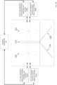
- the pathways shown in FIG. 2 are typical for a plot of land 202 that is to be harvested.
- the combine may employ residue system 70 to perform spreading and/or windrowing of the harvested crops at different locations of the field.
- the combine may start performing spreading along path 204. Once the combine reaches point 208, a turn is made and spreading is performed along path 206. Once the combine reaches point 210, a turn is made and spreading is performed along path 212. Finally, once the combine reaches point 214, a turn is made and windrowing is performed in a zig-zag pattern along path 216.
- the combine controls the speeds of wheels 120 and 122 and/or angles of the wheel paddles 120A/122A-120D/122D in the residue spreading system to achieve a desirable (e.g. uniform) residue spread.
- the speeds of wheels 120 and 122 and/or angles of the wheel paddles 120A/122A-120D/122D may initially be set manually by the combine operator, or they may initially be set by the combine controller.
- the operator may use a number of factors including but not limited to their experience, combine heading, crop type, and weather forecasts (e.g. wind speed/direction).
- the combine controller may use a number of factors including but not limited to past results, combine heading, crop type, weather forecasts (e.g. wind speed/direction) and desired spread characteristics (e.g. density, uniformity, etc.).
- the combine may monitor an observable output such as images of the spread captured by a camera (not shown) mounted to the combine, and automatically adjust the speeds of wheels 120 and 122 and/or angles of the wheel paddles based on observable output of the spreader.
- the initial speeds of wheels 120 and 122 and/or angles of the wheel paddles 120A/122A-120D/122D are set either using predetermined values or based on operator experience.
- the operator is able to visually observe the residue spread. If the residue spread is desirable, the operator can simply continue harvesting. If the residue spread is undesirable, the operator can make adjustments (e.g. oscillation peak range, oscillation frequency, nominal frequency, etc.).
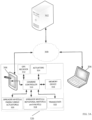
- FIG. 3A shows an example of a system for controlling the combine.
- the system includes an interconnection between a control system 318 of combine 10, a remote PC 306 and a remote server 302 through network 300 (e.g. Internet).
- network 300 e.g. Internet
- combine 10 does not have to be connected to other devices through a network.
- the controller of combine 10 can be a standalone system that receives operating instructions (e.g. speeds of wheels 120 and 122 and/or angles of the wheel paddles 120A/122A-120D/122D) through a user interface, or through a removable memory device (e.g. Flash Drive).
- operating instructions e.g. speeds of wheels 120 and 122 and/or angles of the wheel paddles 120A/122A-120D/122D
- Flash Drive e.g. Flash Drive
- an operator may designate grain information (e.g. type of grain, moisture content of grain, etc.) as well as speeds of wheels 120 and 122 and/or angles of the wheel paddles 120A/122A-120D/122D.
- the operator uses interface 304 of the combine control system or PC 306 located at remote location 308.
- Interface 304 and PC 306 allow the operator to view locally stored parameters from memory device 316 and/or download parameters from server 302 through network 300.
- the operator may select (via Interface 304 or PC 306) appropriate speeds of wheels 120 and 122 and/or angles of the wheel paddles 120A/122A-120D/122D based on various factors including, among others, the type of crop to be harvested by the combine, and the terrain.
- Combine controller 312 controls spreader wheel rotational motors 318 (e.g. electric motors, hydraulic motors, hydraulic valves, etc.) and/or valves and spreader wheel paddle angle actuators 326 based on the instructions. It is noted that harvesting may also be tracked and aided by GPS receiver 312.
- spreader wheel rotational motors 318 e.g. electric motors, hydraulic motors, hydraulic valves, etc.
- valves and spreader wheel paddle angle actuators 326 e.g. electric motors, hydraulic motors, hydraulic valves, etc.
- FIG. 3B is a view of the communication between the combine controller and the spreader wheel drive system, according to an embodiment of the invention.
- combine controller 310 controls left-side spreader wheel rotational motor(s) and/or valves 318A (e.g. electric motors for electrically driven wheels 120/122, or hydraulic valves and/or hydraulic motors for hydraulically driven wheels 120/122) for controlling rotational speed of wheels 120/122, and left-side spreader wheel paddle actuators 326A for controlling radial/pitch angle of paddles 120A/122A-120D/122D.
- Combine controller 310 also controls right-side spreader wheel rotational motor(s) and/or valves 318B (e.g.
- Control of devices 318A/326A may be independent of control of devices 318B/326B.
- devices 318A/326A may be controlled to vary wheel rotational speed and/or paddle angles of the left side spreader according to a first independent algorithm
- devices 318B/326B may be controlled to vary wheel rotational speed and/or paddle angles of the right side spreader according to a second independent algorithm.
- control of devices 318B/326B may be dependent on control of devices 318B/326B and vice versa.
- 318A/326A and 318B/326B may be controlled increase rotational speed of left-side wheel 120 and the rotational speed of right-side wheel 122 in sync with one another.
- 318A/326A may be controlled to increase rotational speed of left-side wheel 120 while 318B/326B is controlled to decrease the rotational speed of right-side wheel 122, and vice versa.
- This alternating type of controller allows peak power consumption of the spreader wheels to be reduced while also allowing power to be recycled in certain scenarios. For example, when the speed of wheel 120 is increased and 122 is decreased, peak power is reduced because only one motor is consuming power at a time.
- the motors driving wheels 120/122 are electric motors, the braking of electric motor 120, for example, will generate electrical power that can be recycled and fed to electric motor 122 (and vice versa) or stored in a battery (not shown) for later use.
- GUI graphical user interface
- zones e.g. spreading zones
- land grade not shown
- current operational mode spreading/windrow modes
- operational parameters/states for the spreader wheels chopper, counter knives, windrow door, spreader wheels, spreader deflectors, etc.
- These parameters e.g. nominal speed/angle values, oscillation period, and oscillation range
- the operator can use a stylus or their finger on the touchscreen to set these parameters.
- FIG. 5A is a flowchart showing a method 500 for controlling the rotational speed of the spreader wheels for achieving a uniform residue spread pattern.
- the controller or operator sets the oscillation parameters (e.g. nominal speed, oscillation period, oscillation speed range) of the spreader wheels.
- the controller controls the electric motors and/or hydraulic valves of the spreader wheels 120/122 to oscillate rational speed of spreader wheels 120/122 based on these parameters. Either the operator observes the output spread or the combine, via a camera (not shown), monitors the output spread in step 503. If the output spread is determined to be desirable (e.g. uniform) in step 504, then the spreading continues using the same parameters. However, if the output spread is determined to be undesirable (e.g. non-uniform) in step 504, then the operator or the controller adjusts one or more of the parameters in step 505 with the goal of achieving a desirable output spread.
- the output spread is determined to be desirable (e.g. uniform) in step 504
- FIG. 5B is a flowchart showing a method 510 for controlling the angles of the spreader wheel paddles for achieving a uniform residue spread pattern.
- the controller or operator sets the oscillation parameters (e.g. nominal paddle angle, oscillation period, oscillation angle range) of the spreader wheel paddles.
- the controller controls the actuators of the paddles to oscillate the angles (e.g. pitch/radial angles) of the paddles based on these parameters.
- the operator observes the output spread or the combine, via a camera (not shown) monitors the output spread in step 513. If the output spread is determined to be desirable (e.g. uniform) in step 514, then the spreading continues using the same parameters. However, if the output spread is determined to be undesirable (e.g. non-uniform) in step 514, then the operator or the controller adjusts one or more of the parameters in step 515 with the goal of achieving a desirable output spread.
- the output spread is determined to be desirable (e.g. uniform) in step 514, then
- FIGS. 5A and 5B are described with respect to achieving a uniform spread, there could be scenarios where a non-uniform spread is desirable.
- the operator or the controller adjusts sets/adjusts the parameters with the goal of achieving a non-uniform spread. This may include an oscillation behavior that is not symmetrical like the sinusoidal behavior shown in FIG. 4 .
- FIGS. 5A and 5B are described as separately controlling the rotational speed of the spreader wheels and the angles of the paddles, these control methods could be combined.
- the operator or controller could set both oscillation rotational speed parameters and oscillation paddle angle parameters.
- the controller could then oscillate both the rotational speed and the paddle angles in a manner that produces a uniform output spread (e.g. rational speed and paddle angle can decrease/ increase at the same time).
- Steps 501-515 of FIGS. 5A and 5B are performed by controller 310 upon loading and executing software code or instructions which are tangibly stored on a tangible computer readable medium 316, such as on a magnetic medium, e.g., a computer hard drive, an optical medium, e.g., an optical disc, solid-state memory, e.g., flash memory, or other storage media known in the art.
- a tangible computer readable medium 316 such as on a magnetic medium, e.g., a computer hard drive, an optical medium, e.g., an optical disc, solid-state memory, e.g., flash memory, or other storage media known in the art.
- any of the functionality performed by the controller 310 described herein, such as the steps shown in FIGS. 5A and 5B are implemented in software code or instructions which are tangibly stored on a tangible computer readable medium.
- the controller 310 may perform any of the functionality of the controller 310 described herein, including the steps shown in FIGS. 5
- the operational steps are performed by the controller 310 upon loading and executing software code or instructions which are tangibly stored on a tangible computer readable medium, such as on a magnetic medium, e.g., a computer hard drive, an optical medium, e.g., an optical disc, solid-state memory, e.g., flash memory, or other storage media known in the art.
- a tangible computer readable medium such as on a magnetic medium, e.g., a computer hard drive, an optical medium, e.g., an optical disc, solid-state memory, e.g., flash memory, or other storage media known in the art.
- any of the functionality performed by the controller 310 described herein is implemented in software code or instructions which are tangibly stored on a tangible computer readable medium.
- the controller 310 may perform any of the functionality of the controller 310 described herein, including any steps of the methods described herein.
- software code or “code” used herein refers to any instructions or set of instructions that influence the operation of a computer or controller. They may exist in a computer-executable form, such as machine code, which is the set of instructions and data directly executed by a computer's central processing unit or by a controller, a human-understandable form, such as source code, which may be compiled in order to be executed by a computer's central processing unit or by a controller, or an intermediate form, such as object code, which is produced by a compiler.
- the term "software code” or “code” also includes any human-understandable computer instructions or set of instructions, e.g., a script, that may be executed on the fly with the aid of an interpreter executed by a computer's central processing unit or by a controller.
Landscapes
- Life Sciences & Earth Sciences (AREA)
- Environmental Sciences (AREA)
- Guiding Agricultural Machines (AREA)
- Harvester Elements (AREA)
Claims (15)
- Mähdrescher (10) mit:einem Zuführgehäuse (20) zur Aufnahme von geerntetem Erntegut;einem Abscheidesystem (24) zum Dreschen des geernteten Ernteguts, um Korn von Reststoffen zu trennen;einer Reststoffverteilerscheibe (120, 122), die zum Verteilen der Reststoffe des Mähdreschers (10) rotiert; undeinem Steuergerät (310), das den Mähdrescher (10) steuert,dadurch gekennzeichnet, dassdas Steuergerät (310) dazu eingerichtet ist, die Reststoffverteilerscheibe (120, 122) während des Verteilens von Reststoffen zu steuern, dass sie kontinuierlich zwischen einer ersten Geschwindigkeit, die kleiner als eine Nominalgeschwindigkeit ist, und einer zweiten Geschwindigkeit, die größer als die Nominalgeschwindigkeit ist, oszilliert.
- Mähdrescher (10) nach Anspruch 1, wobei der Mähdrescher (10) eine weitere Reststoffverteilerscheibe (120, 122) umfasst, die zum Verteilen der Reststoffe des Mähdreschers (10) rotiert, und wobei das Steuergerät (310) des Weiteren dazu eingerichtet ist, die weitere Reststoffverteilerscheibe (120, 122) während des Verteilens der Reststoffe zu steuern, dass sie kontinuierlich zwischen der ersten Geschwindigkeit, die kleiner als die Nominalgeschwindigkeit ist, und der zweiten Geschwindigkeit, die größer als die Nominalgeschwindigkeit ist, oszilliert, und wobei das Steuergerät (310) des Weiteren dazu eingerichtet ist, die Geschwindigkeiten der Reststoffverteilerscheibe (120, 122) und der weiteren Reststoffverteilerscheibe (120, 122) derart zu steuern, dass, wenn die Drehgeschwindigkeit der Reststoffverteilerscheibe (120, 122) zunimmt, die Drehgeschwindigkeit der weiteren Reststoffverteilerscheibe (120, 122) abnimmt.
- Mähdrescher (10) nach Anspruch 1 oder 2, wobei der Mähdrescher (10) einen Elektromotor (318) zum Rotieren der Reststoffverteilerscheibe (120, 122) umfasst, wobei das Steuergerät (310) kontinuierlich einen elektrischen Strom, der dem Elektromotor (318) zugeführt wird, variiert, um die Reststoffverteilerscheibe (120, 122) zum kontinuierlichen Oszillieren zwischen der ersten Geschwindigkeit und der zweiten Geschwindigkeit steuern, wobei das Steuergerät (310) des Weiteren dazu eingerichtet ist, eine elektrische Leistung, die von dem Elektromotor (318) erzeugt wird, zu speichern, wenn die Drehgeschwindigkeit der Reststoffverteilerscheibe abnimmt.
- Mähdrescher (10) nach Anspruch 2, wobei der Mähdrescher (10) einen Hydraulikmotor (318) zum Rotieren der Reststoffverteilerscheibe (120, 122) umfasst, wobei das Steuergerät (310) kontinuierlich einen Hydraulikdruck, der dem Hydraulikmotor (318) bereitgestellt wird, variiert, um die Reststoffverteilerscheibe (120, 122) zum kontinuierlich Oszillieren zwischen der ersten Geschwindigkeit und der zweiten Geschwindigkeit zu steuern, und wobei das Steuergerät (310) des Weiteren eingerichtet ist zum:Umleiten des Hydraulikdrucks zum Antreiben eines weiteren Hydraulikmotors (318) der weiteren Reststoffverteilerscheibe (120, 122), wenn die Drehgeschwindigkeit der Reststoffverteilerscheibe (120, 122) abnimmt, undUmleiten des Hydraulikdrucks zum Antreiben des Hydraulikmotors (318) der Reststoffverteilerscheibe (120, 122), wenn die Drehgeschwindigkeit der weiteren Reststoffverteilerscheibe (120, 122) abnimmt.
- Mähdrescher (10) nach einem der Ansprüche 1 bis 4, wobei das Steuergerät (310) des Weiteren eingerichtet ist zum:Empfangen einer Reststoffverteilungsmuster-Rückmeldung von einem Sensor (115A, 115B, 115C, 115D) oder von einer Bedienperson des Mähdreschers (10), undSteuern der Reststoffverteilerscheibe (120, 122), um das Reststoffverteilungsmuster basierend auf der Rückmeldung zu modifizieren.
- Mähdrescher (10) nach Anspruch 5, wobei das Steuergerät (310) des Weiteren eingerichtet ist zum Verstellen zumindest einer aus einer Nominalgeschwindigkeit, der ersten Geschwindigkeit, der zweiten Geschwindigkeit oder der Frequenz einer Oszillation, um das Reststoffverteilungsmuster basierend auf der Rückmeldung zu modifizieren.
- Mähdrescher (10) nach einem der vorhergehenden Ansprüche, wobei die Reststoffverteilerscheibe (120, 122) Schaufeln (120A, 120B, 120C, 120D, 122A, 122B, 122C, 122D) aufweist, die sich in einem Winkel zum Verteilen der Reststoffe von dem Mähdrescher (10) erstrecken, und wobei das Steuergerät (310) des Weiteren dazu eingerichtet ist, die Schaufeln (120A, 120B, 120C, 120D, 122A, 122B, 122C, 122D) der Reststoffverteilerscheibe (120, 122) während des Verteilens der Reststoffe zum kontinuierlichen Oszillieren zwischen einem ersten Winkel, der kleiner als ein nominaler Winkel ist, und einem zweiten Winkel, der größer als der nominale Winkel ist, zu steuern.
- Mähdrescher (10) nach Anspruch 7, wenn direkt oder indirekt abhängig von Anspruch 2, wobei das Steuergerät (310) des Weiteren eingerichtet ist zum alternierenden Steuern der Winkel der Schaufeln (120A, 120B, 120C, 120D, 122A, 122B, 122C, 122D) der Reststoffverteilerscheibe (120, 122) und der Schaufeln (120A, 120B, 120C, 120D, 122A, 122B, 122C, 122D) der weiteren Reststoffverteilerscheibe (120, 122), so dass, wenn der Winkel der Reststoffverteilerscheibe (120, 122) sich vergrößert, der Winkel der weiteren Reststoffverteilerscheibe (120, 122) abnimmt.
- Mähdrescher (10) nach Anspruch 7 oder 8, wobei der Mähdrescher (10) einen Elektromotor (318) zum Variieren des Winkels der Schaufeln (120A, 120B, 120C, 120D, 122A, 122B, 122C, 122D) der Reststoffverteilerscheibe (120, 122) umfasst, und wobei das Steuergerät (310) kontinuierlich einen elektrischen Strom, der dem Elektromotor (318) bereitgestellt ist, zum Steuern der Schaufeln (120A, 120B, 120C, 120D, 122A, 122B, 122C, 122D) der Reststoffverteilerscheibe (120, 122) zum kontinuierlichen Oszillieren zwischen dem ersten Winkel und dem zweiten Winkel variiert.
- Mähdrescher (10) nach einem der Ansprüche 7 bis 9, wobei der Winkel der Schaufeln (120A, 120B, 120C, 120D, 122A, 122B, 122C, 122D) ein Neigungswinkel der Schaufeln (120A, 120B, 120C, 120D, 122A, 122B, 122C, 122D) relativ zu einer Rotationsebene der Reststoffverteilerscheibe (120, 122) ist.
- Mähdrescher (10) nach einem der Ansprüche 7 bis 10, wobei der Winkel der Schaufeln (120A, 120B, 120C, 120D, 122A, 122B, 122C, 122D) ein Taumelwinkel der Schaufeln (120A, 120B, 120C, 120D, 122A, 122B, 122C, 122D) relativ zu einer Achse auf einer Rotationsebene der Reststoffverteilerscheibe (120, 122) ist, die eine Rotationsachse der Reststoffverteilerscheibe (120, 122) schneidet.
- Mähdrescher (10) nach einem der Ansprüche 7, 8, 10 oder 11, wobei der Mähdrescher (10) einen Hydraulikmotor (318) zum Variieren des Winkels der Schaufeln (120A, 120B, 120C, 120D, 122A, 122B, 122C, 122D) der Reststoffverteilerscheibe (120, 122) umfasst, und wobei das Steuergerät (310) periodisch einen Hydraulikdruck, der dem Hydraulikmotor (318) bereitgestellt wird, zum Steuern der Schaufeln (120A, 120B, 120C, 120D, 122A, 122B, 122C, 122D) der Reststoffverteilerscheibe (120, 122) zum kontinuierlichen Oszillieren zwischen dem ersten Winkel und dem zweiten Winkel umleitet.
- Mähdrescher (10) nach Anspruch 12, wenn direkt oder indirekt abhängig von Anspruch 8, wobei das Steuergerät (310) des Weiteren eingerichtet ist zum:
Leiten des Hydraulikdrucks zum Antreiben eines weiteren Hydraulikmotors (318) der weiteren Reststoffverteilerscheibe (120, 122), wenn ein Winkel der Schaufeln (120A, 120B, 120C, 120D, 122A, 122B, 122C, 122D) der weiteren Reststoffverteilerscheibe (120, 122) zunimmt, wenn der Winkel der Schaufeln (120A, 120B, 120C, 120D, 122A, 122B, 122C, 122D) der Reststoffverteilerscheibe (120, 122) abnimmt. - Mähdrescher (10) nach einem der Ansprüche 7 bis 13, wobei das Steuergerät (310) des Weiteren eingerichtet ist zum:Empfangen von Reststoffverteilungsmuster-Rückmeldungen von einem Sensor (115A, 115B, 115C, 115D) oder von einer Bedienperson des Mähdreschers (10), undSteuern der Reststoffverteilerscheibe (120, 122), um das Reststoffverteilungsmusters basierend auf der Rückmeldung zu modifizieren.
- Mähdrescher (10) nach Anspruch 14, wobei das Steuergerät (310) des Weiteren dazu eingerichtet ist, zumindest einen aus dem nominalen Winkel, dem ersten Winkel, dem zweiten Winkel oder der Frequenz einer Oszillation zu verstellen, um das Reststoffverteilungsmuster basierend auf der Rückmeldung zu modifizieren.
Applications Claiming Priority (1)
| Application Number | Priority Date | Filing Date | Title |
|---|---|---|---|
| US17/466,226 US12232452B2 (en) | 2021-09-03 | 2021-09-03 | Control of residue spread pattern by continuously varying distribution frequency |
Publications (2)
| Publication Number | Publication Date |
|---|---|
| EP4144201A1 EP4144201A1 (de) | 2023-03-08 |
| EP4144201B1 true EP4144201B1 (de) | 2025-01-15 |
Family
ID=83192158
Family Applications (1)
| Application Number | Title | Priority Date | Filing Date |
|---|---|---|---|
| EP22193778.2A Active EP4144201B1 (de) | 2021-09-03 | 2022-09-02 | Steuerung des streumusters von rückständen durch kontinuierliche änderung der verteilungsfrequenz |
Country Status (4)
| Country | Link |
|---|---|
| US (1) | US12232452B2 (de) |
| EP (1) | EP4144201B1 (de) |
| AR (1) | AR126910A1 (de) |
| BR (1) | BR102022017630A2 (de) |
Families Citing this family (1)
| Publication number | Priority date | Publication date | Assignee | Title |
|---|---|---|---|---|
| EP4101284B1 (de) * | 2021-06-09 | 2025-12-17 | CNH Industrial Belgium N.V. | Mähdrescher mit geneigter erntegutsensoranordnung |
Family Cites Families (22)
| Publication number | Priority date | Publication date | Assignee | Title |
|---|---|---|---|---|
| CA1144031A (en) | 1981-06-03 | 1983-04-05 | Guy Delorme | Straw spreader |
| DE3723932A1 (de) | 1987-07-20 | 1989-02-02 | Henkel Kgaa | Klebeverfahren fuer wasserdampfdurchlaessige substrate |
| US5797793A (en) * | 1996-03-07 | 1998-08-25 | Case Corporation | Residue spreading apparatus for agricultural combines |
| US7306174B2 (en) * | 2004-03-04 | 2007-12-11 | Deere & Company | Broadcast width and location control for a combine spreader |
| US7223168B2 (en) * | 2005-08-01 | 2007-05-29 | Cnh America Llc | Adjustable crop residue flow distributor for a vertical spreader of an agricultural combine |
| US7390253B2 (en) * | 2006-05-25 | 2008-06-24 | Cnh America Llc | Flow distributor apparatus for controlling spread width of a straw spreader |
| US20090287380A1 (en) * | 2008-05-15 | 2009-11-19 | Chervenka Kirk J | Work machine, system and method for broadcast spreading of a material in wind conditions |
| EP2266381A1 (de) | 2009-06-23 | 2010-12-29 | Agro-Ingenjör AB | Verbesserter Streuer zum Streuen von Stroh und Ernteresten |
| US8010262B2 (en) * | 2009-10-21 | 2011-08-30 | Cnh America Llc | Apparatus and method for automatically controlling the settings of an adjustable crop residue spreader of an agricultural combine |
| US8118650B2 (en) * | 2010-03-24 | 2012-02-21 | Cnh America Llc | Crop residue flow distributor for an agricultural combine |
| US20130095899A1 (en) * | 2011-10-18 | 2013-04-18 | Cnh America Llc | Wind compensation of residue spread width |
| US10143131B2 (en) * | 2011-10-18 | 2018-12-04 | Cnh Industrial America Llc | Method and apparatus to control residue width |
| US9974232B2 (en) | 2014-06-06 | 2018-05-22 | Cnh Industrial America Llc | Spreader width control |
| US9313950B2 (en) * | 2014-09-19 | 2016-04-19 | Cnh Industrial America Llc | Multi-purpose spreader of an agricultural vehicle |
| DE102014113965A1 (de) | 2014-09-26 | 2016-03-31 | Claas Selbstfahrende Erntemaschinen Gmbh | Mähdrescher mit Fahrerassistenzsystem |
| US9699967B2 (en) | 2015-09-25 | 2017-07-11 | Deere & Company | Crosswind compensation for residue processing |
| US9894836B2 (en) * | 2016-01-14 | 2018-02-20 | Deere & Company | Machine operation enhancement |
| BE1025043B1 (nl) * | 2017-03-09 | 2018-10-11 | Cnh Industrial Belgium Nv | Strooisysteem voor een oogstmachine voor landbouwtoepassingen met een heen- en weergaande deflector |
| BE1025041B1 (nl) | 2017-03-09 | 2018-10-11 | Cnh Industrial Belgium Nv | Controlesysteem voor een oogstmachine en oogstmachine |
| US10448576B2 (en) * | 2017-08-22 | 2019-10-22 | Cnh Industrial America Llc | Adjustable fan based on grain throughput |
| BR102019009913A2 (pt) * | 2018-05-17 | 2020-05-05 | Cnh Ind America Llc | descarga de resíduo a partir de uma ceifeira-debulhadora |
| US10820502B2 (en) * | 2018-10-01 | 2020-11-03 | Cnh Industrial America Llc | Compensation method for wind effects upon residue distribution |
-
2021
- 2021-09-03 US US17/466,226 patent/US12232452B2/en active Active
-
2022
- 2022-08-29 AR ARP220102329A patent/AR126910A1/es unknown
- 2022-09-02 BR BR102022017630-2A patent/BR102022017630A2/pt unknown
- 2022-09-02 EP EP22193778.2A patent/EP4144201B1/de active Active
Also Published As
| Publication number | Publication date |
|---|---|
| EP4144201A1 (de) | 2023-03-08 |
| US20230076080A1 (en) | 2023-03-09 |
| US12232452B2 (en) | 2025-02-25 |
| AR126910A1 (es) | 2023-11-29 |
| BR102022017630A2 (pt) | 2023-03-21 |
Similar Documents
| Publication | Publication Date | Title |
|---|---|---|
| EP3632199B1 (de) | Verfahren zur kompensation von windeffekten bei der verteilung von ernterückständen | |
| EP3672391B1 (de) | Verstellbares gebläse auf der grundlage des korndurchsatzes | |
| US11547048B2 (en) | Spreader system for an agricultural harvester with an oscillating deflector | |
| EP3597028B1 (de) | Gebläseantrieb in abhängigkeit von der last auf den reinigungsgebläseantrieb | |
| US11240958B2 (en) | Discharging residue from a combine harvester | |
| EP4101287B1 (de) | Steuerung einer häckselanordnung für eine landwirtschaftliche erntemaschine | |
| EP3687276B1 (de) | Automatische häckselwannensteuerung | |
| EP3236740A2 (de) | Rückstandhandhabungssystem für eine landwirtschaftliche erntemaschine | |
| EP3634109B1 (de) | Spreu-/strohverteilersystem für landwirtschaftliche erntemaschine | |
| EP4144201B1 (de) | Steuerung des streumusters von rückständen durch kontinuierliche änderung der verteilungsfrequenz | |
| EP3485720B1 (de) | Verstellbare zuführschaufeln | |
| EP3345472B1 (de) | Ernterückstandverteiler für einen mähdrescher |
Legal Events
| Date | Code | Title | Description |
|---|---|---|---|
| PUAI | Public reference made under article 153(3) epc to a published international application that has entered the european phase |
Free format text: ORIGINAL CODE: 0009012 |
|
| STAA | Information on the status of an ep patent application or granted ep patent |
Free format text: STATUS: THE APPLICATION HAS BEEN PUBLISHED |
|
| AK | Designated contracting states |
Kind code of ref document: A1 Designated state(s): AL AT BE BG CH CY CZ DE DK EE ES FI FR GB GR HR HU IE IS IT LI LT LU LV MC MK MT NL NO PL PT RO RS SE SI SK SM TR |
|
| STAA | Information on the status of an ep patent application or granted ep patent |
Free format text: STATUS: REQUEST FOR EXAMINATION WAS MADE |
|
| 17P | Request for examination filed |
Effective date: 20230908 |
|
| RBV | Designated contracting states (corrected) |
Designated state(s): AL AT BE BG CH CY CZ DE DK EE ES FI FR GB GR HR HU IE IS IT LI LT LU LV MC MK MT NL NO PL PT RO RS SE SI SK SM TR |
|
| GRAP | Despatch of communication of intention to grant a patent |
Free format text: ORIGINAL CODE: EPIDOSNIGR1 |
|
| STAA | Information on the status of an ep patent application or granted ep patent |
Free format text: STATUS: GRANT OF PATENT IS INTENDED |
|
| INTG | Intention to grant announced |
Effective date: 20240805 |
|
| GRAS | Grant fee paid |
Free format text: ORIGINAL CODE: EPIDOSNIGR3 |
|
| GRAA | (expected) grant |
Free format text: ORIGINAL CODE: 0009210 |
|
| STAA | Information on the status of an ep patent application or granted ep patent |
Free format text: STATUS: THE PATENT HAS BEEN GRANTED |
|
| AK | Designated contracting states |
Kind code of ref document: B1 Designated state(s): AL AT BE BG CH CY CZ DE DK EE ES FI FR GB GR HR HU IE IS IT LI LT LU LV MC MK MT NL NO PL PT RO RS SE SI SK SM TR |
|
| REG | Reference to a national code |
Ref country code: CH Ref legal event code: EP Ref country code: GB Ref legal event code: FG4D |
|
| REG | Reference to a national code |
Ref country code: DE Ref legal event code: R096 Ref document number: 602022009525 Country of ref document: DE |
|
| REG | Reference to a national code |
Ref country code: IE Ref legal event code: FG4D |
|
| REG | Reference to a national code |
Ref country code: NL Ref legal event code: MP Effective date: 20250115 |
|
| PG25 | Lapsed in a contracting state [announced via postgrant information from national office to epo] |
Ref country code: NL Free format text: LAPSE BECAUSE OF FAILURE TO SUBMIT A TRANSLATION OF THE DESCRIPTION OR TO PAY THE FEE WITHIN THE PRESCRIBED TIME-LIMIT Effective date: 20250115 |
|
| PG25 | Lapsed in a contracting state [announced via postgrant information from national office to epo] |
Ref country code: RS Free format text: LAPSE BECAUSE OF FAILURE TO SUBMIT A TRANSLATION OF THE DESCRIPTION OR TO PAY THE FEE WITHIN THE PRESCRIBED TIME-LIMIT Effective date: 20250415 |
|
| PG25 | Lapsed in a contracting state [announced via postgrant information from national office to epo] |
Ref country code: FI Free format text: LAPSE BECAUSE OF FAILURE TO SUBMIT A TRANSLATION OF THE DESCRIPTION OR TO PAY THE FEE WITHIN THE PRESCRIBED TIME-LIMIT Effective date: 20250115 |
|
| PG25 | Lapsed in a contracting state [announced via postgrant information from national office to epo] |
Ref country code: PL Free format text: LAPSE BECAUSE OF FAILURE TO SUBMIT A TRANSLATION OF THE DESCRIPTION OR TO PAY THE FEE WITHIN THE PRESCRIBED TIME-LIMIT Effective date: 20250115 |
|
| PG25 | Lapsed in a contracting state [announced via postgrant information from national office to epo] |
Ref country code: ES Free format text: LAPSE BECAUSE OF FAILURE TO SUBMIT A TRANSLATION OF THE DESCRIPTION OR TO PAY THE FEE WITHIN THE PRESCRIBED TIME-LIMIT Effective date: 20250115 |
|
| REG | Reference to a national code |
Ref country code: LT Ref legal event code: MG9D |
|
| PG25 | Lapsed in a contracting state [announced via postgrant information from national office to epo] |
Ref country code: NO Free format text: LAPSE BECAUSE OF FAILURE TO SUBMIT A TRANSLATION OF THE DESCRIPTION OR TO PAY THE FEE WITHIN THE PRESCRIBED TIME-LIMIT Effective date: 20250415 Ref country code: IS Free format text: LAPSE BECAUSE OF FAILURE TO SUBMIT A TRANSLATION OF THE DESCRIPTION OR TO PAY THE FEE WITHIN THE PRESCRIBED TIME-LIMIT Effective date: 20250515 |
|
| REG | Reference to a national code |
Ref country code: AT Ref legal event code: MK05 Ref document number: 1759184 Country of ref document: AT Kind code of ref document: T Effective date: 20250115 |
|
| PG25 | Lapsed in a contracting state [announced via postgrant information from national office to epo] |
Ref country code: HR Free format text: LAPSE BECAUSE OF FAILURE TO SUBMIT A TRANSLATION OF THE DESCRIPTION OR TO PAY THE FEE WITHIN THE PRESCRIBED TIME-LIMIT Effective date: 20250115 |
|
| PG25 | Lapsed in a contracting state [announced via postgrant information from national office to epo] |
Ref country code: PT Free format text: LAPSE BECAUSE OF FAILURE TO SUBMIT A TRANSLATION OF THE DESCRIPTION OR TO PAY THE FEE WITHIN THE PRESCRIBED TIME-LIMIT Effective date: 20250515 Ref country code: LV Free format text: LAPSE BECAUSE OF FAILURE TO SUBMIT A TRANSLATION OF THE DESCRIPTION OR TO PAY THE FEE WITHIN THE PRESCRIBED TIME-LIMIT Effective date: 20250115 |
|
| PG25 | Lapsed in a contracting state [announced via postgrant information from national office to epo] |
Ref country code: GR Free format text: LAPSE BECAUSE OF FAILURE TO SUBMIT A TRANSLATION OF THE DESCRIPTION OR TO PAY THE FEE WITHIN THE PRESCRIBED TIME-LIMIT Effective date: 20250416 Ref country code: BG Free format text: LAPSE BECAUSE OF FAILURE TO SUBMIT A TRANSLATION OF THE DESCRIPTION OR TO PAY THE FEE WITHIN THE PRESCRIBED TIME-LIMIT Effective date: 20250115 |
|
| PG25 | Lapsed in a contracting state [announced via postgrant information from national office to epo] |
Ref country code: AT Free format text: LAPSE BECAUSE OF FAILURE TO SUBMIT A TRANSLATION OF THE DESCRIPTION OR TO PAY THE FEE WITHIN THE PRESCRIBED TIME-LIMIT Effective date: 20250115 |
|
| PG25 | Lapsed in a contracting state [announced via postgrant information from national office to epo] |
Ref country code: SE Free format text: LAPSE BECAUSE OF FAILURE TO SUBMIT A TRANSLATION OF THE DESCRIPTION OR TO PAY THE FEE WITHIN THE PRESCRIBED TIME-LIMIT Effective date: 20250115 |
|
| PG25 | Lapsed in a contracting state [announced via postgrant information from national office to epo] |
Ref country code: SM Free format text: LAPSE BECAUSE OF FAILURE TO SUBMIT A TRANSLATION OF THE DESCRIPTION OR TO PAY THE FEE WITHIN THE PRESCRIBED TIME-LIMIT Effective date: 20250115 |
|
| PG25 | Lapsed in a contracting state [announced via postgrant information from national office to epo] |
Ref country code: DK Free format text: LAPSE BECAUSE OF FAILURE TO SUBMIT A TRANSLATION OF THE DESCRIPTION OR TO PAY THE FEE WITHIN THE PRESCRIBED TIME-LIMIT Effective date: 20250115 |
|
| PGFP | Annual fee paid to national office [announced via postgrant information from national office to epo] |
Ref country code: DE Payment date: 20250926 Year of fee payment: 4 |
|
| PG25 | Lapsed in a contracting state [announced via postgrant information from national office to epo] |
Ref country code: IT Free format text: LAPSE BECAUSE OF FAILURE TO SUBMIT A TRANSLATION OF THE DESCRIPTION OR TO PAY THE FEE WITHIN THE PRESCRIBED TIME-LIMIT Effective date: 20250115 |
|
| REG | Reference to a national code |
Ref country code: DE Ref legal event code: R097 Ref document number: 602022009525 Country of ref document: DE |
|
| PGFP | Annual fee paid to national office [announced via postgrant information from national office to epo] |
Ref country code: FR Payment date: 20250925 Year of fee payment: 4 |
|
| PG25 | Lapsed in a contracting state [announced via postgrant information from national office to epo] |
Ref country code: CZ Free format text: LAPSE BECAUSE OF FAILURE TO SUBMIT A TRANSLATION OF THE DESCRIPTION OR TO PAY THE FEE WITHIN THE PRESCRIBED TIME-LIMIT Effective date: 20250115 Ref country code: EE Free format text: LAPSE BECAUSE OF FAILURE TO SUBMIT A TRANSLATION OF THE DESCRIPTION OR TO PAY THE FEE WITHIN THE PRESCRIBED TIME-LIMIT Effective date: 20250115 |
|
| PG25 | Lapsed in a contracting state [announced via postgrant information from national office to epo] |
Ref country code: RO Free format text: LAPSE BECAUSE OF FAILURE TO SUBMIT A TRANSLATION OF THE DESCRIPTION OR TO PAY THE FEE WITHIN THE PRESCRIBED TIME-LIMIT Effective date: 20250115 |
|
| PG25 | Lapsed in a contracting state [announced via postgrant information from national office to epo] |
Ref country code: SK Free format text: LAPSE BECAUSE OF FAILURE TO SUBMIT A TRANSLATION OF THE DESCRIPTION OR TO PAY THE FEE WITHIN THE PRESCRIBED TIME-LIMIT Effective date: 20250115 |
|
| PLBE | No opposition filed within time limit |
Free format text: ORIGINAL CODE: 0009261 |
|
| STAA | Information on the status of an ep patent application or granted ep patent |
Free format text: STATUS: NO OPPOSITION FILED WITHIN TIME LIMIT |
|
| 26N | No opposition filed |
Effective date: 20251016 |