EP4143949B1 - Stator einer elektrischen maschine - Google Patents
Stator einer elektrischen maschine Download PDFInfo
- Publication number
- EP4143949B1 EP4143949B1 EP21715181.0A EP21715181A EP4143949B1 EP 4143949 B1 EP4143949 B1 EP 4143949B1 EP 21715181 A EP21715181 A EP 21715181A EP 4143949 B1 EP4143949 B1 EP 4143949B1
- Authority
- EP
- European Patent Office
- Prior art keywords
- stator
- laminations
- lamination
- teeth
- slot
- Prior art date
- Legal status (The legal status is an assumption and is not a legal conclusion. Google has not performed a legal analysis and makes no representation as to the accuracy of the status listed.)
- Active
Links
Images


Classifications
-
- H—ELECTRICITY
- H02—GENERATION; CONVERSION OR DISTRIBUTION OF ELECTRIC POWER
- H02K—DYNAMO-ELECTRIC MACHINES
- H02K1/00—Details of the magnetic circuit
- H02K1/06—Details of the magnetic circuit characterised by the shape, form or construction
- H02K1/12—Stationary parts of the magnetic circuit
- H02K1/16—Stator cores with slots for windings
-
- H—ELECTRICITY
- H02—GENERATION; CONVERSION OR DISTRIBUTION OF ELECTRIC POWER
- H02K—DYNAMO-ELECTRIC MACHINES
- H02K1/00—Details of the magnetic circuit
- H02K1/06—Details of the magnetic circuit characterised by the shape, form or construction
- H02K1/12—Stationary parts of the magnetic circuit
- H02K1/16—Stator cores with slots for windings
- H02K1/165—Shape, form or location of the slots
-
- H—ELECTRICITY
- H02—GENERATION; CONVERSION OR DISTRIBUTION OF ELECTRIC POWER
- H02K—DYNAMO-ELECTRIC MACHINES
- H02K15/00—Processes or apparatus specially adapted for manufacturing, assembling, maintaining or repairing of dynamo-electric machines
- H02K15/02—Processes or apparatus specially adapted for manufacturing, assembling, maintaining or repairing of dynamo-electric machines of stator or rotor bodies
- H02K15/021—Magnetic cores
-
- H—ELECTRICITY
- H02—GENERATION; CONVERSION OR DISTRIBUTION OF ELECTRIC POWER
- H02K—DYNAMO-ELECTRIC MACHINES
- H02K15/00—Processes or apparatus specially adapted for manufacturing, assembling, maintaining or repairing of dynamo-electric machines
- H02K15/08—Forming windings by laying conductors into or around core parts
- H02K15/085—Forming windings by laying conductors into or around core parts by laying conductors into slotted stators
-
- H—ELECTRICITY
- H02—GENERATION; CONVERSION OR DISTRIBUTION OF ELECTRIC POWER
- H02K—DYNAMO-ELECTRIC MACHINES
- H02K15/00—Processes or apparatus specially adapted for manufacturing, assembling, maintaining or repairing of dynamo-electric machines
- H02K15/10—Applying solid insulation to windings, stators or rotors, e.g. applying insulating tapes
-
- H—ELECTRICITY
- H02—GENERATION; CONVERSION OR DISTRIBUTION OF ELECTRIC POWER
- H02K—DYNAMO-ELECTRIC MACHINES
- H02K3/00—Details of windings
- H02K3/04—Windings characterised by the conductor shape, form or construction, e.g. with bar conductors
- H02K3/12—Windings characterised by the conductor shape, form or construction, e.g. with bar conductors arranged in slots
-
- H—ELECTRICITY
- H02—GENERATION; CONVERSION OR DISTRIBUTION OF ELECTRIC POWER
- H02K—DYNAMO-ELECTRIC MACHINES
- H02K3/00—Details of windings
- H02K3/32—Windings characterised by the shape, form or construction of the insulation
- H02K3/34—Windings characterised by the shape, form or construction of the insulation between conductors or between conductor and core, e.g. slot insulation
- H02K3/345—Windings characterised by the shape, form or construction of the insulation between conductors or between conductor and core, e.g. slot insulation between conductor and core, e.g. slot insulation
-
- H—ELECTRICITY
- H02—GENERATION; CONVERSION OR DISTRIBUTION OF ELECTRIC POWER
- H02K—DYNAMO-ELECTRIC MACHINES
- H02K2201/00—Specific aspects not provided for in the other groups of this subclass relating to the magnetic circuits
- H02K2201/06—Magnetic cores, or permanent magnets characterised by their skew
Definitions
- the invention is based on a stator of an electrical machine according to the preamble of claim 1.
- stator laminated core having a stator axis, which comprises a plurality of stator teeth and a plurality of stator slots formed between the stator teeth and is formed by a plurality of stacked stator laminations, and with electrical conductor elements which run through the stator slots of the stator laminated core and are provided for forming an electrical winding, in particular a plug-in winding, wherein a slot insulation, in particular a slot insulation paper, is provided in each of the stator slots for electrically insulating the conductor elements from the stator laminated core, wherein the stator laminations each have a plurality of lamination teeth and each have a lamination yoke connecting the lamination teeth, wherein the stator teeth of the stator laminated core are each formed by stacked lamination teeth of the stator laminations.
- a gap forms between the conductor elements and the stator lamination stack, or between the conductor elements and the respective slot insulation.
- This gap depends, among other things, on the manufacturing tolerance of the width of the stator slots and the manufacturing tolerance of the width of the conductor elements.
- This gap which is an air gap, possibly filled with an impregnating agent, impairs the heat transfer from the conductor elements to the stator lamination stack.
- the stator of the electrical machine according to the invention with the characterizing features of the main claim has the advantage that the heat transfer from the conductor elements to the stator laminated core and thus the Cooling of the electrical winding is improved. As a result, the performance of the electrical machine can be increased. Furthermore, the mechanical fixation of the conductor elements in the stator slot is also improved, eliminating the need for impregnation of the conductor elements in the stator slot. Furthermore, the manufacturing tolerances for the stator laminations and the conductor elements can be expanded, thus reducing stator manufacturing costs.
- stator according to claim 1.
- at least one stator lamination is provided in the stator core, which lamination is rotated in the circumferential direction relative to the stator axis relative to other stator laminations of the stator core such that, in each stator slot of the stator core, it protrudes into the respective stator slot with a lamination tooth section of one of the lamination teeth.
- the protruding lamination tooth sections form protruding ribs in the stator slots, which have no or only a small gap to the conductor elements.
- each stator slot protrudes into the respective stator slot with the laminar tooth section on one of the two stator teeth delimiting the respective stator slot and that a depression with a negative contour corresponding to the protruding laminar tooth section is formed on the other stator tooth delimiting the respective stator slot.
- stator laminations in the stator lamination stack are rotated in the circumferential direction relative to the stator axis relative to other stator laminations of the stator lamination stack, namely in the same direction of rotation. This further improves the heat transfer from the conductor elements to the stator lamination stack and also the mechanical fixation of the conductor elements in the respective stator slot.
- the plurality of twisted stator laminations in the Stator lamination stack are arranged in several spaced-apart groups of adjacent stator laminations, with two groups of twisted stator laminations there is one or more non-twisted stator laminations.
- the plurality of twisted stator laminations are arranged in the stator laminated core in a plurality of spaced-apart groups of adjacent stator laminations, with one or more non-twisted stator laminations being located between each group of twisted stator laminations.
- the plurality of twisted stator laminations are arranged individually in the stator laminated core, with one or more non-twisted stator laminations being located between each two twisted stator laminations.
- the invention also provides that the multiple twisted stator laminations of the stator core are all twisted by the same angle. This results in a non-skewed stator.
- stator slots provided with the conductor elements have cavities which are at least partially filled with an impregnating agent.
- stator laminations of the stator laminated core are joined together, in particular welded, and/or form an interference fit with a stator housing of the electrical machine on the outer circumference, and/or are clamped between two bearing plates of the electrical machine in the axial direction relative to the stator axis. In this way, the stator laminations of the stator laminated core are fixed in their position.
- stator laminations In a method for producing the stator or the electrical machine, which is not part of the claimed invention, it is provided that after the conductor elements have been inserted and before the stator laminations are fixed, at least one stator lamination of the stator laminated core is rotated in the circumferential direction with respect to the stator axis relative to other stator laminations of the stator laminated core in such a way that it is rotated in each stator slot of the Stator lamination stack with a lamination tooth section of one of the lamination teeth protruding into the respective stator slot.
- Fig.1 shows a stator
- the stator 1 of an electrical machine comprises at least one stator core 3, which is formed from a stack of stator laminations 4 and has a stator axis 2.
- the stator 1 or the stator core 3 has a plurality of stator teeth 5 and a plurality of stator slots 6 arranged between the stator teeth 5.
- the stator slots 6 are each formed between two stator teeth 5.
- the stator laminations 4 each have a plurality of lamination teeth 7 and a lamination yoke 8 that connects the lamination teeth 7 to one another.
- the stator teeth 5 of the stator core 3 are each formed by stacked lamination teeth 7 of the stator laminations 4.
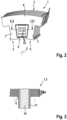
- Fig.2 shows a partial view of the stator after Fig.1 in an unfinished state in which the stator laminations 4 are still loosely arranged on top of one another and all lamination teeth 7 of each individual stator tooth 5 of the stator laminated core 3 are arranged in alignment with one another, as shown in the sectional view according to Fig.3 recognizable.
- the Fig.3 shows a sectional view according to a section through the unfinished stator laminated core 3 along the section line III-III in Fig.2 .
- the stator 1 further comprises electrical conductor elements 10, which extend through the stator slots 6 of the stator core 3 and are provided for forming an electrical winding, for example, a plug-in winding.
- the conductor elements 10 each have a square, in particular rectangular, cross-section and are designed, for example, as so-called hairpins or so-called I-pins.
- a slot insulation 11 for example a slot insulation paper, is provided for electrically insulating the conductor elements 10 from the stator laminated core 3.
- stator slots 6 provided with the conductor elements 10 have cavities 9 which, in the finished state of the stator 1, can be at least partially filled with an impregnating agent 16.
- Fig.4 shows a partial view of a first embodiment of the stator according to the invention according to Fig.1 .
- Fig.5 shows a sectional view of a section through the stator laminated core along the section line VV in Fig.4 , wherein the slot insulation 11 and one of the conductor elements 10 are additionally shown in the sectional view.
- At least one stator lamination 4 is provided in the stator laminated core 3, which lamination is rotated in the circumferential direction with respect to the stator axis 2 relative to other stator laminations 4 of the stator laminated core 3 in such a way that it protrudes into each stator slot 6 of the stator laminated core 3 with a lamination tooth section 12 of one of the lamination teeth 7 into the respective stator slot 6.
- the respective twisted stator lamination 4 protrudes in each stator slot 6 at one of the two stator teeth 5 delimiting the respective stator slot 6 with the lamination tooth section 12 into the respective stator slot 6 and at the other stator tooth 5 delimiting the respective stator slot 6 a recess 13 with a negative contour corresponding to the protruding lamination tooth section 12 is formed.
- stator laminated core 3 In the stator laminated core 3, several stator laminations 4 are rotated in the circumferential direction with respect to the stator axis 2 compared to other stator laminations 4 of the stator laminated core 3, for example in the same direction of rotation.
- the plurality of twisted stator laminations 4 are arranged in the stator laminated core 3 in a plurality of spaced-apart groups 14 of adjacent stator laminations 4, wherein between each two groups 14 of twisted stator laminations 4 there are one or more non-twisted stator laminations 4.
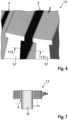
- Fig.6 shows a partial view of a stator not belonging to the invention according to Fig.1 .
- Fig.7 shows a sectional view of a section through the stator laminated core along the section line VII-VII in Fig.6 , wherein the slot insulation 11 and one of the conductor elements 10 are additionally shown in the sectional view.
- the plurality of twisted stator laminations 4 are arranged individually in the stator laminated core 3, with one or more non-twisted stator laminations 4 being located between each two twisted stator laminations 4.
- the multiple twisted stator laminations 4 of the stator core 3 are all twisted by the same angle of rotation.
- the multiple twisted stator laminations 4 of the stator core 3 can alternatively each be twisted by a different angle of rotation that increases in the axial direction relative to the stator axis 2.
- At least one stator lamination 4, for example a plurality of stator laminations 4, of the stator laminated core 3 is rotated in the circumferential direction with respect to the stator axis 2 relative to other stator laminations 4 of the stator laminated core 3 in such a way that it protrudes into each stator slot 6 of the stator laminated core 3 with a lamination tooth section 12 of one of the lamination teeth 7 into the respective stator slot 6.
Landscapes
- Engineering & Computer Science (AREA)
- Power Engineering (AREA)
- Manufacturing & Machinery (AREA)
- Iron Core Of Rotating Electric Machines (AREA)
Description
- Die Erfindung geht aus von einem Stator einer elektrischen Maschine nach der Gattung des Anspruchs 1.
- Es ist schon ein Stator einer elektrischen Maschine aus der
US2012256512 A1 bekannt, mit einem eine Statorachse aufweisenden Statorblechpaket, das eine Vielzahl von Statorzähnen und eine Vielzahl von zwischen den Statorzähnen gebildeten Statornuten umfasst und durch eine Vielzahl von gestapelten Statorlamellen gebildet ist, und mit elektrischen Leiterelementen, die durch die Statornuten des Statorblechpakets verlaufen und zur Bildung einer elektrischen Wicklung, insbesondere einer Steckwicklung, vorgesehen sind, wobei in den Statornuten jeweils eine Nutisolation, insbesondere ein Nutisolationspapier, zur elektrischen Isolation der Leiterelemente gegenüber dem Statorblechpaket vorgesehen ist, wobei die Statorlamellen jeweils eine Vielzahl von Lamellenzähnen und jeweils ein die Lamellenzähne verbindendes Lamellenjoch aufweisen, wobei die Statorzähne des Statorblechpakets jeweils durch gestapelte Lamellenzähne der Statorlamellen gebildet sind. - In den Statornuten stellt sich jeweils ein Spalt zwischen den Leiterelementen und dem Statorblechpaket bzw. zwischen den Leiterelementen und der jeweiligen Nutisolation ein, der u.a. abhängig ist von der Herstelltoleranz der Breite der Statornuten und der Herstelltoleranz der Breite der Leiterelemente. Dieser Spalt, der ein Luftspalt ist, ggf. gefüllt mit einem Imprägniermittel, verschlechtert den Wärmeübergang von den Leiterelementen auf das Statorblechpaket.
- Die Merkmale des Oberbegriffs von Anspruch 1 gehen aus der
WO 2019 142 663 A1 hervor. - Der erfindungsgemäße Stator der elektrischen Maschine mit den kennzeichnenden Merkmalen des Hauptanspruchs hat demgegenüber den Vorteil, dass der Wärmeübergang von den Leiterelementen auf das Statorblechpaket und damit die Kühlung der elektrischen Wicklung verbessert wird. Infolgedessen kann die Leistung der elektrischen Maschine erhöht werden. Darüber hinaus wird auch die mechanische Fixierung der Leiterelemente in der Statornut verbessert, so dass in der Statornut eine Imprägnierung der Leiterelemente entfallen könnte. Weiterhin können die Herstelltoleranzen für die Statorlamellen und für die Leiterelemente aufgeweitet werden, so dass sich die Herstellkosten für den Stator verringern.
- Diese Vorteile werden durch einen Stator gemäss Anspruch 1 erreicht. Es ist erfindungsgemäss im Statorblechpaket zumindest eine Statorlamelle vorgeshen, die in Umfangsrichtung bezüglich der Statorachse gegenüber anderen der Statorlamellen des Statorblechpakets derart verdreht ist, dass sie in jeder Statornut des Statorblechpakets mit einem Lamellenzahnabschnitt eines der Lamellenzähne in die jeweilige Statornut vorsteht. Durch die vorstehenden Lamellenzahnabschnitte werden in den Statornuten vorstehende Rippen gebildet, die gar keinen oder nur noch einen kleinen Spalt zu den Leiterelementen aufweisen.
- Durch die in den Unteransprüchen aufgeführten Maßnahmen sind vorteilhafte Weiterbildungen und Verbesserungen des im Hauptanspruch angegebenen Stators möglich.
- Vorteilhaft ist, dass die jeweilige verdrehte Statorlamelle in jeder Statornut jeweils an einem der beiden die jeweilige Statornut begrenzenden Statorzähne mit dem Lamellenzahnabschnitt in die jeweilige Statornut vorsteht und dass an dem anderen die jeweilige Statornut begrenzenden Statorzahn eine Vertiefung mit einer dem vorstehenden Lamellenzahnabschnitt entsprechenden Negativkontur gebildet ist.
- Erfindungsgemäss vorgesehen ist, dass im Statorblechpaket mehrere Statorlamellen in Umfangsrichtung bezüglich der Statorachse gegenüber anderen der Statorlamellen des Statorblechpakets verdreht sind, nämlich in die gleiche Verdrehrichtung. Auf diese Weise werden der Wärmeübergang von den Leiterelementen auf das Statorblechpaket und auch die mechanische Fixierung der Leiterelemente in der jeweiligen Statornut noch weiter verbessert.
- Weiterhin erfindungsgemäss vorgesehen ist, dass die mehreren verdrehten Statorlamellen im Statorblechpaket in mehreren voneinander beabstandeten Gruppen von aneinanderliegenden Statorlamellen angeordnet sind, wobei zwischen zwei Gruppen von verdrehten Statorlamellen jeweils eine oder mehrere nicht verdrehte Statorlamellen liegen.
- Nach einem ersten Ausführungsbeispiel sind die mehreren verdrehten Statorlamellen im Statorblechpaket in mehreren, voneinander beabstandeten Gruppen von aneinanderliegenden Statorlamellen angeordnet, wobei zwischen zwei Gruppen von verdrehten Statorlamellen jeweils eine oder mehrere nicht verdrehte Statorlamellen liegen.
- Nach einem zweiten Ausführungsbeispiel sind die mehreren verdrehten Statorlamellen im Statorblechpaket vereinzelt angeordnet, wobei zwischen zwei verdrehten Statorlamellen jeweils eine oder mehrere nicht verdrehte Statorlamellen liegen.
- Auch erfindungsgemäss vorgesehen ist, dass die mehreren verdrehten Statorlamellen des Statorblechpakets alle um denselben Verdrehwinkel verdreht sind. Auf diese Weise wird entweder ein ungeschrägter Stator erreicht.
- Des Weiteren vorteilhaft ist, wenn die mit den Leiterelementen versehenen Statornuten Hohlräume aufweisen, die zumindest teilweise mit einem Imprägniermittel befüllt sind.
- Darüber hinaus vorteilhaft ist, wenn die Statorlamellen des Statorblechpaketes miteinander gefügt, insbesondere verschweißt, sind und/oder am Außenumfang mit einem Statorgehäuse der elektrischen Maschine einen Pressverband bilden, und/oder in axialer Richtung bezüglich der Statorachse zwischen zwei Lagerschilden der elektrischen Maschine eingespannt sind. Auf diese Weise werden die Statorlamellen des Statorblechpaketes in ihrer Lage fixiert.
- In einem nicht zur beanspruchten Erfindung gehörenden Verfahren zur Herstellung des Stators oder der elektrischen Maschine ist vorgesehen, dass nach dem Einführen der Leiterelemente und vor dem Fixieren der Statorlamellen zumindest eine Statorlamelle des Statorblechpakets in Umfangsrichtung bezüglich der Statorachse gegenüber anderen der Statorlamellen des Statorblechpakets derart verdreht wird, dass diese in jeder Statornut des Statorblechpakets mit einem Lamellenzahnabschnitt eines der Lamellenzähne in die jeweilige Statornut vorsteht.
- Zwei Ausführungsbeispiele der Erfindung sind in der Zeichnung vereinfacht dargestellt und in der nachfolgenden Beschreibung näher erläutert.
- Fig.1
- zeigt einen Stator einer elektrischen Maschine,
- Fig.2
- eine Teilansicht des Stators nach
Fig.1 in einem unfertigen Zustand, - Fig.3
- eine Schnittansicht eines Schnitts durch das unfertige Statorblechpaket entlang der Schnittlinie III-III in
Fig.2 , - Fig.4
- eine Teilansicht eines ersten Ausführungsbeispiels des erfindungsgemäßen Stators nach
Fig.1 , - Fig.5
- eine Schnittansicht eines Schnitts durch das Statorblechpaket entlang der Schnittlinie V-V nach
Fig.4 , - Fig.6
- eine Teilansicht eines nicht zur Erfindung gehörenden Stators nach
Fig.1 und - Fig.7
- eine Schnittansicht eines Schnitts durch das Statorblechpaket entlang der Schnittlinie VII-VII nach
Fig.6 . -
Fig.1 zeigt einen Stator. - Der Stator 1 einer elektrischen Maschine umfasst zumindest ein Statorblechpaket 3, das aus einem Stapel von Statorlamellen 4 gebildet ist und eine Statorachse 2 hat. Der Stator 1 bzw. das Statorblechpaket 3 weist eine Vielzahl von Statorzähnen 5 und eine Vielzahl von zwischen den Statorzähnen 5 angeordneten Statornuten 6 auf. Dabei sind die Statornuten 6 jeweils zwischen zwei Statorzähnen 5 gebildet.
- Die Statorlamellen 4 weisen jeweils eine Vielzahl von Lamellenzähnen 7 und jeweils ein Lamellenjoch 8 auf, das die Lamellenzähne 7 miteinander verbindet. Die Statorzähne 5 des Statorblechpakets 3 werden jeweils durch gestapelte Lamellenzähne 7 der Statorlamellen 4 gebildet.
-
Fig.2 zeigt eine Teilansicht des Stators nachFig.1 in einem unfertigen Zustand, in dem die Statorlamellen 4 noch lose aufeinanderliegen und alle Lamellenzähne 7 eines jeden einzelnen Statorzahns 5 des Statorblechpakets 3 zueinander fluchtend angeordnet sind, wie in der Schnittansicht nachFig.3 erkennbar. - Die
Fig.3 zeigt eine Schnittansicht gemäß einem Schnitt durch das unfertige Statorblechpaket 3 entlang der Schnittlinie III-III inFig.2 . - Der Stator 1 umfasst weiterhin elektrische Leiterelemente 10, die durch die Statornuten 6 des Statorblechpakets 3 verlaufen und zur Bildung einer elektrischen Wicklung, beispielsweise einer Steckwicklung, vorgesehen sind. Die Leiterelemente 10 haben beispielsweise jeweils einen viereckigen, insbesondere rechteckigen, Querschnitt und sind beispielsweise als sogenannte Hairpins oder als sogenannte I-Pins ausgeführt.
- In den Statornuten 6 ist beispielsweise jeweils eine Nutisolation 11, beispielsweise ein Nutisolationspapier, zur elektrischen Isolation der Leiterelemente 10 gegenüber dem Statorblechpaket 3 vorgesehen.
- Die mit den Leiterelementen 10 versehenen Statornuten 6 weisen Hohlräume 9 auf, die im fertigen Zustand des Stators 1 zumindest teilweise mit einem Imprägniermittel 16 befüllt sein können.
-
Fig.4 zeigt eine Teilansicht eines ersten Ausführungsbeispiels des erfindungsgemäßen Stators nachFig.1 . -
Fig.5 zeigt eine Schnittansicht eines Schnitts durch das Statorblechpaket entlang der Schnittlinie V-V inFig.4 , wobei in der Schnittansicht ergänzend die Nutisolation 11 und eines der Leiterelemente 10 gezeigt ist. - Erfindungsgemäß ist vorgesehen, dass im Statorblechpaket 3 zumindest eine Statorlamelle 4 vorgesehen ist, die in Umfangsrichtung bezüglich der Statorachse 2 gegenüber anderen der Statorlamellen 4 des Statorblechpakets 3 derart verdreht ist, dass sie in jeder Statornut 6 des Statorblechpakets 3 mit einem Lamellenzahnabschnitt 12 eines der Lamellenzähne 7 in die jeweilige Statornut 6 vorsteht.
- Die jeweilige verdrehte Statorlamelle 4 steht in jeder Statornut 6 jeweils an einem der beiden die jeweilige Statornut 6 begrenzenden Statorzähne 5 mit dem Lamellenzahnabschnitt 12 in die jeweilige Statornut 6 vor und an dem anderen die jeweilige Statornut 6 begrenzenden Statorzahn 5 ist eine Vertiefung 13 mit einer dem vorstehenden Lamellenzahnabschnitt 12 entsprechenden Negativkontur gebildet.
- Gemäß den
Fig.4 bis Fig.7 sind im Statorblechpaket 3 mehrere Statorlamellen 4 in Umfangsrichtung bezüglich der Statorachse 2 gegenüber anderen der Statorlamellen 4 des Statorblechpakets 3 verdreht, beispielsweise in die gleiche Verdrehrichtung. - Nach dem ersten Ausführungsbeispiel nach
Fig.4 und Fig.5 sind die mehreren verdrehten Statorlamellen 4 im Statorblechpaket 3 in mehreren voneinander beabstandeten Gruppen 14 von aneinanderliegenden Statorlamellen 4 angeordnet, wobei zwischen zwei Gruppen 14 von verdrehten Statorlamellen 4 jeweils eine oder mehrere nicht verdrehte Statorlamellen 4 liegen. -
Fig.6 zeigt eine Teilansicht eines nicht zur Erfindung gehörenden Stators nachFig.1 . -
Fig.7 zeigt eine Schnittansicht eines Schnitts durch das Statorblechpaket entlang der Schnittlinie VII-VII inFig.6 , wobei in der Schnittansicht ergänzend die Nutisolation 11 und eines der Leiterelemente 10 gezeigt ist. - Es sind die mehreren verdrehten Statorlamellen 4 im Statorblechpaket 3 vereinzelt angeordnet, wobei zwischen zwei verdrehten Statorlamellen 4 jeweils eine oder mehrere nicht verdrehte Statorlamellen 4 liegen.
- Die mehreren verdrehten Statorlamellen 4 des Statorblechpakets 3 sind beispielsweise alle um denselben Verdrehwinkel verdreht. Zur Erzielung eines geschrägten Stators 1 können die mehreren verdrehten Statorlamellen 4 des Statorblechpakets 3 alternativ auch jeweils um einen unterschiedlichen, in axialer Richtung bezüglich der Statorachse 2 zunehmenden Verdrehwinkel verdreht sein.
- Zur Herstellung eines nicht zur Erfindung gehörenden Stators 1 werden die folgenden Schritte durchgeführt:
- a. Stapeln der Statorlamellen 4 zu einem Statorblechpaket 3,
- b. Optional Einführen der Nutisolation 11 in die Statornuten 6,
- c. Einführen der Leiterelemente 10 in die jeweiligen Statornuten 6,
- d. Fixieren der Statorlamellen 4 des Statorblechpakets 3, beispielsweise Fügen, insbesondere Verschweißen der Statorlamellen 4.
- Es wird zeitlich betrachtet nach dem Einführen der Leiterelemente 10 (Schritt c) und vor dem Fixieren der Statorlamellen 4 (Schritt d) zumindest eine Statorlamelle 4, beispielsweise mehrere Statorlamellen 4, des Statorblechpakets 3 in Umfangsrichtung bezüglich der Statorachse 2 gegenüber anderen der Statorlamellen 4 des Statorblechpakets 3 derart verdreht, dass diese in jeder Statornut 6 des Statorblechpakets 3 mit einem Lamellenzahnabschnitt 12 eines der Lamellenzähne 7 in die jeweilige Statornut 6 vorsteht.
Claims (5)
- Stator einer elektrischen Maschine mit einem eine Statorachse (2) aufweisenden Statorblechpaket (3), das eine Vielzahl von Statorzähnen (5) und eine Vielzahl von zwischen den Statorzähnen (5) gebildeten Statornuten (6) umfasst und durch eine Vielzahl von gestapelten Statorlamellen (4) gebildet ist, und mit elektrischen Leiterelementen (10), die durch die Statornuten (6) des Statorblechpakets (3) verlaufen und zur Bildung einer elektrischen Wicklung, insbesondere einer Steckwicklung, vorgesehen sind, wobei in den Statornuten (6) jeweils eine Nutisolation (11), insbesondere ein Nutisolationspapier, zur elektrischen Isolation der Leiterelemente (10) gegenüber dem Statorblechpaket (3) vorgesehen ist, wobei die Statorlamellen (4) jeweils eine Vielzahl von Lamellenzähnen (7) und jeweils ein die Lamellenzähne (7) verbindendes Lamellenjoch (8) aufweisen, wobei die Statorzähne (5) des Statorblechpakets (3) jeweils durch gestapelte Lamellenzähne (7) der Statorlamellen (4) gebildet sind, wobei im Statorblechpaket (3) mehrere Statorlamellen (4) vorgesehen sind, die in Umfangsrichtung bezüglich der Statorachse (2) gegenüber anderen der Statorlamellen (4) des Statorblechpakets (3) derart in die gleiche Verdrehrichtung verdreht sind, dass sie in jeder Statornut (6) des Statorblechpakets (3) jeweils mit einem Lamellenzahnabschnitt (12) eines der Lamellenzähne (7) in die jeweilige Statornut (6) vorstehen, wobei die mehreren verdrehten Statorlamellen (4) im Statorblechpaket (3) in mehreren voneinander beabstandeten Gruppen (14) von aneinanderliegenden Statorlamellen (4) angeordnet sind, wobei zwischen zwei Gruppen (14) von verdrehten Statorlamellen (4) jeweils eine oder mehrere nicht verdrehte Statorlamellen (4) liegen,
dadurch gekennzeichnet, dass
die mehreren verdrehten Statorlamellen (4) des Statorblechpakets (3) alle um denselben Verdrehwinkel verdreht sind. - Stator nach Anspruch 1, dadurch gekennzeichnet, dass die jeweilige verdrehte Statorlamelle (4) in jeder Statornut (6) jeweils an einem der beiden die jeweilige Statornut (6) begrenzenden Statorzähne (5) mit dem Lamellenzahnabschnitt (12) in die jeweilige Statornut (6) vorsteht und dass an dem anderen die jeweilige Statornut (6) begrenzenden Statorzahn (5) eine Vertiefung (13) mit einer dem vorstehenden Lamellenzahnabschnitt (12) entsprechenden Negativkontur gebildet ist.
- Stator nach einem der vorhergehenden Ansprüche, dadurch gekennzeichnet, dass die mit den Leiterelementen (10) versehenen Statornuten (6) Hohlräume (9) aufweisen, die zumindest teilweise mit einem Imprägniermittel (16) befüllt sind.
- Stator nach einem der vorhergehenden Ansprüche, dadurch gekennzeichnet, dass die Leiterelemente (10) jeweils einen viereckigen, insbesondere rechteckigen, Querschnitt aufweisen und als Hairpin oder als I-Pin ausgebildet sind.
- Elektrische Maschine mit einem Stator nach einem der vorhergehenden Ansprüche, dadurch gekennzeichnet, dass die Statorlamellen (4) des Statorblechpaketes (3) miteinander gefügt, insbesondere verschweißt, sind und/oder am Außenumfang mit einem Statorgehäuse (20) einen Pressverband bilden, und/oder in axialer Richtung bezüglich der Statorachse (2) zwischen zwei Lagerschilden des Statorgehäuses (20) eingespannt sind.
Applications Claiming Priority (2)
| Application Number | Priority Date | Filing Date | Title |
|---|---|---|---|
| DE102020205448.7A DE102020205448A1 (de) | 2020-04-29 | 2020-04-29 | Stator einer elektrischen Maschine |
| PCT/EP2021/057218 WO2021219293A1 (de) | 2020-04-29 | 2021-03-22 | Stator einer elektrischen maschine |
Publications (2)
| Publication Number | Publication Date |
|---|---|
| EP4143949A1 EP4143949A1 (de) | 2023-03-08 |
| EP4143949B1 true EP4143949B1 (de) | 2025-06-11 |
Family
ID=75277994
Family Applications (1)
| Application Number | Title | Priority Date | Filing Date |
|---|---|---|---|
| EP21715181.0A Active EP4143949B1 (de) | 2020-04-29 | 2021-03-22 | Stator einer elektrischen maschine |
Country Status (5)
| Country | Link |
|---|---|
| US (1) | US12244176B2 (de) |
| EP (1) | EP4143949B1 (de) |
| CN (1) | CN115398775A (de) |
| DE (1) | DE102020205448A1 (de) |
| WO (1) | WO2021219293A1 (de) |
Families Citing this family (5)
| Publication number | Priority date | Publication date | Assignee | Title |
|---|---|---|---|---|
| DE102020205448A1 (de) * | 2020-04-29 | 2021-11-04 | Robert Bosch Gesellschaft mit beschränkter Haftung | Stator einer elektrischen Maschine |
| DE102021200844A1 (de) | 2021-01-29 | 2022-08-04 | Siemens Mobility GmbH | Verfahren zum Formen und Einbringen von Spulen in einen Stator einer elektrischen rotierenden Maschine |
| JP7512955B2 (ja) * | 2021-06-02 | 2024-07-09 | トヨタ自動車株式会社 | ステータとその製造方法 |
| DE102024206737A1 (de) * | 2024-07-18 | 2026-01-22 | Robert Bosch Gesellschaft mit beschränkter Haftung | Stator einer elektrischen Maschine |
| US20260055687A1 (en) * | 2024-08-20 | 2026-02-26 | Halliburton Energy Services, Inc. | Enhanced cooling of non-encapsulated motor stators for electrical submersible pumps |
Family Cites Families (17)
| Publication number | Priority date | Publication date | Assignee | Title |
|---|---|---|---|---|
| DE2912592A1 (de) * | 1979-03-28 | 1980-10-09 | Siemens Ag | Elektrische maschine mit lamelliertem blechpaket |
| FR2494926A1 (fr) * | 1980-11-24 | 1982-05-28 | Marchal Equip Auto | Procede de fabrication de stator ou rotor annulaire comportant des dents polaires exterieures |
| JP5470015B2 (ja) * | 2009-12-04 | 2014-04-16 | 株式会社日立製作所 | 回転電機 |
| EP2518865A4 (de) | 2009-12-23 | 2015-12-09 | Toyota Motor Co Ltd | Statorkonstruktion für eine elektrische maschine und verfahren zur statormontage |
| DE102012224153A1 (de) * | 2012-12-21 | 2014-06-26 | Robert Bosch Gmbh | Stator für eine elektrische Maschine |
| JP2015142428A (ja) * | 2014-01-28 | 2015-08-03 | トヨタ自動車株式会社 | ステータ |
| EP3048705A1 (de) * | 2015-01-21 | 2016-07-27 | Siemens Aktiengesellschaft | Elektrische rotierende Maschine mit durch Fasergewebe versteiftem Blechpaket |
| FR3045235B1 (fr) * | 2015-12-11 | 2019-04-26 | Moteurs Leroy-Somer | Machine électrique tournante comportant un stator avec un paquet de tôles magné- tiques et un carter, permettant l'amélioration de l'efficacité du refroidissement |
| DE102016208692A1 (de) * | 2016-05-20 | 2017-11-23 | Zf Friedrichshafen Ag | Rotor einer elektrischen Maschine mit einem Blechpaket |
| DE102017102255A1 (de) * | 2017-02-06 | 2018-08-09 | Ebm-Papst Mulfingen Gmbh & Co. Kg | Stator für einen Elektromotor |
| JP2018164374A (ja) * | 2017-03-27 | 2018-10-18 | 本田技研工業株式会社 | 回転電機用コアユニットおよび回転電機 |
| US10923972B2 (en) * | 2017-12-01 | 2021-02-16 | American Axle & Manufacturing, Inc. | Electric motor having stator with laminations configured to form distinct cooling channels |
| JP7028261B2 (ja) * | 2018-01-18 | 2022-03-02 | 株式会社アイシン | ステータの製造方法およびステータ |
| GB201916070D0 (en) * | 2019-11-05 | 2019-12-18 | Cummins Generator Technologies | Stator for a rotating electrical machine |
| DE102020205448A1 (de) * | 2020-04-29 | 2021-11-04 | Robert Bosch Gesellschaft mit beschränkter Haftung | Stator einer elektrischen Maschine |
| DE102021107454B4 (de) * | 2021-03-25 | 2023-02-02 | Dr. Ing. H.C. F. Porsche Aktiengesellschaft | Statoreinrichtung für eine elektrische Maschine und Verfahren zur Herstellung |
| DE102021203168A1 (de) * | 2021-03-30 | 2022-10-06 | Robert Bosch Gesellschaft mit beschränkter Haftung | Stator einer elektrischen Maschine |
-
2020
- 2020-04-29 DE DE102020205448.7A patent/DE102020205448A1/de active Pending
-
2021
- 2021-03-22 US US17/922,136 patent/US12244176B2/en active Active
- 2021-03-22 CN CN202180031883.0A patent/CN115398775A/zh active Pending
- 2021-03-22 WO PCT/EP2021/057218 patent/WO2021219293A1/de not_active Ceased
- 2021-03-22 EP EP21715181.0A patent/EP4143949B1/de active Active
Also Published As
| Publication number | Publication date |
|---|---|
| CN115398775A (zh) | 2022-11-25 |
| US20230179036A1 (en) | 2023-06-08 |
| US12244176B2 (en) | 2025-03-04 |
| WO2021219293A1 (de) | 2021-11-04 |
| DE102020205448A1 (de) | 2021-11-04 |
| EP4143949A1 (de) | 2023-03-08 |
Similar Documents
| Publication | Publication Date | Title |
|---|---|---|
| EP1114500B1 (de) | Elektromotor | |
| EP4143949A1 (de) | Stator einer elektrischen maschine | |
| EP2647109B1 (de) | Verfahren zur herstellung einer ständerwicklung einer elektrischen maschine, insbesondere zur herstellung eines wechselstromgenerators | |
| DE102021204202A1 (de) | Stator einer elektrischen Maschine | |
| DE102019215015A1 (de) | Transversalflussmaschine | |
| DE102018118465A1 (de) | Stator für eine rotierende elektrische Maschine | |
| DE102012100332A1 (de) | Stator für eine rotierende elektrische Maschine und Verfahren zu seiner Herstellung | |
| DE102021202678A1 (de) | Verfahren zum Herstellen eines Stators, sowie ein Stator und eine elektrische Maschine aufweisend einen solchen | |
| DE102015220112A1 (de) | Elektrische Maschine umfassend einen Stator mit reduziertem Wicklungsüberhang | |
| DE102020204576A1 (de) | Lamellenpaket für eine elektrische Maschine, sowie eine elektrische Maschine aufweisend ein Lamellenpaket, und Verfahren zum Herstellen eines Statorgrundkörpers | |
| EP3216113B1 (de) | Rotor oder stator mit gestecktem flachem wickelkopf | |
| DE102017102255A1 (de) | Stator für einen Elektromotor | |
| DE102018205258A1 (de) | Elektrische Maschine | |
| DE102015200159B4 (de) | Rotierende elektrische Maschine mit Permanentmagneten | |
| DE102021203168A1 (de) | Stator einer elektrischen Maschine | |
| DE102021200809A1 (de) | Eine Rotorlamelle, ein Rotorblechpaket, ein Rotor und ein Verfahren zum Fertigen eines Rotors | |
| DE102020215608A1 (de) | Verfahren zum Herstellen einer Verschaltungsanordnung sowie eine elektrische Maschine | |
| DE102021112931A1 (de) | Stator einer elektrischen Maschine, Verfahren zum Herstellen desselben und elektrische Maschine | |
| WO2019166157A1 (de) | Spulenwicklung für einen stator einer rotierenden elektrischen maschine | |
| DE102014213435A1 (de) | Verfahren zum Herstellen einer elektrischen Maschine mit Formspulen sowie elektrische Maschine und Herstellungswerkzeug | |
| WO2024114996A1 (de) | Rotor einer elektrischen maschine | |
| DE102018215548A1 (de) | Rotor einer elektrischen Maschine | |
| DE102018128185A1 (de) | Elektromotor mit einem mehrteiligen Statorpaket | |
| EP3618232A1 (de) | Elektrische maschine, verfahren zur herstellung einer elektrischen maschine und elektrisches fahrzeug | |
| WO2009016196A1 (de) | Elektrische maschine |
Legal Events
| Date | Code | Title | Description |
|---|---|---|---|
| STAA | Information on the status of an ep patent application or granted ep patent |
Free format text: STATUS: UNKNOWN |
|
| STAA | Information on the status of an ep patent application or granted ep patent |
Free format text: STATUS: THE INTERNATIONAL PUBLICATION HAS BEEN MADE |
|
| PUAI | Public reference made under article 153(3) epc to a published international application that has entered the european phase |
Free format text: ORIGINAL CODE: 0009012 |
|
| STAA | Information on the status of an ep patent application or granted ep patent |
Free format text: STATUS: REQUEST FOR EXAMINATION WAS MADE |
|
| 17P | Request for examination filed |
Effective date: 20221129 |
|
| AK | Designated contracting states |
Kind code of ref document: A1 Designated state(s): AL AT BE BG CH CY CZ DE DK EE ES FI FR GB GR HR HU IE IS IT LI LT LU LV MC MK MT NL NO PL PT RO RS SE SI SK SM TR |
|
| DAV | Request for validation of the european patent (deleted) | ||
| DAX | Request for extension of the european patent (deleted) | ||
| GRAP | Despatch of communication of intention to grant a patent |
Free format text: ORIGINAL CODE: EPIDOSNIGR1 |
|
| STAA | Information on the status of an ep patent application or granted ep patent |
Free format text: STATUS: GRANT OF PATENT IS INTENDED |
|
| INTG | Intention to grant announced |
Effective date: 20250311 |
|
| GRAS | Grant fee paid |
Free format text: ORIGINAL CODE: EPIDOSNIGR3 |
|
| GRAA | (expected) grant |
Free format text: ORIGINAL CODE: 0009210 |
|
| STAA | Information on the status of an ep patent application or granted ep patent |
Free format text: STATUS: THE PATENT HAS BEEN GRANTED |
|
| AK | Designated contracting states |
Kind code of ref document: B1 Designated state(s): AL AT BE BG CH CY CZ DE DK EE ES FI FR GB GR HR HU IE IS IT LI LT LU LV MC MK MT NL NO PL PT RO RS SE SI SK SM TR |
|
| REG | Reference to a national code |
Ref country code: GB Ref legal event code: FG4D Free format text: NOT ENGLISH |
|
| REG | Reference to a national code |
Ref country code: CH Ref legal event code: EP |
|
| REG | Reference to a national code |
Ref country code: DE Ref legal event code: R096 Ref document number: 502021007709 Country of ref document: DE |
|
| REG | Reference to a national code |
Ref country code: IE Ref legal event code: FG4D Free format text: LANGUAGE OF EP DOCUMENT: GERMAN |
|
| PG25 | Lapsed in a contracting state [announced via postgrant information from national office to epo] |
Ref country code: FI Free format text: LAPSE BECAUSE OF FAILURE TO SUBMIT A TRANSLATION OF THE DESCRIPTION OR TO PAY THE FEE WITHIN THE PRESCRIBED TIME-LIMIT Effective date: 20250611 Ref country code: ES Free format text: LAPSE BECAUSE OF FAILURE TO SUBMIT A TRANSLATION OF THE DESCRIPTION OR TO PAY THE FEE WITHIN THE PRESCRIBED TIME-LIMIT Effective date: 20250611 |
|
| REG | Reference to a national code |
Ref country code: LT Ref legal event code: MG9D |
|
| PG25 | Lapsed in a contracting state [announced via postgrant information from national office to epo] |
Ref country code: GR Free format text: LAPSE BECAUSE OF FAILURE TO SUBMIT A TRANSLATION OF THE DESCRIPTION OR TO PAY THE FEE WITHIN THE PRESCRIBED TIME-LIMIT Effective date: 20250912 Ref country code: NO Free format text: LAPSE BECAUSE OF FAILURE TO SUBMIT A TRANSLATION OF THE DESCRIPTION OR TO PAY THE FEE WITHIN THE PRESCRIBED TIME-LIMIT Effective date: 20250911 |
|
| REG | Reference to a national code |
Ref country code: NL Ref legal event code: MP Effective date: 20250611 |
|
| PG25 | Lapsed in a contracting state [announced via postgrant information from national office to epo] |
Ref country code: BG Free format text: LAPSE BECAUSE OF FAILURE TO SUBMIT A TRANSLATION OF THE DESCRIPTION OR TO PAY THE FEE WITHIN THE PRESCRIBED TIME-LIMIT Effective date: 20250611 |
|
| PG25 | Lapsed in a contracting state [announced via postgrant information from national office to epo] |
Ref country code: HR Free format text: LAPSE BECAUSE OF FAILURE TO SUBMIT A TRANSLATION OF THE DESCRIPTION OR TO PAY THE FEE WITHIN THE PRESCRIBED TIME-LIMIT Effective date: 20250611 |
|
| PG25 | Lapsed in a contracting state [announced via postgrant information from national office to epo] |
Ref country code: RS Free format text: LAPSE BECAUSE OF FAILURE TO SUBMIT A TRANSLATION OF THE DESCRIPTION OR TO PAY THE FEE WITHIN THE PRESCRIBED TIME-LIMIT Effective date: 20250911 |
|
| PG25 | Lapsed in a contracting state [announced via postgrant information from national office to epo] |
Ref country code: LV Free format text: LAPSE BECAUSE OF FAILURE TO SUBMIT A TRANSLATION OF THE DESCRIPTION OR TO PAY THE FEE WITHIN THE PRESCRIBED TIME-LIMIT Effective date: 20250611 |
|
| PG25 | Lapsed in a contracting state [announced via postgrant information from national office to epo] |
Ref country code: NL Free format text: LAPSE BECAUSE OF FAILURE TO SUBMIT A TRANSLATION OF THE DESCRIPTION OR TO PAY THE FEE WITHIN THE PRESCRIBED TIME-LIMIT Effective date: 20250611 |
|
| PG25 | Lapsed in a contracting state [announced via postgrant information from national office to epo] |
Ref country code: PT Free format text: LAPSE BECAUSE OF FAILURE TO SUBMIT A TRANSLATION OF THE DESCRIPTION OR TO PAY THE FEE WITHIN THE PRESCRIBED TIME-LIMIT Effective date: 20251013 |
|
| PG25 | Lapsed in a contracting state [announced via postgrant information from national office to epo] |
Ref country code: IS Free format text: LAPSE BECAUSE OF FAILURE TO SUBMIT A TRANSLATION OF THE DESCRIPTION OR TO PAY THE FEE WITHIN THE PRESCRIBED TIME-LIMIT Effective date: 20251011 |
|
| PG25 | Lapsed in a contracting state [announced via postgrant information from national office to epo] |
Ref country code: SM Free format text: LAPSE BECAUSE OF FAILURE TO SUBMIT A TRANSLATION OF THE DESCRIPTION OR TO PAY THE FEE WITHIN THE PRESCRIBED TIME-LIMIT Effective date: 20250611 |
|
| PG25 | Lapsed in a contracting state [announced via postgrant information from national office to epo] |
Ref country code: CZ Free format text: LAPSE BECAUSE OF FAILURE TO SUBMIT A TRANSLATION OF THE DESCRIPTION OR TO PAY THE FEE WITHIN THE PRESCRIBED TIME-LIMIT Effective date: 20250611 |
|
| PG25 | Lapsed in a contracting state [announced via postgrant information from national office to epo] |
Ref country code: PL Free format text: LAPSE BECAUSE OF FAILURE TO SUBMIT A TRANSLATION OF THE DESCRIPTION OR TO PAY THE FEE WITHIN THE PRESCRIBED TIME-LIMIT Effective date: 20250611 |
|
| PG25 | Lapsed in a contracting state [announced via postgrant information from national office to epo] |
Ref country code: EE Free format text: LAPSE BECAUSE OF FAILURE TO SUBMIT A TRANSLATION OF THE DESCRIPTION OR TO PAY THE FEE WITHIN THE PRESCRIBED TIME-LIMIT Effective date: 20250611 |
|
| PG25 | Lapsed in a contracting state [announced via postgrant information from national office to epo] |
Ref country code: SK Free format text: LAPSE BECAUSE OF FAILURE TO SUBMIT A TRANSLATION OF THE DESCRIPTION OR TO PAY THE FEE WITHIN THE PRESCRIBED TIME-LIMIT Effective date: 20250611 |
|
| REG | Reference to a national code |
Ref country code: DE Ref legal event code: R097 Ref document number: 502021007709 Country of ref document: DE |
|
| PG25 | Lapsed in a contracting state [announced via postgrant information from national office to epo] |
Ref country code: DK Free format text: LAPSE BECAUSE OF FAILURE TO SUBMIT A TRANSLATION OF THE DESCRIPTION OR TO PAY THE FEE WITHIN THE PRESCRIBED TIME-LIMIT Effective date: 20250611 |
|
| PLBE | No opposition filed within time limit |
Free format text: ORIGINAL CODE: 0009261 |
|
| STAA | Information on the status of an ep patent application or granted ep patent |
Free format text: STATUS: NO OPPOSITION FILED WITHIN TIME LIMIT |
|
| PGFP | Annual fee paid to national office [announced via postgrant information from national office to epo] |
Ref country code: FR Payment date: 20260324 Year of fee payment: 6 |
|
| REG | Reference to a national code |
Ref country code: CH Ref legal event code: L10 Free format text: ST27 STATUS EVENT CODE: U-0-0-L10-L00 (AS PROVIDED BY THE NATIONAL OFFICE) Effective date: 20260423 |