EP4142164A1 - Radio frequency pa mid device, radio frequency transceiving system, and communication device - Google Patents
Radio frequency pa mid device, radio frequency transceiving system, and communication device Download PDFInfo
- Publication number
- EP4142164A1 EP4142164A1 EP21812262.0A EP21812262A EP4142164A1 EP 4142164 A1 EP4142164 A1 EP 4142164A1 EP 21812262 A EP21812262 A EP 21812262A EP 4142164 A1 EP4142164 A1 EP 4142164A1
- Authority
- EP
- European Patent Office
- Prior art keywords
- radio
- frequency
- antenna
- port
- terminal
- Prior art date
- Legal status (The legal status is an assumption and is not a legal conclusion. Google has not performed a legal analysis and makes no representation as to the accuracy of the status listed.)
- Pending
Links
Images


Classifications
-
- H—ELECTRICITY
- H04—ELECTRIC COMMUNICATION TECHNIQUE
- H04L—TRANSMISSION OF DIGITAL INFORMATION, e.g. TELEGRAPHIC COMMUNICATION
- H04L5/00—Arrangements affording multiple use of the transmission path
- H04L5/14—Two-way operation using the same type of signal, i.e. duplex
-
- H—ELECTRICITY
- H04—ELECTRIC COMMUNICATION TECHNIQUE
- H04B—TRANSMISSION
- H04B1/00—Details of transmission systems, not covered by a single one of groups H04B3/00 - H04B13/00; Details of transmission systems not characterised by the medium used for transmission
- H04B1/005—Details of transmission systems, not covered by a single one of groups H04B3/00 - H04B13/00; Details of transmission systems not characterised by the medium used for transmission adapting radio receivers, transmitters andtransceivers for operation on two or more bands, i.e. frequency ranges
- H04B1/0053—Details of transmission systems, not covered by a single one of groups H04B3/00 - H04B13/00; Details of transmission systems not characterised by the medium used for transmission adapting radio receivers, transmitters andtransceivers for operation on two or more bands, i.e. frequency ranges with common antenna for more than one band
- H04B1/006—Details of transmission systems, not covered by a single one of groups H04B3/00 - H04B13/00; Details of transmission systems not characterised by the medium used for transmission adapting radio receivers, transmitters andtransceivers for operation on two or more bands, i.e. frequency ranges with common antenna for more than one band using switches for selecting the desired band
-
- H—ELECTRICITY
- H03—ELECTRONIC CIRCUITRY
- H03F—AMPLIFIERS
- H03F3/00—Amplifiers with only discharge tubes or only semiconductor devices as amplifying elements
- H03F3/20—Power amplifiers, e.g. Class B amplifiers, Class C amplifiers
- H03F3/24—Power amplifiers, e.g. Class B amplifiers, Class C amplifiers of transmitter output stages
- H03F3/245—Power amplifiers, e.g. Class B amplifiers, Class C amplifiers of transmitter output stages with semiconductor devices only
-
- H—ELECTRICITY
- H04—ELECTRIC COMMUNICATION TECHNIQUE
- H04B—TRANSMISSION
- H04B1/00—Details of transmission systems, not covered by a single one of groups H04B3/00 - H04B13/00; Details of transmission systems not characterised by the medium used for transmission
- H04B1/02—Transmitters
- H04B1/04—Circuits
-
- H—ELECTRICITY
- H04—ELECTRIC COMMUNICATION TECHNIQUE
- H04B—TRANSMISSION
- H04B1/00—Details of transmission systems, not covered by a single one of groups H04B3/00 - H04B13/00; Details of transmission systems not characterised by the medium used for transmission
- H04B1/38—Transceivers, i.e. devices in which transmitter and receiver form a structural unit and in which at least one part is used for functions of transmitting and receiving
- H04B1/40—Circuits
- H04B1/44—Transmit/receive switching
-
- H—ELECTRICITY
- H03—ELECTRONIC CIRCUITRY
- H03F—AMPLIFIERS
- H03F2200/00—Indexing scheme relating to amplifiers
- H03F2200/294—Indexing scheme relating to amplifiers the amplifier being a low noise amplifier [LNA]
-
- H—ELECTRICITY
- H03—ELECTRONIC CIRCUITRY
- H03F—AMPLIFIERS
- H03F2200/00—Indexing scheme relating to amplifiers
- H03F2200/451—Indexing scheme relating to amplifiers the amplifier being a radio frequency amplifier
-
- H—ELECTRICITY
- H04—ELECTRIC COMMUNICATION TECHNIQUE
- H04B—TRANSMISSION
- H04B1/00—Details of transmission systems, not covered by a single one of groups H04B3/00 - H04B13/00; Details of transmission systems not characterised by the medium used for transmission
- H04B1/02—Transmitters
- H04B1/04—Circuits
- H04B2001/0408—Circuits with power amplifiers
Definitions
- the present disclosure relates to the field of radio-frequency technologies, and more particularly, to a radio-frequency Power Amplifier Modules including Duplexers (PA Mid) device, a radio-frequency transceiving system, and a communication apparatus.
- a radio-frequency Power Amplifier Modules including Duplexers (PA Mid) device, a radio-frequency transceiving system, and a communication apparatus.
- PA Mid Duplexers
- 5G mobile communication technology has a higher communication frequency than 4G mobile communication technology.
- a plurality of discrete switches is required to be disposed in transmitting paths of a radio-frequency system to support polling transmission of a radio-frequency signal among a plurality of antennas, thereby leading to higher cost and occupying a relatively large area of a substrate.
- a radio-frequency PA Mid device a radio-frequency transceiving system, and a communication apparatus are provided.
- the radio-frequency PA Mid device has a transmitting port configured to connect to a radio-frequency transceiver and a plurality of antenna ports each configured to connect to an antenna.
- the radio-frequency PA Mid device includes a power amplifier, a first filtering unit, and a multi-channel selection switch.
- the power amplifier has an input terminal connected to the transmitting port, and the power amplifier is configured to perform a power amplification processing on a received radio-frequency signal.
- the first filtering unit is connected to an output terminal of the power amplifier, and the first filtering unit is configured to perform a filtering processing on the received radio-frequency signal.
- the multi-channel selection switch has at least one first terminal and a plurality of second terminals.
- One of the at least one first terminal is connected to the first filtering unit, and the plurality of second terminals is connected to the plurality of antenna ports in a one-to-one correspondence.
- the multi-channel selection switch is configured to selectively switch on a transmitting path between the transmitting port and any one of the plurality of antenna ports for transmission of the radio-frequency signal and supporting a function of polling transmission of a Sounding Reference Signal (SRS) among the plurality of antenna ports.
- SRS Sounding Reference Signal
- the radio-frequency transceiving system includes an antenna group, a radio-frequency L-DRX module connected to the first antenna, and the above-mentioned radio-frequency PA Mid device.
- the antenna group at least includes a first antenna and a second antenna, and the antenna group is configured to transmit and receive a radio-frequency signal.
- the radio-frequency L-DRX module is configured to receive the radio-frequency signal inputted via the second antenna.
- One of the plurality of antenna ports of the radio-frequency PA Mid device is connected to the second antenna, and another one of the plurality of antenna ports being connected to the radio-frequency L-DRX module.
- the radio-frequency PA Mid device is configured to support a function of polling transmission of SRS between the first antenna and the second antenna.
- the communication apparatus includes a radio-frequency transceiver, and the above-mentioned radio-frequency transceiving system.
- the radio-frequency transceiving system is connected to the radio-frequency transceiver.
- the power amplifier, the first filtering unit, and the multi-channel selection switch in the radio-frequency PA Mid device are all integrated and packaged in the same chip, thereby increasing an integration level of the radio-frequency PA Mid device, while reducing the costs and an area of a substrate occupied by various components in a radio-frequency system.
- an area of at least 10 mm 2 can be saved, when compared with the case that the multi-channel selection switch is disposed outside the radio-frequency PA Mid device. In this way, more space can be saved for performance optimization of other modules.
- the radio-frequency PA Mid device integrated with the multi-channel selection switch has the same as the radio-frequency PA Mid device without the multi-channel selection switch. That is, the size of the radio-frequency PA Mid device is unchanged by integrating the multi-channel selection switch into the radio-frequency PA Mid device 10.
- first or second is only for descriptive purposes, and it cannot be indicating or implying relative importance or implicitly indicating the number of indicated technical features. Therefore, the features defined with “first” or “second” can explicitly or implicitly include at least one of the features.
- plurality of' means at least two, unless otherwise specifically indicated.
- a number of' means at least one, unless otherwise specifically indicated.
- a radio-frequency transceiving system involved in the embodiments of the present disclosure can be applied to a communication apparatus having wireless communication capabilities.
- the communication apparatus may be a handheld apparatus, a vehicle-mounted apparatus, a wearable apparatus, a computing apparatus, any other processing apparatuses connected to a wireless modem, a user equipment (UE) in various forms (e.g., a mobile phone), or a mobile station (MS), etc.
- UE user equipment
- MS mobile station
- a network device may include a base station, an access point, etc.
- a radio-frequency PA Mid device is provided. As illustrated in FIG. 1 , in an embodiment, the radio-frequency PA Mid device 10 can be used to support control of polling transmission of radio-frequency signals among a plurality of antennas. As an example, a radio-frequency PA Mid device 10 has a plurality of transmitting paths for transmitting radio-frequency signals, to support a function of polling transmission of SRS among a plurality of antenna ports.
- the radio-frequency signal may be a 5G signal, such as a 5G signal in an N41 frequency band, a radio-frequency signal in an N77 frequency band, a radio-frequency signal in an N78 frequency band, a radio-frequency signal in an N79 frequency band, etc.
- an operating frequency band of N41 ranges from 496 MHz to 2,690 MHz
- an operating frequency band of N77 ranges from 3.3 GHz to 4.2 GHz
- an operating frequency band of N78 ranges from 3.3 GHz to 3.8 GHz
- an operating frequency band of N79 ranges from 4.4 GHz to 5.0 GHz.
- the operating frequency band of N77 covers the operating frequency band of N78.
- the radio-frequency PAMid device 10 when it can support a transceiving of radio-frequency signals in the N77 frequency band, it can also support a transceiving of radio-frequency signals in the N78 frequency band.
- the radio-frequency signals may also be Long-Term Evolution (LTE) signals, Wireless Fidelity (WiFi) signals, etc.
- LTE Long-Term Evolution
- WiFi Wireless Fidelity
- the operating frequency band of the radio-frequency signals is not further limited.
- the radio-frequency PA Mid device 10 has a transmitting port RFIN and a plurality of antenna ports SRS (e.g., SRS1, SRS2, SRS3, SRS4).
- the radio-frequency PA Mid device 10 can be regarded as a packaged chip.
- the transmitting port RFIN and the antenna ports SRS provided in the radio-frequency PAMid device 10 can be regarded as radio-frequency pin terminals of the radio-frequency PA Mid device 10 for connecting to various external devices.
- the transmitting port RFIN may be used configured to connect to a radio-frequency transceiver.
- the plurality of antenna ports SRS may be used configured to connect to antennas.
- the radio-frequency PAMid device 10 includes a power amplifier 110, a first filtering unit 120, and a multi-channel selection switch 130.
- the transmitting port RFIN of the radio-frequency PA Mid device 10 is connected to the plurality of antenna ports SRS through the power amplifier 110, the first filtering unit 120, and the multi-channel selection switch 130 in sequence.
- the power amplifier 110 has an input terminal connected to the transmitting port RFIN, and the power amplifier 110 is configured to perform a power amplification processing on a received radio-frequency signal inputted via a receiving port.
- the first filtering unit 120 is connected to an output terminal of the power amplifier 110.
- the first filtering unit 120 is configured to receive the radio-frequency signal processed by the power amplifier 110 and filter the received radio-frequency signal.
- the multi-channel selection switch 130 includes at least one first terminal and a plurality of second terminals.
- One first terminal of the multi-channel selection switch 130 is connected to the first filtering unit 120.
- the plurality of second terminals is connected to the plurality of antenna ports SRS in a one-to-one correspondence.
- the multi-channel selection switch 130 is configured to selectively switch on a transmitting path between the transmitting port RFIN and any one antenna port SRS, for transmitting the radio-frequency signal and supporting a function of polling transmission of SRS among the plurality of antenna ports SRS.
- the number of the second terminals of the multi-channel selection switch 130 is the same as the number of the antenna ports SRS.
- One antenna port SRS is correspondingly connected to one second terminal of the multi-channel selection switch 130. Further, each antenna port SRS may be correspondingly connected to at least one antenna.
- the radio-frequency PA Mid device 10 may have two antenna ports SRS, which can be defined as a first antenna port SRS1 and a second antenna port SRS2.
- the first antenna port SRS1 can be connected to a first antenna
- the second antenna port SRS2 can be connected to a second antenna.
- the multi-channel selection switch 130 may be a Single-Pole Double-Throw (SPDT) switch.
- the SPDT switch has two selection terminals connected to the first antenna port SRS1 and the second antenna port SRS2, respectively, thereby achieving the polling transmission of SRS by the first antenna and the second antenna.
- the radio-frequency signal is inputted to the radio-frequency PA Mid device 10 via the transmitting port RFIN; the radio-frequency signal reaches the multi-channel selection switch 130 via the power amplifier 110 and the first filtering unit 120, switched to the first antenna port SRS 1; and the radio-frequency signal is transmitted via the first antenna. Further, the radio-frequency signal may be switched to the second antenna port SRS2 through the multi-channel selection switch 130 and transmitted via the second antenna.
- the radio-frequency PA Mid device 10 may have four antenna ports SRS, which can be defined as a first antenna port SRS1, a second antenna port SRS2, a third antenna port SRS3, and a fourth antenna port SRS4.
- the first antenna port SRS1 can be connected to a first antenna.
- the second antenna port SRS2 can be connected to a second antenna.
- the third antenna port SRS3 can be connected to a third antenna.
- the fourth antenna port SRS4 can be connected to a fourth antenna.
- the multi-channel selection switch 130 can be a Single-Pole Four-Throw (SP4T) switch.
- the SP4T switch has four selection terminals connected to the first antenna port SRS1, the second antenna port SRS2, the third antenna port SRS3, and the fourth antenna port SRS4, respectively. Through switching control of the multi-channel selection switch 130, the polling transmission of SRS by the first antenna, the second antenna, the third antenna, and the fourth antenna can be realized.
- the radio-frequency PAMid device 10 can be regarded as a packaged chip. That is, the power amplifier 10, the first filtering unit 120, and the multi-channel selection switch 130 in the radio-frequency PA Mid device 10 are all integrated and packaged in the same chip. In this way, an integration level of the radio-frequency PA Mid device 10 can be increased, the cost thereof is lowered, while reducing an area of a substrate occupied by various components in a radio-frequency system. By integrating the multi-channel selection switch 130 into the radio-frequency PA Mid device 10, an area of at least 10 mm 2 can be saved, when compared with the case that the multi-channel selection switch 130 is disposed outside the radio-frequency PA Mid device 10.
- the radio-frequency PA Mid device 10 integrated with the multi-channel selection switch 130 has the same as the radio-frequency PA Mid device 10 without the multi-channel selection switch 130. That is, the size of the radio-frequency PA Mid device 10 is unchanged by integrating the multi-channel selection switch 130 into the radio-frequency PA Mid device 10.
- the first filtering unit 120 includes a band-pass filter or a low-pass filter. It should be noted that a type of the first filtering unit 120 can be selected based on the operating frequency band of the radio-frequency signal supportable by the radio-frequency PA Mid device 10.
- the first filtering unit 120 of the radio-frequency PAMid device 10 may be a low-pass filter, which only allows radio-frequency signals in the N41 frequency band to pass through and filters out spurious waves outside of the N41 frequency band; when the radio-frequency signal supported by the radio-frequency PA Mid device 10 is a 5G signal in the N77 frequency band, the first filtering unit 120 of the radio-frequency PA Mid device 10 may be a band-pass filter, which only allows radio-frequency signals in the N77 frequency band to pass through and filters out spurious waves outside of the N77 frequency band; and when the radio-frequency signal supported by the radio-frequency PA Mid device 10 is a 5G signal in the N79 frequency band, the first filtering unit 120 of the radio-frequency PA Mid device 10 may be a band-pass filter, which only allows radio-frequency signals in the N79 frequency band to pass through and filters out spurious waves outside of the N79 frequency band.
- a suitable filter can be selected based on the frequency band of the radio-frequency signal, to perform a filtering processing on the radio-frequency signal.
- the radio-frequency PA Mid device 10 has a receiving port RXOUT configured to connect to the radio-frequency transceiver.
- the radio-frequency PAMid device 10 further includes a first switching unit 140.
- the first switching unit 140 has a control terminal connected to the first filtering unit 120, a first selection terminal connected to the output terminal of the power amplifier 110, and a second selection terminal connected to the receiving port RXOUT.
- the first switching unit 140 is configured to selectively switch on a receiving path where the receiving port RXOUT is located and the transmitting path where the transmitting port RFIN is located.
- the first switching unit 140 may be a radio-frequency SPDT switch. That is, the control terminal of the radio-frequency SPDT switch is connected to a second filtering unit 320, the first selection terminal of the radio-frequency SPDT switch is connected to the receiving port RXOUT, and the second selection terminal of the radio-frequency SPDT switch is connected to the output terminal of the power amplifier 110, to selectively switch on the receiving path and the transmitting path of the radio-frequency PAMid device 10.
- the radio-frequency PAMid device 10 can be provided with the receiving path and the transmitting path, which can perform the transceiving control of the radio-frequency signal in turn.
- the transmitting control of the radio-frequency signal can be achieved in such a manner that, the radio-frequency signal is inputted from the transmitting port RFIN, it reaches the first switching unit 140 via the power amplifier 110, it is switched to the first filtering unit 120 by the first switching unit 140 and switched to any antenna port SRS by a multi-channel switch, and the radio-frequency signal is outputted by the antenna port SRS, to achieve transmitting control of the radio-frequency signal.
- the receiving control of the radio-frequency signal can be achieved in such a manner that the radio-frequency signal is received by any antenna port SRS, it reaches the first filtering unit 120 via the multi-channel selection switch 130, and it is switched to the receiving port RXOUT by the first switching unit 140.
- the radio-frequency PA Mid device 10 has a receiving port RXOUT configured to connect to the radio-frequency transceiver and further includes a second filtering unit 150.
- the multi-channel selection switch 130 is a radio-frequency Double-Pole Four-Throw (DP4T) switch including two first terminals and four second terminals.
- the second filtering unit 150 is connected to each of the receiving port RXOUT and another first terminal of the multi-channel selection switch 130 to form a receiving path.
- the second filtering unit 150 is configured to perform a filtering processing on the radio-frequency signal received by any antenna port SRS.
- the second filtering unit 150 includes a low-pass filter or a band-pass filter. It should be noted that a type of the second filtering unit 150 can be selected based on the operating frequency band of the radio-frequency signal supportable by the radio-frequency PAMid device 10. For example, the type of filtering of the second filtering unit 150 may be the same as that of the first filtering unit 120, both of which can perform a filtering processing on the radio-frequency signal transmitted and received by the radio-frequency system.
- the first switching unit 140 is omitted and the second filtering unit 150 is added to form the receiving path for receiving the radio-frequency signal.
- the multi-channel selection switch 130 is the radio-frequency DP4T switch and has two first terminals. One first terminal of the multi-channel selection switch 130 is connected to the receiving port RXOUT via the second filtering unit 150, and the other one first terminal of the multi-channel selection switch 130 is connected to the transmitting port RFIN via the first filtering unit 120 and the power amplifier 110.
- the values of insertion loss of the radio-frequency SP4T switch are as illustrated in Table 1.
- radio-frequency cable losses for respective frequency bands are as illustrated in Table 2.
- Table 2 Values of radio-frequency cable loss of link Frequency band (GHz) N41 N77 N79 Insertion loss (dB) 2.8 2.9 2.8
- the insertion loss on a transceiving channel is reduced by removing the first switching unit 140 inside the radio-frequency PA Mid device 10.
- the first radio-frequency signal is an N41 signal and input power of the transmitting port RFIN is 28.5 dBm
- output power of the antenna port SRS is 25.9 dBm
- output powers of the antenna port SRS in N77 and N79 are as illustrated in Table 3.
- Table 3 Values of output power for the antenna port SRS Frequency band (GHz) N41 N77 N79
- the first switching unit 140 is omitted and only the multi-channel selection switch 130 is retained, which can reduce a link loss of the transceiving channel of the radio-frequency PAMid device 10. In this way, the output power of the antenna port SRS can meet communication requirements.
- the radio-frequency PA Mid device 10 when the radio-frequency PA Mid device 10 is used to support transceiving control of the radio-frequency signal in the N77 frequency band or the N97 frequency band, the radio-frequency PA Mid device 10 further includes a first low noise amplifier 160.
- the first low noise amplifier 160 is disposed in the receiving path and configured to amplify the radio-frequency signal received by any antenna port SRS.
- the radio-frequency signal is outputted via the receiving port RXOUT.
- the radio-frequency PAMid device 10 when the radio-frequency PAMid device 10 includes the first switching unit 140, the input terminal of the first low noise amplifier 160 is connected to a selection terminal of the first switching unit 140, and the output terminal of the first low noise amplifier 160 is connected to the receiving port RXOUT.
- the radio-frequency PA Mid device 10 when the radio-frequency PA Mid device 10 includes the second filtering unit 150, the input terminal of the first low noise amplifier 160 is connected to the second filtering unit 150 and the output terminal of the first low noise amplifier 160 is connected to the receiving port RXOUT.
- the radio-frequency signal can be amplified to meet communication requirements of the receiving path.
- the radio-frequency PAMid device 10 has a coupling output port CPLOUT, and the radio-frequency PA Mid device 10 further includes a coupling circuit 170.
- the coupling circuit 170 is coupled to the first filtering unit 120 and the first terminal of the multi-channel selection switch 130, and the coupling circuit 170 is connected to the coupling output port CPLOUT.
- the coupling circuit 170 is configured to couple the radio-frequency signal to output a coupling signal for measuring power information.
- the coupling signal includes a forward coupling signal and a reverse coupling signal.
- the coupling circuit 170 includes a coupling unit 171 and a coupling switch 173.
- the coupling unit 171 is configured to couple the radio-frequency signal in the transmitting path to realize a coupled output of the radio-frequency signal, which can be used to measure coupling power of the radio-frequency signal.
- the coupling unit 171 includes an input terminal a, an output terminal b, a first coupling terminal c, and a second coupling terminal d.
- the coupling unit 171 further includes a primary line extending between the input terminal a and the output terminal b and a secondary line extending between the first coupling terminal c and the second coupling terminal d.
- the input terminal a of the coupling unit 171 is coupled to the first filtering unit 120.
- the output terminal b of the coupling unit 171 is coupled to the first terminal of the multi-channel selection switch 130.
- the first coupling terminal c is configured to couple the radio-frequency signal received at the input terminal a and output a forward coupling signal.
- the second coupling terminal d is configured to couple a reflected signal of the radio-frequency signal received at the output terminal b and output a reverse coupling signal.
- Forward power information of the radio-frequency signal can be detected based on the forward coupling signal outputted at the first coupling terminal c.
- reverse power information of the radio-frequency signal can be detected based on the reverse coupling signal outputted at the second coupling terminal d.
- Such a detection mode is defined as a reverse power detection mode.
- the coupling switch 173 is connected to the first coupling terminal c, the second coupling terminal d, and the coupling output port CPLOUT.
- the coupling switch 173 is configured to selectively switch on a first coupling path between the first coupling terminal c and the coupling output port CPLOUT to detect forward power of the radio-frequency signal, in which case such a detection mode is defined as a forward power detection mode; or the coupling switch 173 is configured to selectively switch on a second coupling path between the second coupling terminal d and the coupling output port CPLOUT to detect reverse power of the radio-frequency signal, in which case such a detection mode is defined as the reverse power detection mode. That is, the coupling switch 173 is configured to switch between the forward power detection mode and the reverse power detection mode.
- the coupling unit 171 includes two directional couplers connected in reverse series.
- the radio-frequency PA Mid device 10 only has one coupling output port CPLOUT, which can meet the communication requirements.
- the complexity of radio-frequency wirings inside the radio-frequency PA Mid device 10 can be reduced, thereby improving isolation performance of the respective wirings of the radio-frequency PAMid device 10.
- the radio-frequency PA Mid device 10 may further have a coupling input port CPLIN for receiving coupling signals from other radio-frequency PAMid devices 10.
- the radio-frequency PA Mid device 10 further includes at least one control unit 180.
- the radio-frequency PAMid device 10 when the radio-frequency PA Mid device 10 supports the transceiving control of radio-frequency signals in the N41 frequency band, the radio-frequency PAMid device 10 includes one control unit 180.
- the control unit 180 is connected to the power amplifier 110, the first switching unit 140, and the coupling switch 173.
- the control unit 180 is configured to control a gain coefficient of the power amplifier 110 and control selective switching-on states of the first switching unit 140 and the coupling switch 173. Referring to FIG. 5C and FIG.
- an additional control unit 180 connected to the second low noise amplifier 350 may be provided.
- the additional control unit 180 is configured to adjust a gain coefficient of the first low noise amplifier 160 to adjust an insertion loss of a receiving link in the radio-frequency PAMid device 10.
- control unit 180 may be a Radio Frequency Front End Control Interface (RFFE) control unit 180.
- RFFE Radio Frequency Front End Control Interface
- its radio-frequency PA Mid device 10 further has an input pin CLK for clock signals, an input or bidirectional pin SDATAS for single/bidirectional data signals, a reference voltage pin VIO, etc.
- the RFFE control unit 180 may output clock and data signals to corresponding pins of the first switching unit 140 and the coupling switch 173 for on/off control of the transceiving path or the coupling path.
- the Mobile Industry Processor Interface (MIPI)-RFFE control unit 180 may output clock and data signals to the first low noise amplifier 160 to achieve gain adjustment control of the first low noise amplifier 130, or it may output the clock and data signals to the power amplifier 110 to control an operating state of the power amplifier 110.
- MIPI Mobile Industry Processor Interface
- each component included in the radio-frequency PAMid device 10 may be integrated in the same chip through a packaging process. That is, the radio-frequency PA Mid device 10 may be regarded as a packaged chip.
- the radio-frequency PA Mid device 10 When the first switching unit 140 is integrated in the radio-frequency PAMid device 10 and the radio-frequency PAMid device 10 supports radio-frequency transceiving of signals in the N41 frequency band, the radio-frequency PA Mid device 10 has a pin configuration as illustrated in FIG. 6A . The respective pins in this chip correspond to the plurality of ports provided in the radio-frequency PA Mid device 10 in a one-to-one correspondence.
- the radio-frequency PA Mid device 10 has a package structure as illustrated in FIG.
- the radio-frequency PA Mid device 10 when the radio-frequency PA Mid device 10 supports the radio-frequency transceiving of signals in the N77 or N79 frequency band, the radio-frequency PA Mid device 10 has a pin configuration as illustrated in FIG. 6C and a package structure as illustrated in FIG. 6D .
- the radio-frequency PA Mid device 10 when the second filtering unit 150 is integrated in the radio-frequency PA Mid device 10 and the radio-frequency PA Mid device 10 supports the radio-frequency transceiving in the N41 frequency band, the radio-frequency PA Mid device 10 has a pin configuration as illustrated in FIG. 7A .
- the respective pins in this chip correspond to the plurality of ports provided in the radio-frequency PA Mid device 10 in a one-to-one correspondence.
- the radio-frequency PA Mid device 10 has a package structure as illustrated in FIG. 7B , which can improve the integration level of the radio-frequency PAMid device 10.
- the radio-frequency PA Mid device 10 can support the transmitting control or transceiving control of 5G signals in the N41, N77, N79 frequency bands, etc. Accordingly, when the radio-frequency PA Mid device 10 supports the radio-frequency transceiving of signals in the N77 or N79 frequency band, the radio-frequency PA Mid device 10 has a pin configuration as illustrated in FIG. 7C and a package structure as illustrated in FIG. 7D .
- a radio-frequency transceiving system is further provided. As illustrated in FIG. 8 , in an embodiment, the radio-frequency transceiving system includes an antenna group 20, a radio-frequency L-DRX module 30, and the radio-frequency PAMid device 10 according to any of the above embodiments.
- the antenna assembly 20 at least includes a first antenna AntO and a second antenna Ant1.
- the first antenna AntO and the second antenna Ant1 can both support the radio-frequency signals in different operating frequency bands, e.g., LTE signals, WiFi signals, 5G New Radio (NR) signals, etc.
- the first antenna Ant0 can be configured to receive and transmit (i.e., transceive) radio-frequency signals in different frequency bands.
- the second antenna Ant1 can be configured to transceive radio-frequency signals in different frequency bands.
- the first antenna Ant0 and the second antenna Ant1 may be directional or non-directional antennas.
- the first antenna Ant0 and the second antenna Ant1 may be formed by any suitable type of antenna.
- the first antenna Ant0 and the second antenna Ant1 may include an antenna having a resonant element and formed by at least one of the following antenna structures: an array antenna structure, a loop antenna structure, a patch antenna structure, a slot antenna structure, a spiral antenna structure, a strip antenna, a monopole antenna, a dipole antenna, or the like.
- Different types of antennas can be used for combinations of frequency bands of different radio-frequency signals.
- the antenna assembly 20 may further include a third antenna and a fourth antenna.
- the number and type of antennas included in the antenna assembly 20 are not limited and can be determined as desired.
- the radio-frequency L-DRX module 30 is connected to the first antenna Ant0 and one antenna port SRS of the radio-frequency PA Mid device 10.
- the radio-frequency L-DRX module 30 is configured to receive the radio-frequency signal inputted by the first antenna Ant0 and transmit the radio-frequency signal outputted by the one antenna port SRS of the radio-frequency PA Mid device 10 to the first antenna Ant0, by which the radio-frequency signal is transmitted. That is, the radio-frequency L-DRX module 30 may selectively switch on another receiving path in the radio-frequency system where the radio-frequency L-DRX module 30 is located to receive the radio-frequency signal inputted from the first antenna Ant0.
- One antenna port SRS of the radio-frequency PA Mid device 10 is connected to the second antenna Ant1, and another antenna port SRS thereof is connected to the radio-frequency L-DRX module 30, to support a function of polling transmission of SRS between the first antenna Ant0 and the second antenna Ant1.
- the radio-frequency L-DRX module 30 can also switch on another transmitting path in the radio-frequency system where the radio-frequency PA Mid device 10 is located, and thus the radio-frequency signal outputted from one antenna port SRS of the radio-frequency PA Mid device 10 can be outputted via the second antenna Ant1.
- the multi-channel selection switch 130 integrated in the radio-frequency PA Mid device 10, in combination with the radio-frequency L-DRX module 30, can realize the polling transmission of the radio-frequency signal between the first antenna Ant0 and the second antenna Ant1 without providing a plurality of independent cascade switches. In this way, the costs can be lowered, and an area of the substrate occupied by different components in the radio-frequency system can be reduced.
- the radio-frequency L-DRX module 30 includes a second low noise amplifier 310, a third filtering unit 320, and a third switching unit 330.
- the second low noise amplifier 310 has an input terminal connected to the third filtering unit 320.
- the second low noise amplifier 310 is configured to amplify the received radio-frequency signal and output, via an output terminal thereof, the amplified radio-frequency signal to the radio-frequency transceiver.
- the third filtering unit 320 is connected to the third switching unit 330 and configured to perform a filtering processing on the radio-frequency signal received by the first antenna Ant0.
- the third switching unit 330 is connected to the first antenna Ant0 and one antenna port SRS of the radio-frequency PA Mid device 10.
- the third switching unit 330 is configured to selectively switch on a receiving path where the second low noise amplifier 310 is located and a transmitting path where the radio-frequency PAMid device 10 is located.
- the third switching unit 330 may be the radio-frequency SPDT switch. That is, the radio-frequency SPDT switch has the control terminal connected to the first antenna Ant0, the first selection terminal connected to the third filtering unit 320, and the second selection terminal connected to one antenna port SRS of the radio-frequency PAMid device 10, to selectively switch on the receiving path where the second low noise amplifier 310 is located and the transmitting path where the radio-frequency PAMid device 10 is located.
- the radio-frequency L-DRX module 30 when the radio-frequency L-DRX module 30 is configured to support radio-frequency signals in the N41 frequency band, the radio-frequency L-DRX module 30 further includes a bypass switch 340 in parallel with the second low noise amplifier 310.
- the bypass switch 340 may be controlled to be turned off in the event of a large blocking signal to prevent the radio-frequency signal from being received at too high power to saturate the RF transceiver.
- the second low noise amplifier 310 and the bypass switch 340 are packaged in the same chip.
- the chip may be regarded as a Low Noise Amplifier (LNA) device having the radio-frequency receiving port RXOUT and the radio-frequency antenna port ANT.
- the input terminal of the second low noise amplifier 310 is connected to the radio-frequency antenna port ANT.
- the output terminal of the second low noise amplifier 310 is connected to the radio-frequency receiving port RXOUT.
- the integration level of the LNA device can be improved by packaging the second low noise amplifier 310 and the bypass switch 340 in the same chip.
- the second low noise amplifier 310 and the third filtering unit 320 are packaged in the same chip.
- the packaged chip is regarded as the LNA device.
- the third switching unit 330 and the LNA device are two discrete devices.
- the LNA device further has the radio-frequency antenna port ANT and the radio-frequency receiving port RXOUT.
- the radio-frequency antenna port ANT is connected to the radio-frequency receiving port RXOUT via the third filtering unit 320 and the second low noise amplifier 310.
- the LNA device is further integrated with a control unit 180 configured to control the second low noise amplifier 310, to adjust the gain coefficient of the low noise amplifier. Therefore, a receiving power of the radio-frequency signal at the radio-frequency receiving port RXOUT can be adjusted.
- the second low noise amplifier 310, the third filtering unit 320, and the third switching unit 330 are all packaged in the same chip.
- the packaged chip serves as the LNA device.
- the LNA device can have the radio-frequency receiving port RXOUT, the radio-frequency transmitting port SRS, and the radio-frequency antenna port ANT.
- the control terminal of the third switching unit 330 is connected to the radio-frequency antenna port ANT.
- One selection terminal of the third switching unit 330 is connected to the third filtering unit 320.
- Another selection terminal of the third switching unit 330 is connected to one antenna port SRS of the radio-frequency PA Mid device 10 via a radio-frequency transmitting terminal.
- the third switching unit 330 is taken as the radio-frequency SPDT switch to describe the transceiving control of the radio-frequency signal of the radio-frequency L-DRX module 30.
- the radio-frequency signal received by the antenna is received via the radio-frequency antenna port ANT. That is, the radio-frequency signal enters the radio-frequency SPDT switch via the radio-frequency antenna port ANT.
- the radio-frequency SPDT switch is switched to the third filtering unit 320 to switch on the receiving path.
- the radio-frequency signal is transmitted to the radio-frequency receiving port RXOUT via the second low noise amplifier 310.
- the radio-frequency receiving port RXOUT outputs the received radio-frequency signal to the radio-frequency transceiver to complete the receiving control of the radio-frequency signal.
- the radio-frequency signal outputted by one antenna port SRS of the radio-frequency PA Mid device 10 is received by the radio-frequency transmitting port SRS. That is, the radio-frequency signal is inputted from the radio-frequency transmitting port SRS to the radio-frequency SPDT switch.
- the radio-frequency SPDT switch is switched to the radio-frequency antenna port ANT to switch on the transmitting path (also referred to as an SRS path).
- the radio-frequency signal is radiated out by the first antenna Ant0 via the radio-frequency antenna port ANT. In this way, the transmitting control of the radio-frequency signal is completed.
- the LNA device is further integrated with the control unit 180 configured to control the second low noise amplifier 310, to adjust the gain coefficient of the low noise amplifier. Therefore, the receiving power of the radio-frequency signal at the radio-frequency receiving port RXOUT can be adjusted.
- the third filtering unit 320 may be disposed at a rear end of the third switching unit 330. That is, the third filtering unit 320 is disposed between the third switching unit 330 and the radio-frequency transmitting port SRS.
- a filtering processing can be performed on the radio-frequency signal transmitted in a receiving channel and a transmitting channel, thereby improving an out-of-band rejection capability of the transmitting path.
- the transmission performance of both the transmitting path and the receiving path can be balanced.
- an integration level of the radio-frequency L-DRX module 30 can be increased, and thus resources of the substrate (e.g., a Printed Circuit Board (PCB) board) occupied by the third switching unit 330 and the third filtering unit 320.
- the radio-frequency L-DRX module 30 can have a function of controlling the transceiving of the radio-frequency signal.
- the power supply, logic control, and PCB layout and wiring of the radio-frequency L-DRX device 10 can be simplified, thereby saving the costs.
- radio-frequency L-DRX module 30 can support the transceiving control of 5G signals in the N41, N77, N79 frequency bands, etc.
- a 5G network supports beam-shaping technology, which allows directional transmission to communication apparatuses.
- a base station In order to realize the directional transmission, a base station first needs to detect a position of a communication apparatus, a quality of a transmitting path, etc., to allocate resources of the base station to each communication apparatus more accurately.
- PMI Precoding Matrix Indicator
- SRS Sounding Reference Signal
- the base station can detect a position of the terminal and a channel quality by transmitting SRS information by the communication apparatus.
- SRS antenna polling transmission is as illustrated in FIG. 13 and explained in detail below.
- 1T1R only feeding back information to the base station at the first antenna Ant0, not supporting the SRS polling transmission.
- 1T4R transmitting SRS information in turn at the first antenna Ant0 to a fourth antenna Ant3, where only one antenna is selected for transmission each time.
- NSA Non-Standalone
- 2T4R transmitting SRS information in turn at the first antenna Ant0 to the fourth antenna Ant3, where two antennas are selected for transmission each time.
- SA Standalone
- an SA mode can complete the channel estimation faster than an NSA mode, improving use experience of a network.
- the antenna group 20 includes the first antenna Ant0, the second antenna Ant1, a third antenna Ant2, and the fourth antenna Ant3, and three radio-frequency L-DRX modules 30 are provided.
- the three radio-frequency L-DRX modules 30 are defined as a first radio-frequency L-DRX module 31, a second radio-frequency L-DRX module 32, and a third radio-frequency L-DRX module 33, respectively.
- the first radio-frequency L-DRX module 31, the second radio-frequency L-DRX module 32, and the third radio-frequency L-DRX module 33 are the same.
- the radio-frequency PA Mid device 10 has a first antenna port SRS1, a second antenna port SRS2, a third antenna port SRS3, and a fourth antenna port SRS4.
- One second terminal of the multi-channel selection switch 130 is one second terminal connected to the second antenna Ant1 via the first antenna port SRS1.
- Another second terminal of the multi-channel selection switch 130 is connected to the first antenna Ant0 via the second antenna port SRS2 and a polling transmitting port SRS of the first radio-frequency L-DRX module 31.
- Yet another second terminal of the multi-channel selection switch 130 is connected to the third antenna Ant 2 via the third antenna port SRS3 and a polling transmitting port of the second radio-frequency L-DRX module 32.
- Still yet another second terminal of the multi-channel selection switch 130 is connected to the fourth antenna Ant3 via the fourth antenna port SRS4 and a polling transmitting port SRS of the third radio-frequency L-DRX module 33. In this way, a 1T4R SRS function can be supported.
- the radio-frequency system according to this embodiment can support the quad-antenna 1T4R SRS function.
- operation principles of SRS in the N41 frequency band are analyzed by taking FIG. 14B as an example.
- the radio-frequency signal is transmitted to the first switching unit 140 via the transmitting port RFIN and the power amplifier 110 of the radio-frequency PA Mid device 10, and the radio-frequency signal is switched to the first filtering unit 120 via the first switching unit 140.
- the radio-frequency signal is further transmitted to the radio-frequency SP4T switch via the first filtering unit 120 and the coupling unit 170.
- the radio-frequency SP4T switch is switched to the antenna port SRS1, and the radio-frequency signal is outputted from the second antenna Ant1 via path 1.
- the radio-frequency SP4T switch is switched to the antenna port SRS2, and the radio-frequency signal is outputted from the first antenna Ant0 by switching to path 5 via the third switching unit 330 of the first radio-frequency L-DRX module 31.
- the radio-frequency SP4T switch is switched to the antenna port SRS3, and the radio-frequency signal is outputted from the third antenna Ant2 by switching to path 6 via the third switching unit 330 of the second radio-frequency L-DRX module 32.
- the radio-frequency SP4T switch is switched to the antenna port SRS4, and the radio-frequency signal is outputted from the fourth antenna Ant3 by switching to path 7 via the third switching unit 330 of the third radio-frequency L-DRX module 31.
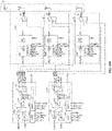
- FIG. 15A and FIG. 15B illustrate structural block diagrams of the radio-frequency system for the N77 and N79 frequency bands. Operating principles for SRS in the N77 and N79 frequency bands are similar as those in the N41 frequency band, which is not described in detail herein.
- Specific path configurations for 1T4R SRS are shown in Table 1. [Table 1] Detailed path configurations for 1T4R SRS N41 N77 N79 Channel 0 Path 1 Path 1 Path 1 Channel 1 Path 2->Path 5 Path 2->Path 5 Path 2->Path 5 Channel 2 Path 3->Path 6 Path 3->Path 6 Path 3->Path 6 Channel 3 Path 4->Path 7 Path 4->Path 7 Path 4->Path 7 Path 4->Path 7 Path 4->Path 7 Path 4->Path 7 Path 4->Path 7 Path 4->Path 7 Path 4->Path 7 Path 4->Path 7
- Channel 0, Channel 1, Channel 2, and Channel 3 are transmitting paths for polling transmission of the antennas.
- the antenna group 20 includes a first antenna Ant0, a second antenna Ant1, a third antenna Ant2, and a fourth antenna Ant3.
- two radio-frequency PA Mid devices 10 are provided and defined as a first radio-frequency PAMid device 11 and a second radio-frequency PAMid device 12, respectively.
- the first radio-frequency PAMid device 11 and the second radio-frequency PAMid device 12 have each a first antenna port SRS1, a second antenna port SRS2, a third antenna port SRS3, and a fourth antenna port SRS4.
- three radio-frequency L-DRX modules 30 are provided and defined as a first radio-frequency L-DRX module 31, a second radio-frequency L-DRX module 32, and a third radio-frequency L-DRX module 33, respectively.
- one second terminal of the multi-channel selection switch 130 is connected to the second antenna Ant1 via the first antenna port SRS1; another second terminal of the multi-channel selection switch 130 is connected to the first antenna Ant0 via the second antenna port SRS2 and the third switching unit 330 of the first radio-frequency L-DRX module 31; yet another second terminal of the multi-channel selection switch 130 is connected to the third antenna Ant2 via the third antenna port SRS3 and the third switching unit 330 of the second radio-frequency L-DRX module 32; and still yet another second terminal of the multi-channel selection switch 130 is connected to the fourth antenna Ant3 via the fourth antenna port SRS4 and the third switching unit 330 of the third radio-frequency L-DRX module 33.
- one second terminal of the multi-channel selection switch 130 is connected to the third antenna Ant2 via the third switching unit 330 of the second radio-frequency L-DRX module 32, and another second terminal of the multi-channel selection switch 130 is connected to the fourth antenna Ant3 via the third switching unit 330 of the third radio-frequency L-DRX module 33, to support a 2T4R SRS function.
- the radio-frequency system can support the quad-antenna 2T4R SRS function.
- Specific path configurations for 2T4R SRS are shown in Table 2. [Table 2] Detailed path configurations for 2T4R SRS N41 N77 N79 Channel 0 Path 1 Path 1 Path 1 Channel 1 Path 2->path 5 Path 2->path 5 Path 2->path 5 Channel 2 Path 8->Path 6 Path 8->Path 6 Path 8->Path 6 Channel 3 Path 9->Path 7 Path 9->Path 7 Path 9->Path 7 Path 9->Path 7 Path 9->Path 7 Path 9->Path 7
- Channel 0, Channel 1, Channel 2, and Channel 3 are transmitting paths for polling transmission of the antennas.
- the radio-frequency system can support the 1T4R SRS function or the 2T4R SRS function.
- the radio-frequency system by packaging the radio-frequency L-DRX module 30, the radio-frequency PA Mid device 10, the polling transmission of the radio-frequency signal at the first antenna Ant0, the second antenna Ant1, the third antenna Ant2, and the fourth antenna Ant3 can be realized without providing a plurality of independent cascade switches. In this way, the costs can be lowered, and an area of the substrate occupied by different components in the radio-frequency system can be reduced.
- a communication apparatus includes the radio-frequency transceiving system according to any of the above embodiments and a radio-frequency transceiver 90, which are disposed therein.
- the radio-frequency transceiver 90 may include a transmitter (e.g., transmitter TX) and a receiver (e.g., receiver RX); or the radio-frequency transceiver 90 may include the receiver (e.g., receiver RX) only; or the radio-frequency transceiver 90 may include the transmitter (e.g., transmitter TX) only.
- the radio-frequency transceiver 90 can be configured to implement a frequency conversion processing between an intermediate frequency signal and a baseband signal and/or to implement a frequency conversion processing between an intermediate frequency signal and a high frequency signal, or the like.
- the integration level of the radio-frequency transceiving system can be increased, and the area of the substrate occupied by different components in the radio-frequency transceiving system can be reduced.
- the power supply, logic control, and PCB layout and wiring of the radio-frequency L-DRX module 30 and the radio-frequency PA Mid device 10 can be simplified, thereby saving the costs.
Abstract
Description
- This application claims priorities to
Chinese Patent Applications No. 202010455914.2 No. 202020906935.7, entitled "RADIO FREQUENCY PA MID DEVICE, RADIO FREQUENCY TRANSCEIVING SYSTEM, AND COMMUNICATION APPARATUS", filed with China National Intellectual Property Administration on May 26, 2020 - The present disclosure relates to the field of radio-frequency technologies, and more particularly, to a radio-frequency Power Amplifier Modules including Duplexers (PA Mid) device, a radio-frequency transceiving system, and a communication apparatus.
- The statements here provide only background information relevant to the present disclosure and do not necessarily constitute example related art.
- With the development and advancement of technology, 5-th generation (5G) mobile communication technology has been increasingly applied to electronic devices. 5G mobile communication technology has a higher communication frequency than 4G mobile communication technology. Generally, in order to support polling transmission of a radio-frequency signal among multiple antennas, a plurality of discrete switches is required to be disposed in transmitting paths of a radio-frequency system to support polling transmission of a radio-frequency signal among a plurality of antennas, thereby leading to higher cost and occupying a relatively large area of a substrate.
- According to embodiments of the present disclosure, a radio-frequency PA Mid device, a radio-frequency transceiving system, and a communication apparatus are provided.
- The radio-frequency PA Mid device has a transmitting port configured to connect to a radio-frequency transceiver and a plurality of antenna ports each configured to connect to an antenna. The radio-frequency PA Mid device includes a power amplifier, a first filtering unit, and a multi-channel selection switch. The power amplifier has an input terminal connected to the transmitting port, and the power amplifier is configured to perform a power amplification processing on a received radio-frequency signal. The first filtering unit is connected to an output terminal of the power amplifier, and the first filtering unit is configured to perform a filtering processing on the received radio-frequency signal. The multi-channel selection switch has at least one first terminal and a plurality of second terminals. One of the at least one first terminal is connected to the first filtering unit, and the plurality of second terminals is connected to the plurality of antenna ports in a one-to-one correspondence. The multi-channel selection switch is configured to selectively switch on a transmitting path between the transmitting port and any one of the plurality of antenna ports for transmission of the radio-frequency signal and supporting a function of polling transmission of a Sounding Reference Signal (SRS) among the plurality of antenna ports.
- The radio-frequency transceiving system includes an antenna group, a radio-frequency L-DRX module connected to the first antenna, and the above-mentioned radio-frequency PA Mid device. The antenna group at least includes a first antenna and a second antenna, and the antenna group is configured to transmit and receive a radio-frequency signal. The radio-frequency L-DRX module is configured to receive the radio-frequency signal inputted via the second antenna. One of the plurality of antenna ports of the radio-frequency PA Mid device is connected to the second antenna, and another one of the plurality of antenna ports being connected to the radio-frequency L-DRX module. The radio-frequency PA Mid device is configured to support a function of polling transmission of SRS between the first antenna and the second antenna.
- The communication apparatus includes a radio-frequency transceiver, and the above-mentioned radio-frequency transceiving system. The radio-frequency transceiving system is connected to the radio-frequency transceiver.
- In the above-mentioned radio-frequency PA Mid device, radio-frequency transceiving system, and communication apparatus, the power amplifier, the first filtering unit, and the multi-channel selection switch in the radio-frequency PA Mid device are all integrated and packaged in the same chip, thereby increasing an integration level of the radio-frequency PA Mid device, while reducing the costs and an area of a substrate occupied by various components in a radio-frequency system. By integrating the multi-channel selection switch into the radio-frequency PA Mid device, an area of at least 10 mm2 can be saved, when compared with the case that the multi-channel selection switch is disposed outside the radio-frequency PA Mid device. In this way, more space can be saved for performance optimization of other modules. Further, the radio-frequency PA Mid device integrated with the multi-channel selection switch has the same as the radio-frequency PA Mid device without the multi-channel selection switch. That is, the size of the radio-frequency PA Mid device is unchanged by integrating the multi-channel selection switch into the radio-frequency
PA Mid device 10. - One or more of the embodiments of the present disclosure are described in detail below in combination with the accompanying drawings. Other features, objects and advantages of the present disclosure will become apparent from the specification, the accompanying drawings, and the claims as attached.
- In order to clearly explain technical solutions of embodiments of the present disclosure or in the related art, drawings used in description of the embodiments or the related art will be briefly described below. The drawings described below merely illustrate some embodiments of the present disclosure. Based on these drawings, other drawings can be obtained by those skilled in the art without paying creative efforts.
-
FIG. 1 is a first schematic structural diagram of a radio-frequency PA Mid device according to an embodiment of the present disclosure. -
FIG. 2 is a second schematic structural diagram of a radio-frequency PA Mid device according to an embodiment of the present disclosure. -
FIG. 3 is a third schematic structural diagram of a radio-frequency PA Mid device according to an embodiment of the present disclosure. -
FIG. 4A is a fourth schematic structural diagram of a radio-frequency PAMid device according to an embodiment of the present disclosure. -
FIG. 4B is a fifth schematic structural diagram of a radio-frequency PA Mid device according to an embodiment of the present disclosure. -
FIG. 5A is a sixth schematic structural diagram of a radio-frequency PAMid device according to an embodiment of the present disclosure. -
FIG. 5B is a seventh schematic structural diagram of a radio-frequency PA Mid device according to an embodiment of the present disclosure. -
FIG. 5C is an eighth schematic structural diagram of a radio-frequency PA Mid device according to an embodiment of the present disclosure. -
FIG. 5D is a ninth schematic structural diagram of a radio-frequency PAMid device according to an embodiment of the present disclosure. -
FIG. 6A is a first schematic diagram of a pin configuration of a radio-frequency PA Mid device according to an embodiment of the present disclosure. -
FIG. 6B is a schematic diagram of a packaging structure of a radio-frequency PA Mid device inFIG. 6A . -
FIG. 6C is a second schematic diagram of a pin configuration of a radio-frequency PAMid device according to an embodiment of the present disclosure. -
FIG. 6D is a schematic diagram of a packaging structure of a radio-frequency PA Mid device inFIG. 6C . -
FIG. 7A is a third schematic diagram of a pin configuration of a radio-frequency PA Mid device according to an embodiment of the present disclosure. -
FIG. 7B is a schematic diagram of a packaging structure of a radio-frequency PA Mid device inFIG. 7A . -
FIG. 7C is a fourth schematic diagram of a pin configuration of a radio-frequency PA Mid device according to an embodiment of the present disclosure. -
FIG. 7D is a schematic diagram of a packaging structure of a radio-frequency PA Mid device inFIG. 7C . -
FIG. 8 is a first schematic structural diagram of a radio-frequency transceiving system according to an embodiment of the present disclosure. -
FIG. 9 is a first schematic structural diagram of a radio-frequency L-DRX module according to an embodiment of the present disclosure. -
FIG. 10A is a second schematic structural diagram of a radio-frequency L-DRX module according to an embodiment of the present disclosure. -
FIG. 10B is a third schematic structural diagram of a radio-frequency L-DRX module according to an embodiment of the present disclosure. -
FIG. 11A is a fourth schematic structural diagram of a radio-frequency L-DRX module according to an embodiment of the present disclosure. -
FIG. 11B is a fifth schematic structural diagram of a radio-frequency L-DRX module according to an embodiment of the present disclosure. -
FIG. 12A is a first schematic diagram of an application scenario for a feedback channel information transmission of a communication apparatus according to an embodiment. -
FIG. 12B is a second schematic diagram of an application scenario for a feedback channel information transmission of a communication apparatus according to an embodiment. -
FIG. 13 is a schematic structural diagram of a mode of antenna polling transmission of SRS according to an embodiment. -
FIG. 14A is a second schematic structural diagram of a radio-frequency transceiving system according to an embodiment of the present disclosure. -
FIG. 14B is a third schematic structural diagram of a radio-frequency transceiving system according to an embodiment of the present disclosure. -
FIG. 15A is a fourth schematic structural diagram of a radio-frequency transceiving system according to an embodiment of the present disclosure. -
FIG. 15B is a fifth schematic structural diagram of a radio-frequency transceiving system according to an embodiment of the present disclosure. -
FIG. 16A is a sixth schematic structural diagram of a radio-frequency transceiving system according to an embodiment of the present disclosure. -
FIG. 16B is a seventh schematic structural diagram of a radio-frequency transceiving system according to an embodiment of the present disclosure. -
FIG. 17 is a schematic structural diagram of a communication apparatus according to an embodiment of the present disclosure. - In order to facilitate understanding of the present disclosure and to clarify the above-mentioned objects, features, and advantages of the present disclosure, specific embodiments of the present disclosure are described in detail below in conjunction with the accompanying drawings. In the following description, many specific details are provided to facilitate full understanding of the present disclosure. Preferred embodiments of the present disclosure are illustrated by means of the accompanying drawings. However, the present disclosure can be implemented in various forms and is not limited to the embodiments described herein. On the contrary, these embodiments are merely provided to facilitate thorough and comprehensive understanding of the content of the present disclosure. The present disclosure can be implemented in various manners other than those described herein, and similar improvements can be made by those skilled in the art without contradicting the intent of the present disclosure. Therefore, the present disclosure is not limited by specific embodiments disclosed below.
- In addition, the term "first" or "second" is only for descriptive purposes, and it cannot be indicating or implying relative importance or implicitly indicating the number of indicated technical features. Therefore, the features defined with "first" or "second" can explicitly or implicitly include at least one of the features. In the description of the present disclosure, "plurality of' means at least two, unless otherwise specifically indicated. In the present disclosure, "a number of' means at least one, unless otherwise specifically indicated.
- A radio-frequency transceiving system involved in the embodiments of the present disclosure can be applied to a communication apparatus having wireless communication capabilities. The communication apparatus may be a handheld apparatus, a vehicle-mounted apparatus, a wearable apparatus, a computing apparatus, any other processing apparatuses connected to a wireless modem, a user equipment (UE) in various forms (e.g., a mobile phone), or a mobile station (MS), etc. For ease of description, the above-mentioned apparatuses can be collectively referred to as the communication apparatus. A network device may include a base station, an access point, etc.
- According to an embodiment of the present disclosure, a radio-frequency PA Mid device is provided. As illustrated in
FIG. 1 , in an embodiment, the radio-frequencyPA Mid device 10 can be used to support control of polling transmission of radio-frequency signals among a plurality of antennas. As an example, a radio-frequencyPA Mid device 10 has a plurality of transmitting paths for transmitting radio-frequency signals, to support a function of polling transmission of SRS among a plurality of antenna ports. - In an embodiment, the radio-frequency signal may be a 5G signal, such as a 5G signal in an N41 frequency band, a radio-frequency signal in an N77 frequency band, a radio-frequency signal in an N78 frequency band, a radio-frequency signal in an N79 frequency band, etc. As an example, an operating frequency band of N41 ranges from 496 MHz to 2,690 MHz; an operating frequency band of N77 ranges from 3.3 GHz to 4.2 GHz; an operating frequency band of N78 ranges from 3.3 GHz to 3.8 GHz; and an operating frequency band of N79 ranges from 4.4 GHz to 5.0 GHz. It should be noted that the operating frequency band of N77 covers the operating frequency band of N78. That is, when the radio-
frequency PAMid device 10 can support a transceiving of radio-frequency signals in the N77 frequency band, it can also support a transceiving of radio-frequency signals in the N78 frequency band. It should be noted that the radio-frequency signals may also be Long-Term Evolution (LTE) signals, Wireless Fidelity (WiFi) signals, etc. In the embodiments of the present disclosure, the operating frequency band of the radio-frequency signals is not further limited. - In an embodiment, the radio-frequency
PA Mid device 10 has a transmitting port RFIN and a plurality of antenna ports SRS (e.g., SRS1, SRS2, SRS3, SRS4). The radio-frequencyPA Mid device 10 can be regarded as a packaged chip. The transmitting port RFIN and the antenna ports SRS provided in the radio-frequency PAMid device 10 can be regarded as radio-frequency pin terminals of the radio-frequencyPA Mid device 10 for connecting to various external devices. As an example, the transmitting port RFIN may be used configured to connect to a radio-frequency transceiver. The plurality of antenna ports SRS may be used configured to connect to antennas. - In an embodiment, the radio-
frequency PAMid device 10 includes apower amplifier 110, afirst filtering unit 120, and amulti-channel selection switch 130. The transmitting port RFIN of the radio-frequencyPA Mid device 10 is connected to the plurality of antenna ports SRS through thepower amplifier 110, thefirst filtering unit 120, and themulti-channel selection switch 130 in sequence. - As an example, the
power amplifier 110 has an input terminal connected to the transmitting port RFIN, and thepower amplifier 110 is configured to perform a power amplification processing on a received radio-frequency signal inputted via a receiving port. Thefirst filtering unit 120 is connected to an output terminal of thepower amplifier 110. Thefirst filtering unit 120 is configured to receive the radio-frequency signal processed by thepower amplifier 110 and filter the received radio-frequency signal. - The
multi-channel selection switch 130 includes at least one first terminal and a plurality of second terminals. One first terminal of themulti-channel selection switch 130 is connected to thefirst filtering unit 120. The plurality of second terminals is connected to the plurality of antenna ports SRS in a one-to-one correspondence. Themulti-channel selection switch 130 is configured to selectively switch on a transmitting path between the transmitting port RFIN and any one antenna port SRS, for transmitting the radio-frequency signal and supporting a function of polling transmission of SRS among the plurality of antenna ports SRS. The number of the second terminals of themulti-channel selection switch 130 is the same as the number of the antenna ports SRS. One antenna port SRS is correspondingly connected to one second terminal of themulti-channel selection switch 130. Further, each antenna port SRS may be correspondingly connected to at least one antenna. - For example, the radio-frequency
PA Mid device 10 may have two antenna ports SRS, which can be defined as a first antenna port SRS1 and a second antenna port SRS2. The first antenna port SRS1 can be connected to a first antenna, and the second antenna port SRS2 can be connected to a second antenna. Themulti-channel selection switch 130 may be a Single-Pole Double-Throw (SPDT) switch. The SPDT switch has two selection terminals connected to the first antenna port SRS1 and the second antenna port SRS2, respectively, thereby achieving the polling transmission of SRS by the first antenna and the second antenna. That is, the radio-frequency signal is inputted to the radio-frequencyPA Mid device 10 via the transmitting port RFIN; the radio-frequency signal reaches themulti-channel selection switch 130 via thepower amplifier 110 and thefirst filtering unit 120, switched to the firstantenna port SRS 1; and the radio-frequency signal is transmitted via the first antenna. Further, the radio-frequency signal may be switched to the second antenna port SRS2 through themulti-channel selection switch 130 and transmitted via the second antenna. - For example, the radio-frequency
PA Mid device 10 may have four antenna ports SRS, which can be defined as a first antenna port SRS1, a second antenna port SRS2, a third antenna port SRS3, and a fourth antenna port SRS4. The first antenna port SRS1 can be connected to a first antenna. The second antenna port SRS2 can be connected to a second antenna. The third antenna port SRS3 can be connected to a third antenna. The fourth antenna port SRS4 can be connected to a fourth antenna. Themulti-channel selection switch 130 can be a Single-Pole Four-Throw (SP4T) switch. The SP4T switch has four selection terminals connected to the first antenna port SRS1, the second antenna port SRS2, the third antenna port SRS3, and the fourth antenna port SRS4, respectively. Through switching control of themulti-channel selection switch 130, the polling transmission of SRS by the first antenna, the second antenna, the third antenna, and the fourth antenna can be realized. - In the embodiments of the present disclosure, the radio-
frequency PAMid device 10 can be regarded as a packaged chip. That is, thepower amplifier 10, thefirst filtering unit 120, and themulti-channel selection switch 130 in the radio-frequencyPA Mid device 10 are all integrated and packaged in the same chip. In this way, an integration level of the radio-frequencyPA Mid device 10 can be increased, the cost thereof is lowered, while reducing an area of a substrate occupied by various components in a radio-frequency system. By integrating themulti-channel selection switch 130 into the radio-frequencyPA Mid device 10, an area of at least 10 mm2 can be saved, when compared with the case that themulti-channel selection switch 130 is disposed outside the radio-frequencyPA Mid device 10. In this way, more space can be saved for performance optimization of other modules. Further, the radio-frequencyPA Mid device 10 integrated with themulti-channel selection switch 130 has the same as the radio-frequencyPA Mid device 10 without themulti-channel selection switch 130. That is, the size of the radio-frequencyPA Mid device 10 is unchanged by integrating themulti-channel selection switch 130 into the radio-frequencyPA Mid device 10. - In an embodiment, the
first filtering unit 120 includes a band-pass filter or a low-pass filter. It should be noted that a type of thefirst filtering unit 120 can be selected based on the operating frequency band of the radio-frequency signal supportable by the radio-frequencyPA Mid device 10. For example, when the radio-frequency signal supported by the radio-frequencyPA Mid device 10 is a 5G signal in the N41 frequency band, thefirst filtering unit 120 of the radio-frequency PAMid device 10 may be a low-pass filter, which only allows radio-frequency signals in the N41 frequency band to pass through and filters out spurious waves outside of the N41 frequency band; when the radio-frequency signal supported by the radio-frequencyPA Mid device 10 is a 5G signal in the N77 frequency band, thefirst filtering unit 120 of the radio-frequencyPA Mid device 10 may be a band-pass filter, which only allows radio-frequency signals in the N77 frequency band to pass through and filters out spurious waves outside of the N77 frequency band; and when the radio-frequency signal supported by the radio-frequencyPA Mid device 10 is a 5G signal in the N79 frequency band, thefirst filtering unit 120 of the radio-frequencyPA Mid device 10 may be a band-pass filter, which only allows radio-frequency signals in the N79 frequency band to pass through and filters out spurious waves outside of the N79 frequency band. - It should be noted that in the embodiments of the present disclosure, a suitable filter can be selected based on the frequency band of the radio-frequency signal, to perform a filtering processing on the radio-frequency signal.
- As illustrated in
FIG. 2 , in an embodiment, the radio-frequencyPA Mid device 10 has a receiving port RXOUT configured to connect to the radio-frequency transceiver. The radio-frequency PAMid device 10 further includes afirst switching unit 140. Thefirst switching unit 140 has a control terminal connected to thefirst filtering unit 120, a first selection terminal connected to the output terminal of thepower amplifier 110, and a second selection terminal connected to the receiving port RXOUT. Thefirst switching unit 140 is configured to selectively switch on a receiving path where the receiving port RXOUT is located and the transmitting path where the transmitting port RFIN is located. - As an example, the
first switching unit 140 may be a radio-frequency SPDT switch. That is, the control terminal of the radio-frequency SPDT switch is connected to asecond filtering unit 320, the first selection terminal of the radio-frequency SPDT switch is connected to the receiving port RXOUT, and the second selection terminal of the radio-frequency SPDT switch is connected to the output terminal of thepower amplifier 110, to selectively switch on the receiving path and the transmitting path of the radio-frequency PAMid device 10. - In this embodiment, by means of disposing the
first switching unit 140 in the radio-frequency PAMid device 10, the radio-frequency PAMid device 10 can be provided with the receiving path and the transmitting path, which can perform the transceiving control of the radio-frequency signal in turn. For example, the transmitting control of the radio-frequency signal can be achieved in such a manner that, the radio-frequency signal is inputted from the transmitting port RFIN, it reaches thefirst switching unit 140 via thepower amplifier 110, it is switched to thefirst filtering unit 120 by thefirst switching unit 140 and switched to any antenna port SRS by a multi-channel switch, and the radio-frequency signal is outputted by the antenna port SRS, to achieve transmitting control of the radio-frequency signal. The receiving control of the radio-frequency signal can be achieved in such a manner that the radio-frequency signal is received by any antenna port SRS, it reaches thefirst filtering unit 120 via themulti-channel selection switch 130, and it is switched to the receiving port RXOUT by thefirst switching unit 140. - As illustrated in
FIG. 3 , in an embodiment, the radio-frequencyPA Mid device 10 has a receiving port RXOUT configured to connect to the radio-frequency transceiver and further includes asecond filtering unit 150. Themulti-channel selection switch 130 is a radio-frequency Double-Pole Four-Throw (DP4T) switch including two first terminals and four second terminals. Thesecond filtering unit 150 is connected to each of the receiving port RXOUT and another first terminal of themulti-channel selection switch 130 to form a receiving path. Thesecond filtering unit 150 is configured to perform a filtering processing on the radio-frequency signal received by any antenna port SRS. - In an embodiment, the
second filtering unit 150 includes a low-pass filter or a band-pass filter. It should be noted that a type of thesecond filtering unit 150 can be selected based on the operating frequency band of the radio-frequency signal supportable by the radio-frequency PAMid device 10. For example, the type of filtering of thesecond filtering unit 150 may be the same as that of thefirst filtering unit 120, both of which can perform a filtering processing on the radio-frequency signal transmitted and received by the radio-frequency system. - In contrast to the embodiment illustrated in
FIG. 3 , in this embodiment, thefirst switching unit 140 is omitted and thesecond filtering unit 150 is added to form the receiving path for receiving the radio-frequency signal. It should be noted that in this embodiment, themulti-channel selection switch 130 is the radio-frequency DP4T switch and has two first terminals. One first terminal of themulti-channel selection switch 130 is connected to the receiving port RXOUT via thesecond filtering unit 150, and the other one first terminal of themulti-channel selection switch 130 is connected to the transmitting port RFIN via thefirst filtering unit 120 and thepower amplifier 110. - For example, when the
multi-channel selection switch 130 is the radio-frequency SP4T switch, the values of insertion loss of the radio-frequency SP4T switch (e.g., MXD8643) are as illustrated in Table 1. In the radio-frequency system, radio-frequency cable losses for respective frequency bands are as illustrated in Table 2.[Table 1] Values of insertion loss of an SP4T switch Frequency band (GHz) N41 N77 N79 Insertion loss (dB) 0.65 0.7 0.8 [Table 2] Values of radio-frequency cable loss of link Frequency band (GHz) N41 N77 N79 Insertion loss (dB) 2.8 2.9 2.8 - The insertion loss on a transceiving channel is reduced by removing the
first switching unit 140 inside the radio-frequencyPA Mid device 10. As an example, when the first radio-frequency signal is an N41 signal and input power of the transmitting port RFIN is 28.5 dBm, output power of the antenna port SRS is 25.9 dBm, and output powers of the antenna port SRS in N77 and N79 are as illustrated in Table 3. As can be seen from Table 3, the output power of the antenna port SRS is guaranteed.[Table 3] Values of output power for the antenna port SRS Frequency band (GHz) N41 N77 N79 Antenna port SRS power (dB) 25.9 25.65 25.8 - In this embodiment, the
first switching unit 140 is omitted and only themulti-channel selection switch 130 is retained, which can reduce a link loss of the transceiving channel of the radio-frequency PAMid device 10. In this way, the output power of the antenna port SRS can meet communication requirements. - In an embodiment, as illustrated in
FIG. 4A and FIG. 4B , when the radio-frequencyPA Mid device 10 is used to support transceiving control of the radio-frequency signal in the N77 frequency band or the N97 frequency band, the radio-frequencyPA Mid device 10 further includes a firstlow noise amplifier 160. The firstlow noise amplifier 160 is disposed in the receiving path and configured to amplify the radio-frequency signal received by any antenna port SRS. The radio-frequency signal is outputted via the receiving port RXOUT. Referring toFIG. 4A , when the radio-frequency PAMid device 10 includes thefirst switching unit 140, the input terminal of the firstlow noise amplifier 160 is connected to a selection terminal of thefirst switching unit 140, and the output terminal of the firstlow noise amplifier 160 is connected to the receiving port RXOUT. Referring toFIG. 4B , when the radio-frequencyPA Mid device 10 includes thesecond filtering unit 150, the input terminal of the firstlow noise amplifier 160 is connected to thesecond filtering unit 150 and the output terminal of the firstlow noise amplifier 160 is connected to the receiving port RXOUT. - By disposing the first
low noise amplifier 160 in the receiving path of the radio-frequencyPA Mid device 10, the radio-frequency signal can be amplified to meet communication requirements of the receiving path. - As illustrated in
FIG. 5A to FIG. 5D , in an embodiment, the radio-frequency PAMid device 10 has a coupling output port CPLOUT, and the radio-frequencyPA Mid device 10 further includes acoupling circuit 170. Thecoupling circuit 170 is coupled to thefirst filtering unit 120 and the first terminal of themulti-channel selection switch 130, and thecoupling circuit 170 is connected to the coupling output port CPLOUT. Thecoupling circuit 170 is configured to couple the radio-frequency signal to output a coupling signal for measuring power information. As an example, the coupling signal includes a forward coupling signal and a reverse coupling signal. - In an embodiment, the
coupling circuit 170 includes acoupling unit 171 and acoupling switch 173. Thecoupling unit 171 is configured to couple the radio-frequency signal in the transmitting path to realize a coupled output of the radio-frequency signal, which can be used to measure coupling power of the radio-frequency signal. As an example, referring toFIG. 5A , thecoupling unit 171 includes an input terminal a, an output terminal b, a first coupling terminal c, and a second coupling terminal d. Further, thecoupling unit 171 further includes a primary line extending between the input terminal a and the output terminal b and a secondary line extending between the first coupling terminal c and the second coupling terminal d. - As an example, the input terminal a of the
coupling unit 171 is coupled to thefirst filtering unit 120. The output terminal b of thecoupling unit 171 is coupled to the first terminal of themulti-channel selection switch 130. The first coupling terminal c is configured to couple the radio-frequency signal received at the input terminal a and output a forward coupling signal. The second coupling terminal d is configured to couple a reflected signal of the radio-frequency signal received at the output terminal b and output a reverse coupling signal. Forward power information of the radio-frequency signal can be detected based on the forward coupling signal outputted at the first coupling terminal c. Correspondingly, reverse power information of the radio-frequency signal can be detected based on the reverse coupling signal outputted at the second coupling terminal d. Such a detection mode is defined as a reverse power detection mode. - The
coupling switch 173 is connected to the first coupling terminal c, the second coupling terminal d, and the coupling output port CPLOUT. Thecoupling switch 173 is configured to selectively switch on a first coupling path between the first coupling terminal c and the coupling output port CPLOUT to detect forward power of the radio-frequency signal, in which case such a detection mode is defined as a forward power detection mode; or thecoupling switch 173 is configured to selectively switch on a second coupling path between the second coupling terminal d and the coupling output port CPLOUT to detect reverse power of the radio-frequency signal, in which case such a detection mode is defined as the reverse power detection mode. That is, thecoupling switch 173 is configured to switch between the forward power detection mode and the reverse power detection mode. As an example, thecoupling unit 171 includes two directional couplers connected in reverse series. - In this embodiment, the radio-frequency
PA Mid device 10 only has one coupling output port CPLOUT, which can meet the communication requirements. In addition, by providing only one coupling output port CPLOUT, the complexity of radio-frequency wirings inside the radio-frequencyPA Mid device 10 can be reduced, thereby improving isolation performance of the respective wirings of the radio-frequency PAMid device 10. - In an embodiment, with reference to
FIG. 5B , the radio-frequencyPA Mid device 10 may further have a coupling input port CPLIN for receiving coupling signals from other radio-frequency PAMid devices 10. - In an embodiment, the radio-frequency
PA Mid device 10 further includes at least onecontrol unit 180. Referring toFIG. 5A and FIG. 5B , when the radio-frequencyPA Mid device 10 supports the transceiving control of radio-frequency signals in the N41 frequency band, the radio-frequency PAMid device 10 includes onecontrol unit 180. Thecontrol unit 180 is connected to thepower amplifier 110, thefirst switching unit 140, and thecoupling switch 173. Thecontrol unit 180 is configured to control a gain coefficient of thepower amplifier 110 and control selective switching-on states of thefirst switching unit 140 and thecoupling switch 173. Referring toFIG. 5C and FIG. 5D , when the radio-frequencyPA Mid device 10 supports transceiving control of radio-frequency signals in the N77 or N79 frequency band, anadditional control unit 180 connected to the second low noise amplifier 350 may be provided. Theadditional control unit 180 is configured to adjust a gain coefficient of the firstlow noise amplifier 160 to adjust an insertion loss of a receiving link in the radio-frequency PAMid device 10. Thus, the sensitivity of its radio-frequency system can be improved. - In an embodiment, the
control unit 180 may be a Radio Frequency Front End Control Interface (RFFE)control unit 180. When thecontrol unit 180 is theRFFE control unit 180, its radio-frequencyPA Mid device 10 further has an input pin CLK for clock signals, an input or bidirectional pin SDATAS for single/bidirectional data signals, a reference voltage pin VIO, etc. For example, theRFFE control unit 180 may output clock and data signals to corresponding pins of thefirst switching unit 140 and thecoupling switch 173 for on/off control of the transceiving path or the coupling path. The Mobile Industry Processor Interface (MIPI)-RFFE control unit 180 may output clock and data signals to the firstlow noise amplifier 160 to achieve gain adjustment control of the firstlow noise amplifier 130, or it may output the clock and data signals to thepower amplifier 110 to control an operating state of thepower amplifier 110. - In an embodiment, each component included in the radio-
frequency PAMid device 10 may be integrated in the same chip through a packaging process. That is, the radio-frequencyPA Mid device 10 may be regarded as a packaged chip. When thefirst switching unit 140 is integrated in the radio-frequency PAMid device 10 and the radio-frequency PAMid device 10 supports radio-frequency transceiving of signals in the N41 frequency band, the radio-frequencyPA Mid device 10 has a pin configuration as illustrated inFIG. 6A . The respective pins in this chip correspond to the plurality of ports provided in the radio-frequencyPA Mid device 10 in a one-to-one correspondence. Through packaging integration, the radio-frequencyPA Mid device 10 has a package structure as illustrated inFIG. 6B , which can improve the integration level of the radio-frequencyPA Mid device 10. Accordingly, when the radio-frequencyPA Mid device 10 supports the radio-frequency transceiving of signals in the N77 or N79 frequency band, the radio-frequencyPA Mid device 10 has a pin configuration as illustrated inFIG. 6C and a package structure as illustrated inFIG. 6D . - In an embodiment, when the
second filtering unit 150 is integrated in the radio-frequencyPA Mid device 10 and the radio-frequencyPA Mid device 10 supports the radio-frequency transceiving in the N41 frequency band, the radio-frequencyPA Mid device 10 has a pin configuration as illustrated inFIG. 7A . The respective pins in this chip correspond to the plurality of ports provided in the radio-frequencyPA Mid device 10 in a one-to-one correspondence. Through packaging integration, the radio-frequencyPA Mid device 10 has a package structure as illustrated inFIG. 7B , which can improve the integration level of the radio-frequency PAMid device 10. - It should be noted that according to an embodiment of the present disclosure, the radio-frequency
PA Mid device 10 can support the transmitting control or transceiving control of 5G signals in the N41, N77, N79 frequency bands, etc. Accordingly, when the radio-frequencyPA Mid device 10 supports the radio-frequency transceiving of signals in the N77 or N79 frequency band, the radio-frequencyPA Mid device 10 has a pin configuration as illustrated inFIG. 7C and a package structure as illustrated inFIG. 7D . - According to an embodiment of the present disclosure, a radio-frequency transceiving system is further provided. As illustrated in
FIG. 8 , in an embodiment, the radio-frequency transceiving system includes anantenna group 20, a radio-frequency L-DRX module 30, and the radio-frequency PAMid device 10 according to any of the above embodiments. - In an embodiment, the
antenna assembly 20 at least includes a first antenna AntO and a second antenna Ant1. The first antenna AntO and the second antenna Ant1 can both support the radio-frequency signals in different operating frequency bands, e.g., LTE signals, WiFi signals, 5G New Radio (NR) signals, etc. The first antenna Ant0 can be configured to receive and transmit (i.e., transceive) radio-frequency signals in different frequency bands. The second antenna Ant1 can be configured to transceive radio-frequency signals in different frequency bands. - In an embodiment, the first antenna Ant0 and the second antenna Ant1 may be directional or non-directional antennas. For example, the first antenna Ant0 and the second antenna Ant1 may be formed by any suitable type of antenna. For example, the first antenna Ant0 and the second antenna Ant1 may include an antenna having a resonant element and formed by at least one of the following antenna structures: an array antenna structure, a loop antenna structure, a patch antenna structure, a slot antenna structure, a spiral antenna structure, a strip antenna, a monopole antenna, a dipole antenna, or the like. Different types of antennas can be used for combinations of frequency bands of different radio-frequency signals.
- The
antenna assembly 20 may further include a third antenna and a fourth antenna. In the embodiments of the present disclosure, the number and type of antennas included in theantenna assembly 20 are not limited and can be determined as desired. - The radio-frequency L-
DRX module 30 is connected to the first antenna Ant0 and one antenna port SRS of the radio-frequencyPA Mid device 10. The radio-frequency L-DRX module 30 is configured to receive the radio-frequency signal inputted by the first antenna Ant0 and transmit the radio-frequency signal outputted by the one antenna port SRS of the radio-frequencyPA Mid device 10 to the first antenna Ant0, by which the radio-frequency signal is transmitted. That is, the radio-frequency L-DRX module 30 may selectively switch on another receiving path in the radio-frequency system where the radio-frequency L-DRX module 30 is located to receive the radio-frequency signal inputted from the first antenna Ant0. - One antenna port SRS of the radio-frequency
PA Mid device 10 is connected to the second antenna Ant1, and another antenna port SRS thereof is connected to the radio-frequency L-DRX module 30, to support a function of polling transmission of SRS between the first antenna Ant0 and the second antenna Ant1. The radio-frequency L-DRX module 30 can also switch on another transmitting path in the radio-frequency system where the radio-frequencyPA Mid device 10 is located, and thus the radio-frequency signal outputted from one antenna port SRS of the radio-frequencyPA Mid device 10 can be outputted via the second antenna Ant1. - In the radio-frequency system according to the above embodiments, the
multi-channel selection switch 130 integrated in the radio-frequencyPA Mid device 10, in combination with the radio-frequency L-DRX module 30, can realize the polling transmission of the radio-frequency signal between the first antenna Ant0 and the second antenna Ant1 without providing a plurality of independent cascade switches. In this way, the costs can be lowered, and an area of the substrate occupied by different components in the radio-frequency system can be reduced. - As illustrated in
FIG. 9 , in an embodiment, the radio-frequency L-DRX module 30 includes a secondlow noise amplifier 310, athird filtering unit 320, and athird switching unit 330. The secondlow noise amplifier 310 has an input terminal connected to thethird filtering unit 320. The secondlow noise amplifier 310 is configured to amplify the received radio-frequency signal and output, via an output terminal thereof, the amplified radio-frequency signal to the radio-frequency transceiver. Thethird filtering unit 320 is connected to thethird switching unit 330 and configured to perform a filtering processing on the radio-frequency signal received by the first antenna Ant0. Thethird switching unit 330 is connected to the first antenna Ant0 and one antenna port SRS of the radio-frequencyPA Mid device 10. Thethird switching unit 330 is configured to selectively switch on a receiving path where the secondlow noise amplifier 310 is located and a transmitting path where the radio-frequency PAMid device 10 is located. - In an embodiment, the
third switching unit 330 may be the radio-frequency SPDT switch. That is, the radio-frequency SPDT switch has the control terminal connected to the first antenna Ant0, the first selection terminal connected to thethird filtering unit 320, and the second selection terminal connected to one antenna port SRS of the radio-frequency PAMid device 10, to selectively switch on the receiving path where the secondlow noise amplifier 310 is located and the transmitting path where the radio-frequency PAMid device 10 is located. - Referring to
FIG. 9 , in an embodiment, when the radio-frequency L-DRX module 30 is configured to support radio-frequency signals in the N41 frequency band, the radio-frequency L-DRX module 30 further includes abypass switch 340 in parallel with the secondlow noise amplifier 310. When the radio-frequency system receives radio-frequency signals received by the plurality of antennas, thebypass switch 340 may be controlled to be turned off in the event of a large blocking signal to prevent the radio-frequency signal from being received at too high power to saturate the RF transceiver. - In an embodiment, referring to
FIG. 9 , the secondlow noise amplifier 310 and thebypass switch 340 are packaged in the same chip. When the secondlow noise amplifier 310 and thebypass switch 340 are packaged in the same chip, the chip may be regarded as a Low Noise Amplifier (LNA) device having the radio-frequency receiving port RXOUT and the radio-frequency antenna port ANT. The input terminal of the secondlow noise amplifier 310 is connected to the radio-frequency antenna port ANT. The output terminal of the secondlow noise amplifier 310 is connected to the radio-frequency receiving port RXOUT. The integration level of the LNA device can be improved by packaging the secondlow noise amplifier 310 and thebypass switch 340 in the same chip. - As illustrated in
FIG. 10A and FIG. 10B , in an embodiment, when the radio-frequency L-DRX module 30 is configured to support radio-frequency signals in the N77 and N79 frequency bands, the secondlow noise amplifier 310 and thethird filtering unit 320 are packaged in the same chip. The packaged chip is regarded as the LNA device. Thethird switching unit 330 and the LNA device are two discrete devices. - As in the previous embodiments, the LNA device further has the radio-frequency antenna port ANT and the radio-frequency receiving port RXOUT. The radio-frequency antenna port ANT is connected to the radio-frequency receiving port RXOUT via the
third filtering unit 320 and the secondlow noise amplifier 310. Further, the LNA device is further integrated with acontrol unit 180 configured to control the secondlow noise amplifier 310, to adjust the gain coefficient of the low noise amplifier. Therefore, a receiving power of the radio-frequency signal at the radio-frequency receiving port RXOUT can be adjusted. - As illustrated in
FIG. 11A , in an embodiment, the secondlow noise amplifier 310, thethird filtering unit 320, and thethird switching unit 330 are all packaged in the same chip. The packaged chip serves as the LNA device. As an example, the LNA device can have the radio-frequency receiving port RXOUT, the radio-frequency transmitting port SRS, and the radio-frequency antenna port ANT. The control terminal of thethird switching unit 330 is connected to the radio-frequency antenna port ANT. One selection terminal of thethird switching unit 330 is connected to thethird filtering unit 320. Another selection terminal of thethird switching unit 330 is connected to one antenna port SRS of the radio-frequencyPA Mid device 10 via a radio-frequency transmitting terminal. - For example, the
third switching unit 330 is taken as the radio-frequency SPDT switch to describe the transceiving control of the radio-frequency signal of the radio-frequency L-DRX module 30. - Receiving control: the radio-frequency signal received by the antenna is received via the radio-frequency antenna port ANT. That is, the radio-frequency signal enters the radio-frequency SPDT switch via the radio-frequency antenna port ANT. The radio-frequency SPDT switch is switched to the
third filtering unit 320 to switch on the receiving path. The radio-frequency signal is transmitted to the radio-frequency receiving port RXOUT via the secondlow noise amplifier 310. The radio-frequency receiving port RXOUT outputs the received radio-frequency signal to the radio-frequency transceiver to complete the receiving control of the radio-frequency signal. - Transmitting control: the radio-frequency signal outputted by one antenna port SRS of the radio-frequency
PA Mid device 10 is received by the radio-frequency transmitting port SRS. That is, the radio-frequency signal is inputted from the radio-frequency transmitting port SRS to the radio-frequency SPDT switch. The radio-frequency SPDT switch is switched to the radio-frequency antenna port ANT to switch on the transmitting path (also referred to as an SRS path). The radio-frequency signal is radiated out by the first antenna Ant0 via the radio-frequency antenna port ANT. In this way, the transmitting control of the radio-frequency signal is completed. - Further, the LNA device is further integrated with the
control unit 180 configured to control the secondlow noise amplifier 310, to adjust the gain coefficient of the low noise amplifier. Therefore, the receiving power of the radio-frequency signal at the radio-frequency receiving port RXOUT can be adjusted. - As illustrated in
FIG. 11B , in an embodiment, thethird filtering unit 320 may be disposed at a rear end of thethird switching unit 330. That is, thethird filtering unit 320 is disposed between thethird switching unit 330 and the radio-frequency transmitting port SRS. By disposing thethird filtering unit 320 between thethird switching unit 330 and the radio-frequency antenna port ANT, a filtering processing can be performed on the radio-frequency signal transmitted in a receiving channel and a transmitting channel, thereby improving an out-of-band rejection capability of the transmitting path. Thus, the transmission performance of both the transmitting path and the receiving path can be balanced. - By integrating the
third switching unit 330 and thethird filtering unit 320 in the radio-frequency L-DRX module 30, an integration level of the radio-frequency L-DRX module 30 can be increased, and thus resources of the substrate (e.g., a Printed Circuit Board (PCB) board) occupied by thethird switching unit 330 and thethird filtering unit 320. In addition, by providing the radio-frequency transmitting port SRS on the radio-frequency L-DRX module 30 and connecting thethird switching unit 330 to the radio-frequency transmitting port SRS, the radio-frequency L-DRX module 30 can have a function of controlling the transceiving of the radio-frequency signal. In addition, the power supply, logic control, and PCB layout and wiring of the radio-frequency L-DRX device 10 can be simplified, thereby saving the costs. - It should be noted that the radio-frequency L-
DRX module 30 according to the embodiments of the present disclosure can support the transceiving control of 5G signals in the N41, N77, N79 frequency bands, etc. - With the development and advancement of technology, 5G mobile communication technology has been increasingly applied to communication apparatuses. A 5G network supports beam-shaping technology, which allows directional transmission to communication apparatuses. In order to realize the directional transmission, a base station first needs to detect a position of a communication apparatus, a quality of a transmitting path, etc., to allocate resources of the base station to each communication apparatus more accurately.
- Currently, the communication apparatus provides feedback of channel information in two different modes: Precoding Matrix Indicator (PMI) and Sounding Reference Signal (SRS), signal transmissions of which are as illustrated in
FIG. 12A and FIG. 12B , respectively. By standard definition, PMI is a mandatory function for all 5G communication apparatuses, while SRS is an optional function. In PMI, relying on a measurement of a terminal and various quantization algorithms, the base station estimates channel information and resource requirements in accordance with a pre-determined mechanism, and reports the channel information and the resource requirements to the base station. In SRS, the channel information is directly reported to the base station through channel reciprocity. Obviously, SRS is more accurate than PMI. - The base station can detect a position of the terminal and a channel quality by transmitting SRS information by the communication apparatus. SRS antenna polling transmission is as illustrated in
FIG. 13 and explained in detail below. - 1T1R: only feeding back information to the base station at the first antenna Ant0, not supporting the SRS polling transmission.
- 1T4R: transmitting SRS information in turn at the first antenna Ant0 to a fourth antenna Ant3, where only one antenna is selected for transmission each time. Currently, Non-Standalone (NSA) networks adopt this mode.
- 2T4R: transmitting SRS information in turn at the first antenna Ant0 to the fourth antenna Ant3, where two antennas are selected for transmission each time. Currently, Standalone (SA) networks adopt this mode.
- In an SRS mode, with an increase in the number of antennas that can participate in transmitting a reference signal, the channel estimation can be more accurate, and the corresponding rate can be higher. Under the same number of antennas, an SA mode can complete the channel estimation faster than an NSA mode, improving use experience of a network.
- Currently, all major operators have put forward the functional requirements for 5G NR to support SRS. For example, China Mobile has clearly stated in its White Paper for 5G Terminal Products that, N41/79 must support SRS function (1T2R or 2T4R); China Unicom has clearly requested in its White Paper for 5G Terminals that N78 must support SRS 1T4R and 2T4R antenna polling transmission; and China Telecom proposed in its Requirements White Paper for 5G All-modes Terminals that 1-port and 2-port SRS transmission and antenna switching need to be supported and it is recommended to support quad-antenna polling transmission in the n78 frequency band, i.e., SRS 1T4R and 2T4R.
- As illustrated in
FIG. 14A andFIG. 14B , in an embodiment, theantenna group 20 includes the first antenna Ant0, the second antenna Ant1, a third antenna Ant2, and the fourth antenna Ant3, and three radio-frequency L-DRX modules 30 are provided. The three radio-frequency L-DRX modules 30 are defined as a first radio-frequency L-DRX module 31, a second radio-frequency L-DRX module 32, and a third radio-frequency L-DRX module 33, respectively. The first radio-frequency L-DRX module 31, the second radio-frequency L-DRX module 32, and the third radio-frequency L-DRX module 33 are the same. - The radio-frequency
PA Mid device 10 has a first antenna port SRS1, a second antenna port SRS2, a third antenna port SRS3, and a fourth antenna port SRS4. One second terminal of themulti-channel selection switch 130 is one second terminal connected to the second antenna Ant1 via the first antenna port SRS1. Another second terminal of themulti-channel selection switch 130 is connected to the first antenna Ant0 via the second antenna port SRS2 and a polling transmitting port SRS of the first radio-frequency L-DRX module 31. Yet another second terminal of themulti-channel selection switch 130 is connected to thethird antenna Ant 2 via the third antenna port SRS3 and a polling transmitting port of the second radio-frequency L-DRX module 32. Still yet another second terminal of themulti-channel selection switch 130 is connected to the fourth antenna Ant3 via the fourth antenna port SRS4 and a polling transmitting port SRS of the third radio-frequency L-DRX module 33. In this way, a 1T4R SRS function can be supported. - The radio-frequency system according to this embodiment can support the quad-antenna 1T4R SRS function. For example, operation principles of SRS in the N41 frequency band are analyzed by taking
FIG. 14B as an example. - The radio-frequency signal is transmitted to the
first switching unit 140 via the transmitting port RFIN and thepower amplifier 110 of the radio-frequencyPA Mid device 10, and the radio-frequency signal is switched to thefirst filtering unit 120 via thefirst switching unit 140. The radio-frequency signal is further transmitted to the radio-frequency SP4T switch via thefirst filtering unit 120 and thecoupling unit 170. In one case, the radio-frequency SP4T switch is switched to the antenna port SRS1, and the radio-frequency signal is outputted from the second antenna Ant1 viapath 1. In another case, the radio-frequency SP4T switch is switched to the antenna port SRS2, and the radio-frequency signal is outputted from the first antenna Ant0 by switching topath 5 via thethird switching unit 330 of the first radio-frequency L-DRX module 31. - In yet another case, the radio-frequency SP4T switch is switched to the antenna port SRS3, and the radio-frequency signal is outputted from the third antenna Ant2 by switching to
path 6 via thethird switching unit 330 of the second radio-frequency L-DRX module 32. - In still yet another case, the radio-frequency SP4T switch is switched to the antenna port SRS4, and the radio-frequency signal is outputted from the fourth antenna Ant3 by switching to
path 7 via thethird switching unit 330 of the third radio-frequency L-DRX module 31. -
FIG. 15A andFIG. 15B illustrate structural block diagrams of the radio-frequency system for the N77 and N79 frequency bands. Operating principles for SRS in the N77 and N79 frequency bands are similar as those in the N41 frequency band, which is not described in detail herein. Specific path configurations for 1T4R SRS are shown in Table 1.[Table 1] Detailed path configurations for 1T4R SRS N41 N77 N79 Channel 0 Path 1Path 1Path 1Channel 1Path 2-> Path 5Path 2-> Path 5Path 2-> Path 5Channel 2Path 3-> Path 6Path 3-> Path 6Path 3-> Path 6Channel 3Path 4-> Path 7Path 4-> Path 7Path 4-> Path 7 - In Table 1,
Channel 0,Channel 1,Channel 2, andChannel 3 are transmitting paths for polling transmission of the antennas. - As illustrated in
FIG. 16A andFIG. 16B , in an embodiment, theantenna group 20 includes a first antenna Ant0, a second antenna Ant1, a third antenna Ant2, and a fourth antenna Ant3. In addition, two radio-frequencyPA Mid devices 10 are provided and defined as a first radio-frequency PAMid device 11 and a second radio-frequency PAMid device 12, respectively. The first radio-frequency PAMid device 11 and the second radio-frequency PAMid device 12 have each a first antenna port SRS1, a second antenna port SRS2, a third antenna port SRS3, and a fourth antenna port SRS4. In addition, three radio-frequency L-DRX modules 30 are provided and defined as a first radio-frequency L-DRX module 31, a second radio-frequency L-DRX module 32, and a third radio-frequency L-DRX module 33, respectively. - In the first radio-frequency
PA Mid device 11, one second terminal of themulti-channel selection switch 130 is connected to the second antenna Ant1 via the first antenna port SRS1; another second terminal of themulti-channel selection switch 130 is connected to the first antenna Ant0 via the second antenna port SRS2 and thethird switching unit 330 of the first radio-frequency L-DRX module 31; yet another second terminal of themulti-channel selection switch 130 is connected to the third antenna Ant2 via the third antenna port SRS3 and thethird switching unit 330 of the second radio-frequency L-DRX module 32; and still yet another second terminal of themulti-channel selection switch 130 is connected to the fourth antenna Ant3 via the fourth antenna port SRS4 and thethird switching unit 330 of the third radio-frequency L-DRX module 33. In the second radio-frequencyPA Mid device 12, one second terminal of themulti-channel selection switch 130 is connected to the third antenna Ant2 via thethird switching unit 330 of the second radio-frequency L-DRX module 32, and another second terminal of themulti-channel selection switch 130 is connected to the fourth antenna Ant3 via thethird switching unit 330 of the third radio-frequency L-DRX module 33, to support a 2T4R SRS function. - The radio-frequency system according to this embodiment can support the quad-antenna 2T4R SRS function. Specific path configurations for 2T4R SRS are shown in Table 2.
[Table 2] Detailed path configurations for 2T4R SRS N41 N77 N79 Channel 0 Path 1Path 1Path 1Channel 1Path 2-> path 5Path 2-> path 5Path 2-> path 5Channel 2Path 8-> Path 6Path 8-> Path 6Path 8-> Path 6Channel 3Path 9-> Path 7Path 9-> Path 7Path 9-> Path 7 - In Table 2,
Channel 0,Channel 1,Channel 2, andChannel 3 are transmitting paths for polling transmission of the antennas. - The radio-frequency system according to the above embodiments can support the 1T4R SRS function or the 2T4R SRS function. In addition, with the radio-frequency system, by packaging the radio-frequency L-
DRX module 30, the radio-frequencyPA Mid device 10, the polling transmission of the radio-frequency signal at the first antenna Ant0, the second antenna Ant1, the third antenna Ant2, and the fourth antenna Ant3 can be realized without providing a plurality of independent cascade switches. In this way, the costs can be lowered, and an area of the substrate occupied by different components in the radio-frequency system can be reduced. - As illustrated in
FIG. 17 , according to an embodiment of the present disclosure, a communication apparatus is further provided. The communication apparatus includes the radio-frequency transceiving system according to any of the above embodiments and a radio-frequency transceiver 90, which are disposed therein. For example, the radio-frequency transceiver 90 may include a transmitter (e.g., transmitter TX) and a receiver (e.g., receiver RX); or the radio-frequency transceiver 90 may include the receiver (e.g., receiver RX) only; or the radio-frequency transceiver 90 may include the transmitter (e.g., transmitter TX) only. The radio-frequency transceiver 90 can be configured to implement a frequency conversion processing between an intermediate frequency signal and a baseband signal and/or to implement a frequency conversion processing between an intermediate frequency signal and a high frequency signal, or the like. - By providing the radio-frequency transceiving system in the communication apparatus, the integration level of the radio-frequency transceiving system can be increased, and the area of the substrate occupied by different components in the radio-frequency transceiving system can be reduced. In addition, the power supply, logic control, and PCB layout and wiring of the radio-frequency L-
DRX module 30 and the radio-frequencyPA Mid device 10 can be simplified, thereby saving the costs. - While several embodiments of the present disclosure have been described above in a specific and detailed manner, the protection scope of the present disclosure cannot be construed as being limited to these embodiments. It should be noted that, those skilled in the art can make various variants and improvements without departing from the concept of the present disclosure, and these variants and improvements shall fall within the protection scope of present disclosure as defined by the claims as attached.
Claims (19)
- A radio-frequency Power Amplifier Modules including Duplexers (PA Mid) device, having a transmitting port configured to connect to a radio-frequency transceiver and a plurality of antenna ports each configured to connect to an antenna, the radio-frequency PA Mid device comprising:a power amplifier having an input terminal connected to the transmitting port, the power amplifier being configured to perform a power amplification processing on a received radio-frequency signal;a first filtering unit connected to an output terminal of the power amplifier, the first filtering unit being configured to perform a filtering processing on the received radio-frequency signal; anda multi-channel selection switch having at least one first terminal and a plurality of second terminals, one of the at least one first terminal being connected to the first filtering unit, and the plurality of second terminals being connected to the plurality of antenna ports in a one-to-one correspondence, wherein the multi-channel selection switch is configured to selectively switch on a transmitting path between the transmitting port and any one of the plurality of antenna ports for transmission of the radio-frequency signal and supporting a function of polling transmission of a Sounding Reference Signal (SRS) among the plurality of antenna ports.
- The radio-frequency PA Mid device according to claim 1, further having a receiving port configured to connect to the radio-frequency transceiver, wherein the radio-frequency PA Mid device further comprises:
a first switching unit having a control terminal connected to the first filtering unit, a first selection terminal connected to the output terminal of the power amplifier, and a second selection terminal connected to the receiving port, wherein the first switching unit is configured to selectively switch on a receiving path where the receiving port is located and a transmitting path where the transmitting port is located. - The radio-frequency PA Mid device according to claim 1, further having a receiving port configured to connect to the radio-frequency transceiver,wherein the at least one first terminal of the multi-channel selection switch comprises a plurality of first terminals; andwherein the radio-frequency PAMid device further comprises:
a second filtering unit connected to the receiving port and another first terminal of the of the plurality of first terminals other than the one first terminal connected to the first filtering unit to form a receiving path, the second filtering unit being configured to perform a filtering processing on the radio-frequency signal received by the plurality of antenna ports. - The radio-frequency PA Mid device according to claim 2 or 3, further comprising:
a first low noise amplifier disposed in the receiving path, wherein the first low noise amplifier is configured to amplify the radio-frequency signal received by the plurality of antenna ports and output the radio-frequency signal via the receiving port. - The radio-frequency PA Mid device according to claim 1, further having a coupling output port, wherein the radio-frequency PA Mid device further comprises:
a coupling circuit coupled to the first filtering unit and the at least one first terminal of the multi-channel selection switch, and connected to the coupling output port, wherein the coupling circuit is configured to couple the radio-frequency signal to output a coupling signal for measuring power information. - The radio-frequency PA Mid device according to claim 5, wherein the coupling signal comprises a forward coupling signal and a reverse coupling signal; and
wherein the coupled circuit comprises:a coupling unit having an input terminal coupled to the first filtering unit, an output terminal coupled to the at least one first terminal of the multi-channel selection switch, a first coupling terminal, and a second coupling terminal; anda coupling switch connected to the first coupling terminal, the second coupling terminal, and the coupling output port, the coupling switch being configured to selectively output the forward coupling signal or the reverse coupling signal. - The radio-frequency PA Mid device according to claim 3, wherein each of the first filtering unit and the second filtering unit comprises a band-pass filter or a low-pass filter.
- The radio-frequency PA Mid device according to claim 1, wherein the multi-channel selection switch is a radio-frequency Single-Pole Double-Throw (SPDT) switch or a radio-frequency Single-Pole Four-Throw (SP4T) switch.
- The radio-frequency PA Mid device according to claim 3, wherein the multi-channel selection switch is a radio-frequency Double-Pole Four-Throw (DP4T) switch.
- The radio-frequency PAMid device according to claim 1, wherein the radio-frequency signal is a 5G signal in an N41 frequency band, an N77 frequency band, or an N79 frequency band.
- A radio-frequency transceiving system, comprising:an antenna group at least comprising a first antenna and a second antenna, the antenna group being configured to transmit and receive a radio-frequency signal;a radio-frequency L-DRX module connected to the first antenna and configured to receive the radio-frequency signal inputted via the second antenna; andthe radio-frequency PA Mid device according to any one of claims 1 to 10, one of the plurality of antenna ports of the radio-frequency PA Mid device being connected to the second antenna, and another one of the plurality of antenna ports being connected to the radio-frequency L-DRX module, wherein the radio-frequency PAMid device is configured to support a function of polling transmission of SRS between the first antenna and the second antenna.
- The radio-frequency transceiving system according to claim 11, wherein the radio-frequency L-DRX module comprises:a third switching unit connected to the first antenna and one of the plurality of antenna ports of the radio-frequency PAMid device;a third filtering unit connected to the third switching unit and configured to perform a filtering processing on the radio-frequency signal received by the first antenna; anda second low noise amplifier having an input terminal connected to the third filtering unit and an output terminal, the second low noise amplifier being configured to amplify the received radio-frequency signal and output, via the output terminal of second low noise amplifier, the amplified radio-frequency signal to the radio-frequency transceiver,wherein the third switching unit is configured to selectively switch on a receiving path where the second low noise amplifier is located and a transmitting path where the radio-frequency PA Mid device is located.
- The radio-frequency transceiving system according to claim 12, wherein the radio-frequency L-DRX module further comprises:
a bypass switch connected in parallel with the second low noise amplifier. - The radio-frequency transceiving system according to claim 13, wherein the second low noise amplifier and the bypass switch are packaged in a same chip.
- The radio-frequency transceiving system according to claim 12, wherein the second low noise amplifier and the third filtering unit are packaged in a same chip.
- The radio-frequency transceiving system according to claim 12, wherein the second low noise amplifier, the third filtering unit, and the third switching unit are packaged in a same chip.
- The radio-frequency transceiving system according to claim 11, wherein:the antenna group further comprises a third antenna and a fourth antenna;three radio-frequency L-DRX modules are provided as a first radio-frequency L-DRX module, a second radio-frequency L-DRX module, and a third radio-frequency L-DRX module, respectively; andthe plurality of antenna ports of the radio-frequency PA Mid device comprises a first antenna port connected to the second antenna, a second antenna port connected to the first antenna via the first radio-frequency L-DRX module, a third antenna port connected to the third antenna via the second radio-frequency L-DRX module, and a fourth antenna port connected to the fourth antenna via the third radio-frequency L-DRX module, to support a 1T4R SRS function.
- The radio-frequency transceiving system according to claim 11, wherein:the antenna group further comprises a third antenna and a fourth antenna;three radio-frequency L-DRX modules are provided as a first radio-frequency L-DRX module, a second radio-frequency L-DRX module, and a third radio-frequency L-DRX module, respectively;two radio-frequency PAMid devices are provided as a first radio-frequency PAMid device and a second radio-frequency PA Mid device, respectively;the plurality of antenna ports of each of the first radio-frequency PA Mid device and the second radio-frequency PA Mid device comprises a first antenna port, a second antenna port, a third antenna port, and a fourth antenna port;the first antenna port of the first radio-frequency PAMid device is connected to the second antenna; the second antenna port of the first radio-frequency PAMid device is connected to the first antenna via the first radio-frequency L-DRX module; the third antenna port of the first radio-frequency PAMid device is connected to the third antenna via the second radio-frequency L-DRX module; and the fourth antenna port of the first radio-frequency PA Mid device is connected to the fourth antenna via the third radio-frequency L-DRX module; andthe first antenna port of the second radio-frequency PAMid device is connected to the third antenna via the second radio-frequency L-DRX module; and the second antenna port of the second radio-frequency PA Mid device is connected to the fourth antenna via the third radio-frequency L-DRX module.
- A communication apparatus, comprising:a radio-frequency transceiver; andthe radio-frequency transceiving system according to any one of claims 10 to 18, the radio-frequency transceiving system being connected to the radio-frequency transceiver.
Applications Claiming Priority (3)
| Application Number | Priority Date | Filing Date | Title |
|---|---|---|---|
| CN202010455914.2A CN113726357A (en) | 2020-05-26 | 2020-05-26 | Radio frequency PA Mid device, radio frequency transceiving system and communication equipment |
| CN202020906935.7U CN212588327U (en) | 2020-05-26 | 2020-05-26 | Radio frequency PA Mid device, radio frequency transceiving system and communication equipment |
| PCT/CN2021/089495 WO2021238534A1 (en) | 2020-05-26 | 2021-04-25 | Radio frequency pa mid device, radio frequency transceiving system, and communication device |
Publications (2)
| Publication Number | Publication Date |
|---|---|
| EP4142164A1 true EP4142164A1 (en) | 2023-03-01 |
| EP4142164A4 EP4142164A4 (en) | 2023-10-25 |
Family
ID=78745536
Family Applications (1)
| Application Number | Title | Priority Date | Filing Date |
|---|---|---|---|
| EP21812262.0A Pending EP4142164A4 (en) | 2020-05-26 | 2021-04-25 | Radio frequency pa mid device, radio frequency transceiving system, and communication device |
Country Status (3)
| Country | Link |
|---|---|
| US (1) | US20230093847A1 (en) |
| EP (1) | EP4142164A4 (en) |
| WO (1) | WO2021238534A1 (en) |
Families Citing this family (2)
| Publication number | Priority date | Publication date | Assignee | Title |
|---|---|---|---|---|
| CN114826286A (en) * | 2022-04-29 | 2022-07-29 | 盛纬伦(深圳)通信技术有限公司 | Millimeter wave processing device |
| CN116667912B (en) * | 2023-07-28 | 2023-11-14 | 天津航天中为数据系统科技有限公司 | Multi-place multi-machine high-bandwidth data communication terminal |
Family Cites Families (9)
| Publication number | Priority date | Publication date | Assignee | Title |
|---|---|---|---|---|
| CN106506036A (en) * | 2016-11-16 | 2017-03-15 | 珠海市魅族科技有限公司 | Radio circuit and mobile terminal |
| CN106921405A (en) * | 2017-02-28 | 2017-07-04 | 维沃移动通信有限公司 | A kind of radio frequency front-end device |
| US10979088B2 (en) * | 2017-12-15 | 2021-04-13 | Skyworks Solutions, Inc. | Front end architecture for selectively adding external carrier aggregation band |
| CN108988903B (en) * | 2018-07-23 | 2020-09-01 | Oppo广东移动通信有限公司 | Radio frequency system and electronic equipment |
| CN108900234B (en) * | 2018-07-23 | 2021-02-02 | Oppo广东移动通信有限公司 | Receiving module, antenna switching control method and related product |
| CN108965533B (en) * | 2018-07-23 | 2021-01-08 | Oppo广东移动通信有限公司 | Radio frequency system, antenna switching control method and related product |
| CN212588327U (en) * | 2020-05-26 | 2021-02-23 | Oppo广东移动通信有限公司 | Radio frequency PA Mid device, radio frequency transceiving system and communication equipment |
| CN212811690U (en) * | 2020-05-26 | 2021-03-26 | Oppo广东移动通信有限公司 | Radio frequency L-DRX device, radio frequency transceiving system and communication equipment |
| CN212588326U (en) * | 2020-05-26 | 2021-02-23 | Oppo广东移动通信有限公司 | Radio frequency PA Mid device, radio frequency system and communication equipment |
-
2021
- 2021-04-25 EP EP21812262.0A patent/EP4142164A4/en active Pending
- 2021-04-25 WO PCT/CN2021/089495 patent/WO2021238534A1/en unknown
-
2022
- 2022-11-17 US US17/989,459 patent/US20230093847A1/en active Pending
Also Published As
| Publication number | Publication date |
|---|---|
| EP4142164A4 (en) | 2023-10-25 |
| WO2021238534A1 (en) | 2021-12-02 |
| US20230093847A1 (en) | 2023-03-30 |
Similar Documents
| Publication | Publication Date | Title |
|---|---|---|
| EP4220974A1 (en) | Radio frequency l-pa mid device, radio frequency transceiving system, and communication equipment | |
| CN212588326U (en) | Radio frequency PA Mid device, radio frequency system and communication equipment | |
| EP4220973A1 (en) | Radio frequency system and communication device | |
| CN212588327U (en) | Radio frequency PA Mid device, radio frequency transceiving system and communication equipment | |
| WO2022017404A1 (en) | Radio-frequency front-end architecture, antenna apparatus and communication terminal | |
| CN114665940A (en) | Radio frequency system, antenna switching control method, related equipment and storage medium | |
| US20230093847A1 (en) | Radio frequency pa mid device, radio frequency transceiving system, and communication apparatus | |
| WO2021238453A1 (en) | Radio-frequency pa mid device, radio-frequency system and communication device | |
| WO2021258863A1 (en) | Radio frequency pa mid device, radio frequency system, and communication device | |
| EP4254814A1 (en) | Radio frequency pa mid device, radio frequency transceiving system, and communication device | |
| CN212811690U (en) | Radio frequency L-DRX device, radio frequency transceiving system and communication equipment | |
| CN113726357A (en) | Radio frequency PA Mid device, radio frequency transceiving system and communication equipment | |
| EP4220971A1 (en) | Radio frequency drx device, radio frequency system, and communication apparatus | |
| EP4152624A1 (en) | Radio-frequency pa mid device, radio-frequency system and communication device | |
| EP4254812A1 (en) | Radio frequency transceiving system and communication device | |
| WO2021238430A1 (en) | Radio frequency pa mid device, radio frequency system and communication device | |
| EP4258562A1 (en) | Radio frequency transceiving system and communication device | |
| EP4142163A1 (en) | Radio-frequency l-drx device, radio-frequency transceiving system and communication apparatus | |
| CN113726358A (en) | Radio frequency PA Mid device, radio frequency system and communication equipment | |
| CN114640368B (en) | Radio frequency transceiving system and communication device | |
| EP4239890A1 (en) | Radio frequency transceiver system and communication device | |
| CN113726361A (en) | Radio frequency L-DRX device, radio frequency transceiving system and communication equipment |
Legal Events
| Date | Code | Title | Description |
|---|---|---|---|
| STAA | Information on the status of an ep patent application or granted ep patent |
Free format text: STATUS: THE INTERNATIONAL PUBLICATION HAS BEEN MADE |
|
| PUAI | Public reference made under article 153(3) epc to a published international application that has entered the european phase |
Free format text: ORIGINAL CODE: 0009012 |
|
| STAA | Information on the status of an ep patent application or granted ep patent |
Free format text: STATUS: REQUEST FOR EXAMINATION WAS MADE |
|
| 17P | Request for examination filed |
Effective date: 20221125 |
|
| AK | Designated contracting states |
Kind code of ref document: A1 Designated state(s): AL AT BE BG CH CY CZ DE DK EE ES FI FR GB GR HR HU IE IS IT LI LT LU LV MC MK MT NL NO PL PT RO RS SE SI SK SM TR |
|
| DAV | Request for validation of the european patent (deleted) | ||
| DAX | Request for extension of the european patent (deleted) | ||
| A4 | Supplementary search report drawn up and despatched |
Effective date: 20230921 |
|
| RIC1 | Information provided on ipc code assigned before grant |
Ipc: H04B 1/04 20060101ALI20230915BHEP Ipc: H04B 1/00 20060101ALI20230915BHEP Ipc: H04B 1/40 20150101AFI20230915BHEP |