EP4142141A1 - Motor adjustment method - Google Patents
Motor adjustment method Download PDFInfo
- Publication number
- EP4142141A1 EP4142141A1 EP22191892.3A EP22191892A EP4142141A1 EP 4142141 A1 EP4142141 A1 EP 4142141A1 EP 22191892 A EP22191892 A EP 22191892A EP 4142141 A1 EP4142141 A1 EP 4142141A1
- Authority
- EP
- European Patent Office
- Prior art keywords
- hall sensor
- setting position
- rotation information
- value
- sensor setting
- Prior art date
- Legal status (The legal status is an assumption and is not a legal conclusion. Google has not performed a legal analysis and makes no representation as to the accuracy of the status listed.)
- Granted
Links
Images


Classifications
-
- H—ELECTRICITY
- H02—GENERATION; CONVERSION OR DISTRIBUTION OF ELECTRIC POWER
- H02P—CONTROL OR REGULATION OF ELECTRIC MOTORS, ELECTRIC GENERATORS OR DYNAMO-ELECTRIC CONVERTERS; CONTROLLING TRANSFORMERS, REACTORS OR CHOKE COILS
- H02P6/00—Arrangements for controlling synchronous motors or other dynamo-electric motors using electronic commutation dependent on the rotor position; Electronic commutators therefor
- H02P6/14—Electronic commutators
- H02P6/15—Controlling commutation time
- H02P6/153—Controlling commutation time wherein the commutation is advanced from position signals phase in function of the speed
-
- H—ELECTRICITY
- H02—GENERATION; CONVERSION OR DISTRIBUTION OF ELECTRIC POWER
- H02P—CONTROL OR REGULATION OF ELECTRIC MOTORS, ELECTRIC GENERATORS OR DYNAMO-ELECTRIC CONVERTERS; CONTROLLING TRANSFORMERS, REACTORS OR CHOKE COILS
- H02P23/00—Arrangements or methods for the control of AC motors characterised by a control method other than vector control
- H02P23/14—Estimation or adaptation of motor parameters, e.g. rotor time constant, flux, speed, current or voltage
-
- H—ELECTRICITY
- H02—GENERATION; CONVERSION OR DISTRIBUTION OF ELECTRIC POWER
- H02P—CONTROL OR REGULATION OF ELECTRIC MOTORS, ELECTRIC GENERATORS OR DYNAMO-ELECTRIC CONVERTERS; CONTROLLING TRANSFORMERS, REACTORS OR CHOKE COILS
- H02P23/00—Arrangements or methods for the control of AC motors characterised by a control method other than vector control
- H02P23/20—Controlling the acceleration or deceleration
-
- H—ELECTRICITY
- H02—GENERATION; CONVERSION OR DISTRIBUTION OF ELECTRIC POWER
- H02P—CONTROL OR REGULATION OF ELECTRIC MOTORS, ELECTRIC GENERATORS OR DYNAMO-ELECTRIC CONVERTERS; CONTROLLING TRANSFORMERS, REACTORS OR CHOKE COILS
- H02P27/00—Arrangements or methods for the control of AC motors characterised by the kind of supply voltage
- H02P27/04—Arrangements or methods for the control of AC motors characterised by the kind of supply voltage using variable-frequency supply voltage, e.g. inverter or converter supply voltage
- H02P27/06—Arrangements or methods for the control of AC motors characterised by the kind of supply voltage using variable-frequency supply voltage, e.g. inverter or converter supply voltage using DC to AC converters or inverters
- H02P27/08—Arrangements or methods for the control of AC motors characterised by the kind of supply voltage using variable-frequency supply voltage, e.g. inverter or converter supply voltage using DC to AC converters or inverters with pulse width modulation
-
- H—ELECTRICITY
- H02—GENERATION; CONVERSION OR DISTRIBUTION OF ELECTRIC POWER
- H02P—CONTROL OR REGULATION OF ELECTRIC MOTORS, ELECTRIC GENERATORS OR DYNAMO-ELECTRIC CONVERTERS; CONTROLLING TRANSFORMERS, REACTORS OR CHOKE COILS
- H02P6/00—Arrangements for controlling synchronous motors or other dynamo-electric motors using electronic commutation dependent on the rotor position; Electronic commutators therefor
- H02P6/14—Electronic commutators
- H02P6/16—Circuit arrangements for detecting position
- H02P6/17—Circuit arrangements for detecting position and for generating speed information
Definitions
- the present invention relates to a motor adjustment method.
- the brushless motor control device described in Patent Literature 1 includes an inverter circuit, a rotor magnetic pole detection unit, a rotor position estimation unit, a current detection unit, and an electrical angle correction unit.
- the inverter circuit rotates the motor in a forward direction.
- the electrical angle correction unit determines an electrical angle offset on the basis of the variation of a power supply current value, and corrects an estimated rotor position signal by adding the electrical angle offset to the electrical angle indicated by the estimated rotor position signal.
- the brushless motor control device described in Patent Literature 1 may not be able to calculate the electrical angle offset with high accuracy. As a result, the motor cannot be adjusted with high accuracy.
- the present invention has been made in view of the above problem, and an object thereof is to provide a motor adjustment method capable of adjusting a motor with high accuracy.
- An exemplary motor adjustment method of the present invention adjusts a motor driven by a control device.
- the motor includes a stator that has windings of a plurality of phases, a rotor that is rotatable with respect to the stator, and a Hall sensor that is arranged with a space from the rotor and detects a magnetic pole of the rotor.
- the control device includes a drive unit that applies a drive voltage to the windings of the plurality of phases, a rotational speed calculation unit that calculates a rotational speed of the rotor on a basis of a change in a magnetic pole detected by the Hall sensor, and an energization control unit that controls an energization timing for each of the windings of the plurality of phases on a basis of the rotational speed and a Hall sensor setting position.
- the motor adjustment method includes: acquiring forward rotation information indicating a change in a value of a current flowing through the drive unit at time of the rotor rotating in a forward direction when the Hall sensor setting position is changed; acquiring reverse rotation information indicating a change in a value of a current flowing through the drive unit at time of the rotor rotating in a reverse direction when the Hall sensor setting position is changed; and determining a Hall sensor adjustment position on a basis of the forward rotation information and the reverse rotation information.
- the Hall sensor adjustment position indicates a position obtained by adding a correction amount to the Hall sensor setting position.
- the motor can be adjusted with high accuracy.
- FIG. 1 is a block diagram of the adjustment system 200 according to the embodiment of the present invention.
- the adjustment system 200 includes a control device 100 and a DC power supply unit B.
- a motor M is connected to the control device 100.
- the motor M before shipment is connected to the control device 100.
- the motor M is, for example, a brushless DC motor.
- the motor M has a U phase, a V phase, and a W phase.
- the motor M is driven by the control device 100.
- the DC power supply unit B applies a voltage.
- the DC power supply unit B applies a voltage of a predetermined value.
- the predetermined value is determined by a user, for example.
- the control device 100 adjusts the motor M. Specifically, the control device 100 adjusts the driving of the motor M. More specifically, the control device 100 adjusts a Hall sensor setting position to be described later.
- the control device 100 includes an inverter circuit 110, a control unit 120, and a current detection unit 130.
- the inverter circuit 110 is an example of a "drive unit”.
- the current detection unit 130 detects a current lin flowing through the inverter circuit 110.
- the current detection unit 130 outputs the detection result to the control unit 120.
- the control unit 120 can accurately acquire the current lin flowing through the inverter circuit 110.
- the control device 100 outputs three-phase AC power.
- the control device 100 includes three output terminals 102.
- the three output terminals 102 include an output terminal 102u, an output terminal 102v, and an output terminal 102w.
- the three output terminals 102 output a three-phase output voltage and a three-phase output current to the motor M.
- an output terminal 102u outputs a U-phase output voltage Vu and a U-phase output current Iu to the motor M.
- An output terminal 102v outputs a V-phase output voltage Vv and a V-phase output current Iv to the motor M.
- An output terminal 102w outputs a W-phase output voltage Vw and a W-phase output current Iw to the motor M.
- Fig. 2 is a circuit diagram illustrating the inverter circuit 110. As illustrated in Fig. 2 , the inverter circuit 110 applies a drive voltage to the windings of the plurality of phases.
- the inverter circuit 110 includes a first power supply terminal P, a second power supply terminal N, a capacitor C, and three series bodies 112.
- a first voltage V1 is applied to the first power supply terminal P.
- the first power supply terminal P is connected to a DC voltage source B.
- a second voltage V2 is applied to the second power supply terminal N.
- the second power supply terminal N is connected to the DC voltage source B.
- the second voltage V2 is lower than the first voltage V1.
- the capacitor C is connected between the first power supply terminal P and the second power supply terminal N.
- the three serial bodies 112 include a series body 112u, a series body 112v, and a series body 112w.
- the three series bodies 112 are connected in parallel to each other. One end of each of the three series bodies 112 is connected to the first power supply terminal P. The other end of each of the three series bodies 112 is connected to the second power supply terminal N.
- the semiconductor switching element is, for example, an insulated gate bipolar transistor (IGBT).
- IGBT insulated gate bipolar transistor
- the semiconductor switching element may be another transistor such as a field effect transistor.
- a rectifier element D is connected in parallel to each of these semiconductor switching elements with the first power supply terminal P side (the upper side in the drawing) as a cathode and the second power supply terminal N side (the lower side in the drawing) as an anode.
- a parasitic diode may be used as the rectifier element.
- Each of the three series bodies 112 includes a first semiconductor switching element and a second semiconductor switching element.
- the series body 112u includes a first semiconductor switching element Up and a second semiconductor switching element Un.
- the series body 112v includes a first semiconductor switching element Vp and a second semiconductor switching element Vn.
- the series body 112w includes a first semiconductor switching element Wp and a second semiconductor switching element Wn.
- the first semiconductor switching element Up, the first semiconductor switching element Vp, and the first semiconductor switching element Wp are connected to the first power supply terminal P.
- the first semiconductor switching element Up, the first semiconductor switching element Vp, and the first semiconductor switching element Wp are semiconductor switching elements on a high voltage side.
- the second semiconductor switching element Un, the second semiconductor switching element Vn, and the second semiconductor switching element Wn are connected to the second power supply terminal N.
- the second semiconductor switching element Un, the second semiconductor switching element Vn, and the second semiconductor switching element Wn are semiconductor switching elements on a low voltage side.
- the first semiconductor switching element and the second semiconductor switching element are connected at a connection point 114.
- the first semiconductor switching element Up and the second semiconductor switching element Un are connected at a connection point 114u.
- the first semiconductor switching element Vp and the second semiconductor switching element Vn are connected at a connection point 114v.
- the first semiconductor switching element Wp and the second semiconductor switching element Wn are connected at a connection point 114w.
- connection point 114 in each of the three series bodies 112 is connected to the three output terminals 102. Specifically, the connection point 114u of the series body 112u is connected to the output terminal 102u. The connection point 114v in the series body 112v is connected to the output terminal 102v. The connection point 114w in the series body 112w is connected to the output terminal 102w.
- a PWM signal is input to the first semiconductor switching element Up, the first semiconductor switching element Vp, and the first semiconductor switching element Wp.
- the PWM signal is output from the control unit 120.
- the PWM signal input to the first semiconductor switching element Up may be referred to as an "UpPWM signal”.
- the PWM signal input to the first semiconductor switching element Vp may be referred to as a "VpPWM signal”.
- the PWM signal input to the first semiconductor switching element Wp may be referred to as a "WpPWM signal”.
- the first semiconductor switching element Up, the first semiconductor switching element Vp, and the first semiconductor switching element Wp are switched on and off at a frequency higher than the frequency of an AC output.
- the first semiconductor switching element Up, the first semiconductor switching element Vp, and the first semiconductor switching element Wp are turned on in a case where the UpPWM signal, the VpPWM signal, and the WpPWM signal are at a HIGH level, respectively.
- the first semiconductor switching element Up, the first semiconductor switching element Vp, and the first semiconductor switching element Wp are turned off in a case where the UpPWM signal, the VpPWM signal, and the WpPWM signal are at a LOW level, respectively.
- a PWM signal is input to the second semiconductor switching element Un, the second semiconductor switching element Vn, and the second semiconductor switching element Wn.
- the PWM signal is output from the control unit 120.
- the PWM signal input to the second semiconductor switching element Un may be referred to as an "UnPWM signal”.
- the PWM signal input to the second semiconductor switching element Vn may be referred to as a "VnPWM signal”.
- the PWM signal input to the second semiconductor switching element Wn may be referred to as a "WnPWM signal”.
- the second semiconductor switching element Un, the second semiconductor switching element Vn, and the second semiconductor switching element Wn are switched on and off at a frequency higher than the frequency of an AC output.
- the second semiconductor switching element Un, the second semiconductor switching element Vn, and the second semiconductor switching element Wn are turned on in a case where the UnPWM signal, the VnPWM signal, and the WnPWM signal are at a HIGH level, respectively.
- the second semiconductor switching element Un, the second semiconductor switching element Vn, and the second semiconductor switching element Wn are turned off in a case where the UnPWM signal, the VnPWM signal, and the WnPWM signal are at a LOW level, respectively.
- Fig. 3 is a schematic diagram illustrating the motor M. As illustrated in Fig. 3 , the motor M includes a rotor 310, a stator 320, and three Hall sensors 330.
- the rotor 310 is arranged about a central axis AX extending in a horizontal direction. That is, as an example, the motor M is an inner rotor type motor. The rotor 310 rotates about the central axis AX. The rotor 310 is arranged on the inner side of the stator 320 in a radial direction RD. The rotor 310 is rotatable with respect to the stator 320.
- the stator 320 is arranged about the central axis AX extending in the horizontal direction.
- the stator 320 faces the rotor 310 in the radial direction RD.
- the stator 320 has windings 322 of a plurality of phases. In the present embodiment, the stator 320 has three-phase windings 322.
- the three Hall sensors 330 include a Hall sensor 332, a Hall sensor 334, and a Hall sensor 336.
- the Hall sensor 332 is a U-phase Hall sensor.
- the Hall sensor 334 is a V-phase Hall sensor.
- the Hall sensor 336 is a W-phase Hall sensor.
- the Hall sensor 330 is, for example, a magnetic sensor.
- the Hall sensor 330 is arranged with a space from the rotor 310 and detects the magnetic pole of the rotor 310.
- the Hall sensor 330 is arranged in the vicinity of the rotor 310. In the present embodiment, the Hall sensor 330 is arranged on the stator 320.
- the Hall sensor 330 outputs a detection result (for example, a change in magnetic pole) to the control unit 120.
- the control unit 120 is a hardware circuit including a processor such as a central processing unit (CPU), an application specific integrated circuit (ASIC), and the like. Then, the processor of the control unit 120 executes the motor control software stored in a storage device.
- the control unit 120 includes a rotational speed calculation unit 121 and an energization control unit 122.
- the control unit 120 controls the inverter circuit 110. Specifically, the control unit 120 controls the inverter circuit 110 by generating a PWM signal and outputting the PWM signal. More specifically, the control unit 120 generates a PWM signal to be input to each of the three series bodies 112.
- the rotational speed calculation unit 121 calculates the rotational speed of the rotor 310 on the basis of the change in the magnetic pole detected by the Hall sensor 330. In addition, the rotational speed calculation unit 121 calculates the rotational speed of the rotor 310 with respect to the stator 320 on the basis of the rotational position of the rotor 310.
- the energization control unit 122 controls an energization timing for each of the windings 322 of the plurality of phases on the basis of the rotational speed and the Hall sensor setting position.
- the Hall sensor setting position indicates the setting position of the Hall sensor 330 on the motor control software with respect to the winding 322 of each phase.
- Fig. 4 is a diagram illustrating a counter electromotive force and a Hall sensor signal.
- the energization control unit 122 controls the energization timing for each of the windings 322 of the plurality of phases on the basis of the position of the Hall sensor 330 on the motor control software with respect to the winding 322 of each phase.
- the waveform of the counter electromotive force has a sinusoidal wave shape.
- the position of the winding 322 of the stator 320 corresponds to the waveform of the counter electromotive force.
- the Hall sensor signal has a rectangular wave shape.
- ⁇ is a value determined by a positional relationship between the position of the winding 322 of the stator 320 and the Hall sensor 330.
- a deviation + ⁇ occurs in the Hall sensor signal due to an attachment error between the winding 322 of the stator 320 and the Hall sensor 330.
- the control unit 120 further includes a forward rotation information acquisition unit 123, a reverse rotation information acquisition unit 124, and a determination unit 125.
- the forward rotation information acquisition unit 123 acquires forward rotation information.
- the forward rotation information indicates a change in the value of the current lin flowing through the inverter circuit 110 at the time of the rotor 310 rotating in a forward direction CW when the Hall sensor setting position is changed.
- the forward direction CW is, for example, clockwise.
- the forward rotation information acquisition unit 123 creates the forward rotation information when the rotor 310 rotates at a predetermined speed for a predetermined period in the forward direction CW.
- the predetermined speed may be, for example, a rotational speed at which the motor M is used after shipment, or may be a maximum rotational speed of the motor M.
- the predetermined period is, for example, an arbitrary period determined by the user, and is a period in which the rotational speed of the motor M is stabilized.
- the forward rotation information acquisition unit 123 acquires the value of the current lin flowing through the inverter circuit 110 when the energization timing for each of the windings 322 of the plurality of phases is controlled.
- the first Hall sensor setting position indicates, for example, the design position (for example, ⁇ degrees) of the Hall sensor 330 with respect to the winding 322 of each phase.
- the forward rotation information acquisition unit 123 acquires the value of the current lin flowing through the inverter circuit 110 when the energization timing for each of the windings 322 of the plurality of phases is controlled.
- the second Hall sensor setting position indicates a position (for example, ⁇ +0.1 degrees) obtained by adding a predetermined amount (for example, 0.1 degrees) to the first Hall sensor setting position.
- the predetermined amount is arbitrarily determined by the user, for example.
- the forward rotation information acquisition unit 123 acquires the value of the current lin flowing through the inverter circuit 110 when the energization timing for each of the windings 322 of the plurality of phases is controlled.
- the third Hall sensor setting position indicates a position (for example, ⁇ -0.1 degrees) obtained by adding a predetermined amount (for example, -0.1 degrees) to the first Hall sensor setting position.
- the Hall sensor setting position is a fourth Hall sensor setting position, a fifth Hall sensor setting position, a sixth Hall sensor setting position, a seventh Hall sensor setting position, an eighth Hall sensor setting position, or a ninth Hall sensor setting position
- the forward rotation information acquisition unit 123 acquires the value of the current lin flowing through the inverter circuit 110.
- the fourth Hall sensor setting position indicates a position (for example, ⁇ +0.2 degrees) obtained by adding a predetermined amount (for example, 0.2 degrees) to the first Hall sensor setting position.
- the fifth Hall sensor setting position indicates a position (for example, ⁇ -0.2 degrees) obtained by adding a predetermined amount (for example, -0.2 degrees) to the first Hall sensor setting position.
- the sixth Hall sensor setting position indicates a position (for example, ⁇ +0.3 degrees) obtained by adding a predetermined amount (for example, 0.3 degrees) to the first Hall sensor setting position.
- the seventh Hall sensor setting position indicates a position (for example, ⁇ -0.3 degrees) obtained by adding a predetermined amount (for example, -0.3 degrees) to the first Hall sensor setting position.
- the eighth Hall sensor setting position indicates a position (for example, ⁇ +0.4 degrees) obtained by adding a predetermined amount (for example, 0.4 degrees) to the first Hall sensor setting position.
- the ninth Hall sensor setting position indicates a position (for example, ⁇ -0.4 degrees) obtained by adding a predetermined amount (for example, -0.4 degrees) to the first Hall sensor setting position.
- the value of the current lin may be an average value during a predetermined period or an intermediate value during the predetermined period.
- the reverse rotation information acquisition unit 124 acquires reverse rotation information.
- the reverse rotation information indicates a change in the value of the current lin flowing through the inverter circuit 110 at the time of the rotor 310 rotating in a reverse direction CCW when the Hall sensor setting position is changed.
- the reverse direction CCW is, for example, counterclockwise.
- the reverse rotation information acquisition unit 124 creates the reverse rotation information when the rotor 310 rotates at a predetermined speed for a predetermined period in the reverse direction CCW.
- the reverse rotation information acquisition unit 124 acquires the value of the current lin flowing through the inverter circuit 110 when the energization timing for each of the windings 322 of the plurality of phases is controlled.
- the reverse rotation information acquisition unit 124 acquires the value of the current lin flowing through the inverter circuit 110 when the energization timing for each of the windings 322 of the plurality of phases is controlled.
- the reverse rotation information acquisition unit 124 acquires the value of the current lin flowing through the inverter circuit 110 when the energization timing for each of the windings 322 of the plurality of phases is controlled.
- the reverse rotation information acquisition unit 124 acquires the value of the current lin flowing through the inverter circuit 110.
- the value of the current lin may be an average value during a predetermined period or an intermediate value during the predetermined period.
- the determination unit 125 determines the Hall sensor adjustment position on the basis of the forward rotation information and the reverse rotation information.
- the Hall sensor adjustment position indicates a position obtained by adding a correction amount to the Hall sensor setting position.
- the determination unit 125 determines the correction amount by using both the forward rotation information and the reverse rotation information as compared with the case of using either the forward rotation information or the reverse rotation information. Therefore, the motor M can be adjusted with high accuracy.
- the determination unit 125 may calculate the Hall sensor adjustment position or may calculate the correction amount.
- the determination unit 125 determines the Hall sensor setting position with a smallest difference value among the plurality of Hall sensor setting positions as the Hall sensor adjustment position.
- the difference value indicates the absolute value of a difference between the value of the current lin when the rotor 310 rotates in the forward direction CW and the value of the current lin when the rotor 310 rotates in the reverse direction CCW, at the same Hall sensor setting position. Therefore, the adjustment position of the Hall sensor can be easily determined without complicated calculation.
- the determination unit 125 calculates the absolute value of the difference between the value of the current lin when the rotor 310 rotates in the forward direction CW and the value of the current lin when the rotor 310 rotates in the reverse direction CCW.
- the determination unit 125 calculates the absolute value of the difference between the value of the current lin when the rotor 310 rotates in the forward direction CW and the value of the current lin when the rotor 310 rotates in the reverse direction CCW.
- the determination unit 125 calculates the absolute value of the difference between the value of the current lin when the rotor 310 rotates in the forward direction CW and the value of the current lin when the rotor 310 rotates in the reverse direction CCW.
- Fig. 5 is a diagram illustrating the absolute value of a difference of current values with respect to the Hall sensor setting position.
- a horizontal axis represents the Hall sensor setting position.
- a vertical axis represents the absolute value of the difference between the value of the current lin when the motor M rotates in the forward direction CW and the value of the current lin when the motor M rotates in the reverse direction CCW.
- the absolute value of the difference between the current values is minimum.
- the determination unit 125 sets a position (electrical angle ⁇ + 0.1 degrees) at which the absolute value of the difference between the current values is minimum as the Hall sensor adjustment position. Therefore, the adjustment position of the Hall sensor can be easily determined without complicated calculation.
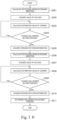
- Fig. 6 is a flowchart illustrating the motor adjustment method according to the embodiment of the present invention. Motor adjustment is performed by executing the processing of steps S101 to S109.
- Step S101 The energization control unit 122 causes the rotor 310 to rotate in the forward direction CW, and the rotational speed calculation unit 121 calculates the rotational speed of the rotor 310 on the basis of the change in the magnetic pole detected by the Hall sensor 330. The processing proceeds to step S102.
- Step S102 The forward rotation information acquisition unit 123 acquires the value of the current lin from the current detection unit 130. The processing proceeds to step S103.
- Step S103 The forward rotation information acquisition unit 123 determines whether or not to change the Hall sensor setting position.
- the processing returns to step S102.
- the forward rotation information acquisition unit 123 determines not to change the Hall sensor setting position (No in step S103)
- the processing proceeds to step S104.
- Step S104 The forward rotation information acquisition unit 123 creates the forward rotation information. The processing proceeds to step S105. Note that step S104 is an example of the "forward rotation information acquisition process".
- Step S105 The energization control unit 122 causes the rotor 310 to rotate in the reverse direction CCW, and the rotational speed calculation unit 121 calculates the rotational speed of the rotor 310 on the basis of the change in the magnetic pole detected by the Hall sensor 330. The processing proceeds to step S106.
- Step S106 The reverse rotation information acquisition unit 124 acquires the value of the current lin from the current detection unit 130. The processing proceeds to step S107.
- Step S107 The reverse rotation information acquisition unit 124 determines whether or not to change the Hall sensor setting position.
- the processing returns to step S106.
- the reverse rotation information acquisition unit 124 determines not to change the Hall sensor setting position (No in step S107)
- the processing proceeds to step S108.
- Step S108 The reverse rotation information acquisition unit 124 creates the reverse rotation information.
- the processing proceeds to step S109.
- step S108 is an example of the "reverse rotation information acquisition process".
- Step S109 The determination unit 125 determines the Hall sensor adjustment position on the basis of the forward rotation information and the reverse rotation information. The processing ends. Note that step S109 is an example of the "determination process".
- the motor adjustment method includes the forward rotation information acquisition process, the reverse rotation information acquisition process, and the determination process. Therefore, the motor M can be adjusted with high accuracy.
- FIG. 7 is a block diagram of the adjustment system 2200 according to the second embodiment of the present invention.
- the second embodiment is different from the first embodiment in the method of determining the Hall sensor adjustment position.
- differences from the first embodiment will be mainly described.
- the forward rotation information acquisition unit 123 acquires forward rotation information.
- the forward rotation information indicates a change in the value of the current lin flowing through the inverter circuit 110 at the time of the rotor 310 rotating in the forward direction CW when the Hall sensor setting position is scanned.
- the forward rotation information acquisition unit 123 performs polynomial approximation on the values of the plurality of currents lin to create forward rotation information.
- the forward rotation information is based on a forward rotation relational expression indicating a relationship between the value of the current lin and the Hall sensor setting position.
- the reverse rotation information acquisition unit 124 acquires reverse rotation information.
- the reverse rotation information indicates a change in the value of the current lin flowing through the inverter circuit 110 at the time of the rotor 310 rotating in the reverse CCW when the Hall sensor setting position is scanned.
- the reverse rotation information acquisition unit 124 performs polynomial approximation on the values of the plurality of currents lin to create reverse rotation information.
- the reverse rotation information is based on a reverse rotation relational expression indicating a relationship between the current value and the Hall sensor setting position.
- the determination unit 225 determines the Hall sensor setting position corresponding to the intersection of the forward rotation relational expression and the reverse rotation relational expression as the Hall sensor adjustment position. Therefore, the Hall sensor adjustment position can be determined with high accuracy.
- Fig. 8 is a diagram illustrating the current value with respect to the Hall sensor setting position.
- a horizontal axis represents the Hall sensor setting position.
- a vertical axis represents the value of the current lin.
- a round mark indicates the value of the current lin when the motor M rotates in the forward direction CW.
- a triangular mark indicates the value of the current lin when the motor M rotates in the reverse direction CCW.
- the Hall sensor adjustment position can be determined with high accuracy.
- FIG. 9 is a block diagram of the adjustment system 3200 according to the third embodiment of the present invention.
- the third embodiment is different from the first embodiment in that the control device 100 does not include the current detection unit 130.
- differences from the first embodiment will be mainly described.
- control unit 120 includes a voltage acquisition unit 326 and a current calculation unit 327.
- the voltage acquisition unit 326 acquires values Vs and Vc of the voltages applied to the inverter circuit 110. For example, the voltage acquisition unit 326 acquires the values Vs and Vc of the voltages determined by the user.
- the current calculation unit 327 calculates the estimation values of currents Is and Ic flowing through the motor M on the basis of the voltage values Vs and Vc and a rotational speed ⁇ , and calculates the estimation value of the current lin flowing through the inverter circuit 110 on the basis of Expression (1) from the estimation values of the currents Is and Ic flowing through the motor M and the voltage Vin applied to the inverter circuit 110.
- I in V s I s + V c I c V in
- the current calculation unit 327 calculates the estimation values Is and Ic of the current flowing through the motor M on the basis of Expression (2).
- V s V c R I s I c + ⁇ 0 L c ⁇ L s 0 I s I c + L s 0 0 L c d dt I s I c + K e ⁇ 1 0
- Vs and Vc are motor voltages
- Is and Ic are motor currents
- Vin is a power supply voltage
- lin is a power supply current
- R is a winding resistance
- Ls and Lc are winding inductances
- ⁇ is a rotational speed
- Ke is an induced voltage constant.
- the forward rotation information acquisition unit 123 acquires forward rotation information.
- the forward rotation information indicates a change in the estimation value lin of the current flowing through the inverter circuit 110 at the time of the rotor 310 rotating in the forward direction CW when the Hall sensor setting position is changed.
- the forward rotation information acquisition unit 123 creates the forward rotation information when the rotor 310 rotates at a predetermined speed for a predetermined period in the forward direction CW.
- the forward rotation information acquisition unit 123 calculates the estimation value lin of the current flowing through the inverter circuit 110 when the energization timing for each of the windings 322 of the plurality of phases is controlled.
- the forward rotation information acquisition unit 123 calculates the estimation value lin of the current flowing through the inverter circuit 110 when the energization timing for each of the windings 322 of the plurality of phases is controlled.
- the forward rotation information acquisition unit 123 calculates the estimation value lin of the current flowing through the inverter circuit 110 when the energization timing for each of the windings 322 of the plurality of phases is controlled.
- the value of the estimation value lin of the current may be an average value during a predetermined period or an intermediate value during the predetermined period.
- the reverse rotation information acquisition unit 124 acquires reverse rotation information.
- the reverse rotation information indicates a change in the estimation value lin of the current flowing through the inverter circuit 110 at the time of the rotor 310 rotating in the reverse CCW when the Hall sensor setting position is scanned.
- the reverse rotation information acquisition unit 124 creates the reverse rotation information when the rotor 310 rotates at a predetermined speed for a predetermined period in the reverse direction CCW.
- the reverse rotation information acquisition unit 124 calculates the estimation value lin of the current flowing through the inverter circuit 110 when the energization timing for each of the windings 322 of the plurality of phases is controlled.
- the reverse rotation information acquisition unit 124 calculates the estimation value lin of the current flowing through the inverter circuit 110 when the energization timing for each of the windings 322 of the plurality of phases is controlled.
- the reverse rotation information acquisition unit 124 calculates the estimation value lin of the current flowing through the inverter circuit 110 when the energization timing for each of the windings 322 of the plurality of phases is controlled.
- the value of the estimation value lin of the current may be an average value during a predetermined period or an intermediate value during the predetermined period.
- Fig. 10 is a flowchart illustrating the motor adjustment method according to the third embodiment. Motor adjustment is performed by executing the processing of steps S201 to S211.
- Step S201 The energization control unit 122 causes the rotor 310 to rotate in the forward direction CW, and the rotational speed calculation unit 121 calculates the rotational speed of the rotor 310 on the basis of the change in the magnetic pole detected by the Hall sensor 330.
- the processing proceeds to step S202.
- step S201 is an example of the "rotational speed calculation process”.
- Step S202 The voltage acquisition unit 326 acquires the values Vs and Vc of the voltages applied to the inverter circuit 110. The processing proceeds to step S203. Note that step S202 is an example of the "voltage acquisition process".
- Step S203 The current calculation unit 327 calculates the estimation values of the currents Is and Ic flowing to the motor M on the basis of the voltage values Vs and Vc and the rotational speed ⁇ , and calculates the estimation value lin of the current flowing to the inverter circuit 110 on the basis of the estimation values of the currents Is and Ic flowing to the motor M and the voltage Vin applied to the inverter circuit 110.
- the processing proceeds to step S204. Note that step S203 is an example of the "current calculation process".
- Step S204 The forward rotation information acquisition unit 123 determines whether or not to change the Hall sensor setting position.
- the processing returns to step S203.
- the forward rotation information acquisition unit 123 determines not to change the Hall sensor setting position (No in step S204)
- the processing proceeds to step S205.
- Step S205 The forward rotation information acquisition unit 123 acquires the forward rotation information. The processing proceeds to step S206. Note that step S205 is an example of the "forward rotation information acquisition process".
- Step S206 The energization control unit 122 causes the rotor 310 to rotate in the reverse direction CCW, and the rotational speed calculation unit 121 calculates the rotational speed of the rotor 310 on the basis of the change in the magnetic pole detected by the Hall sensor 330. The processing proceeds to step S207.
- Step S207 The voltage acquisition unit 326 acquires the values Vs and Vc of the voltages applied to the inverter circuit 110. The processing proceeds to step S208. Note that step S208 is an example of the "voltage acquisition process".
- Step S208 The current calculation unit 327 calculates the estimation values of the currents Is and Ic flowing to the motor M on the basis of the voltage values Vs and Vc and the rotational speed ⁇ , and calculates the estimation value lin of the current flowing to the inverter circuit 110 on the basis of the estimation values of the currents Is and Ic flowing to the motor M and the voltage Vin applied to the inverter circuit 110.
- the processing proceeds to step S209. Note that step S208 is an example of the "current calculation process".
- Step S209 The forward rotation information acquisition unit 123 determines whether or not to change the Hall sensor setting position.
- the processing returns to step S208.
- the forward rotation information acquisition unit 123 determines not to change the Hall sensor setting position (No in step S209), the processing proceeds to step S210.
- Step S210 The reverse rotation information acquisition unit 124 acquires the reverse rotation information. The processing proceeds to step S211. Note that step S210 is an example of the "reverse rotation information acquisition process".
- Step S211 The determination unit 125 determines the Hall sensor adjustment position on the basis of the forward rotation information and the reverse rotation information. The processing ends. Note that step S211 is an example of the "determination process".
- the motor M is connected to the control device 100 before shipment.
- the present invention is not limited thereto.
- the motor M and the control device 100 may be integrated.
- the control device 100 may adjust the Hall sensor setting position at a predetermined timing.
- the Hall sensor setting position can be adjusted at the time of aging deterioration or impact detection. Therefore, the motor M can always be used in an efficient state.
Landscapes
- Engineering & Computer Science (AREA)
- Power Engineering (AREA)
- Control Of Motors That Do Not Use Commutators (AREA)
Abstract
Description
- The present invention relates to a motor adjustment method.
- The brushless motor control device described in Patent Literature 1 includes an inverter circuit, a rotor magnetic pole detection unit, a rotor position estimation unit, a current detection unit, and an electrical angle correction unit. The inverter circuit rotates the motor in a forward direction. The electrical angle correction unit determines an electrical angle offset on the basis of the variation of a power supply current value, and corrects an estimated rotor position signal by adding the electrical angle offset to the electrical angle indicated by the estimated rotor position signal.
-
- Patent Literature 1:
WO 2018/79052 A - Summary of Invention
- However, the brushless motor control device described in Patent Literature 1 may not be able to calculate the electrical angle offset with high accuracy. As a result, the motor cannot be adjusted with high accuracy.
- The present invention has been made in view of the above problem, and an object thereof is to provide a motor adjustment method capable of adjusting a motor with high accuracy.
- An exemplary motor adjustment method of the present invention adjusts a motor driven by a control device. The motor includes a stator that has windings of a plurality of phases, a rotor that is rotatable with respect to the stator, and a Hall sensor that is arranged with a space from the rotor and detects a magnetic pole of the rotor. The control device includes a drive unit that applies a drive voltage to the windings of the plurality of phases, a rotational speed calculation unit that calculates a rotational speed of the rotor on a basis of a change in a magnetic pole detected by the Hall sensor, and an energization control unit that controls an energization timing for each of the windings of the plurality of phases on a basis of the rotational speed and a Hall sensor setting position. The motor adjustment method includes: acquiring forward rotation information indicating a change in a value of a current flowing through the drive unit at time of the rotor rotating in a forward direction when the Hall sensor setting position is changed; acquiring reverse rotation information indicating a change in a value of a current flowing through the drive unit at time of the rotor rotating in a reverse direction when the Hall sensor setting position is changed; and determining a Hall sensor adjustment position on a basis of the forward rotation information and the reverse rotation information. The Hall sensor adjustment position indicates a position obtained by adding a correction amount to the Hall sensor setting position.
- According to the invention, the motor can be adjusted with high accuracy.
-
-
Fig. 1 is a block diagram of a control device according to a first embodiment of the present invention. -
Fig. 2 is a circuit diagram illustrating an inverter circuit. -
Fig. 3 is a schematic diagram illustrating a motor. -
Fig. 4 is a diagram illustrating a counter electromotive force and a Hall sensor signal. -
Fig. 5 is a diagram illustrating an absolute value of a difference of current values with respect to a Hall sensor setting position. -
Fig. 6 is a flowchart illustrating a motor adjustment method according to the first embodiment. -
Fig. 7 is a block diagram of a control device according to a second embodiment of the present invention. -
Fig. 8 is a diagram illustrating the current value with respect to the Hall sensor setting position. -
Fig. 9 is a block diagram of a control device according to a third embodiment of the present invention. -
Fig. 10 is a flowchart illustrating a motor adjustment method according to the third embodiment. - Hereinafter, exemplary embodiments of the present invention will be described with reference to the drawings. In the drawings, the same or corresponding portions are denoted by the same reference signs and description thereof will not be repeated.
- With reference to
Fig. 1 , anadjustment system 200 according to an embodiment of the present invention will be described.Fig. 1 is a block diagram of theadjustment system 200 according to the embodiment of the present invention. - As illustrated in
Fig. 1 , theadjustment system 200 includes acontrol device 100 and a DC power supply unit B. A motor M is connected to thecontrol device 100. For example, the motor M before shipment is connected to thecontrol device 100. The motor M is, for example, a brushless DC motor. The motor M has a U phase, a V phase, and a W phase. The motor M is driven by thecontrol device 100. - The DC power supply unit B applies a voltage. For example, the DC power supply unit B applies a voltage of a predetermined value. The predetermined value is determined by a user, for example.
- The
control device 100 adjusts the motor M. Specifically, thecontrol device 100 adjusts the driving of the motor M. More specifically, thecontrol device 100 adjusts a Hall sensor setting position to be described later. Thecontrol device 100 includes aninverter circuit 110, acontrol unit 120, and acurrent detection unit 130. Theinverter circuit 110 is an example of a "drive unit". - The
current detection unit 130 detects a current lin flowing through theinverter circuit 110. Thecurrent detection unit 130 outputs the detection result to thecontrol unit 120. As a result, thecontrol unit 120 can accurately acquire the current lin flowing through theinverter circuit 110. - The
control device 100 outputs three-phase AC power. Thecontrol device 100 includes threeoutput terminals 102. The threeoutput terminals 102 include anoutput terminal 102u, anoutput terminal 102v, and anoutput terminal 102w. The threeoutput terminals 102 output a three-phase output voltage and a three-phase output current to the motor M. Specifically, anoutput terminal 102u outputs a U-phase output voltage Vu and a U-phase output current Iu to the motor M. Anoutput terminal 102v outputs a V-phase output voltage Vv and a V-phase output current Iv to the motor M. Anoutput terminal 102w outputs a W-phase output voltage Vw and a W-phase output current Iw to the motor M. - Next, the
inverter circuit 110 will be described with reference toFig. 2. Fig. 2 is a circuit diagram illustrating theinverter circuit 110. As illustrated inFig. 2 , theinverter circuit 110 applies a drive voltage to the windings of the plurality of phases. - The
inverter circuit 110 includes a first power supply terminal P, a second power supply terminal N, a capacitor C, and threeseries bodies 112. - A first voltage V1 is applied to the first power supply terminal P. The first power supply terminal P is connected to a DC voltage source B.
- A second voltage V2 is applied to the second power supply terminal N. The second power supply terminal N is connected to the DC voltage source B. The second voltage V2 is lower than the first voltage V1.
- The capacitor C is connected between the first power supply terminal P and the second power supply terminal N.
- The three
serial bodies 112 include aseries body 112u, aseries body 112v, and aseries body 112w. The threeseries bodies 112 are connected in parallel to each other. One end of each of the threeseries bodies 112 is connected to the first power supply terminal P. The other end of each of the threeseries bodies 112 is connected to the second power supply terminal N. - In each of the three
series bodies 112, two semiconductor switching elements are connected in series. The semiconductor switching element is, for example, an insulated gate bipolar transistor (IGBT). Note that the semiconductor switching element may be another transistor such as a field effect transistor. A rectifier element D is connected in parallel to each of these semiconductor switching elements with the first power supply terminal P side (the upper side in the drawing) as a cathode and the second power supply terminal N side (the lower side in the drawing) as an anode. In a case where a field effect transistor is used as the semiconductor switching element, a parasitic diode may be used as the rectifier element. - Each of the three
series bodies 112 includes a first semiconductor switching element and a second semiconductor switching element. Specifically, theseries body 112u includes a first semiconductor switching element Up and a second semiconductor switching element Un. Theseries body 112v includes a first semiconductor switching element Vp and a second semiconductor switching element Vn. Theseries body 112w includes a first semiconductor switching element Wp and a second semiconductor switching element Wn. - The first semiconductor switching element Up, the first semiconductor switching element Vp, and the first semiconductor switching element Wp are connected to the first power supply terminal P. In other words, the first semiconductor switching element Up, the first semiconductor switching element Vp, and the first semiconductor switching element Wp are semiconductor switching elements on a high voltage side.
- The second semiconductor switching element Un, the second semiconductor switching element Vn, and the second semiconductor switching element Wn are connected to the second power supply terminal N. In other words, the second semiconductor switching element Un, the second semiconductor switching element Vn, and the second semiconductor switching element Wn are semiconductor switching elements on a low voltage side.
- The first semiconductor switching element and the second semiconductor switching element are connected at a
connection point 114. Specifically, the first semiconductor switching element Up and the second semiconductor switching element Un are connected at aconnection point 114u. The first semiconductor switching element Vp and the second semiconductor switching element Vn are connected at a connection point 114v. The first semiconductor switching element Wp and the second semiconductor switching element Wn are connected at a connection point 114w. - The
connection point 114 in each of the threeseries bodies 112 is connected to the threeoutput terminals 102. Specifically, theconnection point 114u of theseries body 112u is connected to theoutput terminal 102u. The connection point 114v in theseries body 112v is connected to theoutput terminal 102v. The connection point 114w in theseries body 112w is connected to theoutput terminal 102w. - A PWM signal is input to the first semiconductor switching element Up, the first semiconductor switching element Vp, and the first semiconductor switching element Wp. The PWM signal is output from the
control unit 120. Hereinafter, in the present specification, the PWM signal input to the first semiconductor switching element Up may be referred to as an "UpPWM signal". The PWM signal input to the first semiconductor switching element Vp may be referred to as a "VpPWM signal". The PWM signal input to the first semiconductor switching element Wp may be referred to as a "WpPWM signal". The first semiconductor switching element Up, the first semiconductor switching element Vp, and the first semiconductor switching element Wp are switched on and off at a frequency higher than the frequency of an AC output. For example, the first semiconductor switching element Up, the first semiconductor switching element Vp, and the first semiconductor switching element Wp are turned on in a case where the UpPWM signal, the VpPWM signal, and the WpPWM signal are at a HIGH level, respectively. On the other hand, the first semiconductor switching element Up, the first semiconductor switching element Vp, and the first semiconductor switching element Wp are turned off in a case where the UpPWM signal, the VpPWM signal, and the WpPWM signal are at a LOW level, respectively. - A PWM signal is input to the second semiconductor switching element Un, the second semiconductor switching element Vn, and the second semiconductor switching element Wn. The PWM signal is output from the
control unit 120. Hereinafter, in the present specification, the PWM signal input to the second semiconductor switching element Un may be referred to as an "UnPWM signal". In addition, the PWM signal input to the second semiconductor switching element Vn may be referred to as a "VnPWM signal". The PWM signal input to the second semiconductor switching element Wn may be referred to as a "WnPWM signal". The second semiconductor switching element Un, the second semiconductor switching element Vn, and the second semiconductor switching element Wn are switched on and off at a frequency higher than the frequency of an AC output. For example, the second semiconductor switching element Un, the second semiconductor switching element Vn, and the second semiconductor switching element Wn are turned on in a case where the UnPWM signal, the VnPWM signal, and the WnPWM signal are at a HIGH level, respectively. On the other hand, the second semiconductor switching element Un, the second semiconductor switching element Vn, and the second semiconductor switching element Wn are turned off in a case where the UnPWM signal, the VnPWM signal, and the WnPWM signal are at a LOW level, respectively. - Next, the motor M will be described with reference to
Fig. 3. Fig. 3 is a schematic diagram illustrating the motor M. As illustrated inFig. 3 , the motor M includes arotor 310, astator 320, and three Hall sensors 330. - The
rotor 310 is arranged about a central axis AX extending in a horizontal direction. That is, as an example, the motor M is an inner rotor type motor. Therotor 310 rotates about the central axis AX. Therotor 310 is arranged on the inner side of thestator 320 in a radial direction RD. Therotor 310 is rotatable with respect to thestator 320. - The
stator 320 is arranged about the central axis AX extending in the horizontal direction. Thestator 320 faces therotor 310 in the radial direction RD. Thestator 320 haswindings 322 of a plurality of phases. In the present embodiment, thestator 320 has three-phase windings 322. - The three Hall sensors 330 include a Hall sensor 332, a Hall sensor 334, and a Hall sensor 336. The Hall sensor 332 is a U-phase Hall sensor. The Hall sensor 334 is a V-phase Hall sensor. The Hall sensor 336 is a W-phase Hall sensor. The Hall sensor 330 is, for example, a magnetic sensor. The Hall sensor 330 is arranged with a space from the
rotor 310 and detects the magnetic pole of therotor 310. The Hall sensor 330 is arranged in the vicinity of therotor 310. In the present embodiment, the Hall sensor 330 is arranged on thestator 320. The Hall sensor 330 outputs a detection result (for example, a change in magnetic pole) to thecontrol unit 120. - As illustrated in
Fig. 1 , thecontrol unit 120 is a hardware circuit including a processor such as a central processing unit (CPU), an application specific integrated circuit (ASIC), and the like. Then, the processor of thecontrol unit 120 executes the motor control software stored in a storage device. Thecontrol unit 120 includes a rotationalspeed calculation unit 121 and anenergization control unit 122. - The
control unit 120 controls theinverter circuit 110. Specifically, thecontrol unit 120 controls theinverter circuit 110 by generating a PWM signal and outputting the PWM signal. More specifically, thecontrol unit 120 generates a PWM signal to be input to each of the threeseries bodies 112. - The rotational
speed calculation unit 121 calculates the rotational speed of therotor 310 on the basis of the change in the magnetic pole detected by the Hall sensor 330. In addition, the rotationalspeed calculation unit 121 calculates the rotational speed of therotor 310 with respect to thestator 320 on the basis of the rotational position of therotor 310. - The
energization control unit 122 controls an energization timing for each of thewindings 322 of the plurality of phases on the basis of the rotational speed and the Hall sensor setting position. The Hall sensor setting position indicates the setting position of the Hall sensor 330 on the motor control software with respect to the winding 322 of each phase. - Incidentally, in general, when the motor M is manufactured, an attachment error (positional deviation) occurs between the design position of the Hall sensor 330 with respect to the winding 322 of each phase and the actual position of the Hall sensor 330 with respect to the winding 322 of each phase. The positional deviation will be described with reference to
Fig. 4. Fig. 4 is a diagram illustrating a counter electromotive force and a Hall sensor signal. InFig. 4 , theenergization control unit 122 controls the energization timing for each of thewindings 322 of the plurality of phases on the basis of the position of the Hall sensor 330 on the motor control software with respect to the winding 322 of each phase. - As illustrated in
Fig. 4 , the waveform of the counter electromotive force has a sinusoidal wave shape. The position of the winding 322 of thestator 320 corresponds to the waveform of the counter electromotive force. The Hall sensor signal has a rectangular wave shape. - α is a value determined by a positional relationship between the position of the winding 322 of the
stator 320 and the Hall sensor 330. A deviation +Δα occurs in the Hall sensor signal due to an attachment error between the winding 322 of thestator 320 and the Hall sensor 330. - The
control unit 120 further includes a forward rotationinformation acquisition unit 123, a reverse rotationinformation acquisition unit 124, and adetermination unit 125. - The forward rotation
information acquisition unit 123 acquires forward rotation information. The forward rotation information indicates a change in the value of the current lin flowing through theinverter circuit 110 at the time of therotor 310 rotating in a forward direction CW when the Hall sensor setting position is changed. The forward direction CW is, for example, clockwise. Specifically, the forward rotationinformation acquisition unit 123 creates the forward rotation information when therotor 310 rotates at a predetermined speed for a predetermined period in the forward direction CW. The predetermined speed may be, for example, a rotational speed at which the motor M is used after shipment, or may be a maximum rotational speed of the motor M. The predetermined period is, for example, an arbitrary period determined by the user, and is a period in which the rotational speed of the motor M is stabilized. - Specifically, assuming that the Hall sensor setting position is a first Hall sensor setting position, the forward rotation
information acquisition unit 123 acquires the value of the current lin flowing through theinverter circuit 110 when the energization timing for each of thewindings 322 of the plurality of phases is controlled. The first Hall sensor setting position indicates, for example, the design position (for example, θ degrees) of the Hall sensor 330 with respect to the winding 322 of each phase. - Next, assuming that the Hall sensor setting position is a second Hall sensor setting position, the forward rotation
information acquisition unit 123 acquires the value of the current lin flowing through theinverter circuit 110 when the energization timing for each of thewindings 322 of the plurality of phases is controlled. The second Hall sensor setting position indicates a position (for example, θ+0.1 degrees) obtained by adding a predetermined amount (for example, 0.1 degrees) to the first Hall sensor setting position. The predetermined amount is arbitrarily determined by the user, for example. - Next, assuming that the Hall sensor setting position is a third Hall sensor setting position, the forward rotation
information acquisition unit 123 acquires the value of the current lin flowing through theinverter circuit 110 when the energization timing for each of thewindings 322 of the plurality of phases is controlled. The third Hall sensor setting position indicates a position (for example, θ-0.1 degrees) obtained by adding a predetermined amount (for example, -0.1 degrees) to the first Hall sensor setting position. - Similarly, for example, assuming that the Hall sensor setting position is a fourth Hall sensor setting position, a fifth Hall sensor setting position, a sixth Hall sensor setting position, a seventh Hall sensor setting position, an eighth Hall sensor setting position, or a ninth Hall sensor setting position, the forward rotation
information acquisition unit 123 acquires the value of the current lin flowing through theinverter circuit 110. The fourth Hall sensor setting position indicates a position (for example, θ+0.2 degrees) obtained by adding a predetermined amount (for example, 0.2 degrees) to the first Hall sensor setting position. The fifth Hall sensor setting position indicates a position (for example, θ-0.2 degrees) obtained by adding a predetermined amount (for example, -0.2 degrees) to the first Hall sensor setting position. The sixth Hall sensor setting position indicates a position (for example, θ+0.3 degrees) obtained by adding a predetermined amount (for example, 0.3 degrees) to the first Hall sensor setting position. The seventh Hall sensor setting position indicates a position (for example, θ-0.3 degrees) obtained by adding a predetermined amount (for example, -0.3 degrees) to the first Hall sensor setting position. The eighth Hall sensor setting position indicates a position (for example, θ+0.4 degrees) obtained by adding a predetermined amount (for example, 0.4 degrees) to the first Hall sensor setting position. The ninth Hall sensor setting position indicates a position (for example, θ-0.4 degrees) obtained by adding a predetermined amount (for example, -0.4 degrees) to the first Hall sensor setting position. Note that the value of the current lin may be an average value during a predetermined period or an intermediate value during the predetermined period. - The reverse rotation
information acquisition unit 124 acquires reverse rotation information. The reverse rotation information indicates a change in the value of the current lin flowing through theinverter circuit 110 at the time of therotor 310 rotating in a reverse direction CCW when the Hall sensor setting position is changed. The reverse direction CCW is, for example, counterclockwise. Specifically, the reverse rotationinformation acquisition unit 124 creates the reverse rotation information when therotor 310 rotates at a predetermined speed for a predetermined period in the reverse direction CCW. - Specifically, assuming that the Hall sensor setting position is the first Hall sensor setting position, the reverse rotation
information acquisition unit 124 acquires the value of the current lin flowing through theinverter circuit 110 when the energization timing for each of thewindings 322 of the plurality of phases is controlled. - Next, assuming that the Hall sensor setting position is the second Hall sensor setting position, the reverse rotation
information acquisition unit 124 acquires the value of the current lin flowing through theinverter circuit 110 when the energization timing for each of thewindings 322 of the plurality of phases is controlled. - Next, assuming that the Hall sensor setting position is the third Hall sensor setting position, the reverse rotation
information acquisition unit 124 acquires the value of the current lin flowing through theinverter circuit 110 when the energization timing for each of thewindings 322 of the plurality of phases is controlled. - Similarly, assuming that the Hall sensor setting position is the fourth Hall sensor setting position, the fifth Hall sensor setting position, the sixth Hall sensor setting position, the seventh Hall sensor setting position, the eighth Hall sensor setting position, and the ninth Hall sensor setting position, the reverse rotation
information acquisition unit 124 acquires the value of the current lin flowing through theinverter circuit 110. Note that the value of the current lin may be an average value during a predetermined period or an intermediate value during the predetermined period. - The
determination unit 125 determines the Hall sensor adjustment position on the basis of the forward rotation information and the reverse rotation information. The Hall sensor adjustment position indicates a position obtained by adding a correction amount to the Hall sensor setting position. As a result, thedetermination unit 125 determines the correction amount by using both the forward rotation information and the reverse rotation information as compared with the case of using either the forward rotation information or the reverse rotation information. Therefore, the motor M can be adjusted with high accuracy. Note that thedetermination unit 125 may calculate the Hall sensor adjustment position or may calculate the correction amount. - Specifically, the
determination unit 125 determines the Hall sensor setting position with a smallest difference value among the plurality of Hall sensor setting positions as the Hall sensor adjustment position. The difference value indicates the absolute value of a difference between the value of the current lin when therotor 310 rotates in the forward direction CW and the value of the current lin when therotor 310 rotates in the reverse direction CCW, at the same Hall sensor setting position. Therefore, the adjustment position of the Hall sensor can be easily determined without complicated calculation. - For example, assuming that the Hall sensor setting position is the first Hall sensor setting position, the
determination unit 125 calculates the absolute value of the difference between the value of the current lin when therotor 310 rotates in the forward direction CW and the value of the current lin when therotor 310 rotates in the reverse direction CCW. In addition, assuming that the Hall sensor setting position is the second Hall sensor setting position, thedetermination unit 125 calculates the absolute value of the difference between the value of the current lin when therotor 310 rotates in the forward direction CW and the value of the current lin when therotor 310 rotates in the reverse direction CCW. As described above, thedetermination unit 125 calculates the absolute value of the difference between the value of the current lin when therotor 310 rotates in the forward direction CW and the value of the current lin when therotor 310 rotates in the reverse direction CCW. - Next, a determination method for determining the Hall sensor adjustment position will be described with reference to
Fig. 5. Fig. 5 is a diagram illustrating the absolute value of a difference of current values with respect to the Hall sensor setting position. InFig. 5 , a horizontal axis represents the Hall sensor setting position. A vertical axis represents the absolute value of the difference between the value of the current lin when the motor M rotates in the forward direction CW and the value of the current lin when the motor M rotates in the reverse direction CCW. - As illustrated in
Fig. 5 , when a Hall sensor installation position is at the electrical angle θ+0.1 degrees, the absolute value of the difference between the current values is minimum. Thedetermination unit 125 sets a position (electrical angle θ + 0.1 degrees) at which the absolute value of the difference between the current values is minimum as the Hall sensor adjustment position. Therefore, the adjustment position of the Hall sensor can be easily determined without complicated calculation. - Next, a motor adjustment method according to the embodiment of the present invention will be described with reference to
Fig. 6. Fig. 6 is a flowchart illustrating the motor adjustment method according to the embodiment of the present invention. Motor adjustment is performed by executing the processing of steps S101 to S109. - Step S101: The
energization control unit 122 causes therotor 310 to rotate in the forward direction CW, and the rotationalspeed calculation unit 121 calculates the rotational speed of therotor 310 on the basis of the change in the magnetic pole detected by the Hall sensor 330. The processing proceeds to step S102. - Step S102: The forward rotation
information acquisition unit 123 acquires the value of the current lin from thecurrent detection unit 130. The processing proceeds to step S103. - Step S103: The forward rotation
information acquisition unit 123 determines whether or not to change the Hall sensor setting position. When the forward rotationinformation acquisition unit 123 determines to change the Hall sensor setting position (Yes in step S103), the processing returns to step S102. On the other hand, when the forward rotationinformation acquisition unit 123 determines not to change the Hall sensor setting position (No in step S103), the processing proceeds to step S104. - Step S104: The forward rotation
information acquisition unit 123 creates the forward rotation information. The processing proceeds to step S105. Note that step S104 is an example of the "forward rotation information acquisition process". - Step S105: The
energization control unit 122 causes therotor 310 to rotate in the reverse direction CCW, and the rotationalspeed calculation unit 121 calculates the rotational speed of therotor 310 on the basis of the change in the magnetic pole detected by the Hall sensor 330. The processing proceeds to step S106. - Step S106: The reverse rotation
information acquisition unit 124 acquires the value of the current lin from thecurrent detection unit 130. The processing proceeds to step S107. - Step S107: The reverse rotation
information acquisition unit 124 determines whether or not to change the Hall sensor setting position. When the reverse rotationinformation acquisition unit 124 determines to change the Hall sensor setting position (Yes in step S107), the processing returns to step S106. On the other hand, when the reverse rotationinformation acquisition unit 124 determines not to change the Hall sensor setting position (No in step S107), the processing proceeds to step S108. - Step S108: The reverse rotation
information acquisition unit 124 creates the reverse rotation information. The processing proceeds to step S109. Note that step S108 is an example of the "reverse rotation information acquisition process". - Step S109: The
determination unit 125 determines the Hall sensor adjustment position on the basis of the forward rotation information and the reverse rotation information. The processing ends. Note that step S109 is an example of the "determination process". - As described above with reference to
Fig. 6 , the motor adjustment method includes the forward rotation information acquisition process, the reverse rotation information acquisition process, and the determination process. Therefore, the motor M can be adjusted with high accuracy. - An
adjustment system 2200 according to a second embodiment of the present invention will be described with reference toFig. 7. Fig. 7 is a block diagram of theadjustment system 2200 according to the second embodiment of the present invention. The second embodiment is different from the first embodiment in the method of determining the Hall sensor adjustment position. Hereinafter, differences from the first embodiment will be mainly described. - The forward rotation
information acquisition unit 123 acquires forward rotation information. The forward rotation information indicates a change in the value of the current lin flowing through theinverter circuit 110 at the time of therotor 310 rotating in the forward direction CW when the Hall sensor setting position is scanned. For example, the forward rotationinformation acquisition unit 123 performs polynomial approximation on the values of the plurality of currents lin to create forward rotation information. The forward rotation information is based on a forward rotation relational expression indicating a relationship between the value of the current lin and the Hall sensor setting position. - The reverse rotation
information acquisition unit 124 acquires reverse rotation information. The reverse rotation information indicates a change in the value of the current lin flowing through theinverter circuit 110 at the time of therotor 310 rotating in the reverse CCW when the Hall sensor setting position is scanned. The reverse rotationinformation acquisition unit 124 performs polynomial approximation on the values of the plurality of currents lin to create reverse rotation information. The reverse rotation information is based on a reverse rotation relational expression indicating a relationship between the current value and the Hall sensor setting position. - The
determination unit 225 determines the Hall sensor setting position corresponding to the intersection of the forward rotation relational expression and the reverse rotation relational expression as the Hall sensor adjustment position. Therefore, the Hall sensor adjustment position can be determined with high accuracy. - Next, the determination method for determining the Hall sensor adjustment position will be described with reference to
Fig. 8. Fig. 8 is a diagram illustrating the current value with respect to the Hall sensor setting position. InFig. 8 , a horizontal axis represents the Hall sensor setting position. A vertical axis represents the value of the current lin. A round mark indicates the value of the current lin when the motor M rotates in the forward direction CW. A triangular mark indicates the value of the current lin when the motor M rotates in the reverse direction CCW. - As illustrated in
Fig. 8 , when the Hall sensor installation position is at an electrical angle θ' degrees, the forward rotation relational expression and the reverse rotation relational expression intersect each other. Thedetermination unit 225 sets, as the Hall sensor adjustment position, a position (electrical angle θ' degrees) at which the forward rotation relational expression and the reverse rotation relational expression intersect each other. Therefore, the Hall sensor adjustment position can be determined with high accuracy. - An
adjustment system 3200 according to a third embodiment of the present invention will be described.Fig. 9 is a block diagram of theadjustment system 3200 according to the third embodiment of the present invention. The third embodiment is different from the first embodiment in that thecontrol device 100 does not include thecurrent detection unit 130. Hereinafter, differences from the first embodiment will be mainly described. - As illustrated in
Fig. 9 , thecontrol unit 120 includes avoltage acquisition unit 326 and acurrent calculation unit 327. - The
voltage acquisition unit 326 acquires values Vs and Vc of the voltages applied to theinverter circuit 110. For example, thevoltage acquisition unit 326 acquires the values Vs and Vc of the voltages determined by the user. - The
current calculation unit 327 calculates the estimation values of currents Is and Ic flowing through the motor M on the basis of the voltage values Vs and Vc and a rotational speed ω, and calculates the estimation value of the current lin flowing through theinverter circuit 110 on the basis of Expression (1) from the estimation values of the currents Is and Ic flowing through the motor M and the voltage Vin applied to theinverter circuit 110. As a result, it is not necessary to provide thecurrent detection unit 130, and it is possible to suppress an increase in size of the circuit.
[Math. 1]
- Here, for example, the
current calculation unit 327 calculates the estimation values Is and Ic of the current flowing through the motor M on the basis of Expression (2).
[Math. 2]
- Note that Vs and Vc are motor voltages, Is and Ic are motor currents, Vin is a power supply voltage, lin is a power supply current, R is a winding resistance, Ls and Lc are winding inductances, ω is a rotational speed, and Ke is an induced voltage constant.
- The forward rotation
information acquisition unit 123 acquires forward rotation information. The forward rotation information indicates a change in the estimation value lin of the current flowing through theinverter circuit 110 at the time of therotor 310 rotating in the forward direction CW when the Hall sensor setting position is changed. Specifically, the forward rotationinformation acquisition unit 123 creates the forward rotation information when therotor 310 rotates at a predetermined speed for a predetermined period in the forward direction CW. - Specifically, assuming that the Hall sensor setting position is the first Hall sensor setting position, the forward rotation
information acquisition unit 123 calculates the estimation value lin of the current flowing through theinverter circuit 110 when the energization timing for each of thewindings 322 of the plurality of phases is controlled. Next, assuming that the Hall sensor setting position is the second Hall sensor setting position, the forward rotationinformation acquisition unit 123 calculates the estimation value lin of the current flowing through theinverter circuit 110 when the energization timing for each of thewindings 322 of the plurality of phases is controlled. - Next, assuming that the Hall sensor setting position is the third Hall sensor setting position, the forward rotation
information acquisition unit 123 calculates the estimation value lin of the current flowing through theinverter circuit 110 when the energization timing for each of thewindings 322 of the plurality of phases is controlled. Note that the value of the estimation value lin of the current may be an average value during a predetermined period or an intermediate value during the predetermined period. - The reverse rotation
information acquisition unit 124 acquires reverse rotation information. The reverse rotation information indicates a change in the estimation value lin of the current flowing through theinverter circuit 110 at the time of therotor 310 rotating in the reverse CCW when the Hall sensor setting position is scanned. Specifically, the reverse rotationinformation acquisition unit 124 creates the reverse rotation information when therotor 310 rotates at a predetermined speed for a predetermined period in the reverse direction CCW. - Specifically, assuming that the Hall sensor setting position is the first Hall sensor setting position, the reverse rotation
information acquisition unit 124 calculates the estimation value lin of the current flowing through theinverter circuit 110 when the energization timing for each of thewindings 322 of the plurality of phases is controlled. Next, assuming that the Hall sensor setting position is the second Hall sensor setting position, the reverse rotationinformation acquisition unit 124 calculates the estimation value lin of the current flowing through theinverter circuit 110 when the energization timing for each of thewindings 322 of the plurality of phases is controlled. - Next, assuming that the Hall sensor setting position is the third Hall sensor setting position, the reverse rotation
information acquisition unit 124 calculates the estimation value lin of the current flowing through theinverter circuit 110 when the energization timing for each of thewindings 322 of the plurality of phases is controlled. Note that the value of the estimation value lin of the current may be an average value during a predetermined period or an intermediate value during the predetermined period. - Next, a motor adjustment method according to the third embodiment will be described with reference to
Fig. 10. Fig. 10 is a flowchart illustrating the motor adjustment method according to the third embodiment. Motor adjustment is performed by executing the processing of steps S201 to S211. - Step S201: The
energization control unit 122 causes therotor 310 to rotate in the forward direction CW, and the rotationalspeed calculation unit 121 calculates the rotational speed of therotor 310 on the basis of the change in the magnetic pole detected by the Hall sensor 330. The processing proceeds to step S202. Note that step S201 is an example of the "rotational speed calculation process". - Step S202: The
voltage acquisition unit 326 acquires the values Vs and Vc of the voltages applied to theinverter circuit 110. The processing proceeds to step S203. Note that step S202 is an example of the "voltage acquisition process". - Step S203: The
current calculation unit 327 calculates the estimation values of the currents Is and Ic flowing to the motor M on the basis of the voltage values Vs and Vc and the rotational speed ω, and calculates the estimation value lin of the current flowing to theinverter circuit 110 on the basis of the estimation values of the currents Is and Ic flowing to the motor M and the voltage Vin applied to theinverter circuit 110. The processing proceeds to step S204. Note that step S203 is an example of the "current calculation process". - Step S204: The forward rotation
information acquisition unit 123 determines whether or not to change the Hall sensor setting position. When the forward rotationinformation acquisition unit 123 determines to change the Hall sensor setting position (Yes in step S204), the processing returns to step S203. On the other hand, when the forward rotationinformation acquisition unit 123 determines not to change the Hall sensor setting position (No in step S204), the processing proceeds to step S205. - Step S205: The forward rotation
information acquisition unit 123 acquires the forward rotation information. The processing proceeds to step S206. Note that step S205 is an example of the "forward rotation information acquisition process". - Step S206: The
energization control unit 122 causes therotor 310 to rotate in the reverse direction CCW, and the rotationalspeed calculation unit 121 calculates the rotational speed of therotor 310 on the basis of the change in the magnetic pole detected by the Hall sensor 330. The processing proceeds to step S207. - Step S207: The
voltage acquisition unit 326 acquires the values Vs and Vc of the voltages applied to theinverter circuit 110. The processing proceeds to step S208. Note that step S208 is an example of the "voltage acquisition process". - Step S208: The
current calculation unit 327 calculates the estimation values of the currents Is and Ic flowing to the motor M on the basis of the voltage values Vs and Vc and the rotational speed ω, and calculates the estimation value lin of the current flowing to theinverter circuit 110 on the basis of the estimation values of the currents Is and Ic flowing to the motor M and the voltage Vin applied to theinverter circuit 110. The processing proceeds to step S209. Note that step S208 is an example of the "current calculation process". - Step S209: The forward rotation
information acquisition unit 123 determines whether or not to change the Hall sensor setting position. When the forward rotationinformation acquisition unit 123 determines to change the Hall sensor setting position (Yes in step S209), the processing returns to step S208. On the other hand, when the forward rotationinformation acquisition unit 123 determines not to change the Hall sensor setting position (No in step S209), the processing proceeds to step S210. - Step S210: The reverse rotation
information acquisition unit 124 acquires the reverse rotation information. The processing proceeds to step S211. Note that step S210 is an example of the "reverse rotation information acquisition process". - Step S211: The
determination unit 125 determines the Hall sensor adjustment position on the basis of the forward rotation information and the reverse rotation information. The processing ends. Note that step S211 is an example of the "determination process". - The embodiments of the present invention have been described above with reference to the drawings (
Figs. 1 to 10 ). It should be noted that the present invention is not limited to the above-described embodiments and is implementable in various forms within a range not departing from the scope of the present invention. For easy understanding, the drawings schematically illustrate each component as the subject, and the thickness, length, number, and the like of each illustrated constituent element are different from actual ones for convenience of drawing. Additionally, the material, shape, dimension, and the like of each component illustrated in the above-described embodiments are mere examples and are not particularly limited, and various modifications can be made without substantially departing from the effects of the present invention. - As described with reference to
Figs. 1 to 10 , in the first to third embodiments, the motor M is connected to thecontrol device 100 before shipment. However, the present invention is not limited thereto. The motor M and thecontrol device 100 may be integrated. Then, thecontrol device 100 may adjust the Hall sensor setting position at a predetermined timing. As a result, the Hall sensor setting position can be adjusted at the time of aging deterioration or impact detection. Therefore, the motor M can always be used in an efficient state. -
- 100
- control device
- 110
- inverter circuit (drive unit)
- 121
- rotational speed calculation unit
- 122
- energization control unit
- M
- motor
Claims (5)
- A motor adjustment method for adjusting a motor (M) driven by a control device (100), whereinthe motor (M) includes:a stator (320) that has windings of a plurality of phases,a rotor (310) that is rotatable with respect to the stator (320), anda Hall sensor (330) that is arranged with a space from the rotor (310) and detects a magnetic pole of the rotor (310), andthe control device (100) includes:a drive unit (110) that applies a drive voltage to the windings of the plurality of phases,a rotational speed calculation unit (121) that calculates a rotational speed of the rotor (310) on a basis of a change in a magnetic pole detected by the Hall sensor (330), andan energization control unit (122) that controls an energization timing for each of the windings of the plurality of phases on a basis of the rotational speed and a Hall sensor setting position,the motor adjustment method comprising:acquiring forward rotation information indicating a change in a value of a current flowing through the drive unit (110) at time of the rotor (310) rotating in a forward direction when the Hall sensor setting position is changed;acquiring reverse rotation information indicating a change in a value of a current flowing through the drive unit (110) at time of the rotor (310) rotating in a reverse direction when the Hall sensor setting position is changed; anddetermining a Hall sensor adjustment position on a basis of the forward rotation information and the reverse rotation information, whereinthe Hall sensor adjustment position indicates a position obtained by adding a correction amount to the Hall sensor setting position.
- The motor adjustment method according to claim 1, whereinin the determining, the Hall sensor setting position with a smallest difference value among a plurality of the Hall sensor setting positions is determined as the Hall sensor adjustment position, andthe difference value indicates an absolute value of a difference between a value of the current when the rotor (310) rotates in the forward direction and a value of the current when the rotor (310) rotates in the reverse direction, at a same Hall sensor setting position.
- The motor adjustment method according to claim 1, whereinin the acquiring the forward rotation information, the forward rotation information is acquired by scanning the Hall sensor setting position,in the acquiring the reverse rotation information, the reverse rotation information is acquired by scanning the Hall sensor setting position,the forward rotation information is based on a forward rotation relational expression indicating a relationship between the value of the current and the Hall sensor setting position,the reverse rotation information is based on a reverse rotation relational expression indicating a relationship between the value of the current and the Hall sensor setting position, andin the determining, the Hall sensor setting position corresponding to an intersection of the forward rotation relational expression and the reverse rotation relational expression is determined as the Hall sensor adjustment position.
- The motor adjustment method according to any one of claims 1 to 3, further comprising:calculating a rotational speed of the rotor (310) on a basis of a change in a magnetic pole of the rotor (310) detected by the Hall sensor (330);acquiring a value of a voltage applied to the drive unit (110); andcalculating the value of the current flowing through the drive unit (110) on a basis of the value of the voltage and the rotational speed.
- The motor adjustment method according to any one of claims 1 to 3, wherein the control device (100) further includes a current detection unit (130) that detects the value of the current flowing through the drive unit (110).
Applications Claiming Priority (1)
| Application Number | Priority Date | Filing Date | Title |
|---|---|---|---|
| JP2021137583A JP7674959B2 (en) | 2021-08-25 | 2021-08-25 | Motor Adjustment Method |
Publications (2)
| Publication Number | Publication Date |
|---|---|
| EP4142141A1 true EP4142141A1 (en) | 2023-03-01 |
| EP4142141B1 EP4142141B1 (en) | 2026-01-28 |
Family
ID=83059216
Family Applications (1)
| Application Number | Title | Priority Date | Filing Date |
|---|---|---|---|
| EP22191892.3A Active EP4142141B1 (en) | 2021-08-25 | 2022-08-24 | Motor adjustment method |
Country Status (3)
| Country | Link |
|---|---|
| US (1) | US11843335B2 (en) |
| EP (1) | EP4142141B1 (en) |
| JP (1) | JP7674959B2 (en) |
Citations (2)
| Publication number | Priority date | Publication date | Assignee | Title |
|---|---|---|---|---|
| US20170272010A1 (en) * | 2014-08-21 | 2017-09-21 | Guangdong Welling Motor Manufacturing Co., Ltd. | Method and Apparatus for Driving Motor and Appliance |
| WO2018079052A1 (en) | 2016-10-28 | 2018-05-03 | パナソニックIpマネジメント株式会社 | Apparatus for controlling brushless motor and method for controlling brushless motor |
Family Cites Families (12)
| Publication number | Priority date | Publication date | Assignee | Title |
|---|---|---|---|---|
| JPH0947066A (en) | 1995-07-31 | 1997-02-14 | Fuji Electric Co Ltd | Permanent magnet type synchronous motor controller |
| JP2004032848A (en) | 2002-06-24 | 2004-01-29 | Toyoda Mach Works Ltd | Motor controller and motor-driven power steering system |
| JP2004274855A (en) * | 2003-03-07 | 2004-09-30 | Nippon Densan Corp | Method and device for detection and adjustment of rotor position |
| JP2005110363A (en) | 2003-09-29 | 2005-04-21 | Mitsubishi Electric Corp | Drive control device and drive control method for brushless motor |
| JP4961808B2 (en) * | 2006-04-05 | 2012-06-27 | マックス株式会社 | Rebar binding machine |
| JP5469520B2 (en) | 2009-04-16 | 2014-04-16 | アスモ株式会社 | Brushless motor control device, brushless motor, and control method of brushless motor |
| JP2011135641A (en) * | 2009-12-22 | 2011-07-07 | Denso Corp | Motor control device |
| JP6669589B2 (en) | 2016-05-30 | 2020-03-18 | 日立オートモティブシステムズ株式会社 | Motor control device and electric system using the same |
| JP6274287B1 (en) | 2016-09-30 | 2018-02-07 | ダイキン工業株式会社 | Current estimation device |
| JP7172804B2 (en) | 2019-04-02 | 2022-11-16 | 株式会社デンソー | motor controller |
| JP7131510B2 (en) | 2019-08-26 | 2022-09-06 | 株式会社デンソー | motor controller |
| CN115833683B (en) * | 2022-12-30 | 2024-01-02 | 深圳市镭神智能系统有限公司 | Calibration method and device for electrical angle offset and permanent magnet synchronous motor |
-
2021
- 2021-08-25 JP JP2021137583A patent/JP7674959B2/en active Active
-
2022
- 2022-08-04 US US17/880,844 patent/US11843335B2/en active Active
- 2022-08-24 EP EP22191892.3A patent/EP4142141B1/en active Active
Patent Citations (2)
| Publication number | Priority date | Publication date | Assignee | Title |
|---|---|---|---|---|
| US20170272010A1 (en) * | 2014-08-21 | 2017-09-21 | Guangdong Welling Motor Manufacturing Co., Ltd. | Method and Apparatus for Driving Motor and Appliance |
| WO2018079052A1 (en) | 2016-10-28 | 2018-05-03 | パナソニックIpマネジメント株式会社 | Apparatus for controlling brushless motor and method for controlling brushless motor |
Non-Patent Citations (1)
| Title |
|---|
| KURUPPU SANDUN S ET AL: "Post Production PMSM Position Sensor Offset Error Quantification via Voltage Estimation", 2020 IEEE ENERGY CONVERSION CONGRESS AND EXPOSITION (ECCE), IEEE, 11 October 2020 (2020-10-11), pages 3355 - 3361, XP033850763, DOI: 10.1109/ECCE44975.2020.9235757 * |
Also Published As
| Publication number | Publication date |
|---|---|
| EP4142141B1 (en) | 2026-01-28 |
| JP2023031835A (en) | 2023-03-09 |
| US20230067993A1 (en) | 2023-03-02 |
| US11843335B2 (en) | 2023-12-12 |
| JP7674959B2 (en) | 2025-05-12 |
Similar Documents
| Publication | Publication Date | Title |
|---|---|---|
| EP2026460B1 (en) | Motor control device | |
| JP6583000B2 (en) | Control device for rotating electrical machine | |
| EP3078974B1 (en) | Apparatus for correcting offset of current sensor | |
| KR101685968B1 (en) | Inverter apparatus | |
| JP2006166574A (en) | Inverter device | |
| US8129932B2 (en) | Driving apparatus for three-phase AC synchronous motor | |
| US12255558B2 (en) | Motor controller, motor system and method for controlling motor | |
| EP4142141B1 (en) | Motor adjustment method | |
| JP7213448B2 (en) | electric motor controller | |
| CN113039717B (en) | AC rotary motor control device | |
| JP7763243B2 (en) | Motor control device, motor module, and motor control method | |
| JP5853641B2 (en) | Line current detection device and power conversion system | |
| US11362605B2 (en) | Drive methods for a three-phase motor | |
| JP5853644B2 (en) | Line current detection device and power conversion system | |
| US10778129B2 (en) | Motor control device | |
| EP4266567A1 (en) | Power conversion device | |
| JP2022089270A (en) | Control device of motor | |
| JP2006174569A (en) | Inverter device | |
| JP6574711B2 (en) | Method for measuring the inductance of a permanent magnet synchronous motor | |
| JP7444001B2 (en) | motor control device | |
| CN114696683A (en) | Motor control device, motor, and motor control method | |
| JP2006033976A (en) | Control device for synchronous motor | |
| JP4764977B2 (en) | Power converter for AC motor | |
| CN111788770A (en) | Motor control circuit, motor system, and method for detecting imbalance | |
| JP2014230382A (en) | Motor drive device |
Legal Events
| Date | Code | Title | Description |
|---|---|---|---|
| PUAI | Public reference made under article 153(3) epc to a published international application that has entered the european phase |
Free format text: ORIGINAL CODE: 0009012 |
|
| STAA | Information on the status of an ep patent application or granted ep patent |
Free format text: STATUS: THE APPLICATION HAS BEEN PUBLISHED |
|
| AK | Designated contracting states |
Kind code of ref document: A1 Designated state(s): AL AT BE BG CH CY CZ DE DK EE ES FI FR GB GR HR HU IE IS IT LI LT LU LV MC MK MT NL NO PL PT RO RS SE SI SK SM TR |
|
| STAA | Information on the status of an ep patent application or granted ep patent |
Free format text: STATUS: REQUEST FOR EXAMINATION WAS MADE |
|
| 17P | Request for examination filed |
Effective date: 20230830 |
|
| RBV | Designated contracting states (corrected) |
Designated state(s): AL AT BE BG CH CY CZ DE DK EE ES FI FR GB GR HR HU IE IS IT LI LT LU LV MC MK MT NL NO PL PT RO RS SE SI SK SM TR |
|
| STAA | Information on the status of an ep patent application or granted ep patent |
Free format text: STATUS: EXAMINATION IS IN PROGRESS |
|
| 17Q | First examination report despatched |
Effective date: 20241024 |
|
| GRAP | Despatch of communication of intention to grant a patent |
Free format text: ORIGINAL CODE: EPIDOSNIGR1 |
|
| STAA | Information on the status of an ep patent application or granted ep patent |
Free format text: STATUS: GRANT OF PATENT IS INTENDED |
|
| INTG | Intention to grant announced |
Effective date: 20250825 |
|
| GRAS | Grant fee paid |
Free format text: ORIGINAL CODE: EPIDOSNIGR3 |
|
| GRAA | (expected) grant |
Free format text: ORIGINAL CODE: 0009210 |
|
| STAA | Information on the status of an ep patent application or granted ep patent |
Free format text: STATUS: THE PATENT HAS BEEN GRANTED |
|
| AK | Designated contracting states |
Kind code of ref document: B1 Designated state(s): AL AT BE BG CH CY CZ DE DK EE ES FI FR GB GR HR HU IE IS IT LI LT LU LV MC MK MT NL NO PL PT RO RS SE SI SK SM TR |
|
| REG | Reference to a national code |
Ref country code: CH Ref legal event code: F10 Free format text: ST27 STATUS EVENT CODE: U-0-0-F10-F00 (AS PROVIDED BY THE NATIONAL OFFICE) Effective date: 20260128 Ref country code: GB Ref legal event code: FG4D |
|
| REG | Reference to a national code |
Ref country code: DE Ref legal event code: R096 Ref document number: 602022029144 Country of ref document: DE |
|
| REG | Reference to a national code |
Ref country code: IE Ref legal event code: FG4D |
|
| REG | Reference to a national code |
Ref country code: NL Ref legal event code: MP Effective date: 20260128 |
|
| PG25 | Lapsed in a contracting state [announced via postgrant information from national office to epo] |
Ref country code: NL Free format text: LAPSE BECAUSE OF FAILURE TO SUBMIT A TRANSLATION OF THE DESCRIPTION OR TO PAY THE FEE WITHIN THE PRESCRIBED TIME-LIMIT Effective date: 20260128 |
|
| REG | Reference to a national code |
Ref country code: AT Ref legal event code: MK05 Ref document number: 1882894 Country of ref document: AT Kind code of ref document: T Effective date: 20260128 |
|
| PG25 | Lapsed in a contracting state [announced via postgrant information from national office to epo] |
Ref country code: RS Free format text: LAPSE BECAUSE OF FAILURE TO SUBMIT A TRANSLATION OF THE DESCRIPTION OR TO PAY THE FEE WITHIN THE PRESCRIBED TIME-LIMIT Effective date: 20260428 |
|
| PG25 | Lapsed in a contracting state [announced via postgrant information from national office to epo] |
Ref country code: ES Free format text: LAPSE BECAUSE OF FAILURE TO SUBMIT A TRANSLATION OF THE DESCRIPTION OR TO PAY THE FEE WITHIN THE PRESCRIBED TIME-LIMIT Effective date: 20260128 |
|
| PG25 | Lapsed in a contracting state [announced via postgrant information from national office to epo] |
Ref country code: PL Free format text: LAPSE BECAUSE OF FAILURE TO SUBMIT A TRANSLATION OF THE DESCRIPTION OR TO PAY THE FEE WITHIN THE PRESCRIBED TIME-LIMIT Effective date: 20260128 |
|
| PG25 | Lapsed in a contracting state [announced via postgrant information from national office to epo] |
Ref country code: GR Free format text: LAPSE BECAUSE OF FAILURE TO SUBMIT A TRANSLATION OF THE DESCRIPTION OR TO PAY THE FEE WITHIN THE PRESCRIBED TIME-LIMIT Effective date: 20260429 |
|
| REG | Reference to a national code |
Ref country code: LT Ref legal event code: MG9D |
|
| PG25 | Lapsed in a contracting state [announced via postgrant information from national office to epo] |
Ref country code: LT Free format text: LAPSE BECAUSE OF FAILURE TO SUBMIT A TRANSLATION OF THE DESCRIPTION OR TO PAY THE FEE WITHIN THE PRESCRIBED TIME-LIMIT Effective date: 20260128 |
|
| PG25 | Lapsed in a contracting state [announced via postgrant information from national office to epo] |
Ref country code: NO Free format text: LAPSE BECAUSE OF FAILURE TO SUBMIT A TRANSLATION OF THE DESCRIPTION OR TO PAY THE FEE WITHIN THE PRESCRIBED TIME-LIMIT Effective date: 20260428 |
|
| PG25 | Lapsed in a contracting state [announced via postgrant information from national office to epo] |
Ref country code: SE Free format text: LAPSE BECAUSE OF FAILURE TO SUBMIT A TRANSLATION OF THE DESCRIPTION OR TO PAY THE FEE WITHIN THE PRESCRIBED TIME-LIMIT Effective date: 20260128 Ref country code: AT Free format text: LAPSE BECAUSE OF FAILURE TO SUBMIT A TRANSLATION OF THE DESCRIPTION OR TO PAY THE FEE WITHIN THE PRESCRIBED TIME-LIMIT Effective date: 20260128 Ref country code: FI Free format text: LAPSE BECAUSE OF FAILURE TO SUBMIT A TRANSLATION OF THE DESCRIPTION OR TO PAY THE FEE WITHIN THE PRESCRIBED TIME-LIMIT Effective date: 20260128 |
|
| PG25 | Lapsed in a contracting state [announced via postgrant information from national office to epo] |
Ref country code: HR Free format text: LAPSE BECAUSE OF FAILURE TO SUBMIT A TRANSLATION OF THE DESCRIPTION OR TO PAY THE FEE WITHIN THE PRESCRIBED TIME-LIMIT Effective date: 20260128 |
|
| PG25 | Lapsed in a contracting state [announced via postgrant information from national office to epo] |
Ref country code: IS Free format text: LAPSE BECAUSE OF FAILURE TO SUBMIT A TRANSLATION OF THE DESCRIPTION OR TO PAY THE FEE WITHIN THE PRESCRIBED TIME-LIMIT Effective date: 20260528 Ref country code: PT Free format text: LAPSE BECAUSE OF FAILURE TO SUBMIT A TRANSLATION OF THE DESCRIPTION OR TO PAY THE FEE WITHIN THE PRESCRIBED TIME-LIMIT Effective date: 20260528 |
|
| PG25 | Lapsed in a contracting state [announced via postgrant information from national office to epo] |
Ref country code: LV Free format text: LAPSE BECAUSE OF FAILURE TO SUBMIT A TRANSLATION OF THE DESCRIPTION OR TO PAY THE FEE WITHIN THE PRESCRIBED TIME-LIMIT Effective date: 20260128 |
|
| PG25 | Lapsed in a contracting state [announced via postgrant information from national office to epo] |
Ref country code: BG Free format text: LAPSE BECAUSE OF FAILURE TO SUBMIT A TRANSLATION OF THE DESCRIPTION OR TO PAY THE FEE WITHIN THE PRESCRIBED TIME-LIMIT Effective date: 20260128 |