EP4142064A1 - Connector attached to a flexible substrate - Google Patents
Connector attached to a flexible substrate Download PDFInfo
- Publication number
- EP4142064A1 EP4142064A1 EP22178353.3A EP22178353A EP4142064A1 EP 4142064 A1 EP4142064 A1 EP 4142064A1 EP 22178353 A EP22178353 A EP 22178353A EP 4142064 A1 EP4142064 A1 EP 4142064A1
- Authority
- EP
- European Patent Office
- Prior art keywords
- insulator
- flexible substrate
- contact
- disposed
- protection sheet
- Prior art date
- Legal status (The legal status is an assumption and is not a legal conclusion. Google has not performed a legal analysis and makes no representation as to the accuracy of the status listed.)
- Granted
Links
Images





Classifications
-
- H—ELECTRICITY
- H01—ELECTRIC ELEMENTS
- H01R—ELECTRICALLY-CONDUCTIVE CONNECTIONS; STRUCTURAL ASSOCIATIONS OF A PLURALITY OF MUTUALLY-INSULATED ELECTRICAL CONNECTING ELEMENTS; COUPLING DEVICES; CURRENT COLLECTORS
- H01R12/00—Structural associations of a plurality of mutually-insulated electrical connecting elements, specially adapted for printed circuits, e.g. printed circuit boards [PCB], flat or ribbon cables, or like generally planar structures, e.g. terminal strips, terminal blocks; Coupling devices specially adapted for printed circuits, flat or ribbon cables, or like generally planar structures; Terminals specially adapted for contact with, or insertion into, printed circuits, flat or ribbon cables, or like generally planar structures
- H01R12/50—Fixed connections
- H01R12/59—Fixed connections for flexible printed circuits, flat or ribbon cables or like structures
- H01R12/65—Fixed connections for flexible printed circuits, flat or ribbon cables or like structures characterised by the terminal
- H01R12/67—Fixed connections for flexible printed circuits, flat or ribbon cables or like structures characterised by the terminal insulation penetrating terminals
- H01R12/68—Fixed connections for flexible printed circuits, flat or ribbon cables or like structures characterised by the terminal insulation penetrating terminals comprising deformable portions
-
- A—HUMAN NECESSITIES
- A41—WEARING APPAREL
- A41D—OUTERWEAR; PROTECTIVE GARMENTS; ACCESSORIES
- A41D1/00—Garments
- A41D1/002—Garments adapted to accommodate electronic equipment
- A41D1/005—Garments adapted to accommodate electronic equipment with embedded cable or connector
-
- H—ELECTRICITY
- H01—ELECTRIC ELEMENTS
- H01R—ELECTRICALLY-CONDUCTIVE CONNECTIONS; STRUCTURAL ASSOCIATIONS OF A PLURALITY OF MUTUALLY-INSULATED ELECTRICAL CONNECTING ELEMENTS; COUPLING DEVICES; CURRENT COLLECTORS
- H01R13/00—Details of coupling devices of the kinds covered by groups H01R12/70 or H01R24/00 - H01R33/00
- H01R13/02—Contact members
- H01R13/025—Contact members formed by the conductors of a cable end
-
- H—ELECTRICITY
- H01—ELECTRIC ELEMENTS
- H01R—ELECTRICALLY-CONDUCTIVE CONNECTIONS; STRUCTURAL ASSOCIATIONS OF A PLURALITY OF MUTUALLY-INSULATED ELECTRICAL CONNECTING ELEMENTS; COUPLING DEVICES; CURRENT COLLECTORS
- H01R13/00—Details of coupling devices of the kinds covered by groups H01R12/70 or H01R24/00 - H01R33/00
- H01R13/02—Contact members
- H01R13/22—Contacts for co-operating by abutting
- H01R13/24—Contacts for co-operating by abutting resilient; resiliently-mounted
- H01R13/2407—Contacts for co-operating by abutting resilient; resiliently-mounted characterized by the resilient means
- H01R13/2414—Contacts for co-operating by abutting resilient; resiliently-mounted characterized by the resilient means conductive elastomers
-
- H—ELECTRICITY
- H01—ELECTRIC ELEMENTS
- H01R—ELECTRICALLY-CONDUCTIVE CONNECTIONS; STRUCTURAL ASSOCIATIONS OF A PLURALITY OF MUTUALLY-INSULATED ELECTRICAL CONNECTING ELEMENTS; COUPLING DEVICES; CURRENT COLLECTORS
- H01R13/00—Details of coupling devices of the kinds covered by groups H01R12/70 or H01R24/00 - H01R33/00
- H01R13/40—Securing contact members in or to a base or case; Insulating of contact members
- H01R13/405—Securing in non-demountable manner, e.g. moulding, riveting
- H01R13/41—Securing in non-demountable manner, e.g. moulding, riveting by frictional grip in grommet, panel or base
-
- H—ELECTRICITY
- H01—ELECTRIC ELEMENTS
- H01R—ELECTRICALLY-CONDUCTIVE CONNECTIONS; STRUCTURAL ASSOCIATIONS OF A PLURALITY OF MUTUALLY-INSULATED ELECTRICAL CONNECTING ELEMENTS; COUPLING DEVICES; CURRENT COLLECTORS
- H01R13/00—Details of coupling devices of the kinds covered by groups H01R12/70 or H01R24/00 - H01R33/00
- H01R13/46—Bases; Cases
- H01R13/502—Bases; Cases composed of different pieces
-
- H—ELECTRICITY
- H01—ELECTRIC ELEMENTS
- H01R—ELECTRICALLY-CONDUCTIVE CONNECTIONS; STRUCTURAL ASSOCIATIONS OF A PLURALITY OF MUTUALLY-INSULATED ELECTRICAL CONNECTING ELEMENTS; COUPLING DEVICES; CURRENT COLLECTORS
- H01R13/00—Details of coupling devices of the kinds covered by groups H01R12/70 or H01R24/00 - H01R33/00
- H01R13/46—Bases; Cases
- H01R13/502—Bases; Cases composed of different pieces
- H01R13/504—Bases; Cases composed of different pieces different pieces being moulded, cemented, welded, e.g. ultrasonic welding, or swaged together
- H01R13/5045—Bases; Cases composed of different pieces different pieces being moulded, cemented, welded, e.g. ultrasonic welding, or swaged together different pieces being assembled by press-fit
-
- H—ELECTRICITY
- H01—ELECTRIC ELEMENTS
- H01R—ELECTRICALLY-CONDUCTIVE CONNECTIONS; STRUCTURAL ASSOCIATIONS OF A PLURALITY OF MUTUALLY-INSULATED ELECTRICAL CONNECTING ELEMENTS; COUPLING DEVICES; CURRENT COLLECTORS
- H01R4/00—Electrically-conductive connections between two or more conductive members in direct contact, i.e. touching one another; Means for effecting or maintaining such contact; Electrically-conductive connections having two or more spaced connecting locations for conductors and using contact members penetrating insulation
- H01R4/70—Insulation of connections
-
- H—ELECTRICITY
- H05—ELECTRIC TECHNIQUES NOT OTHERWISE PROVIDED FOR
- H05K—PRINTED CIRCUITS; CASINGS OR CONSTRUCTIONAL DETAILS OF ELECTRIC APPARATUS; MANUFACTURE OF ASSEMBLAGES OF ELECTRICAL COMPONENTS
- H05K1/00—Printed circuits
- H05K1/18—Printed circuits structurally associated with non-printed electric components
- H05K1/189—Printed circuits structurally associated with non-printed electric components characterised by the use of flexible or folded printed circuits
-
- H—ELECTRICITY
- H01—ELECTRIC ELEMENTS
- H01R—ELECTRICALLY-CONDUCTIVE CONNECTIONS; STRUCTURAL ASSOCIATIONS OF A PLURALITY OF MUTUALLY-INSULATED ELECTRICAL CONNECTING ELEMENTS; COUPLING DEVICES; CURRENT COLLECTORS
- H01R12/00—Structural associations of a plurality of mutually-insulated electrical connecting elements, specially adapted for printed circuits, e.g. printed circuit boards [PCB], flat or ribbon cables, or like generally planar structures, e.g. terminal strips, terminal blocks; Coupling devices specially adapted for printed circuits, flat or ribbon cables, or like generally planar structures; Terminals specially adapted for contact with, or insertion into, printed circuits, flat or ribbon cables, or like generally planar structures
- H01R12/50—Fixed connections
- H01R12/59—Fixed connections for flexible printed circuits, flat or ribbon cables or like structures
- H01R12/592—Fixed connections for flexible printed circuits, flat or ribbon cables or like structures connections to contact elements
-
- H—ELECTRICITY
- H01—ELECTRIC ELEMENTS
- H01R—ELECTRICALLY-CONDUCTIVE CONNECTIONS; STRUCTURAL ASSOCIATIONS OF A PLURALITY OF MUTUALLY-INSULATED ELECTRICAL CONNECTING ELEMENTS; COUPLING DEVICES; CURRENT COLLECTORS
- H01R12/00—Structural associations of a plurality of mutually-insulated electrical connecting elements, specially adapted for printed circuits, e.g. printed circuit boards [PCB], flat or ribbon cables, or like generally planar structures, e.g. terminal strips, terminal blocks; Coupling devices specially adapted for printed circuits, flat or ribbon cables, or like generally planar structures; Terminals specially adapted for contact with, or insertion into, printed circuits, flat or ribbon cables, or like generally planar structures
- H01R12/70—Coupling devices
- H01R12/7005—Guiding, mounting, polarizing or locking means; Extractors
- H01R12/7011—Locking or fixing a connector to a PCB
- H01R12/7041—Gluing or taping
-
- H—ELECTRICITY
- H01—ELECTRIC ELEMENTS
- H01R—ELECTRICALLY-CONDUCTIVE CONNECTIONS; STRUCTURAL ASSOCIATIONS OF A PLURALITY OF MUTUALLY-INSULATED ELECTRICAL CONNECTING ELEMENTS; COUPLING DEVICES; CURRENT COLLECTORS
- H01R2107/00—Four or more poles
-
- H—ELECTRICITY
- H01—ELECTRIC ELEMENTS
- H01R—ELECTRICALLY-CONDUCTIVE CONNECTIONS; STRUCTURAL ASSOCIATIONS OF A PLURALITY OF MUTUALLY-INSULATED ELECTRICAL CONNECTING ELEMENTS; COUPLING DEVICES; CURRENT COLLECTORS
- H01R4/00—Electrically-conductive connections between two or more conductive members in direct contact, i.e. touching one another; Means for effecting or maintaining such contact; Electrically-conductive connections having two or more spaced connecting locations for conductors and using contact members penetrating insulation
- H01R4/28—Clamped connections, spring connections
Definitions
- the present invention relates to a connector, particularly to a connector connected to a flexible conductor.
- JP 2021-57294 A discloses a connector shown in FIG. 32 .
- This connector is a wearable connector attached to, for example, a garment and includes a first insulator 2 and a second insulator 3 facing each other with a flexible substrate 1 being sandwiched therebetween.
- a contact insertion hole 2A is formed in the first insulator 2, and a receiving member 4 of ring shape is fitted to an annular stepped portion 2B formed at a circumferential edge of the contact insertion hole 2A.
- a tubular portion 5A of a contact 5 is inserted into the contact insertion hole 2A of the first insulator 2 to project from the first insulator 2, and a flange 5B of the contact 5 is sandwiched between the first insulator 2 and the second insulator 3, whereby the contact 5 is retained in the first insulator 2 and the second insulator 3.
- the flexible substrate 1 is disposed between the first insulator 2 and the second insulator 3 such that a front surface and a rear surface of the flexible substrate 1 face the first insulator 2 and the second insulator 3, respectively, and an opening end portion of the flexible substrate 1 is bent in a direction in which the contact 5 projects, and is sandwiched between a large diameter portion 5C formed at a root of the tubular portion 5A of the contact 5 and the receiving member 4, whereby a flexible conductor 6 disposed on the rear surface of the flexible substrate 1 makes contact with the large diameter portion 5C of the contact 5 and is electrically connected to the contact 5.
- the second insulator 3 is adhered to the rear surface of the flexible substrate with an adhesive agent, and the front surface of the flexible substrate 1 and the first insulator 2 are also adhered to each other with an adhesive agent, and further, a waterproof member 7 of ring shape is disposed between the contact insertion hole 2A of the first insulator 2 and the tubular portion 5A of the contact 5, whereby water is prevented from penetrating from the outside of the connector to a contact part between the flexible conductor 6 and the large diameter portion 5C of the contact 5.
- an adhesive agent made of a thermosetting resin or a thermoplastic resin which is cured by a heating treatment
- An adhesive agent made of a thermosetting resin undergoes a chemical reaction caused by being heated and is cured, whereas an adhesive agent made of a thermoplastic resin is softened by being heated and is then cured by being cooled.
- the flexible substrate 1 is a substrate obtained by forming the flexible conductor 6, by printing, on a front surface of a substrate body constituted of a resin film.
- This flexible substrate 1 is disposed on cloth of a garment and heated so that the resin film of the substrate body is melted and welded to the cloth of the garment, whereby wiring constituted of the flexible conductor 6 can be formed on a surface of the garment.
- the present invention has been made to solve the conventional problem described above and aims at providing a connector capable of preventing disconnection of a flexible conductor when an adhesive agent is heated to provide waterproof property and establishing highly reliable electrical connection.
- a connector according to the present invention is one attached to a flexible substrate having a sheet-like shape and having a flexible conductor formed on a front surface of a substrate body, the connector comprising:
- FIGS. 1 and 2 show a connector 11 according to Embodiment 1.
- the connector 11 is used as, for example, a garment-side connector portion for fitting a wearable device and is mounted on a sheet-like flexible substrate 21.
- the connector 11 includes a housing 12 made of an insulating material.
- four contacts 13 are retained so as to project perpendicularly to the flexible substrate 21 in two arrays parallel to each other.
- the housing 12 includes a first insulator 14 that is disposed on a front surface 21A of the flexible substrate 21, and a second insulator 15 that is disposed on a rear surface 21B of the flexible substrate 21 and faces the first insulator 14.
- the first insulator 14 and the second insulator 15 have oval flat shapes of the substantially same size.
- the first insulator 14 is disposed on the front surface 21A of the flexible substrate 21 via a reinforcement sheet 16 and has a recessed portion 14A opening in the opposite direction from the flexible substrate 21.
- the four contacts 13 project perpendicularly to a bottom surface of flat shape of the recessed portion 14A.
- the bottom surface of the recessed portion 14A of the first insulator 14 is defined as extending along an XY plane, the direction in which the four contacts 13 are aligned in two arrays is referred to as "X direction,” and the direction in which the four contacts 13 project is referred to as "+Z direction.”
- the Z direction is a fitting direction in which the connector 11 is fitted to a counter connector (not shown), and the recessed portion 14A of the first insulator 14 constitutes a counter connector accommodating portion in which part of a counter connector (not shown) is to be accommodated.
- FIGS. 3 and 4 show assembly views of the connector 11.
- the reinforcement sheet 16 is disposed on the -Z direction side of the first insulator 14, the four contacts 13 are disposed on the -Z direction side of the reinforcement sheet 16 via an adhesive agent 17, and the flexible substrate 21 is disposed on the -Z direction side of the four contacts 13 via a protection sheet 18.
- a fixing sheet 19 is disposed on the -Z direction side of the flexible substrate 21, and the second insulator 15 is disposed on the -Z direction side of the fixing sheet 19 via an adhesive agent 20.
- the first insulator 14 includes four contact insertion holes 14B penetrating the bottom surface of the recessed portion 14A in the Z direction.
- the four contact insertion holes 14B separately correspond to the four contacts 13.
- a flat surface 14C is formed to extend along an XY plane and face in the -Z direction.
- a circumferential surface 14D is formed so as to surround the entire periphery of the flat surface 14C, which circumferential surface 14D is situated on the +Z direction side of the flat surface 14C, extends along an XY plane and faces in the -Z direction.
- a plurality of fixing posts 14E are formed to project in the -Z direction.
- the second insulator 15 includes a base portion 15A of flat plate shape and four projections 15B projecting in the +Z direction from the base portion 15A.
- the four projections 15B separately correspond to the four contacts 13.
- a flat surface 15C is formed to extend along an XY plane and face in the +Z direction, and the four projections 15B project in the +Z direction from the flat surface 15C.
- a circumferential surface 15D is formed so as to surround the entire periphery of the flat surface 15C, extend along an XY plane and face in the +Z direction.
- a plurality of through-holes 15E are formed to penetrate the base portion 15A in the Z direction.
- the plurality of through-holes 15E separately correspond to the plurality of fixing posts 14E of the first insulator 14.
- the reinforcement sheet 16 is provided to reinforce the flexible substrate 21 and has an outer peripheral portion larger than the first insulator 14 when viewed in the Z direction, and as shown in FIG. 9 , at a center portion of the reinforcement sheet 16, an opening portion 16A is formed to penetrate the reinforcement sheet 16.
- the opening portion 16A has a size and a shape that correspond to the flat surface 14C of the first insulator 14.
- the reinforcement sheet 16 has a thickness corresponding to a height difference in the Z direction between the flat surface 14C and the circumferential surface 14D of the first insulator 14.
- a plurality of through-holes 16B are formed to penetrate the reinforcement sheet 16.
- the plurality of through-holes 16B separately correspond to the plurality of fixing posts 14E of the first insulator 14.
- the reinforcement sheet 16 as above is formed of, for example, a resin having excellent stretchability such as polyurethane.
- the protection sheet 18 is constituted of an insulating film having an oval shape slightly smaller than an outline of the circumferential surface 14D of the first insulator 14 and larger than the opening portion 16A of the reinforcement sheet 16, and at a center portion of the protection sheet 18, four projection insertion holes 18A are formed to penetrate the protection sheet 18. These four projection insertion holes 18A separately correspond to the four contacts 13.
- a polyethylene terephthalate (PET) film heat resistant temperature: about 150°C
- a polyimide film heat resistant temperature: about 200°C
- a so-called retort pouch heat resistant temperature: about 130°C
- Three through-holes 18B penetrating the protection sheet 18 are formed on a center line in the Y direction of the protection sheet 18, and four cutouts 18C are formed at a +Y directional edge portion and a -Y directional edge portion of the protection sheet 18.
- These through-holes 18B and cutouts 18C separately correspond to the plurality of fixing posts 14E of the first insulator 14.
- a pressure-sensitive adhesive layer is formed over an entire area of a surface, of opposite surfaces of the protection sheet 18, facing in the -Z direction, i.e., facing the front surface 21A of the flexible substrate 21.
- a pressure-sensitive adhesive layer exhibits an adhesion effect only by being pressurized for a short time at normal temperature without using water, a solvent, heat or the like.
- a pressure-sensitive adhesive layer is not formed on a surface, facing in the +Z direction, of the protection sheet 18.
- the fixing sheet 19 has the same size, shape and material as those of the protection sheet 18.
- the fixing sheet 19 is constituted of an insulating film having an oval shape slightly smaller than the outline of the circumferential surface 14D of the first insulator 14, and at a center portion of the fixing sheet 19, four projection insertion holes 19A are formed to penetrate the fixing sheet 19. These four projection insertion holes 19A separately correspond to the four contacts 13.
- Three through-holes 19B penetrating the fixing sheet 19 are formed on a center line in the Y direction of the fixing sheet 19, and four cutouts 19C are formed at a +Y directional edge portion and a -Y directional edge portion of the fixing sheet 19.
- These through-holes 19B and cutouts 19C separately correspond to the plurality of fixing posts 14E of the first insulator 14.
- a pressure-sensitive adhesive layer is formed over an entire area of a surface, of opposite surfaces of the fixing sheet 19, facing in the +Z direction, i.e., facing the rear surface 21B of the flexible substrate 21.
- a pressure-sensitive adhesive layer is not formed on a surface, facing in the -Z direction, of the fixing sheet 19.
- the contact 13 is a plug-type contact made of a conductive material such as metal and includes a tubular portion 13A of cylindrical shape that extends in the +Z direction and a flange 13B that is formed integrally with the -Z directional end of the tubular portion 13A and extends out of the tubular portion 13A along an XY plane.
- the tubular portion 13A of the contact 13 has an outside diameter smaller than an inside diameter of the contact insertion hole 14B of the first insulator 14, and the flange 13B of the contact 13 has an outside diameter larger than the inside diameter of the contact insertion hole 14B of the first insulator 14.
- the tubular portion 13A is provided in its interior with a projection accommodating portion 13C of recess shape opening in the -Z direction.
- the projection accommodating portion 13C has an inside diameter slightly smaller than a value obtained by adding a double of a thickness of the flexible substrate 21 to an outside diameter of the projection 15B of the second insulator 15.
- the contact 13 as above can be manufactured by, for example, performing press working, cutting, drawing or other processing on a metal material.
- the flexible substrate 21 is configured such that a plurality of flexible conductors 23 are formed, by printing, on a front surface of a substrate body 22 constituted of a resin film.
- the flexible substrate 21 is disposed on cloth of a garment and heated with an iron or the like, and a resin film forming the substrate body 22 is melted so that the flexible substrate 21 is welded to the cloth of the garment, whereby wiring constituted of the flexible conductors 23 can be formed on the front surface of the garment.
- the connector 11 can also be attached to a surface of a garment in which wiring constituted of the flexible conductor 23 is formed in advance.
- two flexible conductors 23 are disposed to extend in parallel to each other in the +X direction from a center portion of the flexible substrate 21, and two flexible conductors 23 are disposed to extend in parallel to each other in the -X direction from the center portion of the flexible substrate 21.
- These flexible conductors 23 separately correspond to the four contacts 13.
- a flexible conductor 23 is not disposed on the rear surface 21B of the flexible substrate 21.
- a plurality of through-holes 22A are formed to penetrate the substrate body 22. These through-holes 22A are separately correspond to the plurality of fixing posts 14E of the first insulator 14.
- the adhesive agent 17 shown in FIGS. 3 and 4 allows a surface, facing in the +Z direction, of the protection sheet 18 to be adhered to the flat surface 14C of the first insulator 14 and to an edge portion of the opening portion 16A of the reinforcement sheet 16, the edge portion surrounding the opening portion 16A, and fills between the tubular portion 13A of the contact 13 and the contact insertion hole 14B of the first insulator 14 over a whole circumference of the tubular portion 13A.
- the adhesive agent 20 allows a surface, facing in the -Z direction, of the fixing sheet 19 to be adhered to the flat surface 15C and the circumferential surface 15D of the second insulator 15.
- an adhesive agent made of a thermosetting resin is used.
- an adhesive agent made of a thermosetting resin exhibits fluidity at normal temperature, undergoes chemical reaction caused by being heated and is cured.
- an insulating film and a pressure-sensitive adhesive layer constituting each of the protection sheet 18 and the fixing sheet 19 each have a heat resistant temperature higher than a heating treatment temperature of the adhesive agents 17 and 20. In other words, even in an atmosphere in which a heating treatment is performed in order to cure the adhesive agents 17 and 20, the protection sheet 18 and the fixing sheet 19 are not dissolved, and an adhesion effect by the pressure-sensitive adhesive layer is not substantially impaired.
- the reinforcement sheet 16 is moved toward the first insulator 14 from the -Z direction to the +Z direction while the plurality of fixing posts 14E of the first insulator 14 are separately passed through the plurality of through-holes 16B of the reinforcement sheet 16, whereby the reinforcement sheet 16 is attached to the first insulator 14.
- the flat surface 14C of the first insulator 14 is inserted into the opening portion 16A of the reinforcement sheet 16, and the edge portion of the opening portion 16A of the reinforcement sheet 16 makes contact with the circumferential surface 14D of the first insulator 14.
- the reinforcement sheet 16 since the reinforcement sheet 16 has the thickness corresponding to the height difference in the Z direction between the flat surface 14C and the circumferential surface 14D of the first insulator 14, the reinforcement sheet 16 attached to the first insulator 14 forms the same plane as the flat surface 14C of the first insulator 14.
- the adhesive agent 17 is applied on the flat surface 14C, facing in the -Z direction, of the first insulator 14 and on the edge portion of the opening portion 16A of the reinforcement sheet 16. At this time, the adhesive agent 17 is applied also on an edge portion of each of the four contact insertion holes 14B opening in the flat surface 14C of the first insulator 14.
- the corresponding contact 13 is assembled to each of the four contact insertion holes 14B of the first insulator 14.
- the tubular portion 13A of each of the contacts 13 is inserted into the corresponding contact insertion hole 14B.
- the adhesive agent 17 applied on the flat surface 14C of the first insulator 14 is situated on the flange 13B of each of the contacts 13.
- the protection sheet 18 is attached to the first insulator 14 on which the adhesive agent 17 is applied and to which the four contacts 13 are assembled.
- the protection sheet 18 is attached by having the plurality of fixing posts 14E of the first insulator 14 to separately pass through the plurality of through-holes 18B and the cutouts 18C of the protection sheet 18.
- the protection sheet 18 is disposed such that its surface on which the pressure-sensitive adhesive layer is formed faces in the -Z direction opposite to the first insulator 14, and each of the projection insertion holes 18A of the protection sheet 18 is disposed on the -Z direction side of the corresponding contact 13.
- the flexible substrate 21 is moved from the -Z direction to the +Z direction while the plurality of fixing posts 14E of the first insulator 14 are separately passed through the plurality of through-holes 22A of the flexible substrate 21, whereby the flexible substrate 21 is assembled to the protection sheet 18 on the -Z direction side of the protection sheet 18.
- the flexible substrate 21 is disposed such that the front surface 21A on which the flexible conductors 23 are formed faces the protection sheet 18.
- the fixing sheet 19 is attached to the rear surface 21B of the flexible substrate 21 while the plurality of fixing posts 14E of the first insulator 14 are separately passed through the plurality of through-holes 19B of the fixing sheet 19.
- the fixing sheet 19 is disposed such that its surface on which the pressure-sensitive adhesive layer is formed faces the rear surface 21B of the flexible substrate 21, and each of the projection insertion holes 19A of the fixing sheet 19 is disposed on the -Z direction side of the corresponding contact 13 with the flexible substrate 21 being sandwiched therebetween.
- the adhesive agent 20 is applied on the surface, facing in the -Z direction, of the fixing sheet 19, and thereafter, as shown in FIG. 24 , the second insulator 15 is assembled to the first insulator 14 while the plurality of fixing posts 14E of the first insulator 14 are separately passed through the plurality of through-holes 15E of the second insulator 15.
- the flat surface 15C and the circumferential surface 15D of the second insulator 15 are disposed on the adhesive agent 20 applied on the surface of the fixing sheet 19, and a +Z directional end portion of the projection 15B is disposed in the projection insertion hole 19A of the fixing sheet 19.
- the second insulator 15, the adhesive agent 20, the fixing sheet 19, the flexible substrate 21, the protection sheet 18, the four contacts 13, the adhesive agent 17, the reinforcement sheet 16, and the first insulator 14 are sequentially stacked from the -Z direction to the +Z direction.
- the adhesive agent 17 applied on the flat surface 14C of the first insulator 14 and the edge portion of the opening portion 16A of the reinforcement sheet 16 extends and spreads on an XY plane between the flat surface 14C of the first insulator 14 and the protection sheet 18, and the reinforcement sheet 16 and the protection sheet 18, and the adhesive agent 17 applied on the edge portions of the contact insertion holes 14B of the first insulator 14 fills between the contact insertion holes 14B and the tubular portions 13A of the contacts 13.
- the adhesive agent 20 applied on the surface of the fixing sheet 19 extends and spreads on an XY plane between the fixing sheet 19 and the second insulator 15.
- the adhesive agents 17 and 20 each made of a thermosetting resin undergo a chemical reaction to be cured.
- FIG. 26 shows a main part of the connector 11 attached to the flexible substrate 21 in this manner.
- the adhesive agents 17 and 20 are cured to form a first adhesive agent layer (adhesive layer) 17A and a second adhesive agent layer 20A, respectively.
- the first adhesive agent layer 17A allows the surface, facing in the +Z direction, of the protection sheet 18 to be adhered to the flat surface 14C of the first insulator 14 and the edge portion of the opening portion 16A of the reinforcement sheet 16, the edge portion surrounding the opening portion 16A, and further, the first adhesive agent layer 17A fills between the tubular portion 13A and the contact insertion hole 14B of the first insulator 14 over the whole circumference of the tubular portion 13A of the contact 13.
- the second adhesive agent layer 20A allows the surface, facing in the -Z direction, of the fixing sheet 19 to be adhered to the flat surface 15C and the circumferential surface 15D of the second insulator 15.
- the second insulator 15 is relatively pressurized toward the first insulator 14, whereby the projection 15B of the second insulator 15 makes contact with the rear surface 21B of the flexible substrate 21 in the projection insertion hole 19A of the fixing sheet 19 and is accommodated in the projection accommodating portion 13C of the contact 13 with the flexible substrate 21 being sandwiched therebetween, while pushing the flexible substrate 21 in the +Z direction through the projection insertion holes 18A of the protection sheet 18.
- the projection accommodating portion 13C has the inside diameter slightly smaller than a value obtained by adding a double of the thickness of the flexible substrate 21 to the outside diameter of the projection 15B, the flexible conductors 23 of the flexible substrate 21 are pressed by a lateral surface of the projection 15B against the inner surface of the projection accommodating portion 13C of the contact 13 such that a contact pressure is applied thereto, whereby the contact 13 is electrically connected to the flexible conductors 23.
- the projection insertion hole 18A of the protection sheet 18 has an inside diameter D1 smaller than a size of a part of the contact 13, which part makes contact with the protection sheet 18, i.e., an outside diameter D2 of the flange 13B of the contact 13.
- the flange 13B of the contact 13 is situated on the +Z direction side of the protection sheet 18, and the first adhesive agent layer 17A is situated on the +Z direction side of the flange 13B of the contact 13.
- the first adhesive agent layer 17A is disposed on the inner side of an outer peripheral portion of the protection sheet 18. Therefore, the first adhesive agent layer 17A does not make contact with the front surface 21A of the flexible conductor 21.
- the second adhesive agent layer 20A is disposed on the inner side of an outer peripheral portion of the fixing sheet 19 so that the second adhesive agent layer 20A does not make contact with the rear surface 21B of the flexible substrate 21.
- an insulating film and a pressure-sensitive adhesive layer constituting each of the protection sheet 18 and the fixing sheet 19 each have a heat resistant temperature higher than a predetermined heating treatment temperature of adhesive agents separately constituting the adhesives 17 and 20.
- the adhesive agents 17 and 20 are heated to the predetermined heating treatment temperature for the purpose of curing the adhesive agents 17 and 20, the flowing adhesive agents 17 and 20 are prevented from making contact with and applying a force to the flexible conductors 23 formed on the flexible substrate 21, particularly, the front surface 21A of the flexible substrate 21. Consequently, deformation and disconnection of the flexible conductors 23 caused by the flowing adhesive agents 17 and 20 are prevented.
- the protection sheet 18 is adhered to the front surface 21A of the flexible substrate 21 with the pressure-sensitive adhesive layer and to the first insulator 14 and the reinforcement sheet 16 with the first adhesive agent layer 17A, and the fixing sheet 19 is adhered to the rear surface 21B of the flexible substrate 21 with the pressure-sensitive adhesive layer and to the second insulator 15 with the second adhesive agent layer 20A, water can be prevented from penetrating from the outside to the inside of the connector 11 through the front surface 21A and the rear surface 21B of the flexible substrate 21.
- first adhesive agent layer 17A fills between the tubular portion 13A and the contact insertion hole 14B of the first insulator 14 over the whole circumference of the tubular portion 13A of the contact 13, even when a waterproof member such as an O-ring is not used, water can be prevented from penetrating to the inside of the connector 11 through the contact insertion hole 14B of the first insulator 14.
- first adhesive agent layer 17A and the second adhesive agent layer 20A are disposed on the inner side of the protection sheet 18 and on the inner side of the fixing sheet 19, respectively, in order to prevent water from penetrating from the outside to the inside of the connector 11 through the front surface 21A and the rear surface 21B of the flexible substrate 21, the first adhesive agent layer 17A and the second adhesive agent layer 20A are preferably disposed in a region equal to or larger than a predetermined area while surrounding the periphery of each of the four contacts 13.
- the fixing sheet 19 adhered to the rear surface 21B of the flexible substrate 21 may be omitted. As long as the protection sheet 18 is adhered to the front surface 21A of the flexible conductor 21, deformation and disconnection of the flexible conductors 23 caused by the flowing adhesive agent 17 can be prevented.
- the fixing sheet 19 since the presence of the fixing sheet 19 can prevent the substrate body 22 of the flexible substrate 21 from directly receiving a force from the flowing adhesive agent 20, the fixing sheet 19 is preferably disposed between the rear surface 21B of the flexible substrate 21 and the adhesive agent 20 applied to the second insulator 15.
- the connector 11 according to Embodiment 1 above includes the four contacts 13, the invention is not limited thereto, and it suffices if at least one contact 13 is provided.
- the contact 13 includes the flange 13B that is formed integrally with the -Z directional end of the tubular portion 13A and extends out of the tubular portion 13A along an XY plane, but a contact having no flange may be used.
- FIG. 27 shows a contact 33 used in Embodiment 2.
- the contact 33 is made of a conductive material such as metal and includes a tubular portion 33A of cylindrical shape that extends in the +Z direction, and the tubular portion 33A is provided in its interior with a projection accommodating portion 33C of recess shape opening in the -Z direction.
- the projection accommodating portion 33C has an inside diameter slightly smaller than a value obtained by adding a double of the thickness of the flexible substrate 21 to the outside diameter of the projection 15B of the second insulator 15.
- a flange extending out of the tubular portion 33A is not formed at a -Z directional end of the tubular portion 33A.
- FIG. 28 is an assembly view of a connector 31 according to Embodiment 2 having the contact 33 described above.
- the reinforcement sheet 16 is disposed on the -Z direction side of a first insulator 34, the four contacts 33 are disposed on the -Z direction side of the reinforcement sheet 16 via the adhesive agent 17, and the flexible substrate 21 is disposed on the -Z direction side of the four contacts 33 via the protection sheet 18.
- the fixing sheet 19 is disposed on the -Z direction side of the flexible substrate 21, and the second insulator 15 is disposed on the -Z direction side of the fixing sheet 19 via the adhesive agent 20.
- the four contacts 33 and the first insulator 34 are used instead of the four contacts 13 and the first insulator 14, respectively, in the connector 11 of Embodiment 1, and the connector 31 otherwise has the same configuration as the connector 11 of Embodiment 1.
- a method in which the connector 31 is attached to the flexible substrate 21 is the same as the method in which the connector 11 of Embodiment 1 is attached to the flexible substrate 21, and as shown in FIG. 29 , the second insulator 15, the adhesive agent 20, the fixing sheet 19, the flexible substrate 21, the protection sheet 18, the four contacts 33, the adhesive agent 17, the reinforcement sheet 16, and the first insulator 34 are sequentially stacked from the -Z direction to the +Z direction.
- a heating treatment is performed in order to cure the adhesive agents 17 and 20. Attachment of the connector 31 to the flexible substrate 21 is thus completed.
- FIG. 30 shows a main part of the connector 31 attached to the flexible substrate 21.
- the first insulator 34 includes contact insertion holes 34B instead of the contact insertion holes 14B in the first insulator 14 in Embodiment 1, and otherwise has the same configuration as the first insulator 14 in Embodiment 1.
- the contact insertion hole 34B has a shape corresponding to the outer shape of the tubular portion 33A of the contact 33.
- the projection insertion hole 18A of the protection sheet 18A has an inside diameter D1 smaller than a size of a part of the contact 33, which part makes contact with the protection sheet 18, i.e., an outside diameter D3 of the tubular portion 33A.
- a -Z direction end of the tubular portion 33A of the contact 33 is situated on the +Z direction side of the protection sheet 18, and the first adhesive agent layer 17A fills between the tubular portion 33A and the contact insertion hole 34B of the first insulator 34 over a whole circumference of the -Z direction end of the tubular portion 33A.
- the first adhesive agent layer 17A is disposed on the inner side of an outer peripheral portion of the protection sheet 18. Therefore, the first adhesive agent layer 17A does not make contact with the front surface 21A of the flexible conductor 21.
- the flowing adhesive agents 17 and 20 when the adhesive agents 17 and 20 are heated to the predetermined heating treatment temperature, the flowing adhesive agents 17 and 20 can be prevented from making contact with and applying a force to the flexible substrate 21, particularly, the flexible conductors 23 formed on the front surface 21A of the flexible substrate 21. Consequently, deformation and disconnection of the flexible conductors 23 caused by the flowing adhesive agents 17 and 20 are prevented.
- the second insulator 15 is relatively pressurized toward the first insulator 34 so that the projection 15B of the second insulator 15 is accommodated in the projection accommodating portion 33C of the contact 33 with the flexible substrate 21 being sandwiched therebetween, while pushing the flexible substrate 21 in the +Z direction.
- the projection accommodating portion 33C has the inside diameter slightly smaller than a value obtained by adding a double of the thickness of the flexible substrate 21 to the outside diameter of the projection 15B, the flexible conductors 23 of the flexible substrate 21 are pressed by the lateral surface of the projection 15B against the inner surface of the projection accommodating portion 33C of the contact 33 such that a contact pressure is applied thereto, whereby the contact 33 is electrically connected to the flexible conductors 23.
- the protection sheet 18 is adhered to the front surface 21A of the flexible substrate 21 with the pressure-sensitive adhesive layer and to the first insulator 34 and the reinforcement sheet 16 with the first adhesive agent layer 17A, and the fixing sheet 19 is adhered to the rear surface 21B of the flexible substrate 21 with the pressure-sensitive adhesive layer and to the second insulator 15 with the second adhesive agent layer 20A, whereby water can be prevented from penetrating from the outside to the inside of the connector 11 through the front surface 21A and the rear surface 21B of the flexible substrate 21.
- the first adhesive agent layer 17A fills between the tubular portion 33A and the contact insertion hole 34B of the first insulator 34 over the whole circumference of the -Z direction end of the tubular portion 33A of the contact 33, even when a waterproof member such as an O-ring is not used, water can be prevented from penetrating to the inside of the connector 31 through the contact insertion holes 34B of the first insulator 34.
- the projection 15B of the second insulator 15 is accommodated in the projection accommodating portion 13C, 33C of recess shape of the contact 13, 33 with the flexible substrate 21 being sandwiched therebetween, whereby the contact 13, 33 is electrically connected to the flexible conductor 23, but the invention is not limited thereto.
- FIG. 31 shows a connector 41 according to Embodiment 3.
- the connector 41 includes a housing constituted of a first insulator 44 and a second insulator 45, a recessed portion 44A is formed in the first insulator 44, and the protruding portion 45A is formed in the second insulator 45.
- the contact 43 constituted of a band-like member made of a conductive material such as metal is temporarily held in the recessed portion 44A of the first insulator 44.
- the second insulator 45 is assembled to the first insulator 44 with a flexible substrate 51 being sandwiched therebetween, whereby the connector 41 is attached to the flexible substrate 51.
- the flexible substrate 51 is configured such that the flexible conductor 53 is formed, by printing, on a front surface of a substrate body 52 constituted of a resin film, a protection sheet 48 is disposed on a front surface, on which the flexible conductor 53 is exposed, of the flexible substrate 51, and a fixing sheet 49 is disposed on a rear surface, on which the flexible conductor 53 is not exposed, of the flexible substrate 51.
- the protection sheet 48 and the fixing sheet 49 are each obtained by forming a pressure-sensitive adhesive layer on one surface of an insulating film and are respectively adhered to the front surface and the rear surface of the flexible substrate 51 with the pressure-sensitive adhesive layers.
- the protection sheet 48 On a front surface of part of the flexible substrate 51, which part is situated in the recessed portion 44A of the first insulator 44, the protection sheet 48 is not disposed but the flexible conductor 53 is exposed, and the exposed flexible conductor 53 makes contact with the contact 43, with predetermined contact pressure, temporarily held in the recessed portion 44A of the first insulator 44 by the protruding portion 45A of the second insulator 45, whereby the contact 43 is electrically connected to the flexible conductor 53.
- protection sheet 48 is adhered to the first insulator 44 and the reinforcement sheet 46 with a first adhesive agent layer 47A (adhesive layer), and the fixing sheet 49 is adhered to the second insulator 45 with a second adhesive agent layer 50A, whereby water is prevented from penetrating to a connection part between the contact 43 and the flexible conductor 53.
- the protection sheet 48 is present between the flexible substrate 51 and the first adhesive agent layer 47
- the fixing sheet 49 is present between the flexible substrate 51 and the second adhesive agent layer 50A
- the first adhesive agent layer 47A and the second adhesive agent layer 50A do not make direct contact with the flexible substrate 51.
- An insulating film and a pressure-sensitive adhesive layer constituting each of the protection sheet 48 and the fixing sheet 49 each have a heat resistant temperature higher than a predetermined heating treatment temperature of adhesive agents separately constituting the first adhesive agent layer 47A and the second adhesive agent layer 50A.
- the flowing adhesive agents can be prevented from making contact with and applying a force to the flexible substrate 51, and consequently, deformation and disconnection of the flexible conductor 53 caused by the flowing adhesive agents can be prevented.
- the second insulator 45 is assembled to the first insulator 44 with the flexible substrate 51 being sandwiched therebetween, whereby disconnection of the flexible conductor 53 when the adhesive agents are heated to provide waterproof property can be prevented, and highly reliable electrical connection can be established.
- an adhesive agent made of a thermosetting resin is used, but it suffices if an adhesive agent which is cured by a heating treatment is used, and an adhesive agent made of a thermoplastic resin may also be used.
- an adhesive agent made of a thermoplastic resin takes on a solid at room temperature, is softened when heated, and then cured when cooled.
- Such an adhesive agent made of a thermoplastic resin is disposed on the corresponding adhesive position and subjected to a heating treatment. The adhesive agent thus softened to be flowing is pressurized and fills the adhesive position, and then is cooled and cured to form the first adhesive agent layer 17A, 47A or the second adhesive agent layer 20A, 50A.
- the reinforcement sheet 16, 46 may be omitted when it is not particularly necessary to reinforce the flexible substrate 21, 51.
Landscapes
- Engineering & Computer Science (AREA)
- Microelectronics & Electronic Packaging (AREA)
- Textile Engineering (AREA)
- Coupling Device And Connection With Printed Circuit (AREA)
- Connector Housings Or Holding Contact Members (AREA)
Abstract
Description
- The present invention relates to a connector, particularly to a connector connected to a flexible conductor.
- As a connector connected to a flexible conductor, for instance,
JP 2021-57294 A FIG. 32 . This connector is a wearable connector attached to, for example, a garment and includes afirst insulator 2 and asecond insulator 3 facing each other with aflexible substrate 1 being sandwiched therebetween. A contact insertion hole 2A is formed in thefirst insulator 2, and a receivingmember 4 of ring shape is fitted to an annular steppedportion 2B formed at a circumferential edge of the contact insertion hole 2A. - A
tubular portion 5A of acontact 5 is inserted into the contact insertion hole 2A of thefirst insulator 2 to project from thefirst insulator 2, and aflange 5B of thecontact 5 is sandwiched between thefirst insulator 2 and thesecond insulator 3, whereby thecontact 5 is retained in thefirst insulator 2 and thesecond insulator 3. - The
flexible substrate 1 is disposed between thefirst insulator 2 and thesecond insulator 3 such that a front surface and a rear surface of theflexible substrate 1 face thefirst insulator 2 and thesecond insulator 3, respectively, and an opening end portion of theflexible substrate 1 is bent in a direction in which thecontact 5 projects, and is sandwiched between alarge diameter portion 5C formed at a root of thetubular portion 5A of thecontact 5 and thereceiving member 4, whereby aflexible conductor 6 disposed on the rear surface of theflexible substrate 1 makes contact with thelarge diameter portion 5C of thecontact 5 and is electrically connected to thecontact 5. - The
second insulator 3 is adhered to the rear surface of the flexible substrate with an adhesive agent, and the front surface of theflexible substrate 1 and thefirst insulator 2 are also adhered to each other with an adhesive agent, and further, a waterproof member 7 of ring shape is disposed between the contact insertion hole 2A of thefirst insulator 2 and thetubular portion 5A of thecontact 5, whereby water is prevented from penetrating from the outside of the connector to a contact part between theflexible conductor 6 and thelarge diameter portion 5C of thecontact 5. - As an adhesive agent bonding each of the
first insulator 2 and thesecond insulator 3 to theflexible substrate 1, for example, an adhesive agent made of a thermosetting resin or a thermoplastic resin, which is cured by a heating treatment, can be used. An adhesive agent made of a thermosetting resin undergoes a chemical reaction caused by being heated and is cured, whereas an adhesive agent made of a thermoplastic resin is softened by being heated and is then cured by being cooled. - In addition, one example of the
flexible substrate 1 is a substrate obtained by forming theflexible conductor 6, by printing, on a front surface of a substrate body constituted of a resin film. Thisflexible substrate 1 is disposed on cloth of a garment and heated so that the resin film of the substrate body is melted and welded to the cloth of the garment, whereby wiring constituted of theflexible conductor 6 can be formed on a surface of the garment. - However, in the case where an assembling step of attaching the connector shown in
FIG. 32 to theflexible substrate 1 in which theflexible conductor 6 is formed by printing in this manner is conducted, when a heating treatment is performed to cure an adhesive agent applied to the adhesive part for the purpose of bonding each of thefirst insulator 2 to thesecond insulator 3 and theflexible substrate 1, the resin film forming the substrate body of theflexible substrate 1 may be dissolved. In this case, since the adhesive agent is in direct contact with theflexible substrate 1, when the adhesive agent flowed by being heated fills the adhesive part, theflexible conductor 6 situated on the dissolved resin film may receive a force from the flowing adhesive agent and deform, and further disconnect. - If the
flexible conductor 6 disconnects, the function of the connector is impaired. - The present invention has been made to solve the conventional problem described above and aims at providing a connector capable of preventing disconnection of a flexible conductor when an adhesive agent is heated to provide waterproof property and establishing highly reliable electrical connection.
- A connector according to the present invention is one attached to a flexible substrate having a sheet-like shape and having a flexible conductor formed on a front surface of a substrate body, the connector comprising:
- at least one contact made of a conductive material and connected to the flexible conductor,
- a housing that is attached to the flexible substrate and retains the contact; and
- a protection sheet constituted of an insulating film having a pressure-sensitive adhesive layer formed on one surface of the protection sheet and disposed between the housing and the flexible substrate such that the pressure-sensitive adhesive layer faces the flexible substrate,
- wherein the protection sheet is disposed so as to cover at least a front surface part of the flexible substrate on which the flexible conductor is formed, and is adhered to the flexible substrate with the pressure-sensitive adhesive layer,
- wherein the housing has a flat surface facing the flexible substrate, and
- wherein an adhesive layer bonding the housing to the protection sheet is disposed between the flat surface and the protection sheet.
-
-
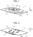
FIG. 1 is a perspective view showing a connector according toEmbodiment 1 of the present invention when viewed from an obliquely upper position. -
FIG. 2 is a perspective view showing the connector according toEmbodiment 1 when viewed from an obliquely lower position. -
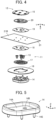
FIG. 3 is an assembly view showing the connector according toEmbodiment 1 when viewed from an obliquely upper position. -
FIG. 4 is an assembly view showing the connector according toEmbodiment 1 when viewed from an obliquely lower position. -
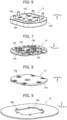
FIG. 5 is a perspective view showing a first insulator used in the connector according toEmbodiment 1 when viewed from an obliquely upper position. -
FIG. 6 is a perspective view showing the first insulator used in the connector according toEmbodiment 1 when viewed from an obliquely lower position. -
FIG. 7 is a perspective view of a second insulator used in the connector according toEmbodiment 1 when viewed from an obliquely upper position. -
FIG. 8 is a perspective view showing the second insulator used in the connector according toEmbodiment 1 when viewed from an obliquely lower position. -
FIG. 9 is a perspective view showing a reinforcement sheet used in the connector according toEmbodiment 1. -
FIG. 10 is a perspective view showing a protection sheet used in the connector according toEmbodiment 1. -
FIG. 11 is a perspective view showing a fixing sheet used in the connector according toEmbodiment 1. -
FIG. 12 is a perspective view showing a contact used in the connector according toEmbodiment 1 when viewed from an obliquely upper position. -
FIG. 13 is a perspective view showing the contact used in the connector according toEmbodiment 1 when viewed from an obliquely lower position. -
FIG. 14 is a perspective view showing a flexible substrate to which the connector according toEmbodiment 1 is to be attached when viewed from an obliquely upper position. -
FIG. 15 is a perspective view showing the flexible substrate to which the connector according toEmbodiment 1 is to be attached when viewed from an obliquely lower position. -
FIG. 16 is a partial cross-sectional perspective view showing a state where the reinforcement sheet is attached to the first insulator. -
FIG. 17 is a partial cross-sectional perspective view showing a state where an adhesive agent is applied to the first insulator. -
FIG. 18 is a partial cross-sectional perspective view showing a state where a contact is assembled to the first insulator. -
FIG. 19 is a partial perspective view showing a relationship between the adhesive agent and the contact with the first insulator being omitted. -
FIG. 20 is a partial cross-sectional perspective view showing a state where the protection sheet is assembled on the first insulator and the contact. -
FIG. 21 is a partial cross-sectional perspective view showing a state where the flexible substrate is assembled on the protection sheet. -
FIG. 22 is a partial cross-sectional perspective view showing a state where the fixing sheet is assembled on the flexible conductor. -
FIG. 23 is a partial cross-sectional perspective view showing a state where the adhesive agent is applied to the fixing sheet. -
FIG. 24 is a partial cross-sectional perspective view showing a state where the second insulator is assembled. -
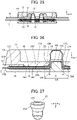
FIG. 25 is a cross-sectional view showing the state where the second insulator is assembled. -
FIG. 26 is a partial enlarged cross-sectional view showing a main part of the connector according toEmbodiment 1. -
FIG. 27 is a perspective view showing a contact used in a connector according toEmbodiment 2 when viewed from an obliquely lower position. -
FIG. 28 is an assembly view showing the connector according toEmbodiment 2 when viewed from an obliquely lower position. -
FIG. 29 is a cross-sectional view showing the connector according toEmbodiment 2 in a state where the second insulator is assembled. -
FIG. 30 is a partial enlarged cross-sectional view showing a main part of the connector according toEmbodiment 2. -
FIG. 31 is a cross-sectional view showing a connector according toEmbodiment 3. -
FIG. 32 is a partial cross-sectional view showing a conventional connector. - Embodiments of the present invention are described below with reference to the accompanying drawings.
-
FIGS. 1 and 2 show aconnector 11 according to Embodiment 1. Theconnector 11 is used as, for example, a garment-side connector portion for fitting a wearable device and is mounted on a sheet-likeflexible substrate 21. - The
connector 11 includes ahousing 12 made of an insulating material. In thehousing 12, fourcontacts 13 are retained so as to project perpendicularly to theflexible substrate 21 in two arrays parallel to each other. - The
housing 12 includes afirst insulator 14 that is disposed on afront surface 21A of theflexible substrate 21, and asecond insulator 15 that is disposed on arear surface 21B of theflexible substrate 21 and faces thefirst insulator 14. Thefirst insulator 14 and thesecond insulator 15 have oval flat shapes of the substantially same size. - The
first insulator 14 is disposed on thefront surface 21A of theflexible substrate 21 via areinforcement sheet 16 and has a recessedportion 14A opening in the opposite direction from theflexible substrate 21. In the recessedportion 14A of thefirst insulator 14, the fourcontacts 13 project perpendicularly to a bottom surface of flat shape of the recessedportion 14A. - For convenience, the bottom surface of the recessed
portion 14A of thefirst insulator 14 is defined as extending along an XY plane, the direction in which the fourcontacts 13 are aligned in two arrays is referred to as "X direction," and the direction in which the fourcontacts 13 project is referred to as "+Z direction." The Z direction is a fitting direction in which theconnector 11 is fitted to a counter connector (not shown), and the recessedportion 14A of thefirst insulator 14 constitutes a counter connector accommodating portion in which part of a counter connector (not shown) is to be accommodated. -
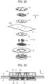
FIGS. 3 and4 show assembly views of theconnector 11. Thereinforcement sheet 16 is disposed on the -Z direction side of thefirst insulator 14, the fourcontacts 13 are disposed on the -Z direction side of thereinforcement sheet 16 via anadhesive agent 17, and theflexible substrate 21 is disposed on the -Z direction side of the fourcontacts 13 via aprotection sheet 18. Further, a fixingsheet 19 is disposed on the -Z direction side of theflexible substrate 21, and thesecond insulator 15 is disposed on the -Z direction side of the fixingsheet 19 via anadhesive agent 20. - As shown in
FIGS. 5 and6 , thefirst insulator 14 includes four contact insertion holes 14B penetrating the bottom surface of the recessedportion 14A in the Z direction. The four contact insertion holes 14B separately correspond to the fourcontacts 13. In addition, at a center portion on the -Z direction side of thefirst insulator 14, aflat surface 14C is formed to extend along an XY plane and face in the -Z direction. At a peripheral edge portion of theflat surface 14C, acircumferential surface 14D is formed so as to surround the entire periphery of theflat surface 14C, whichcircumferential surface 14D is situated on the +Z direction side of theflat surface 14C, extends along an XY plane and faces in the -Z direction. - In addition, on the
flat surface 14C and thecircumferential surface 14D of thefirst insulator 14, a plurality of fixingposts 14E are formed to project in the -Z direction. - As shown in
FIGS. 7 and 8 , thesecond insulator 15 includes abase portion 15A of flat plate shape and fourprojections 15B projecting in the +Z direction from thebase portion 15A. The fourprojections 15B separately correspond to the fourcontacts 13. At a center portion of thebase portion 15A, a flat surface 15C is formed to extend along an XY plane and face in the +Z direction, and the fourprojections 15B project in the +Z direction from the flat surface 15C. At a peripheral edge portion of the flat surface 15C, acircumferential surface 15D is formed so as to surround the entire periphery of the flat surface 15C, extend along an XY plane and face in the +Z direction. - In addition, in the flat surface 15C and the
circumferential surface 15D of thesecond insulator 15, a plurality of through-holes 15E are formed to penetrate thebase portion 15A in the Z direction. The plurality of through-holes 15E separately correspond to the plurality of fixingposts 14E of thefirst insulator 14. - The
reinforcement sheet 16 is provided to reinforce theflexible substrate 21 and has an outer peripheral portion larger than thefirst insulator 14 when viewed in the Z direction, and as shown inFIG. 9 , at a center portion of thereinforcement sheet 16, anopening portion 16A is formed to penetrate thereinforcement sheet 16. Theopening portion 16A has a size and a shape that correspond to theflat surface 14C of thefirst insulator 14. In addition, thereinforcement sheet 16 has a thickness corresponding to a height difference in the Z direction between theflat surface 14C and thecircumferential surface 14D of thefirst insulator 14. - Around the
opening portion 16A, a plurality of through-holes 16B are formed to penetrate thereinforcement sheet 16. The plurality of through-holes 16B separately correspond to the plurality of fixingposts 14E of thefirst insulator 14. - The
reinforcement sheet 16 as above is formed of, for example, a resin having excellent stretchability such as polyurethane. - As shown in
FIG. 10 , theprotection sheet 18 is constituted of an insulating film having an oval shape slightly smaller than an outline of thecircumferential surface 14D of thefirst insulator 14 and larger than the openingportion 16A of thereinforcement sheet 16, and at a center portion of theprotection sheet 18, fourprojection insertion holes 18A are formed to penetrate theprotection sheet 18. These fourprojection insertion holes 18A separately correspond to the fourcontacts 13. - As an insulating film constituting the
protection sheet 18, for example, a polyethylene terephthalate (PET) film (heat resistant temperature: about 150°C), a polyimide film (heat resistant temperature: about 200°C), a so-called retort pouch (heat resistant temperature: about 130°C) produced by performing laminate processing with a resin film such as polypropylene can be used. - Three through-
holes 18B penetrating theprotection sheet 18 are formed on a center line in the Y direction of theprotection sheet 18, and fourcutouts 18C are formed at a +Y directional edge portion and a -Y directional edge portion of theprotection sheet 18. These through-holes 18B andcutouts 18C separately correspond to the plurality of fixingposts 14E of thefirst insulator 14. - A pressure-sensitive adhesive layer is formed over an entire area of a surface, of opposite surfaces of the
protection sheet 18, facing in the -Z direction, i.e., facing thefront surface 21A of theflexible substrate 21. A pressure-sensitive adhesive layer exhibits an adhesion effect only by being pressurized for a short time at normal temperature without using water, a solvent, heat or the like. A pressure-sensitive adhesive layer is not formed on a surface, facing in the +Z direction, of theprotection sheet 18. - As shown in
FIG. 11 , the fixingsheet 19 has the same size, shape and material as those of theprotection sheet 18. In other words, the fixingsheet 19 is constituted of an insulating film having an oval shape slightly smaller than the outline of thecircumferential surface 14D of thefirst insulator 14, and at a center portion of the fixingsheet 19, fourprojection insertion holes 19A are formed to penetrate the fixingsheet 19. These fourprojection insertion holes 19A separately correspond to the fourcontacts 13. - Three through-
holes 19B penetrating the fixingsheet 19 are formed on a center line in the Y direction of the fixingsheet 19, and fourcutouts 19C are formed at a +Y directional edge portion and a -Y directional edge portion of the fixingsheet 19. These through-holes 19B andcutouts 19C separately correspond to the plurality of fixingposts 14E of thefirst insulator 14. - A pressure-sensitive adhesive layer is formed over an entire area of a surface, of opposite surfaces of the fixing
sheet 19, facing in the +Z direction, i.e., facing therear surface 21B of theflexible substrate 21. A pressure-sensitive adhesive layer is not formed on a surface, facing in the -Z direction, of the fixingsheet 19. - As shown in
FIGS. 12 and13 , thecontact 13 is a plug-type contact made of a conductive material such as metal and includes atubular portion 13A of cylindrical shape that extends in the +Z direction and aflange 13B that is formed integrally with the -Z directional end of thetubular portion 13A and extends out of thetubular portion 13A along an XY plane. - The
tubular portion 13A of thecontact 13 has an outside diameter smaller than an inside diameter of thecontact insertion hole 14B of thefirst insulator 14, and theflange 13B of thecontact 13 has an outside diameter larger than the inside diameter of thecontact insertion hole 14B of thefirst insulator 14. - The
tubular portion 13A is provided in its interior with aprojection accommodating portion 13C of recess shape opening in the -Z direction. The projectionaccommodating portion 13C has an inside diameter slightly smaller than a value obtained by adding a double of a thickness of theflexible substrate 21 to an outside diameter of theprojection 15B of thesecond insulator 15. Thecontact 13 as above can be manufactured by, for example, performing press working, cutting, drawing or other processing on a metal material. - As shown in
FIGS. 14 and 15 , theflexible substrate 21 is configured such that a plurality offlexible conductors 23 are formed, by printing, on a front surface of asubstrate body 22 constituted of a resin film. Theflexible substrate 21 is disposed on cloth of a garment and heated with an iron or the like, and a resin film forming thesubstrate body 22 is melted so that theflexible substrate 21 is welded to the cloth of the garment, whereby wiring constituted of theflexible conductors 23 can be formed on the front surface of the garment. - Note that the
connector 11 can also be attached to a surface of a garment in which wiring constituted of theflexible conductor 23 is formed in advance. - On the
front surface 21A of theflexible substrate 21, twoflexible conductors 23 are disposed to extend in parallel to each other in the +X direction from a center portion of theflexible substrate 21, and twoflexible conductors 23 are disposed to extend in parallel to each other in the -X direction from the center portion of theflexible substrate 21. Theseflexible conductors 23 separately correspond to the fourcontacts 13. Aflexible conductor 23 is not disposed on therear surface 21B of theflexible substrate 21. - At a center portion of the
substrate body 22 of theflexible conductor 21, a plurality of through-holes 22A are formed to penetrate thesubstrate body 22. These through-holes 22A are separately correspond to the plurality of fixingposts 14E of thefirst insulator 14. - The
adhesive agent 17 shown inFIGS. 3 and4 allows a surface, facing in the +Z direction, of theprotection sheet 18 to be adhered to theflat surface 14C of thefirst insulator 14 and to an edge portion of theopening portion 16A of thereinforcement sheet 16, the edge portion surrounding theopening portion 16A, and fills between thetubular portion 13A of thecontact 13 and thecontact insertion hole 14B of thefirst insulator 14 over a whole circumference of thetubular portion 13A. - In addition, the
adhesive agent 20 allows a surface, facing in the -Z direction, of the fixingsheet 19 to be adhered to the flat surface 15C and thecircumferential surface 15D of thesecond insulator 15. - As these
adhesive agents - Note that an insulating film and a pressure-sensitive adhesive layer constituting each of the
protection sheet 18 and the fixingsheet 19 each have a heat resistant temperature higher than a heating treatment temperature of theadhesive agents adhesive agents protection sheet 18 and the fixingsheet 19 are not dissolved, and an adhesion effect by the pressure-sensitive adhesive layer is not substantially impaired. - Here, a method of attaching the
connector 11 to theflexible substrate 21 is described. - First, as shown in
FIG. 16 , thereinforcement sheet 16 is moved toward thefirst insulator 14 from the -Z direction to the +Z direction while the plurality of fixingposts 14E of thefirst insulator 14 are separately passed through the plurality of through-holes 16B of thereinforcement sheet 16, whereby thereinforcement sheet 16 is attached to thefirst insulator 14. Thus, theflat surface 14C of thefirst insulator 14 is inserted into theopening portion 16A of thereinforcement sheet 16, and the edge portion of theopening portion 16A of thereinforcement sheet 16 makes contact with thecircumferential surface 14D of thefirst insulator 14. - In addition, since the
reinforcement sheet 16 has the thickness corresponding to the height difference in the Z direction between theflat surface 14C and thecircumferential surface 14D of thefirst insulator 14, thereinforcement sheet 16 attached to thefirst insulator 14 forms the same plane as theflat surface 14C of thefirst insulator 14. - Next, as shown in
FIG. 17 , theadhesive agent 17 is applied on theflat surface 14C, facing in the -Z direction, of thefirst insulator 14 and on the edge portion of theopening portion 16A of thereinforcement sheet 16. At this time, theadhesive agent 17 is applied also on an edge portion of each of the four contact insertion holes 14B opening in theflat surface 14C of thefirst insulator 14. - Further, as shown in
FIG. 18 , the correspondingcontact 13 is assembled to each of the four contact insertion holes 14B of thefirst insulator 14. Thetubular portion 13A of each of thecontacts 13 is inserted into the correspondingcontact insertion hole 14B. - At this time, with the
first insulator 14 being omitted and when viewed from the +Z direction, as shown inFIG. 19 , theadhesive agent 17 applied on theflat surface 14C of thefirst insulator 14 is situated on theflange 13B of each of thecontacts 13. - Next, as shown in
FIG. 20 , theprotection sheet 18 is attached to thefirst insulator 14 on which theadhesive agent 17 is applied and to which the fourcontacts 13 are assembled. Theprotection sheet 18 is attached by having the plurality of fixingposts 14E of thefirst insulator 14 to separately pass through the plurality of through-holes 18B and thecutouts 18C of theprotection sheet 18. At this time, theprotection sheet 18 is disposed such that its surface on which the pressure-sensitive adhesive layer is formed faces in the -Z direction opposite to thefirst insulator 14, and each of theprojection insertion holes 18A of theprotection sheet 18 is disposed on the -Z direction side of thecorresponding contact 13. - Further, as shown in
FIG. 21 , theflexible substrate 21 is moved from the -Z direction to the +Z direction while the plurality of fixingposts 14E of thefirst insulator 14 are separately passed through the plurality of through-holes 22A of theflexible substrate 21, whereby theflexible substrate 21 is assembled to theprotection sheet 18 on the -Z direction side of theprotection sheet 18. At this time, theflexible substrate 21 is disposed such that thefront surface 21A on which theflexible conductors 23 are formed faces theprotection sheet 18. - Thereafter, as shown in
FIG. 22 , the fixingsheet 19 is attached to therear surface 21B of theflexible substrate 21 while the plurality of fixingposts 14E of thefirst insulator 14 are separately passed through the plurality of through-holes 19B of the fixingsheet 19. At this time, the fixingsheet 19 is disposed such that its surface on which the pressure-sensitive adhesive layer is formed faces therear surface 21B of theflexible substrate 21, and each of theprojection insertion holes 19A of the fixingsheet 19 is disposed on the -Z direction side of thecorresponding contact 13 with theflexible substrate 21 being sandwiched therebetween. - Next, as shown in
FIG. 23 , theadhesive agent 20 is applied on the surface, facing in the -Z direction, of the fixingsheet 19, and thereafter, as shown inFIG. 24 , thesecond insulator 15 is assembled to thefirst insulator 14 while the plurality of fixingposts 14E of thefirst insulator 14 are separately passed through the plurality of through-holes 15E of thesecond insulator 15. At this time, the flat surface 15C and thecircumferential surface 15D of thesecond insulator 15 are disposed on theadhesive agent 20 applied on the surface of the fixingsheet 19, and a +Z directional end portion of theprojection 15B is disposed in theprojection insertion hole 19A of the fixingsheet 19. - Thus, as shown in
FIG. 25 , thesecond insulator 15, theadhesive agent 20, the fixingsheet 19, theflexible substrate 21, theprotection sheet 18, the fourcontacts 13, theadhesive agent 17, thereinforcement sheet 16, and thefirst insulator 14 are sequentially stacked from the -Z direction to the +Z direction. - In this state, while the
second insulator 15 is relatively pressurized toward thefirst insulator 14, a heating treatment is performed in order to cure theadhesive agents - When the
second insulator 15 is relatively pressurized toward thefirst insulator 14, theadhesive agent 17 applied on theflat surface 14C of thefirst insulator 14 and the edge portion of theopening portion 16A of thereinforcement sheet 16 extends and spreads on an XY plane between theflat surface 14C of thefirst insulator 14 and theprotection sheet 18, and thereinforcement sheet 16 and theprotection sheet 18, and theadhesive agent 17 applied on the edge portions of the contact insertion holes 14B of thefirst insulator 14 fills between the contact insertion holes 14B and thetubular portions 13A of thecontacts 13. Similarly, theadhesive agent 20 applied on the surface of the fixingsheet 19 extends and spreads on an XY plane between the fixingsheet 19 and thesecond insulator 15. - In addition, when a heating treatment is performed, the
adhesive agents - Thereafter, -Z directional ends, which project in the -Z direction from the plurality of through-
holes 15E of thesecond insulator 15, of the plurality of fixingposts 14E of thefirst insulator 14 are heated and deformed, whereby thesecond insulator 15 is fixed to thefirst insulator 14, and the fourcontacts 13 are retained in thehousing 12 constituted of thefirst insulator 14 and thesecond insulator 15. - Attachment of the
connector 11 to theflexible substrate 21 is thus completed. -
FIG. 26 shows a main part of theconnector 11 attached to theflexible substrate 21 in this manner. Theadhesive agents adhesive agent layer 20A, respectively. - The first
adhesive agent layer 17A allows the surface, facing in the +Z direction, of theprotection sheet 18 to be adhered to theflat surface 14C of thefirst insulator 14 and the edge portion of theopening portion 16A of thereinforcement sheet 16, the edge portion surrounding theopening portion 16A, and further, the firstadhesive agent layer 17A fills between thetubular portion 13A and thecontact insertion hole 14B of thefirst insulator 14 over the whole circumference of thetubular portion 13A of thecontact 13. In addition, the secondadhesive agent layer 20A allows the surface, facing in the -Z direction, of the fixingsheet 19 to be adhered to the flat surface 15C and thecircumferential surface 15D of thesecond insulator 15. - In addition, the
second insulator 15 is relatively pressurized toward thefirst insulator 14, whereby theprojection 15B of thesecond insulator 15 makes contact with therear surface 21B of theflexible substrate 21 in theprojection insertion hole 19A of the fixingsheet 19 and is accommodated in theprojection accommodating portion 13C of thecontact 13 with theflexible substrate 21 being sandwiched therebetween, while pushing theflexible substrate 21 in the +Z direction through theprojection insertion holes 18A of theprotection sheet 18. Since theprojection accommodating portion 13C has the inside diameter slightly smaller than a value obtained by adding a double of the thickness of theflexible substrate 21 to the outside diameter of theprojection 15B, theflexible conductors 23 of theflexible substrate 21 are pressed by a lateral surface of theprojection 15B against the inner surface of theprojection accommodating portion 13C of thecontact 13 such that a contact pressure is applied thereto, whereby thecontact 13 is electrically connected to theflexible conductors 23. - In an XY plane along the
protection sheet 18, theprojection insertion hole 18A of theprotection sheet 18 has an inside diameter D1 smaller than a size of a part of thecontact 13, which part makes contact with theprotection sheet 18, i.e., an outside diameter D2 of theflange 13B of thecontact 13. In addition, theflange 13B of thecontact 13 is situated on the +Z direction side of theprotection sheet 18, and the firstadhesive agent layer 17A is situated on the +Z direction side of theflange 13B of thecontact 13. Further, the firstadhesive agent layer 17A is disposed on the inner side of an outer peripheral portion of theprotection sheet 18. Therefore, the firstadhesive agent layer 17A does not make contact with thefront surface 21A of theflexible conductor 21. - Similarly, the second
adhesive agent layer 20A is disposed on the inner side of an outer peripheral portion of the fixingsheet 19 so that the secondadhesive agent layer 20A does not make contact with therear surface 21B of theflexible substrate 21. - In addition, an insulating film and a pressure-sensitive adhesive layer constituting each of the
protection sheet 18 and the fixingsheet 19 each have a heat resistant temperature higher than a predetermined heating treatment temperature of adhesive agents separately constituting theadhesives - Therefore, when the
adhesive agents adhesive agents adhesive agents flexible conductors 23 formed on theflexible substrate 21, particularly, thefront surface 21A of theflexible substrate 21. Consequently, deformation and disconnection of theflexible conductors 23 caused by the flowingadhesive agents - In addition, since the
adhesive agents flexible conductors 23, a constituent material of each of theadhesive agents - In addition, since the
protection sheet 18 is adhered to thefront surface 21A of theflexible substrate 21 with the pressure-sensitive adhesive layer and to thefirst insulator 14 and thereinforcement sheet 16 with the firstadhesive agent layer 17A, and the fixingsheet 19 is adhered to therear surface 21B of theflexible substrate 21 with the pressure-sensitive adhesive layer and to thesecond insulator 15 with the secondadhesive agent layer 20A, water can be prevented from penetrating from the outside to the inside of theconnector 11 through thefront surface 21A and therear surface 21B of theflexible substrate 21. - Further, since the first
adhesive agent layer 17A fills between thetubular portion 13A and thecontact insertion hole 14B of thefirst insulator 14 over the whole circumference of thetubular portion 13A of thecontact 13, even when a waterproof member such as an O-ring is not used, water can be prevented from penetrating to the inside of theconnector 11 through thecontact insertion hole 14B of thefirst insulator 14. - While the first
adhesive agent layer 17A and the secondadhesive agent layer 20A are disposed on the inner side of theprotection sheet 18 and on the inner side of the fixingsheet 19, respectively, in order to prevent water from penetrating from the outside to the inside of theconnector 11 through thefront surface 21A and therear surface 21B of theflexible substrate 21, the firstadhesive agent layer 17A and the secondadhesive agent layer 20A are preferably disposed in a region equal to or larger than a predetermined area while surrounding the periphery of each of the fourcontacts 13. - In addition, since the
flexible conductors 23 are formed only on thefront surface 21A of theflexible substrate 21 and not exposed on therear surface 21B of theflexible substrate 21, the fixingsheet 19 adhered to therear surface 21B of theflexible substrate 21 may be omitted. As long as theprotection sheet 18 is adhered to thefront surface 21A of theflexible conductor 21, deformation and disconnection of theflexible conductors 23 caused by the flowingadhesive agent 17 can be prevented. - However, since the presence of the fixing
sheet 19 can prevent thesubstrate body 22 of theflexible substrate 21 from directly receiving a force from the flowingadhesive agent 20, the fixingsheet 19 is preferably disposed between therear surface 21B of theflexible substrate 21 and theadhesive agent 20 applied to thesecond insulator 15. - While the
connector 11 according toEmbodiment 1 above includes the fourcontacts 13, the invention is not limited thereto, and it suffices if at least onecontact 13 is provided. - In
Embodiment 1 above, as shown inFIGS. 12 and13 , thecontact 13 includes theflange 13B that is formed integrally with the -Z directional end of thetubular portion 13A and extends out of thetubular portion 13A along an XY plane, but a contact having no flange may be used. -
FIG. 27 shows acontact 33 used inEmbodiment 2. Thecontact 33 is made of a conductive material such as metal and includes atubular portion 33A of cylindrical shape that extends in the +Z direction, and thetubular portion 33A is provided in its interior with aprojection accommodating portion 33C of recess shape opening in the -Z direction. The projectionaccommodating portion 33C has an inside diameter slightly smaller than a value obtained by adding a double of the thickness of theflexible substrate 21 to the outside diameter of theprojection 15B of thesecond insulator 15. A flange extending out of thetubular portion 33A is not formed at a -Z directional end of thetubular portion 33A. -
FIG. 28 is an assembly view of aconnector 31 according toEmbodiment 2 having thecontact 33 described above. Thereinforcement sheet 16 is disposed on the -Z direction side of afirst insulator 34, the fourcontacts 33 are disposed on the -Z direction side of thereinforcement sheet 16 via theadhesive agent 17, and theflexible substrate 21 is disposed on the -Z direction side of the fourcontacts 33 via theprotection sheet 18. Further, the fixingsheet 19 is disposed on the -Z direction side of theflexible substrate 21, and thesecond insulator 15 is disposed on the -Z direction side of the fixingsheet 19 via theadhesive agent 20. - In other words, in the
connector 31 according toEmbodiment 2, the fourcontacts 33 and thefirst insulator 34 are used instead of the fourcontacts 13 and thefirst insulator 14, respectively, in theconnector 11 ofEmbodiment 1, and theconnector 31 otherwise has the same configuration as theconnector 11 ofEmbodiment 1. - A method in which the
connector 31 is attached to theflexible substrate 21 is the same as the method in which theconnector 11 ofEmbodiment 1 is attached to theflexible substrate 21, and as shown inFIG. 29 , thesecond insulator 15, theadhesive agent 20, the fixingsheet 19, theflexible substrate 21, theprotection sheet 18, the fourcontacts 33, theadhesive agent 17, thereinforcement sheet 16, and thefirst insulator 34 are sequentially stacked from the -Z direction to the +Z direction. In this state, while thesecond insulator 15 is relatively pressurized toward thefirst insulator 34, a heating treatment is performed in order to cure theadhesive agents connector 31 to theflexible substrate 21 is thus completed. -
FIG. 30 shows a main part of theconnector 31 attached to theflexible substrate 21. Thefirst insulator 34 includes contact insertion holes 34B instead of the contact insertion holes 14B in thefirst insulator 14 inEmbodiment 1, and otherwise has the same configuration as thefirst insulator 14 inEmbodiment 1. Thecontact insertion hole 34B has a shape corresponding to the outer shape of thetubular portion 33A of thecontact 33. - In an XY plane along the
protection sheet 18, theprojection insertion hole 18A of theprotection sheet 18A has an inside diameter D1 smaller than a size of a part of thecontact 33, which part makes contact with theprotection sheet 18, i.e., an outside diameter D3 of thetubular portion 33A. In addition, a -Z direction end of thetubular portion 33A of thecontact 33 is situated on the +Z direction side of theprotection sheet 18, and the firstadhesive agent layer 17A fills between thetubular portion 33A and thecontact insertion hole 34B of thefirst insulator 34 over a whole circumference of the -Z direction end of thetubular portion 33A. Further, the firstadhesive agent layer 17A is disposed on the inner side of an outer peripheral portion of theprotection sheet 18. Therefore, the firstadhesive agent layer 17A does not make contact with thefront surface 21A of theflexible conductor 21. - Therefore, also in the
connector 31 ofEmbodiment 2, when theadhesive agents adhesive agents flexible substrate 21, particularly, theflexible conductors 23 formed on thefront surface 21A of theflexible substrate 21. Consequently, deformation and disconnection of theflexible conductors 23 caused by the flowingadhesive agents - Further, the
second insulator 15 is relatively pressurized toward thefirst insulator 34 so that theprojection 15B of thesecond insulator 15 is accommodated in theprojection accommodating portion 33C of thecontact 33 with theflexible substrate 21 being sandwiched therebetween, while pushing theflexible substrate 21 in the +Z direction. Since theprojection accommodating portion 33C has the inside diameter slightly smaller than a value obtained by adding a double of the thickness of theflexible substrate 21 to the outside diameter of theprojection 15B, theflexible conductors 23 of theflexible substrate 21 are pressed by the lateral surface of theprojection 15B against the inner surface of theprojection accommodating portion 33C of thecontact 33 such that a contact pressure is applied thereto, whereby thecontact 33 is electrically connected to theflexible conductors 23. - Also in the
connector 31 ofEmbodiment 2, theprotection sheet 18 is adhered to thefront surface 21A of theflexible substrate 21 with the pressure-sensitive adhesive layer and to thefirst insulator 34 and thereinforcement sheet 16 with the firstadhesive agent layer 17A, and the fixingsheet 19 is adhered to therear surface 21B of theflexible substrate 21 with the pressure-sensitive adhesive layer and to thesecond insulator 15 with the secondadhesive agent layer 20A, whereby water can be prevented from penetrating from the outside to the inside of theconnector 11 through thefront surface 21A and therear surface 21B of theflexible substrate 21. - Further, since the first
adhesive agent layer 17A fills between thetubular portion 33A and thecontact insertion hole 34B of thefirst insulator 34 over the whole circumference of the -Z direction end of thetubular portion 33A of thecontact 33, even when a waterproof member such as an O-ring is not used, water can be prevented from penetrating to the inside of theconnector 31 through the contact insertion holes 34B of thefirst insulator 34. - In
Embodiments projection 15B of thesecond insulator 15 is accommodated in theprojection accommodating portion contact flexible substrate 21 being sandwiched therebetween, whereby thecontact flexible conductor 23, but the invention is not limited thereto. -
FIG. 31 shows aconnector 41 according toEmbodiment 3. Theconnector 41 includes a housing constituted of afirst insulator 44 and asecond insulator 45, a recessedportion 44A is formed in thefirst insulator 44, and the protrudingportion 45A is formed in thesecond insulator 45. - The
contact 43 constituted of a band-like member made of a conductive material such as metal is temporarily held in the recessedportion 44A of thefirst insulator 44. In this state, thesecond insulator 45 is assembled to thefirst insulator 44 with aflexible substrate 51 being sandwiched therebetween, whereby theconnector 41 is attached to theflexible substrate 51. - The
flexible substrate 51 is configured such that theflexible conductor 53 is formed, by printing, on a front surface of asubstrate body 52 constituted of a resin film, aprotection sheet 48 is disposed on a front surface, on which theflexible conductor 53 is exposed, of theflexible substrate 51, and a fixingsheet 49 is disposed on a rear surface, on which theflexible conductor 53 is not exposed, of theflexible substrate 51. Theprotection sheet 48 and the fixingsheet 49 are each obtained by forming a pressure-sensitive adhesive layer on one surface of an insulating film and are respectively adhered to the front surface and the rear surface of theflexible substrate 51 with the pressure-sensitive adhesive layers. - On a front surface of part of the
flexible substrate 51, which part is situated in the recessedportion 44A of thefirst insulator 44, theprotection sheet 48 is not disposed but theflexible conductor 53 is exposed, and the exposedflexible conductor 53 makes contact with thecontact 43, with predetermined contact pressure, temporarily held in the recessedportion 44A of thefirst insulator 44 by the protrudingportion 45A of thesecond insulator 45, whereby thecontact 43 is electrically connected to theflexible conductor 53. - In addition, the
protection sheet 48 is adhered to thefirst insulator 44 and thereinforcement sheet 46 with a firstadhesive agent layer 47A (adhesive layer), and the fixingsheet 49 is adhered to thesecond insulator 45 with a secondadhesive agent layer 50A, whereby water is prevented from penetrating to a connection part between thecontact 43 and theflexible conductor 53. - Here, the
protection sheet 48 is present between theflexible substrate 51 and the first adhesive agent layer 47, the fixingsheet 49 is present between theflexible substrate 51 and the secondadhesive agent layer 50A, and the firstadhesive agent layer 47A and the secondadhesive agent layer 50A do not make direct contact with theflexible substrate 51. An insulating film and a pressure-sensitive adhesive layer constituting each of theprotection sheet 48 and the fixingsheet 49 each have a heat resistant temperature higher than a predetermined heating treatment temperature of adhesive agents separately constituting the firstadhesive agent layer 47A and the secondadhesive agent layer 50A. - Thus, when the adhesive agents separately constituting the first
adhesive agent layer 47A and the secondadhesive agent layer 50A are heated to the predetermined heating treatment temperature, the flowing adhesive agents can be prevented from making contact with and applying a force to theflexible substrate 51, and consequently, deformation and disconnection of theflexible conductor 53 caused by the flowing adhesive agents can be prevented. - With this configuration, also in the
connector 41 in which thecontact 43 is electrically connected to theflexible conductor 53, thesecond insulator 45 is assembled to thefirst insulator 44 with theflexible substrate 51 being sandwiched therebetween, whereby disconnection of theflexible conductor 53 when the adhesive agents are heated to provide waterproof property can be prevented, and highly reliable electrical connection can be established. - In
Embodiments 1 to 3, as theadhesive agent 17 constituting the firstadhesive agent layer 17A, theadhesive agent 20 constituting the secondadhesive agent layer 20A, and the adhesive agents separately constituting the firstadhesive agent layer 47A and the secondadhesive agent layer 50A, an adhesive agent made of a thermosetting resin is used, but it suffices if an adhesive agent which is cured by a heating treatment is used, and an adhesive agent made of a thermoplastic resin may also be used. For example, an adhesive agent made of a thermoplastic resin takes on a solid at room temperature, is softened when heated, and then cured when cooled. Such an adhesive agent made of a thermoplastic resin is disposed on the corresponding adhesive position and subjected to a heating treatment. The adhesive agent thus softened to be flowing is pressurized and fills the adhesive position, and then is cooled and cured to form the firstadhesive agent layer adhesive agent layer - In addition, while, in
Embodiments 1 to 3, theconnector flexible substrate reinforcement sheet reinforcement sheet flexible substrate
Claims (18)
- A connector (11, 31, 41) attached to a flexible substrate (21, 51) having a sheet-like shape and having a flexible conductor (23, 53) formed on a front surface of a substrate body (22, 52), the connector comprising:at least one contact (13, 33, 43) made of a conductive material and connected to the flexible conductor,a housing (12) that is attached to the flexible substrate and retains the contact; anda protection sheet (18, 48) constituted of an insulating film having a pressure-sensitive adhesive layer formed on one surface of the protection sheet and disposed between the housing and the flexible substrate such that the pressure-sensitive adhesive layer faces the flexible substrate,wherein the protection sheet is disposed so as to cover at least a front surface part of the flexible substrate on which the flexible conductor is formed, and is adhered to the flexible substrate with the pressure-sensitive adhesive layer,wherein the housing has a flat surface (14C, 15C) facing the flexible substrate, andwherein an adhesive layer (17A, 47A) bonding the housing to the protection sheet is disposed between the flat surface and the protection sheet.
- The connector according to claim 1,wherein the housing (12) includes: a first insulator (14, 34, 44) that is disposed on one surface of the flexible substrate and retains the contact; and the second insulator (15, 45) that is disposed on another surface of the flexible substrate, andwherein each of the first insulator and the second insulator has the flat surface.
- The connector according to claim 2,wherein the flexible conductor is formed on the one surface of the flexible substrate,wherein the protection sheet is disposed between the first insulator and the one surface of the flexible substrate,wherein the protection sheet is adhered to the one surface of the flexible substrate with the pressure-sensitive adhesive layer, andwherein a first adhesive agent layer (17A, 47A) which becomes the adhesive layer is disposed between the flat surface of the first insulator and the protection sheet.
- The connector according to claim 3, further including a fixing sheet (19) constituted of the insulating film and disposed between the second insulator and the another surface of the flexible substrate such that the pressure-sensitive adhesive layer faces the another surface of the flexible substrate,wherein the fixing sheet is adhered to the another surface of the flexible substrate with the pressure-sensitive adhesive layer, andwherein a second adhesive agent layer (20A) bonding the second insulator to the fixing sheet is disposed between the flat surface of the second insulator and the fixing sheet.
- The connector according to claim 3, wherein a second adhesive agent layer (50A) bonding the second insulator to the flexible substrate is disposed between the flat surface of the second insulator and the another surface of the flexible substrate.
- The connector according to any one of claims 3-5,wherein the contact (13, 33) includes a projection accommodating portion (13C, 33C) of recess shape,wherein the second insulator has a projection (15B) projecting toward the another surface of the flexible substrate, andwherein the projection is accommodated in the projection accommodating portion with the flexible conductor being sandwiched therebetween, whereby the contact is electrically connected to the flexible conductor.
- The connector according to claim 6,wherein the protection sheet (18) includes a projection insertion hole (18A) disposed at a position corresponding to the projection accommodating portion of the contact, andwherein the projection is accommodated in the projection accommodating portion together with the flexible substrate via the projection insertion hole.
- The connector according to claim 7, wherein in a plane along the protection sheet (18), the projection insertion hole (18A) has a size smaller than that of part of the contact, the part making contact with the protection sheet.
- The connector according to claim 7 or 8,wherein the contact (13, 33) has a tubular portion (13A, 33A) extending in a direction perpendicular to the flexible substrate,wherein the projection accommodating portion (13C, 33C) is disposed inside the tubular portion, andwherein the contact is disposed such that the projection accommodating portion is disposed to be aligned with the projection insertion hole (18A).
- The connector according to claim 9,wherein the contact (13) includes a flange (13B) extending from one end of the tubular portion in a direction parallel to the flexible substrate, andwherein the contact is disposed such that a whole circumference of the flange overlaps and makes contact with the protection sheet (18).
- The connector according to claim 9 or 10,wherein the first insulator (14, 34) includes a contact insertion hole (14B, 34B) penetrating the first insulator, andwherein the contact (13, 33) is retained in the first insulator with the tubular portion being inserted into the contact insertion hole.
- The connector according to claim 11, wherein the first adhesive agent layer (17A) fills between the tubular portion (13A, 33A) of the contact (13, 33) and the contact insertion hole over a whole circumference of the tubular portion.
- The connector according to any one of claims 3-5, wherein the second insulator (15, 45) is assembled to the first insulator (14, 34, 44) with the flexible substrate being sandwiched therebetween, whereby the contact (13, 33, 43) is electrically connected to the flexible conductor (23, 53).
- The connector according to any one of claims 3-13, further including a reinforcement sheet (16, 46) disposed between the first insulator (14, 34, 44) and the one surface of the flexible substrate,wherein the reinforcement sheet includes an opening portion (16A) situated on an inner side of an outer peripheral portion of the protection sheet (18, 48), andwherein the protection sheet is adhered to the flat surface of the first insulator via the opening portion and to an edge portion of the opening portion with the first adhesive agent layer.
- The connector according to any one of claims 3-14, wherein the first adhesive agent layer (17A, 47A) is disposed on an inner side of an outer peripheral portion of the protection sheet (18, 48).
- The connector according to claim 15, wherein the first adhesive agent layer is disposed in a region equal to or larger than a predetermined area.
- The connector according to any one of claims 1-16,wherein the adhesive layer (17A, 47A) is made of an adhesive agent (17, 20) that is cured by a heating treatment, andwherein each of the insulating film and the pressure-sensitive adhesive layer has a heat resistant temperature higher than a heating treatment temperature of the adhesive agent.
- The connector according to claim 17, wherein the adhesive agent (17, 20) is made of a thermosetting resin or a thermoplastic resin.
Applications Claiming Priority (1)
| Application Number | Priority Date | Filing Date | Title |
|---|---|---|---|
| JP2021140068A JP7638829B2 (en) | 2021-08-30 | 2021-08-30 | connector |
Publications (2)
| Publication Number | Publication Date |
|---|---|
| EP4142064A1 true EP4142064A1 (en) | 2023-03-01 |
| EP4142064B1 EP4142064B1 (en) | 2023-09-06 |
Family
ID=82019849
Family Applications (1)
| Application Number | Title | Priority Date | Filing Date |
|---|---|---|---|
| EP22178353.3A Active EP4142064B1 (en) | 2021-08-30 | 2022-06-10 | Assembly comprising a flexible substrate and a connector attached to the flexible substrate |
Country Status (4)
| Country | Link |
|---|---|
| US (1) | US12237597B2 (en) |
| EP (1) | EP4142064B1 (en) |
| JP (1) | JP7638829B2 (en) |
| CN (1) | CN115732953B (en) |
Families Citing this family (1)
| Publication number | Priority date | Publication date | Assignee | Title |
|---|---|---|---|---|
| GB2614729B (en) * | 2022-01-14 | 2025-01-15 | Siemens Energy Global Gmbh & Co Kg | Connector arrangement |
Citations (2)
| Publication number | Priority date | Publication date | Assignee | Title |
|---|---|---|---|---|
| EP3598581A1 (en) * | 2018-07-18 | 2020-01-22 | Japan Aviation Electronics Industry, Limited | Garment connector |
| EP3800740A1 (en) * | 2019-10-01 | 2021-04-07 | Japan Aviation Electronics Industry, Ltd. | Connector |
Family Cites Families (16)
| Publication number | Priority date | Publication date | Assignee | Title |
|---|---|---|---|---|
| US6957963B2 (en) * | 2000-01-20 | 2005-10-25 | Gryphics, Inc. | Compliant interconnect assembly |
| US6312266B1 (en) * | 2000-08-24 | 2001-11-06 | High Connection Density, Inc. | Carrier for land grid array connectors |
| TWI244659B (en) * | 2002-03-20 | 2005-12-01 | J S T Mfg Co Ltd | Conduction layer with excellent flexibility and anisotropic conduction board using the same |
| WO2007084552A2 (en) * | 2006-01-17 | 2007-07-26 | Lifesync Corporation | Multi-lead keyhold connector |
| JP2009188488A (en) * | 2008-02-04 | 2009-08-20 | Panasonic Corp | Mobile terminal device |
| US10398376B2 (en) * | 2014-06-17 | 2019-09-03 | MAD Apparel, Inc. | Garment integrated electrical interface system and method of manufacture |
| KR102293575B1 (en) * | 2014-09-04 | 2021-08-26 | 삼성메디슨 주식회사 | Probe for ultrasonic imaging apparatus and manufacturing method thereof |
| EP3086576B1 (en) * | 2015-04-22 | 2021-09-01 | Starkey Laboratories, Inc. | Solderless module connector for a hearing assistance device assembly |
| US10096930B2 (en) * | 2016-02-24 | 2018-10-09 | Hosiden Corporation | Connector |
| CN105789986B (en) * | 2016-03-28 | 2019-02-26 | 中航光电科技股份有限公司 | Adapter connector and its contact assembly |
| JP6840559B2 (en) * | 2017-02-10 | 2021-03-10 | 日本航空電子工業株式会社 | connector |
| JP7128686B2 (en) * | 2018-08-07 | 2022-08-31 | 日本航空電子工業株式会社 | connector |
| CN111355108B (en) * | 2018-12-21 | 2023-02-24 | 豪利士电线装配(深圳)有限公司 | Sealing electric plug |
| JP7313991B2 (en) * | 2019-09-09 | 2023-07-25 | 日本航空電子工業株式会社 | connector |
| JP7348060B2 (en) * | 2019-10-03 | 2023-09-20 | 日本航空電子工業株式会社 | Connector and connection method |
| JP7348024B2 (en) * | 2019-10-24 | 2023-09-20 | 日本航空電子工業株式会社 | Connector and connection method |
-
2021
- 2021-08-30 JP JP2021140068A patent/JP7638829B2/en active Active
-
2022
- 2022-06-10 EP EP22178353.3A patent/EP4142064B1/en active Active
- 2022-06-16 US US17/842,518 patent/US12237597B2/en active Active
- 2022-06-30 CN CN202210755863.4A patent/CN115732953B/en active Active
Patent Citations (3)
| Publication number | Priority date | Publication date | Assignee | Title |
|---|---|---|---|---|
| EP3598581A1 (en) * | 2018-07-18 | 2020-01-22 | Japan Aviation Electronics Industry, Limited | Garment connector |
| EP3800740A1 (en) * | 2019-10-01 | 2021-04-07 | Japan Aviation Electronics Industry, Ltd. | Connector |
| JP2021057294A (en) | 2019-10-01 | 2021-04-08 | 日本航空電子工業株式会社 | connector |
Also Published As
| Publication number | Publication date |
|---|---|
| CN115732953B (en) | 2026-03-17 |
| US12237597B2 (en) | 2025-02-25 |
| JP2023034018A (en) | 2023-03-13 |
| CN115732953A (en) | 2023-03-03 |
| JP7638829B2 (en) | 2025-03-04 |
| EP4142064B1 (en) | 2023-09-06 |
| US20230061252A1 (en) | 2023-03-02 |
Similar Documents
| Publication | Publication Date | Title |
|---|---|---|
| CN110739565B (en) | Connector for clothes | |
| US9345134B2 (en) | Printed wiring board | |
| US10923855B2 (en) | Connector to prevent misconnection of contacts without the use of a projection and a groove | |
| CN112787153B (en) | Connector Assemblies and Connector Pairs | |
| EP4142064B1 (en) | Assembly comprising a flexible substrate and a connector attached to the flexible substrate | |
| KR20190098218A (en) | A method of contacting a contact surface on a flexible circuit with a metal contact, a crimping component, a connection of the flexible circuit and the metal contact, and a control device | |
| CN101160597A (en) | Electronic component and method for manufacturing the electronic component | |
| US10763611B2 (en) | Connector with reduced components | |
| KR20010021030A (en) | movable contact point attached sheet and sheet switch | |
| US9825381B2 (en) | Mounting and connector structure for electronic apparatus | |
| KR20030071505A (en) | El sheet | |
| CN110175543B (en) | Fingerprint module and fingerprint module device | |
| JP2607183B2 (en) | Flexible PCB terminal pattern connection method | |
| JP7442728B1 (en) | Method for fixing a terminal module to a case housing an electronic device and structure for fixing a terminal module to a case housing an electronic device | |
| JPH11317130A (en) | Membrane switch | |
| KR20230025255A (en) | Flexible circuit board | |
| CN220042398U (en) | Waterproof connector module | |
| JP4657840B2 (en) | Semiconductor device and manufacturing method thereof | |
| US20240222889A1 (en) | Systems and methods for ingress sealing of electrical contacts for wearable or implantable devices | |
| US20250105536A1 (en) | Connector and manufacturing method thereof | |
| US10461338B2 (en) | Electronic device | |
| CN119364635A (en) | A mother-child flexible circuit board and manufacturing method thereof | |
| JPH0247561Y2 (en) | ||
| JP2796625B2 (en) | Electronic jet | |
| KR20220141623A (en) | Automotive electronics and Manufacturing method thereof |
Legal Events
| Date | Code | Title | Description |
|---|---|---|---|
| PUAI | Public reference made under article 153(3) epc to a published international application that has entered the european phase |
Free format text: ORIGINAL CODE: 0009012 |
|
| STAA | Information on the status of an ep patent application or granted ep patent |
Free format text: STATUS: REQUEST FOR EXAMINATION WAS MADE |
|
| 17P | Request for examination filed |
Effective date: 20220610 |
|
| AK | Designated contracting states |
Kind code of ref document: A1 Designated state(s): AL AT BE BG CH CY CZ DE DK EE ES FI FR GB GR HR HU IE IS IT LI LT LU LV MC MK MT NL NO PL PT RO RS SE SI SK SM TR |
|
| RBV | Designated contracting states (corrected) |
Designated state(s): AL AT BE BG CH CY CZ DE DK EE ES FI FR GB GR HR HU IE IS IT LI LT LU LV MC MK MT NL NO PL PT RO RS SE SI SK SM TR |
|
| GRAP | Despatch of communication of intention to grant a patent |
Free format text: ORIGINAL CODE: EPIDOSNIGR1 |
|
| STAA | Information on the status of an ep patent application or granted ep patent |
Free format text: STATUS: GRANT OF PATENT IS INTENDED |
|
| RIC1 | Information provided on ipc code assigned before grant |
Ipc: H01R 13/504 20060101ALN20230525BHEP Ipc: H01R 4/28 20060101ALN20230525BHEP Ipc: H01R 107/00 20060101ALN20230525BHEP Ipc: H01R 13/436 20060101ALN20230525BHEP Ipc: H01R 13/502 20060101ALN20230525BHEP Ipc: H01R 12/70 20110101ALN20230525BHEP Ipc: H01R 12/68 20110101AFI20230525BHEP |
|
| INTG | Intention to grant announced |
Effective date: 20230612 |
|
| GRAS | Grant fee paid |
Free format text: ORIGINAL CODE: EPIDOSNIGR3 |
|
| GRAA | (expected) grant |
Free format text: ORIGINAL CODE: 0009210 |
|
| STAA | Information on the status of an ep patent application or granted ep patent |
Free format text: STATUS: THE PATENT HAS BEEN GRANTED |
|
| AK | Designated contracting states |
Kind code of ref document: B1 Designated state(s): AL AT BE BG CH CY CZ DE DK EE ES FI FR GB GR HR HU IE IS IT LI LT LU LV MC MK MT NL NO PL PT RO RS SE SI SK SM TR |
|
| REG | Reference to a national code |
Ref country code: GB Ref legal event code: FG4D |
|
| REG | Reference to a national code |
Ref country code: CH Ref legal event code: EP |
|
| REG | Reference to a national code |
Ref country code: IE Ref legal event code: FG4D |
|
| REG | Reference to a national code |
Ref country code: DE Ref legal event code: R096 Ref document number: 602022000453 Country of ref document: DE |
|
| REG | Reference to a national code |
Ref country code: LT Ref legal event code: MG9D |
|
| REG | Reference to a national code |
Ref country code: NL Ref legal event code: MP Effective date: 20230906 |
|
| PG25 | Lapsed in a contracting state [announced via postgrant information from national office to epo] |
Ref country code: GR Free format text: LAPSE BECAUSE OF FAILURE TO SUBMIT A TRANSLATION OF THE DESCRIPTION OR TO PAY THE FEE WITHIN THE PRESCRIBED TIME-LIMIT Effective date: 20231207 |
|
| PG25 | Lapsed in a contracting state [announced via postgrant information from national office to epo] |
Ref country code: SE Free format text: LAPSE BECAUSE OF FAILURE TO SUBMIT A TRANSLATION OF THE DESCRIPTION OR TO PAY THE FEE WITHIN THE PRESCRIBED TIME-LIMIT Effective date: 20230906 Ref country code: RS Free format text: LAPSE BECAUSE OF FAILURE TO SUBMIT A TRANSLATION OF THE DESCRIPTION OR TO PAY THE FEE WITHIN THE PRESCRIBED TIME-LIMIT Effective date: 20230906 Ref country code: NO Free format text: LAPSE BECAUSE OF FAILURE TO SUBMIT A TRANSLATION OF THE DESCRIPTION OR TO PAY THE FEE WITHIN THE PRESCRIBED TIME-LIMIT Effective date: 20231206 Ref country code: LV Free format text: LAPSE BECAUSE OF FAILURE TO SUBMIT A TRANSLATION OF THE DESCRIPTION OR TO PAY THE FEE WITHIN THE PRESCRIBED TIME-LIMIT Effective date: 20230906 Ref country code: LT Free format text: LAPSE BECAUSE OF FAILURE TO SUBMIT A TRANSLATION OF THE DESCRIPTION OR TO PAY THE FEE WITHIN THE PRESCRIBED TIME-LIMIT Effective date: 20230906 Ref country code: HR Free format text: LAPSE BECAUSE OF FAILURE TO SUBMIT A TRANSLATION OF THE DESCRIPTION OR TO PAY THE FEE WITHIN THE PRESCRIBED TIME-LIMIT Effective date: 20230906 Ref country code: GR Free format text: LAPSE BECAUSE OF FAILURE TO SUBMIT A TRANSLATION OF THE DESCRIPTION OR TO PAY THE FEE WITHIN THE PRESCRIBED TIME-LIMIT Effective date: 20231207 Ref country code: FI Free format text: LAPSE BECAUSE OF FAILURE TO SUBMIT A TRANSLATION OF THE DESCRIPTION OR TO PAY THE FEE WITHIN THE PRESCRIBED TIME-LIMIT Effective date: 20230906 |
|
| REG | Reference to a national code |
Ref country code: AT Ref legal event code: MK05 Ref document number: 1609774 Country of ref document: AT Kind code of ref document: T Effective date: 20230906 |
|
| PG25 | Lapsed in a contracting state [announced via postgrant information from national office to epo] |
Ref country code: NL Free format text: LAPSE BECAUSE OF FAILURE TO SUBMIT A TRANSLATION OF THE DESCRIPTION OR TO PAY THE FEE WITHIN THE PRESCRIBED TIME-LIMIT Effective date: 20230906 |
|
| PG25 | Lapsed in a contracting state [announced via postgrant information from national office to epo] |
Ref country code: IS Free format text: LAPSE BECAUSE OF FAILURE TO SUBMIT A TRANSLATION OF THE DESCRIPTION OR TO PAY THE FEE WITHIN THE PRESCRIBED TIME-LIMIT Effective date: 20240106 |
|
| PG25 | Lapsed in a contracting state [announced via postgrant information from national office to epo] |
Ref country code: AT Free format text: LAPSE BECAUSE OF FAILURE TO SUBMIT A TRANSLATION OF THE DESCRIPTION OR TO PAY THE FEE WITHIN THE PRESCRIBED TIME-LIMIT Effective date: 20230906 |
|
| PG25 | Lapsed in a contracting state [announced via postgrant information from national office to epo] |
Ref country code: ES Free format text: LAPSE BECAUSE OF FAILURE TO SUBMIT A TRANSLATION OF THE DESCRIPTION OR TO PAY THE FEE WITHIN THE PRESCRIBED TIME-LIMIT Effective date: 20230906 |
|
| PG25 | Lapsed in a contracting state [announced via postgrant information from national office to epo] |
Ref country code: SM Free format text: LAPSE BECAUSE OF FAILURE TO SUBMIT A TRANSLATION OF THE DESCRIPTION OR TO PAY THE FEE WITHIN THE PRESCRIBED TIME-LIMIT Effective date: 20230906 Ref country code: RO Free format text: LAPSE BECAUSE OF FAILURE TO SUBMIT A TRANSLATION OF THE DESCRIPTION OR TO PAY THE FEE WITHIN THE PRESCRIBED TIME-LIMIT Effective date: 20230906 Ref country code: IS Free format text: LAPSE BECAUSE OF FAILURE TO SUBMIT A TRANSLATION OF THE DESCRIPTION OR TO PAY THE FEE WITHIN THE PRESCRIBED TIME-LIMIT Effective date: 20240106 Ref country code: ES Free format text: LAPSE BECAUSE OF FAILURE TO SUBMIT A TRANSLATION OF THE DESCRIPTION OR TO PAY THE FEE WITHIN THE PRESCRIBED TIME-LIMIT Effective date: 20230906 Ref country code: EE Free format text: LAPSE BECAUSE OF FAILURE TO SUBMIT A TRANSLATION OF THE DESCRIPTION OR TO PAY THE FEE WITHIN THE PRESCRIBED TIME-LIMIT Effective date: 20230906 Ref country code: CZ Free format text: LAPSE BECAUSE OF FAILURE TO SUBMIT A TRANSLATION OF THE DESCRIPTION OR TO PAY THE FEE WITHIN THE PRESCRIBED TIME-LIMIT Effective date: 20230906 Ref country code: AT Free format text: LAPSE BECAUSE OF FAILURE TO SUBMIT A TRANSLATION OF THE DESCRIPTION OR TO PAY THE FEE WITHIN THE PRESCRIBED TIME-LIMIT Effective date: 20230906 Ref country code: PT Free format text: LAPSE BECAUSE OF FAILURE TO SUBMIT A TRANSLATION OF THE DESCRIPTION OR TO PAY THE FEE WITHIN THE PRESCRIBED TIME-LIMIT Effective date: 20240108 Ref country code: SK Free format text: LAPSE BECAUSE OF FAILURE TO SUBMIT A TRANSLATION OF THE DESCRIPTION OR TO PAY THE FEE WITHIN THE PRESCRIBED TIME-LIMIT Effective date: 20230906 |
|
| PG25 | Lapsed in a contracting state [announced via postgrant information from national office to epo] |
Ref country code: PL Free format text: LAPSE BECAUSE OF FAILURE TO SUBMIT A TRANSLATION OF THE DESCRIPTION OR TO PAY THE FEE WITHIN THE PRESCRIBED TIME-LIMIT Effective date: 20230906 Ref country code: IT Free format text: LAPSE BECAUSE OF FAILURE TO SUBMIT A TRANSLATION OF THE DESCRIPTION OR TO PAY THE FEE WITHIN THE PRESCRIBED TIME-LIMIT Effective date: 20230906 |
|
| REG | Reference to a national code |
Ref country code: DE Ref legal event code: R097 Ref document number: 602022000453 Country of ref document: DE |
|
| PG25 | Lapsed in a contracting state [announced via postgrant information from national office to epo] |
Ref country code: DK Free format text: LAPSE BECAUSE OF FAILURE TO SUBMIT A TRANSLATION OF THE DESCRIPTION OR TO PAY THE FEE WITHIN THE PRESCRIBED TIME-LIMIT Effective date: 20230906 |
|
| PLBE | No opposition filed within time limit |
Free format text: ORIGINAL CODE: 0009261 |
|
| STAA | Information on the status of an ep patent application or granted ep patent |
Free format text: STATUS: NO OPPOSITION FILED WITHIN TIME LIMIT |
|
| PG25 | Lapsed in a contracting state [announced via postgrant information from national office to epo] |
Ref country code: DK Free format text: LAPSE BECAUSE OF FAILURE TO SUBMIT A TRANSLATION OF THE DESCRIPTION OR TO PAY THE FEE WITHIN THE PRESCRIBED TIME-LIMIT Effective date: 20230906 Ref country code: SI Free format text: LAPSE BECAUSE OF FAILURE TO SUBMIT A TRANSLATION OF THE DESCRIPTION OR TO PAY THE FEE WITHIN THE PRESCRIBED TIME-LIMIT Effective date: 20230906 |
|
| 26N | No opposition filed |
Effective date: 20240607 |
|
| PG25 | Lapsed in a contracting state [announced via postgrant information from national office to epo] |
Ref country code: BG Free format text: LAPSE BECAUSE OF FAILURE TO SUBMIT A TRANSLATION OF THE DESCRIPTION OR TO PAY THE FEE WITHIN THE PRESCRIBED TIME-LIMIT Effective date: 20230906 |
|
| PG25 | Lapsed in a contracting state [announced via postgrant information from national office to epo] |
Ref country code: BG Free format text: LAPSE BECAUSE OF FAILURE TO SUBMIT A TRANSLATION OF THE DESCRIPTION OR TO PAY THE FEE WITHIN THE PRESCRIBED TIME-LIMIT Effective date: 20230906 |
|
| PG25 | Lapsed in a contracting state [announced via postgrant information from national office to epo] |
Ref country code: MC Free format text: LAPSE BECAUSE OF FAILURE TO SUBMIT A TRANSLATION OF THE DESCRIPTION OR TO PAY THE FEE WITHIN THE PRESCRIBED TIME-LIMIT Effective date: 20230906 |
|
| PG25 | Lapsed in a contracting state [announced via postgrant information from national office to epo] |
Ref country code: LU Free format text: LAPSE BECAUSE OF NON-PAYMENT OF DUE FEES Effective date: 20240610 |
|
| PG25 | Lapsed in a contracting state [announced via postgrant information from national office to epo] |
Ref country code: IE Free format text: LAPSE BECAUSE OF NON-PAYMENT OF DUE FEES Effective date: 20240610 |
|
| PG25 | Lapsed in a contracting state [announced via postgrant information from national office to epo] |
Ref country code: BE Free format text: LAPSE BECAUSE OF NON-PAYMENT OF DUE FEES Effective date: 20240630 |
|
| REG | Reference to a national code |
Ref country code: BE Ref legal event code: MM Effective date: 20240630 |
|
| PG25 | Lapsed in a contracting state [announced via postgrant information from national office to epo] |
Ref country code: CY Free format text: LAPSE BECAUSE OF FAILURE TO SUBMIT A TRANSLATION OF THE DESCRIPTION OR TO PAY THE FEE WITHIN THE PRESCRIBED TIME-LIMIT; INVALID AB INITIO Effective date: 20220610 |
|
| REG | Reference to a national code |
Ref country code: CH Ref legal event code: H13 Free format text: ST27 STATUS EVENT CODE: U-0-0-H10-H13 (AS PROVIDED BY THE NATIONAL OFFICE) Effective date: 20260127 |
|
| PG25 | Lapsed in a contracting state [announced via postgrant information from national office to epo] |
Ref country code: HU Free format text: LAPSE BECAUSE OF FAILURE TO SUBMIT A TRANSLATION OF THE DESCRIPTION OR TO PAY THE FEE WITHIN THE PRESCRIBED TIME-LIMIT; INVALID AB INITIO Effective date: 20220610 |
|
| PG25 | Lapsed in a contracting state [announced via postgrant information from national office to epo] |
Ref country code: CH Free format text: LAPSE BECAUSE OF NON-PAYMENT OF DUE FEES Effective date: 20250630 |
|
| PG25 | Lapsed in a contracting state [announced via postgrant information from national office to epo] |
Ref country code: TR Free format text: LAPSE BECAUSE OF FAILURE TO SUBMIT A TRANSLATION OF THE DESCRIPTION OR TO PAY THE FEE WITHIN THE PRESCRIBED TIME-LIMIT Effective date: 20230906 |
|
| PG25 | Lapsed in a contracting state [announced via postgrant information from national office to epo] |
Ref country code: CH Free format text: THE PATENT HAS BEEN ANNULLED BY A DECISION OF A NATIONAL AUTHORITY Effective date: 20250630 |
|
| PGFP | Annual fee paid to national office [announced via postgrant information from national office to epo] |
Ref country code: DE Payment date: 20260430 Year of fee payment: 5 |
|
| PGFP | Annual fee paid to national office [announced via postgrant information from national office to epo] |
Ref country code: FR Payment date: 20260511 Year of fee payment: 5 |