EP3086576B1 - Solderless module connector for a hearing assistance device assembly - Google Patents
Solderless module connector for a hearing assistance device assembly Download PDFInfo
- Publication number
- EP3086576B1 EP3086576B1 EP16166704.3A EP16166704A EP3086576B1 EP 3086576 B1 EP3086576 B1 EP 3086576B1 EP 16166704 A EP16166704 A EP 16166704A EP 3086576 B1 EP3086576 B1 EP 3086576B1
- Authority
- EP
- European Patent Office
- Prior art keywords
- ucm
- hearing assistance
- lds
- hearing
- subject matter
- Prior art date
- Legal status (The legal status is an assumption and is not a legal conclusion. Google has not performed a legal analysis and makes no representation as to the accuracy of the status listed.)
- Active
Links
- 238000000034 method Methods 0.000 claims description 30
- 229910000679 solder Inorganic materials 0.000 claims description 12
- 238000007907 direct compression Methods 0.000 claims description 8
- 239000004820 Pressure-sensitive adhesive Substances 0.000 claims description 5
- 230000007797 corrosion Effects 0.000 claims description 4
- 238000005260 corrosion Methods 0.000 claims description 4
- 239000000463 material Substances 0.000 claims description 4
- OTPNDVKVEAIXTI-IYBDPMFKSA-N rel-(9r,12s)-9,10,11,12-tetrahydro-9,12-epoxy-1h-diindolo[1,2,3-fg:3',2',1'-kl]pyrrolo[3,4-i][1,6]benzodiazocine-1,3(2h)-dione Chemical compound N1([C@@H]2CC[C@@H](O2)N2[C]3C=CC=CC3=C3C2=C11)C2=CC=C[CH]C2=C1C1=C3C(=O)NC1=O OTPNDVKVEAIXTI-IYBDPMFKSA-N 0.000 claims 7
- 238000012545 processing Methods 0.000 description 14
- 238000013461 design Methods 0.000 description 13
- 238000004891 communication Methods 0.000 description 11
- 238000005476 soldering Methods 0.000 description 10
- 230000008569 process Effects 0.000 description 8
- 238000005516 engineering process Methods 0.000 description 6
- 230000014759 maintenance of location Effects 0.000 description 5
- 230000008439 repair process Effects 0.000 description 4
- 239000000243 solution Substances 0.000 description 4
- 239000004593 Epoxy Substances 0.000 description 3
- 238000007906 compression Methods 0.000 description 3
- 230000006835 compression Effects 0.000 description 3
- 238000010586 diagram Methods 0.000 description 3
- 239000013536 elastomeric material Substances 0.000 description 3
- 230000006870 function Effects 0.000 description 3
- 208000016354 hearing loss disease Diseases 0.000 description 3
- 230000003321 amplification Effects 0.000 description 2
- 230000001413 cellular effect Effects 0.000 description 2
- 238000006243 chemical reaction Methods 0.000 description 2
- 210000000613 ear canal Anatomy 0.000 description 2
- 238000001914 filtration Methods 0.000 description 2
- 231100000888 hearing loss Toxicity 0.000 description 2
- 230000010370 hearing loss Effects 0.000 description 2
- 238000003780 insertion Methods 0.000 description 2
- 230000037431 insertion Effects 0.000 description 2
- 238000009413 insulation Methods 0.000 description 2
- 230000007246 mechanism Effects 0.000 description 2
- 238000003199 nucleic acid amplification method Methods 0.000 description 2
- 239000004033 plastic Substances 0.000 description 2
- 229920000642 polymer Polymers 0.000 description 2
- 229920001169 thermoplastic Polymers 0.000 description 2
- 239000004416 thermosoftening plastic Substances 0.000 description 2
- 206010011878 Deafness Diseases 0.000 description 1
- 230000009471 action Effects 0.000 description 1
- 238000004458 analytical method Methods 0.000 description 1
- 238000013459 approach Methods 0.000 description 1
- 230000015572 biosynthetic process Effects 0.000 description 1
- 239000004020 conductor Substances 0.000 description 1
- 238000012937 correction Methods 0.000 description 1
- 231100000895 deafness Toxicity 0.000 description 1
- 230000007423 decrease Effects 0.000 description 1
- 230000007812 deficiency Effects 0.000 description 1
- 230000002950 deficient Effects 0.000 description 1
- 230000006735 deficit Effects 0.000 description 1
- 210000005069 ears Anatomy 0.000 description 1
- 230000000694 effects Effects 0.000 description 1
- 230000008030 elimination Effects 0.000 description 1
- 238000003379 elimination reaction Methods 0.000 description 1
- MSNOMDLPLDYDME-UHFFFAOYSA-N gold nickel Chemical compound [Ni].[Au] MSNOMDLPLDYDME-UHFFFAOYSA-N 0.000 description 1
- 239000007943 implant Substances 0.000 description 1
- 230000006698 induction Effects 0.000 description 1
- 238000002347 injection Methods 0.000 description 1
- 239000007924 injection Substances 0.000 description 1
- 230000010354 integration Effects 0.000 description 1
- 239000002184 metal Substances 0.000 description 1
- 229910052751 metal Inorganic materials 0.000 description 1
- 238000001465 metallisation Methods 0.000 description 1
- 239000002991 molded plastic Substances 0.000 description 1
- 230000003287 optical effect Effects 0.000 description 1
- 239000004597 plastic additive Substances 0.000 description 1
- 238000007747 plating Methods 0.000 description 1
- 238000011084 recovery Methods 0.000 description 1
- 238000012958 reprocessing Methods 0.000 description 1
- 238000003786 synthesis reaction Methods 0.000 description 1
Images


Classifications
-
- H—ELECTRICITY
- H04—ELECTRIC COMMUNICATION TECHNIQUE
- H04R—LOUDSPEAKERS, MICROPHONES, GRAMOPHONE PICK-UPS OR LIKE ACOUSTIC ELECTROMECHANICAL TRANSDUCERS; DEAF-AID SETS; PUBLIC ADDRESS SYSTEMS
- H04R25/00—Deaf-aid sets, i.e. electro-acoustic or electro-mechanical hearing aids; Electric tinnitus maskers providing an auditory perception
- H04R25/65—Housing parts, e.g. shells, tips or moulds, or their manufacture
- H04R25/658—Manufacture of housing parts
-
- H—ELECTRICITY
- H04—ELECTRIC COMMUNICATION TECHNIQUE
- H04R—LOUDSPEAKERS, MICROPHONES, GRAMOPHONE PICK-UPS OR LIKE ACOUSTIC ELECTROMECHANICAL TRANSDUCERS; DEAF-AID SETS; PUBLIC ADDRESS SYSTEMS
- H04R25/00—Deaf-aid sets, i.e. electro-acoustic or electro-mechanical hearing aids; Electric tinnitus maskers providing an auditory perception
- H04R25/60—Mounting or interconnection of hearing aid parts, e.g. inside tips, housings or to ossicles
- H04R25/609—Mounting or interconnection of hearing aid parts, e.g. inside tips, housings or to ossicles of circuitry
-
- H—ELECTRICITY
- H01—ELECTRIC ELEMENTS
- H01R—ELECTRICALLY-CONDUCTIVE CONNECTIONS; STRUCTURAL ASSOCIATIONS OF A PLURALITY OF MUTUALLY-INSULATED ELECTRICAL CONNECTING ELEMENTS; COUPLING DEVICES; CURRENT COLLECTORS
- H01R12/00—Structural associations of a plurality of mutually-insulated electrical connecting elements, specially adapted for printed circuits, e.g. printed circuit boards [PCB], flat or ribbon cables, or like generally planar structures, e.g. terminal strips, terminal blocks; Coupling devices specially adapted for printed circuits, flat or ribbon cables, or like generally planar structures; Terminals specially adapted for contact with, or insertion into, printed circuits, flat or ribbon cables, or like generally planar structures
- H01R12/70—Coupling devices
- H01R12/7076—Coupling devices for connection between PCB and component, e.g. display
-
- H—ELECTRICITY
- H01—ELECTRIC ELEMENTS
- H01R—ELECTRICALLY-CONDUCTIVE CONNECTIONS; STRUCTURAL ASSOCIATIONS OF A PLURALITY OF MUTUALLY-INSULATED ELECTRICAL CONNECTING ELEMENTS; COUPLING DEVICES; CURRENT COLLECTORS
- H01R12/00—Structural associations of a plurality of mutually-insulated electrical connecting elements, specially adapted for printed circuits, e.g. printed circuit boards [PCB], flat or ribbon cables, or like generally planar structures, e.g. terminal strips, terminal blocks; Coupling devices specially adapted for printed circuits, flat or ribbon cables, or like generally planar structures; Terminals specially adapted for contact with, or insertion into, printed circuits, flat or ribbon cables, or like generally planar structures
- H01R12/70—Coupling devices
- H01R12/71—Coupling devices for rigid printing circuits or like structures
- H01R12/712—Coupling devices for rigid printing circuits or like structures co-operating with the surface of the printed circuit or with a coupling device exclusively provided on the surface of the printed circuit
- H01R12/714—Coupling devices for rigid printing circuits or like structures co-operating with the surface of the printed circuit or with a coupling device exclusively provided on the surface of the printed circuit with contacts abutting directly the printed circuit; Button contacts therefore provided on the printed circuit
-
- H—ELECTRICITY
- H01—ELECTRIC ELEMENTS
- H01R—ELECTRICALLY-CONDUCTIVE CONNECTIONS; STRUCTURAL ASSOCIATIONS OF A PLURALITY OF MUTUALLY-INSULATED ELECTRICAL CONNECTING ELEMENTS; COUPLING DEVICES; CURRENT COLLECTORS
- H01R13/00—Details of coupling devices of the kinds covered by groups H01R12/70 or H01R24/00 - H01R33/00
- H01R13/02—Contact members
- H01R13/22—Contacts for co-operating by abutting
- H01R13/24—Contacts for co-operating by abutting resilient; resiliently-mounted
- H01R13/2407—Contacts for co-operating by abutting resilient; resiliently-mounted characterized by the resilient means
- H01R13/2414—Contacts for co-operating by abutting resilient; resiliently-mounted characterized by the resilient means conductive elastomers
-
- H—ELECTRICITY
- H01—ELECTRIC ELEMENTS
- H01R—ELECTRICALLY-CONDUCTIVE CONNECTIONS; STRUCTURAL ASSOCIATIONS OF A PLURALITY OF MUTUALLY-INSULATED ELECTRICAL CONNECTING ELEMENTS; COUPLING DEVICES; CURRENT COLLECTORS
- H01R2201/00—Connectors or connections adapted for particular applications
- H01R2201/12—Connectors or connections adapted for particular applications for medicine and surgery
-
- H—ELECTRICITY
- H04—ELECTRIC COMMUNICATION TECHNIQUE
- H04R—LOUDSPEAKERS, MICROPHONES, GRAMOPHONE PICK-UPS OR LIKE ACOUSTIC ELECTROMECHANICAL TRANSDUCERS; DEAF-AID SETS; PUBLIC ADDRESS SYSTEMS
- H04R2420/00—Details of connection covered by H04R, not provided for in its groups
- H04R2420/09—Applications of special connectors, e.g. USB, XLR, in loudspeakers, microphones or headphones
Definitions
- This document relates generally to hearing assistance systems and more particularly to methods and apparatus for solderless module connectors for hearing assistance devices.
- Hearing assistance devices such as hearing aids
- Such devices have been developed to ameliorate the effects of hearing losses in individuals.
- Hearing deficiencies can range from deafness to hearing losses where the individual has impairment responding to different frequencies of sound or to being able to differentiate sounds occurring simultaneously.
- Hearing aid in its most elementary form usually provides for auditory correction through the amplification and filtering of sound.
- Hearing aids typically include an enclosure or housing, a microphone, hearing assistance device electronics including processing electronics, and a speaker or receiver.
- Existing hearing aid circuits and bodies are hand assembled, use individual wires for interconnects, and use a messy and time-consuming soldering process.
- One aspect of the present subject matter includes a method of assembling a hearing assistance device, the method comprising: providing a structure including a laser-direct structuring (LDS) portion; inserting a flexible universal circuit module (UCM) having conductive surface traces and elastomeric backing into the structure, wherein the UCM includes a layered flex circuit wrapped on at least one side and the flex circuit includes a pressure sensitive adhesive to adhere the flex circuit to the UCM, wherein the UCM is configured for a replaceable connection and includes electronics for hearing assistance; and electrically connecting the UCM to the LDS portion using direct compression without the use of wires or solder.
- LDS laser-direct structuring
- UCM flexible universal circuit module
- a hearing assistance device comprising a structure including a laser-direct structuring (LDS) portion; and a flexible universal circuit module (UCM) having conductive surface traces and elastomeric backing, the flexible circuit module configured to be inserted into the structure; wherein the UCM is configured to electrically connect to the LDS portion using direct compression without the use of wires or solder, wherein the UCM includes a layered flex circuit wrapped on at least one side and the flex circuit includes a pressure sensitive adhesive to adhere the flex circuit to the UCM, and wherein the UCM is configured for a replaceable connection and includes electronics for hearing assistance.
- LDS laser-direct structuring
- UCM flexible universal circuit module
- Hearing aids are only one type of hearing assistance device.
- Other hearing assistance devices include, but are not limited to, those in this document. It is understood that their use in the description is intended to demonstrate the present subject matter, but not in a limited or exclusive or exhaustive sense.
- Hearing aids typically include an enclosure or housing, a microphone, hearing assistance device electronics including processing electronics, and a speaker or receiver.
- Hearing assistance devices may include a power source, such as a battery. In various embodiments, the battery may be rechargeable. In various embodiments multiple energy sources may be employed. It is understood that in various embodiments the microphone is optional. It is understood that in various embodiments the receiver is optional.
- One aspect of the present subject matter includes a method of assembling a hearing assistance device.
- the method includes providing a structure including a laser-direct structuring (LDS) portion, and inserting a flexible universal circuit module (UCM) having conductive surface traces and elastomeric backing into the structure.
- the UCM is electrically connected to the LDS portion using direct compression without the use of wires or solder, according to various embodiments.
- One aspect of the present subject matter includes a hearing assistance device.
- the hearing assistance device includes a structure including a laser-direct structuring (LDS) portion, and a flexible universal circuit module (UCM) having conductive surface traces and elastomeric backing, the flexible circuit module configured to be inserted into the structure.
- the UCM is configured to electrically connect to the LDS portion using direct compression without the use of wires or solder.
- the hearing assistance device includes a LDS housing and a flexible circuit module having conductive surface traces and also has elastomeric backing, the flexible circuit module configured to be inserted into the housing.
- One or more hearing assistance electronic modules are configured to connect to the flexible circuit module using direct compression without the use of wires or solder, in various embodiments.
- the present subject matter uses LDS which is a type of molded interconnect device (MID) technology that combines injection-molded thermoplastic parts with integrated electronic circuit traces using selective metallization. In LDS, thermoplastic parts are doped with a metal-plastic additive that can be activated using a laser.
- MID molded interconnect device
- FIG. 1 shows a block diagram of a hearing assistance device 100 according to one embodiment of the present subject matter.
- the hearing assistance device 100 includes hearing assistance electronics such as a processor 110 and at least one power supply 112.
- the processor 110 is a digital signal processor (DSP).
- the processor 110 is a microprocessor.
- the processor 110 is a microcontroller.
- the processor 110 is a combination of components. It is understood that in various embodiments, the processor 110 can be realized in a configuration of hardware or firmware, or a combination of both.
- the processor 110 is programmed to provide different processing functions depending on the signals sensed from the microphone 130.
- microphone 130 is configured to provide signals to the processor 110 which are processed and played to the wearer with speaker 140 (also known as a "receiver" in the hearing aid art).
- signals from a number of different signal sources can be detected using the teachings provided herein, such as audio information from a FM radio receiver, signals from a BLUETOOTH or other wireless receiver, signals from a magnetic induction source, signals from a wired audio connection, signals from a cellular phone, or signals from any other signal source.
- the present subject matter overcomes several problems encountered in assembling hearing assistance devices and their subcomponents.
- One of these problems is the time consuming, messy process of hand assembly and soldering.
- Another problem overcome by the present subject matter is the lengthy design time of each hearing aid circuit.
- the overall cost of materials, such as high density flex is reduced by the present subject matter.
- each limb of the circuit must be bent down and connected to another component.
- the connection is currently made by direct soldering, such as to a battery contact, or a wire must be soldered to the flexible circuit pad and then run to a second component, such as a push button or microphone.
- a second component such as a push button or microphone.
- soldering wire connections is hand soldering, and this process alone contributes significantly to the time required to make a custom hearing assistance product.
- the use of heat in the soldering process can cause component and circuit damage both during assembly and repair.
- the current method of using wires and soldering for hearing assistance device component interconnects consumes labor, time, additional parts (wires and additional subassemblies), additional parts cost, additional connection points and increased system volume. It also provides a difficult and messy repair process. Furthermore, the wires must be placed over the spine, taking up valuable space, and can be pulled or broken during the process.
- the present subject matter provides a hearing aid circuit and body that can be assembled without the need for solder or conductive epoxy.
- the present subject matter is unique in that it provides a method of assembling a hearing aid circuit to the spine and other components without the need of solder or conductive epoxy by utilizing a high density flexible circuit without wires in combination with a low density spine or housing, in various embodiments.
- Various embodiments of the present subject matter include a solderless microphone connection, solderless DSP module connection, solderless integration of a receiver jack, and solderless integrated programming interface.
- the present subject matter improves upon previous solutions because it does not require the addition of more wires or flexible circuit limbs.
- the method of the present subject matter leads to higher yields of hearing aid components since they are not subjected to soldering temperatures. Additionally, the design time and effort associated with developing new hearing aids is reduced, making assembly and repair substantially easier and quicker, and eliminating the need for circuit limbs leading to more circuits per panel.
- the present subject matter includes four types of solderless assembly connection.
- the connections are made via direct compression where the MID conductors form a connection with the flex without intermediary materials such as solder or conductive epoxy.
- the drawings illustrate a custom hearing aid application, but one of skill in the art would understand that the present subject matter is equally applicable to other types of hearing aids, such as those with a standard spine.
- FIGS. 2A-2B illustrate views of a flexible circuit module for a hearing assistance device, according to various embodiments of the present subject matter.
- a DSP module 200 includes an integrated flex connection area 202 having exposed traces.
- the exposed traces include Nickel Gold plating, in an embodiment. Other types of traces can be used without departing from the scope of the present subject matter.
- the traces are located on the edges of the module, in various embodiments.
- An elastomeric material 204 is located between the flex and the module sides in various embodiments, providing pressure to ensure proper connections.
- FIGS. 3A-3C illustrate views of a MID housing 300 including conductive surface traces for a hearing assistance device, according to various embodiments of the present subject matter.
- the electrical connection with the flex connection area 302 is made with plastic fingers with traces 306 that have been processed using LDS three-dimensional (3D) molded interconnect device (MID) technologies to provide both the connection point as well as interconnection to other components, according to various embodiments.
- the elastomeric material 204 located between the flex and the module sides provides pressure to ensure proper connections, in various embodiments.
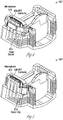
- FIGS. 4-5 illustrate views of a MID housing 300 including a microphone connection for a hearing assistance device, according to various embodiments of the present subject matter.
- a connection to a microphone 410 is made directly to the microphone pads.
- An LDS 3D MID technology is used to create metallized contacts 406, 506 that can also function as interconnects to other components, in various embodiments.
- the contacts 406, 506 are integral to the polymer contact fingers which provide one side of the connection.
- a retention band 412 of irradiated polymer (heat shrink) is applied over the microphone and fingers and heat applied to provide compression, in an embodiment.
- the retention is provided using a metal clip 514.
- Other retention mechanisms are possible without departing from the scope of the present subject matter.
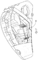
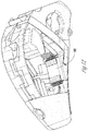
- FIGS. 6-7 illustrate views of a MID housing including programming connections for a hearing assistance device, according to various embodiments of the present subject matter.
- program connections are made using LDS 3D MID technologies to create metallized connection contacts 620 that can also function as interconnects to other components.
- the MID housing accepts a programming strip 622, in an embodiment.
- the connection contacts 620 are integral to the MID housing 300, in various embodiments.
- a battery drawer 730 has cam action that provides compression to ensure a proper connection, according to various embodiments.
- SLA stereolithography
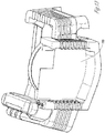
- FIGS. 8-10 illustrate views of a MID housing 300 including receiver connections for a hearing assistance device, according to various embodiments of the present subject matter.
- a microphone and a receiver To acoustically isolate a microphone and a receiver, no rigid connections are made to the receiver, in various embodiments. Flexible wires can be used and twisted to afford electromagnetic interference (EMI) protection as well, in various embodiments.
- LDS is used to provide a receptacle (via) 802.
- the receptacle 802 is lasered at the same time as a traces pattern.
- the receptacle 802 and custom plug 904 are smaller than currently available receiver connections.
- TWI pins 1006 are used with a custom mold to create a jack/connector, in various embodiments.
- the TWI plug includes wires 1002 to the receiver and a molded grip 1004, in various embodiments.
- Other direct insertion mechanisms are possible without departing from the scope of the present subject matter.
- the present subject matter provides for specific connection schemes for the UCM, components and devices to solderlessly connect to a unifying LDS structure.
- a system that incorporates this connector as well as solderless microphone, programming and accessory connections is provided.
- the present subject matter has application for both Standard and Custom hearing aids, and is superior to previous solutions in that it decreases the number of heat cycles, touch points and increases the ability to reuse more components.
- the present subject matter provides an injection molded plastic structure made with an LDS capable plastic. In various embodiments, it is included in an area of a larger part and the entire part is LDS capable.
- the UCM includes a ball grid array (BGA) format, in an embodiment.
- BGA ball grid array
- the UCM is reflowed to a simple 2 layer flex that is long enough to wrap up both sides of the UCM and partially across the back, in an embodiment.
- the flex along the sides and back has a specified thickness of pressure sensitive adhesive (0.005 thick in an embodiment) applied so that it holds the flex to the sides and back.
- the flex along the sides is designed to provide exposed connective traces that are finished with a corrosion resistant finish similar to standard PCB pad finishes, in various embodiments.
- the UCM with flex is inserted into the LDS structure, and the LDS structure is designed to have conductive pressure points that align with conductive traces on the UCM flex circuit, in various embodiments.
- the LDS conductive traces also have a corrosion resistant finish, in an embodiment.
- the design of the LDS structure also provides a compressive force on the UCM with flex, in various embodiments. Additional retention features can be incorporated as needed.
- FIGS. 11 and 12 show an example in a standard product application of the present subject matter, showing an LDS structure 1100 and a UCM 1200.
- FIGS. 13 and 14 show an embodiment of a custom application.
- This subject matter can be used as a means of connection without solder of the UCM.
- the connections made by the LDS structure to other solderless connection structures for microphone, six pin jack, programming, TC, switches, etc. can be used.
- the present subject matter provides for the ability to replace or salvage the UCM. In the case of a defective UCM, the time to replace would only be a fraction of the time that would be needed to rewire as in the case of a custom repair.
- the UCM can be removed without damage, in various embodiments.
- solderless connection to the UCM in standard products provides for the replacement of the UCM rather than having to replace the entire electronics system (the radio section and the entire high density flex, SMT switches, program jack etc.).
- the assembly time and component damage can be greatly reduced.
- the present subject matter provides for recovering and replacing of most the higher cost components possible without unnecessary damage or time required.
- the present subject matter can be used for standard fit as well as custom hearing aids, in various embodiments. Modules can be used in place of or in combination with flexible circuits, according to various embodiments. Benefits of the present subject matter include substantial assembly time and cost savings. Furthermore, the use of a common flexible circuit board for a variety of spine designs leads to less design time required for each hearing aid circuit style. The elimination of soldered wires as well as flexible circuit limbs leads to smaller hearing aids, in various embodiments.
- the wireless communications can include standard or nonstandard communications.
- standard wireless communications include link protocols including, but not limited to, BluetoothTM, IEEE 802.11 (wireless LANs), 802.15 (WPANs), 802.16 (WiMAX), cellular protocols including, but not limited to CDMA and GSM, ZigBee, and ultra-wideband (UWB) technologies.
- Such protocols support radio frequency communications and some support infrared communications.
- the present system is demonstrated as a radio system, it is possible that other forms of wireless communications can be used such as ultrasonic, optical, infrared, and others.
- the standards which can be used include past and present standards. It is also contemplated that future versions of these standards and new future standards may be employed without departing from the scope of the present subject matter.
- the wireless communications support a connection from other devices.
- Such connections include, but are not limited to, one or more mono or stereo connections or digital connections having link protocols including, but not limited to 802.3 (Ethernet), 802.4, 802.5, USB, SPI, PCM, ATM, Fibre-channel, Firewire or 1394, InfiniBand, or a native streaming interface.
- link protocols including, but not limited to 802.3 (Ethernet), 802.4, 802.5, USB, SPI, PCM, ATM, Fibre-channel, Firewire or 1394, InfiniBand, or a native streaming interface.
- such connections include all past and present link protocols. It is also contemplated that future versions of these protocols and new future standards may be employed without departing from the scope of the present subject matter.
- Hearing assistance devices typically include an enclosure or housing, a microphone, hearing assistance device electronics including processing electronics, and a speaker or receiver. It is understood that in various embodiments the receiver is optional.
- Antenna configurations may vary and may be included within an enclosure for the electronics or be external to an enclosure for the electronics. Thus, the examples set forth herein are intended to be demonstrative and not a limiting or exhaustive depiction of variations.
- any hearing assistance device may be used without departing from the scope and the devices depicted in the figures are intended to demonstrate the subject matter, but not in a limited, exhaustive, or exclusive sense. It is also understood that the present subject matter can be used with a device designed for use in the right ear or the left ear or both ears of the user.
- the hearing aids referenced in this patent application include a processor.
- the processor may be a digital signal processor (DSP), microprocessor, microcontroller, other digital logic, a separate analog and separate digital chip, or combinations thereof.
- DSP digital signal processor
- the processing of signals referenced in this application can be performed using the processor. Processing may be done in the digital domain, the analog domain, or combinations thereof. Processing may be done using subband processing techniques. Processing may be done with frequency domain or time domain approaches. Some processing may involve both frequency and time domain aspects. For brevity, in some examples drawings may omit certain blocks that perform frequency synthesis, frequency analysis, analog-to-digital conversion, digital-to-analog conversion, amplification, audio decoding, and certain types of filtering and processing.
- the processor is adapted to perform instructions stored in memory which may or may not be explicitly shown.
- Various types of memory may be used, including volatile and nonvolatile forms of memory.
- instructions are performed by the processor to perform a number of signal processing tasks.
- analog components are in communication with the processor to perform signal tasks, such as microphone reception, or receiver sound embodiments (i.e., in applications where such transducers are used).
- signal tasks such as microphone reception, or receiver sound embodiments (i.e., in applications where such transducers are used).
- different realizations of the block diagrams, circuits, and processes set forth herein may occur without departing from the scope of the present subject matter.
- hearing assistance devices including hearing aids, including but not limited to, behind-the-ear (BTE), in-the-ear (ITE), in-the-canal (ITC), receiver-in-canal (RIC), completely-in-the-canal (CIC) or invisible-in-canal (IIC) type hearing aids.
- BTE behind-the-ear
- ITE in-the-ear
- ITC in-the-canal
- RIC receiver-in-canal
- CIC completely-in-the-canal
- IIC invisible-in-canal
- hearing assistance devices including but not limited to, behind-the-ear (BTE), in-the-ear (ITE), in-the-canal (ITC), receiver-in-canal (RIC), completely-in-the-canal (CIC) or invisible-in-canal (IIC) type hearing aids.
- BTE behind-the-ear
- ITE in-the-ear
- ITC in-the-canal
- RIC receiver-in-canal
- the present subject matter can also be used in hearing assistance devices generally, such as cochlear implant type hearing devices and such as deep insertion devices having a transducer, such as a receiver or microphone, whether custom fitted, standard, open fitted or occlusive fitted. It is understood that other hearing assistance devices not expressly stated herein may be used in conjunction with the present subject matter.
Description
- This document relates generally to hearing assistance systems and more particularly to methods and apparatus for solderless module connectors for hearing assistance devices.
- Hearing assistance devices, such as hearing aids, include, but are not limited to, devices for use in the ear, in the ear canal, completely in the canal, and behind the ear. Such devices have been developed to ameliorate the effects of hearing losses in individuals. Hearing deficiencies can range from deafness to hearing losses where the individual has impairment responding to different frequencies of sound or to being able to differentiate sounds occurring simultaneously.
- The hearing aid in its most elementary form usually provides for auditory correction through the amplification and filtering of sound. Hearing aids typically include an enclosure or housing, a microphone, hearing assistance device electronics including processing electronics, and a speaker or receiver. Existing hearing aid circuits and bodies are hand assembled, use individual wires for interconnects, and use a messy and time-consuming soldering process.
- Accordingly, there is a need in the art for methods and apparatus for improved assembly for hearing assistance devices.
-
EP2063694A1 discloses a voice output unit which includes a power source; a signal processing module which processes voice signals received from an external source and amplifies the processed voice signals processed; a speaker module transmitting the amplified voice signals as voice signals; and a stereoscopic circuit board on which the power source, signal processing module, and speaker module are assembled, and includes electrodes which are in electric contact with electrodes of the foregoing components. -
US4116517A discloses a flexible printed circuit electrically connected to a printed circuit board without the use of intermediate conducting contact elements. The flexible printed circuit has conductive strips thereon each terminating in a conductive pad. The pads and the areas of the insulation sheet of the circuit underlying the pads are deformed to provide contact projections defining cavities therebelow. A backing layer of elastomeric material underlying the insulation sheet embodies points which extend into the cavities. - Disclosed herein, among other things, are systems and methods for solderless module connectors for hearing assistance devices. One aspect of the present subject matter includes a method of assembling a hearing assistance device, the method comprising: providing a structure including a laser-direct structuring (LDS) portion; inserting a flexible universal circuit module (UCM) having conductive surface traces and elastomeric backing into the structure, wherein the UCM includes a layered flex circuit wrapped on at least one side and the flex circuit includes a pressure sensitive adhesive to adhere the flex circuit to the UCM, wherein the UCM is configured for a replaceable connection and includes electronics for hearing assistance; and electrically connecting the UCM to the LDS portion using direct compression without the use of wires or solder.
- Another aspect of the present subject matter includes a hearing assistance device comprising a structure including a laser-direct structuring (LDS) portion; and a flexible universal circuit module (UCM) having conductive surface traces and elastomeric backing, the flexible circuit module configured to be inserted into the structure; wherein the UCM is configured to electrically connect to the LDS portion using direct compression without the use of wires or solder, wherein the UCM includes a layered flex circuit wrapped on at least one side and the flex circuit includes a pressure sensitive adhesive to adhere the flex circuit to the UCM, and wherein the UCM is configured for a replaceable connection and includes electronics for hearing assistance.
- This Summary is an overview of some of the teachings of the present application and not intended to be an exclusive or exhaustive treatment of the present subject matter. Further details about the present subject matter are found in the detailed description and appended claims. The scope of the present invention is defined by the appended claims and their legal equivalents.
-
-
FIG. 1 shows a block diagram of a hearing assistance device, according to various embodiments of the present subject matter. -
FIGS. 2A-2B illustrate views of a flexible circuit module for a hearing assistance device, according to various embodiments of the present subject matter. -
FIGS. 3A-3C illustrate views of a MID housing including conductive surface traces for a hearing assistance device, according to various embodiments of the present subject matter. -
FIGS. 4-5 illustrate views of a MID housing including a microphone connection for a hearing assistance device, according to various embodiments of the present subject matter. -
FIGS. 6-7 illustrate views of a MID housing including programming connections for a hearing assistance device, according to various embodiments of the present subject matter. -
FIGS. 8-10 illustrate views of a MID housing including receiver connections for a hearing assistance device, according to various embodiments of the present subject matter. -
FIGS. 11-12 illustrate views of a standard product application of a UCM connection, according to various embodiments of the present subject matter. -
FIGS. 13-14 illustrate views of a custom product application of a UCM connection, according to various embodiments of the present subject matter. - The following detailed description of the present subject matter refers to subject matter in the accompanying drawings which show, by way of illustration, specific aspects and embodiments in which the present subject matter may be practiced. These embodiments are described in sufficient detail to enable those skilled in the art to practice the present subject matter. References to "an", "one", or "various" embodiments in this disclosure are not necessarily to the same embodiment, and such references contemplate more than one embodiment. The following detailed description is demonstrative and not to be taken in a limiting sense. The scope of the present subject matter is defined by the appended claims, along with the full scope of legal equivalents to which such claims are entitled.
- The present detailed description will discuss hearing assistance devices using the example of hearing aids. Hearing aids are only one type of hearing assistance device. Other hearing assistance devices include, but are not limited to, those in this document. It is understood that their use in the description is intended to demonstrate the present subject matter, but not in a limited or exclusive or exhaustive sense. Hearing aids typically include an enclosure or housing, a microphone, hearing assistance device electronics including processing electronics, and a speaker or receiver. Hearing assistance devices may include a power source, such as a battery. In various embodiments, the battery may be rechargeable. In various embodiments multiple energy sources may be employed. It is understood that in various embodiments the microphone is optional. It is understood that in various embodiments the receiver is optional. It is understood that variations in communications protocols, antenna configurations, and combinations of components may be employed without departing from the scope of the present subject matter. Antenna configurations may vary and may be included within an enclosure for the electronics or be external to an enclosure for the electronics. Thus, the examples set forth herein are intended to be demonstrative and not a limiting or exhaustive depiction of variations. Existing hearing aid circuits and bodies are hand assembled, use individual wires for interconnects, and use a messy and time-consuming soldering process.
- Disclosed herein, among other things, are systems and methods for solderless module connectors for hearing assistance devices. One aspect of the present subject matter includes a method of assembling a hearing assistance device. According to various embodiments, the method includes providing a structure including a laser-direct structuring (LDS) portion, and inserting a flexible universal circuit module (UCM) having conductive surface traces and elastomeric backing into the structure. The UCM is electrically connected to the LDS portion using direct compression without the use of wires or solder, according to various embodiments. One aspect of the present subject matter includes a hearing assistance device. According to various embodiments, the hearing assistance device includes a structure including a laser-direct structuring (LDS) portion, and a flexible universal circuit module (UCM) having conductive surface traces and elastomeric backing, the flexible circuit module configured to be inserted into the structure. In various embodiments, the UCM is configured to electrically connect to the LDS portion using direct compression without the use of wires or solder.
- Disclosed herein, among other things, are systems and methods for solderless assembly for hearing assistance devices. One aspect of the present subject matter includes a hearing assistance device. According to various embodiments, the hearing assistance device includes a LDS housing and a flexible circuit module having conductive surface traces and also has elastomeric backing, the flexible circuit module configured to be inserted into the housing. One or more hearing assistance electronic modules are configured to connect to the flexible circuit module using direct compression without the use of wires or solder, in various embodiments. The present subject matter uses LDS which is a type of molded interconnect device (MID) technology that combines injection-molded thermoplastic parts with integrated electronic circuit traces using selective metallization. In LDS, thermoplastic parts are doped with a metal-plastic additive that can be activated using a laser. The present subject matter contemplates any and all types of LDS technology for implementation of the solderless hearing assistance device system.
-
FIG. 1 shows a block diagram of ahearing assistance device 100 according to one embodiment of the present subject matter. In this exemplary embodiment thehearing assistance device 100 includes hearing assistance electronics such as aprocessor 110 and at least onepower supply 112. In one embodiment, theprocessor 110 is a digital signal processor (DSP). In one embodiment, theprocessor 110 is a microprocessor. In one embodiment, theprocessor 110 is a microcontroller. In one embodiment, theprocessor 110 is a combination of components. It is understood that in various embodiments, theprocessor 110 can be realized in a configuration of hardware or firmware, or a combination of both. In various embodiments, theprocessor 110 is programmed to provide different processing functions depending on the signals sensed from themicrophone 130. In hearing aid embodiments,microphone 130 is configured to provide signals to theprocessor 110 which are processed and played to the wearer with speaker 140 (also known as a "receiver" in the hearing aid art). - Other inputs may be used in combination with the microphone. For example, signals from a number of different signal sources can be detected using the teachings provided herein, such as audio information from a FM radio receiver, signals from a BLUETOOTH or other wireless receiver, signals from a magnetic induction source, signals from a wired audio connection, signals from a cellular phone, or signals from any other signal source.
- The present subject matter overcomes several problems encountered in assembling hearing assistance devices and their subcomponents. One of these problems is the time consuming, messy process of hand assembly and soldering. Another problem overcome by the present subject matter is the lengthy design time of each hearing aid circuit. Finally, the overall cost of materials, such as high density flex, is reduced by the present subject matter.
- Currently, the assembly of flexible circuits into hearing aids can be complicated. Once the flexible circuit is inserted into the spine, each limb of the circuit must be bent down and connected to another component. The connection is currently made by direct soldering, such as to a battery contact, or a wire must be soldered to the flexible circuit pad and then run to a second component, such as a push button or microphone. Currently the primary method of soldering wire connections is hand soldering, and this process alone contributes significantly to the time required to make a custom hearing assistance product. In addition, the use of heat in the soldering process can cause component and circuit damage both during assembly and repair. Thus, the current method of using wires and soldering for hearing assistance device component interconnects consumes labor, time, additional parts (wires and additional subassemblies), additional parts cost, additional connection points and increased system volume. It also provides a difficult and messy repair process. Furthermore, the wires must be placed over the spine, taking up valuable space, and can be pulled or broken during the process.
- Previous solutions to the hand soldering and assembly steps include attempts to reduce the number of wires necessary in standard hearing aid designs, specifically by replacing them with additional flexible circuit limbs. The addition of more limbs leads to even more complex and abstractly shaped circuits. This leads to fewer circuits per panel and consequently a larger numbers of costly circuit panels. The past solutions to reduce the time and effort related to designing flexible circuits have focused on designing a common flexible circuit board between products. A common flexible circuit board is difficult to accomplish due to the diverse hearing aid design shapes, electrical requirements and location of connection points. Previously, when a common design has been successfully developed it has required the removal of a circuit limb for each hearing aid design. This results in wasted flexible circuit material as well as wasted space per panel. There are also efforts made to redesign current product flexible circuit designs in order to fit more circuits per panel. These attempts result in only a few more circuits fitting onto the panel and the cost savings is minimal. This also results in even more circuit design time spent per hearing aid design.
- The present subject matter provides a hearing aid circuit and body that can be assembled without the need for solder or conductive epoxy. The present subject matter is unique in that it provides a method of assembling a hearing aid circuit to the spine and other components without the need of solder or conductive epoxy by utilizing a high density flexible circuit without wires in combination with a low density spine or housing, in various embodiments. Various embodiments of the present subject matter include a solderless microphone connection, solderless DSP module connection, solderless integration of a receiver jack, and solderless integrated programming interface. The present subject matter improves upon previous solutions because it does not require the addition of more wires or flexible circuit limbs. In various embodiments, the method of the present subject matter leads to higher yields of hearing aid components since they are not subjected to soldering temperatures. Additionally, the design time and effort associated with developing new hearing aids is reduced, making assembly and repair substantially easier and quicker, and eliminating the need for circuit limbs leading to more circuits per panel.
- According to various embodiments, the present subject matter includes four types of solderless assembly connection. The connections are made via direct compression where the MID conductors form a connection with the flex without intermediary materials such as solder or conductive epoxy. The drawings illustrate a custom hearing aid application, but one of skill in the art would understand that the present subject matter is equally applicable to other types of hearing aids, such as those with a standard spine.
-
FIGS. 2A-2B illustrate views of a flexible circuit module for a hearing assistance device, according to various embodiments of the present subject matter. ADSP module 200 includes an integratedflex connection area 202 having exposed traces. The exposed traces include Nickel Gold plating, in an embodiment. Other types of traces can be used without departing from the scope of the present subject matter. The traces are located on the edges of the module, in various embodiments. Anelastomeric material 204 is located between the flex and the module sides in various embodiments, providing pressure to ensure proper connections. -
FIGS. 3A-3C illustrate views of aMID housing 300 including conductive surface traces for a hearing assistance device, according to various embodiments of the present subject matter. The electrical connection with theflex connection area 302 is made with plastic fingers withtraces 306 that have been processed using LDS three-dimensional (3D) molded interconnect device (MID) technologies to provide both the connection point as well as interconnection to other components, according to various embodiments. Theelastomeric material 204 located between the flex and the module sides provides pressure to ensure proper connections, in various embodiments. -
FIGS. 4-5 illustrate views of aMID housing 300 including a microphone connection for a hearing assistance device, according to various embodiments of the present subject matter. In various embodiments, a connection to amicrophone 410 is made directly to the microphone pads. An LDS 3D MID technology is used to create metallizedcontacts 406, 506 that can also function as interconnects to other components, in various embodiments. According to various embodiments, thecontacts 406, 506 are integral to the polymer contact fingers which provide one side of the connection. Aretention band 412 of irradiated polymer (heat shrink) is applied over the microphone and fingers and heat applied to provide compression, in an embodiment. In another embodiment, the retention is provided using ametal clip 514. Other retention mechanisms are possible without departing from the scope of the present subject matter. -
FIGS. 6-7 illustrate views of a MID housing including programming connections for a hearing assistance device, according to various embodiments of the present subject matter. In various embodiments, program connections are made using LDS 3D MID technologies to createmetallized connection contacts 620 that can also function as interconnects to other components. The MID housing accepts aprogramming strip 622, in an embodiment. Theconnection contacts 620 are integral to theMID housing 300, in various embodiments. Abattery drawer 730 has cam action that provides compression to ensure a proper connection, according to various embodiments. In conjunction with a stereolithography (SLA) shell with module retention features, any component can be replaced and sent to a central reprocessing point for recovery and possible reuse, all without component or shell damage. -
FIGS. 8-10 illustrate views of aMID housing 300 including receiver connections for a hearing assistance device, according to various embodiments of the present subject matter. To acoustically isolate a microphone and a receiver, no rigid connections are made to the receiver, in various embodiments. Flexible wires can be used and twisted to afford electromagnetic interference (EMI) protection as well, in various embodiments. LDS is used to provide a receptacle (via) 802. In various embodiments, thereceptacle 802 is lasered at the same time as a traces pattern. In one embodiment, thereceptacle 802 and custom plug 904 are smaller than currently available receiver connections. In order to provide compression in the connection, twisted wire interconnect (TWI) pins 1006 are used with a custom mold to create a jack/connector, in various embodiments. The TWI plug includeswires 1002 to the receiver and a moldedgrip 1004, in various embodiments. Other direct insertion mechanisms are possible without departing from the scope of the present subject matter. - The present subject matter provides for specific connection schemes for the UCM, components and devices to solderlessly connect to a unifying LDS structure. In various embodiments, a system that incorporates this connector as well as solderless microphone, programming and accessory connections is provided. The present subject matter has application for both Standard and Custom hearing aids, and is superior to previous solutions in that it decreases the number of heat cycles, touch points and increases the ability to reuse more components. The present subject matter provides an injection molded plastic structure made with an LDS capable plastic. In various embodiments, it is included in an area of a larger part and the entire part is LDS capable. The UCM includes a ball grid array (BGA) format, in an embodiment. The UCM is reflowed to a simple 2 layer flex that is long enough to wrap up both sides of the UCM and partially across the back, in an embodiment. The flex along the sides and back has a specified thickness of pressure sensitive adhesive (0.005 thick in an embodiment) applied so that it holds the flex to the sides and back. The flex along the sides is designed to provide exposed connective traces that are finished with a corrosion resistant finish similar to standard PCB pad finishes, in various embodiments. The UCM with flex is inserted into the LDS structure, and the LDS structure is designed to have conductive pressure points that align with conductive traces on the UCM flex circuit, in various embodiments. The LDS conductive traces also have a corrosion resistant finish, in an embodiment. The design of the LDS structure also provides a compressive force on the UCM with flex, in various embodiments. Additional retention features can be incorporated as needed.
-
FIGS. 11 and12 show an example in a standard product application of the present subject matter, showing anLDS structure 1100 and aUCM 1200.FIGS. 13 and14 show an embodiment of a custom application. This subject matter can be used as a means of connection without solder of the UCM. In various embodiments the connections made by the LDS structure to other solderless connection structures for microphone, six pin jack, programming, TC, switches, etc., can be used. The present subject matter provides for the ability to replace or salvage the UCM. In the case of a defective UCM, the time to replace would only be a fraction of the time that would be needed to rewire as in the case of a custom repair. The UCM can be removed without damage, in various embodiments. Additionally, using the solderless connection to the UCM in standard products provides for the replacement of the UCM rather than having to replace the entire electronics system (the radio section and the entire high density flex, SMT switches, program jack etc.). When in conjunction with other solderless connectors made using LDS, the assembly time and component damage can be greatly reduced. The present subject matter provides for recovering and replacing of most the higher cost components possible without unnecessary damage or time required. - The present subject matter can be used for standard fit as well as custom hearing aids, in various embodiments. Modules can be used in place of or in combination with flexible circuits, according to various embodiments. Benefits of the present subject matter include substantial assembly time and cost savings. Furthermore, the use of a common flexible circuit board for a variety of spine designs leads to less design time required for each hearing aid circuit style. The elimination of soldered wires as well as flexible circuit limbs leads to smaller hearing aids, in various embodiments.
- Various embodiments of the present subject matter support wireless communications with a hearing assistance device. In various embodiments the wireless communications can include standard or nonstandard communications. Some examples of standard wireless communications include link protocols including, but not limited to, Bluetooth™, IEEE 802.11 (wireless LANs), 802.15 (WPANs), 802.16 (WiMAX), cellular protocols including, but not limited to CDMA and GSM, ZigBee, and ultra-wideband (UWB) technologies. Such protocols support radio frequency communications and some support infrared communications. Although the present system is demonstrated as a radio system, it is possible that other forms of wireless communications can be used such as ultrasonic, optical, infrared, and others. It is understood that the standards which can be used include past and present standards. It is also contemplated that future versions of these standards and new future standards may be employed without departing from the scope of the present subject matter.
- The wireless communications support a connection from other devices. Such connections include, but are not limited to, one or more mono or stereo connections or digital connections having link protocols including, but not limited to 802.3 (Ethernet), 802.4, 802.5, USB, SPI, PCM, ATM, Fibre-channel, Firewire or 1394, InfiniBand, or a native streaming interface. In various embodiments, such connections include all past and present link protocols. It is also contemplated that future versions of these protocols and new future standards may be employed without departing from the scope of the present subject matter.
- It is understood that variations in communications protocols, antenna configurations, and combinations of components may be employed without departing from the scope of the present subject matter. Hearing assistance devices typically include an enclosure or housing, a microphone, hearing assistance device electronics including processing electronics, and a speaker or receiver. It is understood that in various embodiments the receiver is optional. Antenna configurations may vary and may be included within an enclosure for the electronics or be external to an enclosure for the electronics. Thus, the examples set forth herein are intended to be demonstrative and not a limiting or exhaustive depiction of variations.
- It is further understood that any hearing assistance device may be used without departing from the scope and the devices depicted in the figures are intended to demonstrate the subject matter, but not in a limited, exhaustive, or exclusive sense. It is also understood that the present subject matter can be used with a device designed for use in the right ear or the left ear or both ears of the user.
- It is understood that the hearing aids referenced in this patent application include a processor. The processor may be a digital signal processor (DSP), microprocessor, microcontroller, other digital logic, a separate analog and separate digital chip, or combinations thereof. The processing of signals referenced in this application can be performed using the processor. Processing may be done in the digital domain, the analog domain, or combinations thereof. Processing may be done using subband processing techniques. Processing may be done with frequency domain or time domain approaches. Some processing may involve both frequency and time domain aspects. For brevity, in some examples drawings may omit certain blocks that perform frequency synthesis, frequency analysis, analog-to-digital conversion, digital-to-analog conversion, amplification, audio decoding, and certain types of filtering and processing. In various embodiments the processor is adapted to perform instructions stored in memory which may or may not be explicitly shown. Various types of memory may be used, including volatile and nonvolatile forms of memory. In various embodiments, instructions are performed by the processor to perform a number of signal processing tasks. In such embodiments, analog components are in communication with the processor to perform signal tasks, such as microphone reception, or receiver sound embodiments (i.e., in applications where such transducers are used). In various embodiments, different realizations of the block diagrams, circuits, and processes set forth herein may occur without departing from the scope of the present subject matter.
- The present subject matter is demonstrated for hearing assistance devices, including hearing aids, including but not limited to, behind-the-ear (BTE), in-the-ear (ITE), in-the-canal (ITC), receiver-in-canal (RIC), completely-in-the-canal (CIC) or invisible-in-canal (IIC) type hearing aids. It is understood that behind-the-ear type hearing aids may include devices that reside substantially behind the ear or over the ear. Such devices may include hearing aids with receivers associated with the electronics portion of the behind-the-ear device, or hearing aids of the type having receivers in the ear canal of the user, including but not limited to receiver-in-canal (RIC) or receiver-in-the-ear (RITE) designs. The present subject matter can also be used in hearing assistance devices generally, such as cochlear implant type hearing devices and such as deep insertion devices having a transducer, such as a receiver or microphone, whether custom fitted, standard, open fitted or occlusive fitted. It is understood that other hearing assistance devices not expressly stated herein may be used in conjunction with the present subject matter.
- It is to be understood that the above description is intended to be illustrative, and not restrictive. The scope of the present subject matter should be determined with reference to the appended claims, along with the full scope of legal equivalents to which such claims are entitled.
Claims (13)
- A method of assembling a hearing assistance device, the method comprising:providing a structure (1100) including a laser-direct structuring, LDS, portion;inserting a flexible universal circuit module, UCM, (1200) having conductive surface traces and elastomeric backing into the structure (1100), wherein the UCM includes a layered flex circuit wrapped on at least one side and the flex circuit includes a pressure sensitive adhesive to adhere the flex circuit to the UCM (1200), wherein the UCM (1200) is configured for a replaceable connection and includes electronics for hearing assistance; andelectrically connecting the UCM (1200) to the LDS portion using direct compression without the use of wires or solder.
- The method of claim 1, wherein the structure includes multiple LDS portions configured to electrically connect to additional components without wires or solder.
- The method of claim 1 or claim 2, wherein the UCM (1200) includes an integrated flex connection on an edge of the UCM (1200), the integrated flex connection including exposed traces.
- The method of claim 1 or claim 2, wherein the UCM (1200) includes a ball grid array (BGA) portion.
- The method of claim 1, wherein at least a portion of the flex circuit includes exposed conductive traces finished with a corrosion resistant material.
- The method of claim 5, wherein the LDS portion includes conductive pressure points that are configured to align with the exposed conductive traces, and wherein the structure (1100) is configured to provide a compressive force on the UCM (1200) with flex.
- The method of claim 6, wherein the conductive pressure points include a corrosion resistant finish.
- A hearing assistance device, comprisinga structure (1100) including a laser-direct structuring, LDS, portion; anda flexible universal circuit module, UCM, (1200) having conductive surface traces and elastomeric backing, the flexible circuit module configured to be inserted into the structure (1100);wherein the UCM (1200) is configured to electrically connect to the LDS portion using direct compression without the use of wires or solder, wherein the UCM (1200) includes a layered flex circuit wrapped on at least one side and the flex circuit includes a pressure sensitive adhesive to adhere the flex circuit to the UCM (1200), and wherein the UCM (1200) is configured for a replaceable connection and includes electronics for hearing assistance.
- The device of claim 8, wherein the hearing assistance device includes a standard product assembly.
- The device of claim 9, wherein the hearing assistance device includes a custom shell.
- The device of any of clam 8 through claim 10, wherein the hearing assistance device includes a hearing aid.
- The device of claim 11, wherein the hearing aid includes an in-the-ear (ITE) hearing aid.
- The device of claim 11, wherein the hearing aid includes a behind-the-ear (BTE) hearing aid.
Applications Claiming Priority (1)
| Application Number | Priority Date | Filing Date | Title |
|---|---|---|---|
| US14/692,849 US9906879B2 (en) | 2013-11-27 | 2015-04-22 | Solderless module connector for a hearing assistance device assembly |
Publications (2)
| Publication Number | Publication Date |
|---|---|
| EP3086576A1 EP3086576A1 (en) | 2016-10-26 |
| EP3086576B1 true EP3086576B1 (en) | 2021-09-01 |
Family
ID=55952960
Family Applications (1)
| Application Number | Title | Priority Date | Filing Date |
|---|---|---|---|
| EP16166704.3A Active EP3086576B1 (en) | 2015-04-22 | 2016-04-22 | Solderless module connector for a hearing assistance device assembly |
Country Status (1)
| Country | Link |
|---|---|
| EP (1) | EP3086576B1 (en) |
Citations (1)
| Publication number | Priority date | Publication date | Assignee | Title |
|---|---|---|---|---|
| JPH0766533A (en) * | 1993-08-26 | 1995-03-10 | Matsushita Electric Works Ltd | Manufacture circuit board |
Family Cites Families (3)
| Publication number | Priority date | Publication date | Assignee | Title |
|---|---|---|---|---|
| US4116517A (en) * | 1976-04-15 | 1978-09-26 | International Telephone And Telegraph Corporation | Flexible printed circuit and electrical connection therefor |
| JP2008091554A (en) * | 2006-09-29 | 2008-04-17 | Matsushita Electric Works Ltd | Speech output equipment |
| US9913052B2 (en) * | 2013-11-27 | 2018-03-06 | Starkey Laboratories, Inc. | Solderless hearing assistance device assembly and method |
-
2016
- 2016-04-22 EP EP16166704.3A patent/EP3086576B1/en active Active
Patent Citations (2)
| Publication number | Priority date | Publication date | Assignee | Title |
|---|---|---|---|---|
| JPH0766533A (en) * | 1993-08-26 | 1995-03-10 | Matsushita Electric Works Ltd | Manufacture circuit board |
| US5494781A (en) * | 1993-08-26 | 1996-02-27 | Matsushita Electric Works, Ltd. | Method for manufacturing printed circuit board |
Non-Patent Citations (1)
| Title |
|---|
| MARK FINSTAD ET AL: "The glue that binds: thoughts on pressure-sensitive and thermosetting adhesives.", PRINTED CIRCUIT DESIGN & FAB, 1 July 2013 (2013-07-01), XP055573996, Retrieved from the Internet <URL:https://www.thefreelibrary.com/_/print/PrintArticle.aspx?id=348313847> [retrieved on 20190325] * |
Also Published As
| Publication number | Publication date |
|---|---|
| EP3086576A1 (en) | 2016-10-26 |
Similar Documents
| Publication | Publication Date | Title |
|---|---|---|
| US9906879B2 (en) | Solderless module connector for a hearing assistance device assembly | |
| EP2879407B1 (en) | Solderless hearing assistance device assembly and method | |
| US20230156414A1 (en) | Radio frequency antenna for an in-the-ear hearing device | |
| EP2827613B1 (en) | System and method for embedding conductive traces into hearing assistance device housings | |
| US9474154B2 (en) | Reflow solderable flexible circuit board — to — flexible circuit board connector reinforcement | |
| EP2663097B1 (en) | Flex connector for a hearing assistance device | |
| EP3116240B1 (en) | Hearing device with detachable speaker unit | |
| EP2503797B1 (en) | Compact programming block connector for hearing assistance devices | |
| EP3188509A1 (en) | Hearing assistance device earhook and sound tube antennas | |
| WO2008041479A1 (en) | Audio output device | |
| EP2424275B1 (en) | A listening device adapted for establishing an electric connection to an external device using electrically conductive parts of one or more components of the listening device | |
| EP3086576B1 (en) | Solderless module connector for a hearing assistance device assembly | |
| CN104396352A (en) | Injection moulded circuit carrier having integrated circuit board | |
| EP2942979B1 (en) | Increasing antenna performance for wireless hearing assistance devices | |
| WO2014179613A1 (en) | Increasing antenna performance for wireless hearing assistance devices | |
| EP2324643B1 (en) | Hearing aid faceplate arrangement | |
| US8548183B2 (en) | Hearing device with individually aligned electronic component and production method | |
| US20180317032A1 (en) | Method for producing a supporting frame of a hearing aid, supporting frame and hearing aid | |
| JPWO2019197568A5 (en) | ||
| CN114979879A (en) | Hearing device comprising a battery module and method of manufacturing a battery module for a hearing device |
Legal Events
| Date | Code | Title | Description |
|---|---|---|---|
| PUAI | Public reference made under article 153(3) epc to a published international application that has entered the european phase |
Free format text: ORIGINAL CODE: 0009012 |
|
| AK | Designated contracting states |
Kind code of ref document: A1 Designated state(s): AL AT BE BG CH CY CZ DE DK EE ES FI FR GB GR HR HU IE IS IT LI LT LU LV MC MK MT NL NO PL PT RO RS SE SI SK SM TR |
|
| AX | Request for extension of the european patent |
Extension state: BA ME |
|
| STAA | Information on the status of an ep patent application or granted ep patent |
Free format text: STATUS: THE APPLICATION HAS BEEN PUBLISHED |
|
| 17P | Request for examination filed |
Effective date: 20170426 |
|
| RBV | Designated contracting states (corrected) |
Designated state(s): AL AT BE BG CH CY CZ DE DK EE ES FI FR GB GR HR HU IE IS IT LI LT LU LV MC MK MT NL NO PL PT RO RS SE SI SK SM TR |
|
| STAA | Information on the status of an ep patent application or granted ep patent |
Free format text: STATUS: REQUEST FOR EXAMINATION WAS MADE |
|
| STAA | Information on the status of an ep patent application or granted ep patent |
Free format text: STATUS: EXAMINATION IS IN PROGRESS |
|
| 17Q | First examination report despatched |
Effective date: 20190401 |
|
| RAP1 | Party data changed (applicant data changed or rights of an application transferred) |
Owner name: STARKEY LABORATORIES, INC. |
|
| RIN1 | Information on inventor provided before grant (corrected) |
Inventor name: DZARNOSKI, JOHN Inventor name: PRCHAL, DAVID Inventor name: JOHANSSON, SUSIE |
|
| STAA | Information on the status of an ep patent application or granted ep patent |
Free format text: STATUS: EXAMINATION IS IN PROGRESS |
|
| GRAP | Despatch of communication of intention to grant a patent |
Free format text: ORIGINAL CODE: EPIDOSNIGR1 |
|
| STAA | Information on the status of an ep patent application or granted ep patent |
Free format text: STATUS: GRANT OF PATENT IS INTENDED |
|
| RIC1 | Information provided on ipc code assigned before grant |
Ipc: H01R 13/24 20060101ALN20210322BHEP Ipc: H01R 12/71 20110101ALN20210322BHEP Ipc: H01R 12/70 20110101ALI20210322BHEP Ipc: H04R 25/00 20060101AFI20210322BHEP |
|
| INTG | Intention to grant announced |
Effective date: 20210413 |
|
| GRAS | Grant fee paid |
Free format text: ORIGINAL CODE: EPIDOSNIGR3 |
|
| GRAA | (expected) grant |
Free format text: ORIGINAL CODE: 0009210 |
|
| STAA | Information on the status of an ep patent application or granted ep patent |
Free format text: STATUS: THE PATENT HAS BEEN GRANTED |
|
| AK | Designated contracting states |
Kind code of ref document: B1 Designated state(s): AL AT BE BG CH CY CZ DE DK EE ES FI FR GB GR HR HU IE IS IT LI LT LU LV MC MK MT NL NO PL PT RO RS SE SI SK SM TR |
|
| REG | Reference to a national code |
Ref country code: GB Ref legal event code: FG4D |
|
| REG | Reference to a national code |
Ref country code: CH Ref legal event code: EP Ref country code: AT Ref legal event code: REF Ref document number: 1427529 Country of ref document: AT Kind code of ref document: T Effective date: 20210915 |
|
| REG | Reference to a national code |
Ref country code: DE Ref legal event code: R096 Ref document number: 602016062961 Country of ref document: DE |
|
| REG | Reference to a national code |
Ref country code: IE Ref legal event code: FG4D |
|
| REG | Reference to a national code |
Ref country code: LT Ref legal event code: MG9D |
|
| REG | Reference to a national code |
Ref country code: NL Ref legal event code: MP Effective date: 20210901 |
|
| PG25 | Lapsed in a contracting state [announced via postgrant information from national office to epo] |
Ref country code: HR Free format text: LAPSE BECAUSE OF FAILURE TO SUBMIT A TRANSLATION OF THE DESCRIPTION OR TO PAY THE FEE WITHIN THE PRESCRIBED TIME-LIMIT Effective date: 20210901 Ref country code: RS Free format text: LAPSE BECAUSE OF FAILURE TO SUBMIT A TRANSLATION OF THE DESCRIPTION OR TO PAY THE FEE WITHIN THE PRESCRIBED TIME-LIMIT Effective date: 20210901 Ref country code: SE Free format text: LAPSE BECAUSE OF FAILURE TO SUBMIT A TRANSLATION OF THE DESCRIPTION OR TO PAY THE FEE WITHIN THE PRESCRIBED TIME-LIMIT Effective date: 20210901 Ref country code: LT Free format text: LAPSE BECAUSE OF FAILURE TO SUBMIT A TRANSLATION OF THE DESCRIPTION OR TO PAY THE FEE WITHIN THE PRESCRIBED TIME-LIMIT Effective date: 20210901 Ref country code: BG Free format text: LAPSE BECAUSE OF FAILURE TO SUBMIT A TRANSLATION OF THE DESCRIPTION OR TO PAY THE FEE WITHIN THE PRESCRIBED TIME-LIMIT Effective date: 20211201 Ref country code: NO Free format text: LAPSE BECAUSE OF FAILURE TO SUBMIT A TRANSLATION OF THE DESCRIPTION OR TO PAY THE FEE WITHIN THE PRESCRIBED TIME-LIMIT Effective date: 20211201 Ref country code: ES Free format text: LAPSE BECAUSE OF FAILURE TO SUBMIT A TRANSLATION OF THE DESCRIPTION OR TO PAY THE FEE WITHIN THE PRESCRIBED TIME-LIMIT Effective date: 20210901 Ref country code: FI Free format text: LAPSE BECAUSE OF FAILURE TO SUBMIT A TRANSLATION OF THE DESCRIPTION OR TO PAY THE FEE WITHIN THE PRESCRIBED TIME-LIMIT Effective date: 20210901 |
|
| REG | Reference to a national code |
Ref country code: AT Ref legal event code: MK05 Ref document number: 1427529 Country of ref document: AT Kind code of ref document: T Effective date: 20210901 |
|
| PG25 | Lapsed in a contracting state [announced via postgrant information from national office to epo] |
Ref country code: PL Free format text: LAPSE BECAUSE OF FAILURE TO SUBMIT A TRANSLATION OF THE DESCRIPTION OR TO PAY THE FEE WITHIN THE PRESCRIBED TIME-LIMIT Effective date: 20210901 Ref country code: LV Free format text: LAPSE BECAUSE OF FAILURE TO SUBMIT A TRANSLATION OF THE DESCRIPTION OR TO PAY THE FEE WITHIN THE PRESCRIBED TIME-LIMIT Effective date: 20210901 Ref country code: GR Free format text: LAPSE BECAUSE OF FAILURE TO SUBMIT A TRANSLATION OF THE DESCRIPTION OR TO PAY THE FEE WITHIN THE PRESCRIBED TIME-LIMIT Effective date: 20211202 |
|
| PG25 | Lapsed in a contracting state [announced via postgrant information from national office to epo] |
Ref country code: AT Free format text: LAPSE BECAUSE OF FAILURE TO SUBMIT A TRANSLATION OF THE DESCRIPTION OR TO PAY THE FEE WITHIN THE PRESCRIBED TIME-LIMIT Effective date: 20210901 |
|
| PGFP | Annual fee paid to national office [announced via postgrant information from national office to epo] |
Ref country code: GB Payment date: 20220308 Year of fee payment: 7 |
|
| PG25 | Lapsed in a contracting state [announced via postgrant information from national office to epo] |
Ref country code: IS Free format text: LAPSE BECAUSE OF FAILURE TO SUBMIT A TRANSLATION OF THE DESCRIPTION OR TO PAY THE FEE WITHIN THE PRESCRIBED TIME-LIMIT Effective date: 20220101 Ref country code: SM Free format text: LAPSE BECAUSE OF FAILURE TO SUBMIT A TRANSLATION OF THE DESCRIPTION OR TO PAY THE FEE WITHIN THE PRESCRIBED TIME-LIMIT Effective date: 20210901 Ref country code: SK Free format text: LAPSE BECAUSE OF FAILURE TO SUBMIT A TRANSLATION OF THE DESCRIPTION OR TO PAY THE FEE WITHIN THE PRESCRIBED TIME-LIMIT Effective date: 20210901 Ref country code: RO Free format text: LAPSE BECAUSE OF FAILURE TO SUBMIT A TRANSLATION OF THE DESCRIPTION OR TO PAY THE FEE WITHIN THE PRESCRIBED TIME-LIMIT Effective date: 20210901 Ref country code: PT Free format text: LAPSE BECAUSE OF FAILURE TO SUBMIT A TRANSLATION OF THE DESCRIPTION OR TO PAY THE FEE WITHIN THE PRESCRIBED TIME-LIMIT Effective date: 20220103 Ref country code: NL Free format text: LAPSE BECAUSE OF FAILURE TO SUBMIT A TRANSLATION OF THE DESCRIPTION OR TO PAY THE FEE WITHIN THE PRESCRIBED TIME-LIMIT Effective date: 20210901 Ref country code: EE Free format text: LAPSE BECAUSE OF FAILURE TO SUBMIT A TRANSLATION OF THE DESCRIPTION OR TO PAY THE FEE WITHIN THE PRESCRIBED TIME-LIMIT Effective date: 20210901 Ref country code: CZ Free format text: LAPSE BECAUSE OF FAILURE TO SUBMIT A TRANSLATION OF THE DESCRIPTION OR TO PAY THE FEE WITHIN THE PRESCRIBED TIME-LIMIT Effective date: 20210901 Ref country code: AL Free format text: LAPSE BECAUSE OF FAILURE TO SUBMIT A TRANSLATION OF THE DESCRIPTION OR TO PAY THE FEE WITHIN THE PRESCRIBED TIME-LIMIT Effective date: 20210901 |
|
| REG | Reference to a national code |
Ref country code: DE Ref legal event code: R097 Ref document number: 602016062961 Country of ref document: DE |
|
| PLBE | No opposition filed within time limit |
Free format text: ORIGINAL CODE: 0009261 |
|
| STAA | Information on the status of an ep patent application or granted ep patent |
Free format text: STATUS: NO OPPOSITION FILED WITHIN TIME LIMIT |
|
| PG25 | Lapsed in a contracting state [announced via postgrant information from national office to epo] |
Ref country code: IT Free format text: LAPSE BECAUSE OF FAILURE TO SUBMIT A TRANSLATION OF THE DESCRIPTION OR TO PAY THE FEE WITHIN THE PRESCRIBED TIME-LIMIT Effective date: 20210901 Ref country code: DK Free format text: LAPSE BECAUSE OF FAILURE TO SUBMIT A TRANSLATION OF THE DESCRIPTION OR TO PAY THE FEE WITHIN THE PRESCRIBED TIME-LIMIT Effective date: 20210901 |
|
| 26N | No opposition filed |
Effective date: 20220602 |
|
| PG25 | Lapsed in a contracting state [announced via postgrant information from national office to epo] |
Ref country code: SI Free format text: LAPSE BECAUSE OF FAILURE TO SUBMIT A TRANSLATION OF THE DESCRIPTION OR TO PAY THE FEE WITHIN THE PRESCRIBED TIME-LIMIT Effective date: 20210901 |
|
| REG | Reference to a national code |
Ref country code: CH Ref legal event code: PL |
|
| REG | Reference to a national code |
Ref country code: BE Ref legal event code: MM Effective date: 20220430 |
|
| PG25 | Lapsed in a contracting state [announced via postgrant information from national office to epo] |
Ref country code: MC Free format text: LAPSE BECAUSE OF FAILURE TO SUBMIT A TRANSLATION OF THE DESCRIPTION OR TO PAY THE FEE WITHIN THE PRESCRIBED TIME-LIMIT Effective date: 20210901 Ref country code: LU Free format text: LAPSE BECAUSE OF NON-PAYMENT OF DUE FEES Effective date: 20220422 Ref country code: LI Free format text: LAPSE BECAUSE OF NON-PAYMENT OF DUE FEES Effective date: 20220430 Ref country code: CH Free format text: LAPSE BECAUSE OF NON-PAYMENT OF DUE FEES Effective date: 20220430 |
|
| PG25 | Lapsed in a contracting state [announced via postgrant information from national office to epo] |
Ref country code: BE Free format text: LAPSE BECAUSE OF NON-PAYMENT OF DUE FEES Effective date: 20220430 |
|
| PG25 | Lapsed in a contracting state [announced via postgrant information from national office to epo] |
Ref country code: IE Free format text: LAPSE BECAUSE OF NON-PAYMENT OF DUE FEES Effective date: 20220422 |
|
| PGFP | Annual fee paid to national office [announced via postgrant information from national office to epo] |
Ref country code: FR Payment date: 20230404 Year of fee payment: 8 Ref country code: DE Payment date: 20230316 Year of fee payment: 8 |
|
| P01 | Opt-out of the competence of the unified patent court (upc) registered |
Effective date: 20230624 |
|
| GBPC | Gb: european patent ceased through non-payment of renewal fee |
Effective date: 20230422 |
|
| PG25 | Lapsed in a contracting state [announced via postgrant information from national office to epo] |
Ref country code: GB Free format text: LAPSE BECAUSE OF NON-PAYMENT OF DUE FEES Effective date: 20230422 |
|
| PG25 | Lapsed in a contracting state [announced via postgrant information from national office to epo] |
Ref country code: GB Free format text: LAPSE BECAUSE OF NON-PAYMENT OF DUE FEES Effective date: 20230422 |
|
| PG25 | Lapsed in a contracting state [announced via postgrant information from national office to epo] |
Ref country code: HU Free format text: LAPSE BECAUSE OF FAILURE TO SUBMIT A TRANSLATION OF THE DESCRIPTION OR TO PAY THE FEE WITHIN THE PRESCRIBED TIME-LIMIT; INVALID AB INITIO Effective date: 20160422 |