EP4142017A1 - Cell assembly unit and battery pack including the same - Google Patents
Cell assembly unit and battery pack including the same Download PDFInfo
- Publication number
- EP4142017A1 EP4142017A1 EP22192726.2A EP22192726A EP4142017A1 EP 4142017 A1 EP4142017 A1 EP 4142017A1 EP 22192726 A EP22192726 A EP 22192726A EP 4142017 A1 EP4142017 A1 EP 4142017A1
- Authority
- EP
- European Patent Office
- Prior art keywords
- cell assembly
- unit
- prevention member
- assembly unit
- bus bar
- Prior art date
- Legal status (The legal status is an assumption and is not a legal conclusion. Google has not performed a legal analysis and makes no representation as to the accuracy of the status listed.)
- Granted
Links
Images

Classifications
-
- H—ELECTRICITY
- H01—ELECTRIC ELEMENTS
- H01M—PROCESSES OR MEANS, e.g. BATTERIES, FOR THE DIRECT CONVERSION OF CHEMICAL ENERGY INTO ELECTRICAL ENERGY
- H01M50/00—Constructional details or processes of manufacture of the non-active parts of electrochemical cells other than fuel cells, e.g. hybrid cells
- H01M50/30—Arrangements for facilitating escape of gases
- H01M50/394—Gas-pervious parts or elements
-
- H—ELECTRICITY
- H01—ELECTRIC ELEMENTS
- H01M—PROCESSES OR MEANS, e.g. BATTERIES, FOR THE DIRECT CONVERSION OF CHEMICAL ENERGY INTO ELECTRICAL ENERGY
- H01M10/00—Secondary cells; Manufacture thereof
- H01M10/60—Heating or cooling; Temperature control
- H01M10/61—Types of temperature control
- H01M10/613—Cooling or keeping cold
-
- H—ELECTRICITY
- H01—ELECTRIC ELEMENTS
- H01M—PROCESSES OR MEANS, e.g. BATTERIES, FOR THE DIRECT CONVERSION OF CHEMICAL ENERGY INTO ELECTRICAL ENERGY
- H01M10/00—Secondary cells; Manufacture thereof
- H01M10/60—Heating or cooling; Temperature control
- H01M10/62—Heating or cooling; Temperature control specially adapted for specific applications
- H01M10/625—Vehicles
-
- H—ELECTRICITY
- H01—ELECTRIC ELEMENTS
- H01M—PROCESSES OR MEANS, e.g. BATTERIES, FOR THE DIRECT CONVERSION OF CHEMICAL ENERGY INTO ELECTRICAL ENERGY
- H01M10/00—Secondary cells; Manufacture thereof
- H01M10/60—Heating or cooling; Temperature control
- H01M10/64—Heating or cooling; Temperature control characterised by the shape of the cells
- H01M10/647—Prismatic or flat cells, e.g. pouch cells
-
- H—ELECTRICITY
- H01—ELECTRIC ELEMENTS
- H01M—PROCESSES OR MEANS, e.g. BATTERIES, FOR THE DIRECT CONVERSION OF CHEMICAL ENERGY INTO ELECTRICAL ENERGY
- H01M10/00—Secondary cells; Manufacture thereof
- H01M10/60—Heating or cooling; Temperature control
- H01M10/65—Means for temperature control structurally associated with the cells
- H01M10/653—Means for temperature control structurally associated with the cells characterised by electrically insulating or thermally conductive materials
-
- H—ELECTRICITY
- H01—ELECTRIC ELEMENTS
- H01M—PROCESSES OR MEANS, e.g. BATTERIES, FOR THE DIRECT CONVERSION OF CHEMICAL ENERGY INTO ELECTRICAL ENERGY
- H01M10/00—Secondary cells; Manufacture thereof
- H01M10/60—Heating or cooling; Temperature control
- H01M10/65—Means for temperature control structurally associated with the cells
- H01M10/658—Means for temperature control structurally associated with the cells by thermal insulation or shielding
-
- H—ELECTRICITY
- H01—ELECTRIC ELEMENTS
- H01M—PROCESSES OR MEANS, e.g. BATTERIES, FOR THE DIRECT CONVERSION OF CHEMICAL ENERGY INTO ELECTRICAL ENERGY
- H01M50/00—Constructional details or processes of manufacture of the non-active parts of electrochemical cells other than fuel cells, e.g. hybrid cells
- H01M50/20—Mountings; Secondary casings or frames; Racks, modules or packs; Suspension devices; Shock absorbers; Transport or carrying devices; Holders
- H01M50/204—Racks, modules or packs for multiple batteries or multiple cells
- H01M50/207—Racks, modules or packs for multiple batteries or multiple cells characterised by their shape
- H01M50/211—Racks, modules or packs for multiple batteries or multiple cells characterised by their shape adapted for pouch cells
-
- H—ELECTRICITY
- H01—ELECTRIC ELEMENTS
- H01M—PROCESSES OR MEANS, e.g. BATTERIES, FOR THE DIRECT CONVERSION OF CHEMICAL ENERGY INTO ELECTRICAL ENERGY
- H01M50/00—Constructional details or processes of manufacture of the non-active parts of electrochemical cells other than fuel cells, e.g. hybrid cells
- H01M50/20—Mountings; Secondary casings or frames; Racks, modules or packs; Suspension devices; Shock absorbers; Transport or carrying devices; Holders
- H01M50/218—Mountings; Secondary casings or frames; Racks, modules or packs; Suspension devices; Shock absorbers; Transport or carrying devices; Holders characterised by the material
- H01M50/22—Mountings; Secondary casings or frames; Racks, modules or packs; Suspension devices; Shock absorbers; Transport or carrying devices; Holders characterised by the material of the casings or racks
- H01M50/227—Organic material
-
- H—ELECTRICITY
- H01—ELECTRIC ELEMENTS
- H01M—PROCESSES OR MEANS, e.g. BATTERIES, FOR THE DIRECT CONVERSION OF CHEMICAL ENERGY INTO ELECTRICAL ENERGY
- H01M50/00—Constructional details or processes of manufacture of the non-active parts of electrochemical cells other than fuel cells, e.g. hybrid cells
- H01M50/20—Mountings; Secondary casings or frames; Racks, modules or packs; Suspension devices; Shock absorbers; Transport or carrying devices; Holders
- H01M50/218—Mountings; Secondary casings or frames; Racks, modules or packs; Suspension devices; Shock absorbers; Transport or carrying devices; Holders characterised by the material
- H01M50/22—Mountings; Secondary casings or frames; Racks, modules or packs; Suspension devices; Shock absorbers; Transport or carrying devices; Holders characterised by the material of the casings or racks
- H01M50/229—Composite material consisting of a mixture of organic and inorganic materials
-
- H—ELECTRICITY
- H01—ELECTRIC ELEMENTS
- H01M—PROCESSES OR MEANS, e.g. BATTERIES, FOR THE DIRECT CONVERSION OF CHEMICAL ENERGY INTO ELECTRICAL ENERGY
- H01M50/00—Constructional details or processes of manufacture of the non-active parts of electrochemical cells other than fuel cells, e.g. hybrid cells
- H01M50/20—Mountings; Secondary casings or frames; Racks, modules or packs; Suspension devices; Shock absorbers; Transport or carrying devices; Holders
- H01M50/249—Mountings; Secondary casings or frames; Racks, modules or packs; Suspension devices; Shock absorbers; Transport or carrying devices; Holders specially adapted for aircraft or vehicles, e.g. cars or trains
-
- H—ELECTRICITY
- H01—ELECTRIC ELEMENTS
- H01M—PROCESSES OR MEANS, e.g. BATTERIES, FOR THE DIRECT CONVERSION OF CHEMICAL ENERGY INTO ELECTRICAL ENERGY
- H01M50/00—Constructional details or processes of manufacture of the non-active parts of electrochemical cells other than fuel cells, e.g. hybrid cells
- H01M50/20—Mountings; Secondary casings or frames; Racks, modules or packs; Suspension devices; Shock absorbers; Transport or carrying devices; Holders
- H01M50/262—Mountings; Secondary casings or frames; Racks, modules or packs; Suspension devices; Shock absorbers; Transport or carrying devices; Holders with fastening means, e.g. locks
- H01M50/264—Mountings; Secondary casings or frames; Racks, modules or packs; Suspension devices; Shock absorbers; Transport or carrying devices; Holders with fastening means, e.g. locks for cells or batteries, e.g. straps, tie rods or peripheral frames
-
- H—ELECTRICITY
- H01—ELECTRIC ELEMENTS
- H01M—PROCESSES OR MEANS, e.g. BATTERIES, FOR THE DIRECT CONVERSION OF CHEMICAL ENERGY INTO ELECTRICAL ENERGY
- H01M50/00—Constructional details or processes of manufacture of the non-active parts of electrochemical cells other than fuel cells, e.g. hybrid cells
- H01M50/30—Arrangements for facilitating escape of gases
- H01M50/35—Gas exhaust passages comprising elongated, tortuous or labyrinth-shaped exhaust passages
- H01M50/367—Internal gas exhaust passages forming part of the battery cover or case; Double cover vent systems
-
- H—ELECTRICITY
- H01—ELECTRIC ELEMENTS
- H01M—PROCESSES OR MEANS, e.g. BATTERIES, FOR THE DIRECT CONVERSION OF CHEMICAL ENERGY INTO ELECTRICAL ENERGY
- H01M50/00—Constructional details or processes of manufacture of the non-active parts of electrochemical cells other than fuel cells, e.g. hybrid cells
- H01M50/30—Arrangements for facilitating escape of gases
- H01M50/383—Flame arresting or ignition-preventing means
-
- H—ELECTRICITY
- H01—ELECTRIC ELEMENTS
- H01M—PROCESSES OR MEANS, e.g. BATTERIES, FOR THE DIRECT CONVERSION OF CHEMICAL ENERGY INTO ELECTRICAL ENERGY
- H01M50/00—Constructional details or processes of manufacture of the non-active parts of electrochemical cells other than fuel cells, e.g. hybrid cells
- H01M50/50—Current conducting connections for cells or batteries
- H01M50/502—Interconnectors for connecting terminals of adjacent batteries; Interconnectors for connecting cells outside a battery casing
-
- H—ELECTRICITY
- H01—ELECTRIC ELEMENTS
- H01M—PROCESSES OR MEANS, e.g. BATTERIES, FOR THE DIRECT CONVERSION OF CHEMICAL ENERGY INTO ELECTRICAL ENERGY
- H01M50/00—Constructional details or processes of manufacture of the non-active parts of electrochemical cells other than fuel cells, e.g. hybrid cells
- H01M50/50—Current conducting connections for cells or batteries
- H01M50/502—Interconnectors for connecting terminals of adjacent batteries; Interconnectors for connecting cells outside a battery casing
- H01M50/503—Interconnectors for connecting terminals of adjacent batteries; Interconnectors for connecting cells outside a battery casing characterised by the shape of the interconnectors
-
- H—ELECTRICITY
- H01—ELECTRIC ELEMENTS
- H01M—PROCESSES OR MEANS, e.g. BATTERIES, FOR THE DIRECT CONVERSION OF CHEMICAL ENERGY INTO ELECTRICAL ENERGY
- H01M50/00—Constructional details or processes of manufacture of the non-active parts of electrochemical cells other than fuel cells, e.g. hybrid cells
- H01M50/50—Current conducting connections for cells or batteries
- H01M50/502—Interconnectors for connecting terminals of adjacent batteries; Interconnectors for connecting cells outside a battery casing
- H01M50/505—Interconnectors for connecting terminals of adjacent batteries; Interconnectors for connecting cells outside a battery casing comprising a single busbar
-
- H—ELECTRICITY
- H01—ELECTRIC ELEMENTS
- H01M—PROCESSES OR MEANS, e.g. BATTERIES, FOR THE DIRECT CONVERSION OF CHEMICAL ENERGY INTO ELECTRICAL ENERGY
- H01M50/00—Constructional details or processes of manufacture of the non-active parts of electrochemical cells other than fuel cells, e.g. hybrid cells
- H01M50/50—Current conducting connections for cells or batteries
- H01M50/502—Interconnectors for connecting terminals of adjacent batteries; Interconnectors for connecting cells outside a battery casing
- H01M50/514—Methods for interconnecting adjacent batteries or cells
- H01M50/517—Methods for interconnecting adjacent batteries or cells by fixing means, e.g. screws, rivets or bolts
-
- H—ELECTRICITY
- H01—ELECTRIC ELEMENTS
- H01M—PROCESSES OR MEANS, e.g. BATTERIES, FOR THE DIRECT CONVERSION OF CHEMICAL ENERGY INTO ELECTRICAL ENERGY
- H01M50/00—Constructional details or processes of manufacture of the non-active parts of electrochemical cells other than fuel cells, e.g. hybrid cells
- H01M50/50—Current conducting connections for cells or batteries
- H01M50/502—Interconnectors for connecting terminals of adjacent batteries; Interconnectors for connecting cells outside a battery casing
- H01M50/521—Interconnectors for connecting terminals of adjacent batteries; Interconnectors for connecting cells outside a battery casing characterised by the material
- H01M50/522—Inorganic material
-
- H—ELECTRICITY
- H01—ELECTRIC ELEMENTS
- H01M—PROCESSES OR MEANS, e.g. BATTERIES, FOR THE DIRECT CONVERSION OF CHEMICAL ENERGY INTO ELECTRICAL ENERGY
- H01M50/00—Constructional details or processes of manufacture of the non-active parts of electrochemical cells other than fuel cells, e.g. hybrid cells
- H01M50/50—Current conducting connections for cells or batteries
- H01M50/543—Terminals
- H01M50/547—Terminals characterised by the disposition of the terminals on the cells
- H01M50/548—Terminals characterised by the disposition of the terminals on the cells on opposite sides of the cell
-
- H—ELECTRICITY
- H01—ELECTRIC ELEMENTS
- H01M—PROCESSES OR MEANS, e.g. BATTERIES, FOR THE DIRECT CONVERSION OF CHEMICAL ENERGY INTO ELECTRICAL ENERGY
- H01M50/00—Constructional details or processes of manufacture of the non-active parts of electrochemical cells other than fuel cells, e.g. hybrid cells
- H01M50/50—Current conducting connections for cells or batteries
- H01M50/543—Terminals
- H01M50/552—Terminals characterised by their shape
- H01M50/553—Terminals adapted for prismatic, pouch or rectangular cells
- H01M50/557—Plate-shaped terminals
-
- H—ELECTRICITY
- H01—ELECTRIC ELEMENTS
- H01M—PROCESSES OR MEANS, e.g. BATTERIES, FOR THE DIRECT CONVERSION OF CHEMICAL ENERGY INTO ELECTRICAL ENERGY
- H01M50/00—Constructional details or processes of manufacture of the non-active parts of electrochemical cells other than fuel cells, e.g. hybrid cells
- H01M50/50—Current conducting connections for cells or batteries
- H01M50/543—Terminals
- H01M50/562—Terminals characterised by the material
-
- H—ELECTRICITY
- H01—ELECTRIC ELEMENTS
- H01M—PROCESSES OR MEANS, e.g. BATTERIES, FOR THE DIRECT CONVERSION OF CHEMICAL ENERGY INTO ELECTRICAL ENERGY
- H01M2200/00—Safety devices for primary or secondary batteries
-
- H—ELECTRICITY
- H01—ELECTRIC ELEMENTS
- H01M—PROCESSES OR MEANS, e.g. BATTERIES, FOR THE DIRECT CONVERSION OF CHEMICAL ENERGY INTO ELECTRICAL ENERGY
- H01M2220/00—Batteries for particular applications
- H01M2220/20—Batteries in motive systems, e.g. vehicle, ship, plane
-
- Y—GENERAL TAGGING OF NEW TECHNOLOGICAL DEVELOPMENTS; GENERAL TAGGING OF CROSS-SECTIONAL TECHNOLOGIES SPANNING OVER SEVERAL SECTIONS OF THE IPC; TECHNICAL SUBJECTS COVERED BY FORMER USPC CROSS-REFERENCE ART COLLECTIONS [XRACs] AND DIGESTS
- Y02—TECHNOLOGIES OR APPLICATIONS FOR MITIGATION OR ADAPTATION AGAINST CLIMATE CHANGE
- Y02E—REDUCTION OF GREENHOUSE GAS [GHG] EMISSIONS, RELATED TO ENERGY GENERATION, TRANSMISSION OR DISTRIBUTION
- Y02E60/00—Enabling technologies; Technologies with a potential or indirect contribution to GHG emissions mitigation
- Y02E60/10—Energy storage using batteries
Definitions
- the present disclosure relates to a cell assembly unit and a battery pack including the same.
- a battery cell is a battery capable of repeating charging and discharging because an interconversion between chemical energy and electrical energy is reversible.
- a plurality of battery modules each of which is mounted with a plurality of battery cells, may be mounted on an electric vehicle to implement a battery pack.
- CTP Cell-to-Pack
- the battery cells generate heat while going through charging and discharging. Hence, there is a problem in that any one of the battery cells explodes due to an increase in a temperature of the battery cell or any one of the battery cells explodes due to an external shock.
- Patent Document 1 KR 10-2061872 B1
- An object of the present disclosure is to address the above-described and other problems.
- Another object of the present disclosure is to provide a cell assembly unit and a battery pack including the same capable of smoothly discharging a flame or gas caused by an explosion of a battery cell and capable of preventing heat propagation by heat conduction.
- a battery pack comprising a cell assembly unit including a plurality of battery cells and a bus bar configured to electrically connect the plurality of battery cells; a frame unit accommodating the cell assembly unit; a bracket unit fixing the cell assembly unit to the frame unit, wherein the bracket unit and the frame unit form a flow path through which a gas is discharged; and a reverse flow prevention member disposed between the bus bar and the bracket unit, the reverse flow prevention member including a plurality of gas permeation holes, each of which extends from one end facing the bus bar and leads to another end facing the flow path.
- a cell assembly unit comprising: a plurality of battery cells each including an electrode tab and arranged along one direction; a bus bar disposed at one side of the plurality of battery cells and electrically connected to the electrode tabs; an insulating cover disposed at one side of the bus bar and configured to insulate the bus bar; and a reverse flow prevention member coupled to one of the bus bar and the insulating cover, wherein the reverse flow prevention member allows a gas generated in at least one of the plurality of battery cells to be discharged to an outside of the insulating cover and blocks the gas from being introduced from the outside of the insulating cover to the plurality of battery cells.
- the present disclosure can provide a cell assembly unit and a battery pack including the same capable of securing a safety against the risk of explosion by preventing heat propagation by heat conduction when thermal runaway occurs.
- a singular expression can include a plural expression as long as it does not have an apparently different meaning in context.
- a specific order of processes may be performed differently from the order described. For example, two consecutively described processes may be performed substantially at the same time, or performed in the order opposite to the described order.
- the following embodiments when layers, areas, components, etc. are connected, the following embodiments include both the case where layers, areas, and components are directly connected, and the case where layers, areas, and components are indirectly connected to other layers, areas, and components intervening between them.
- the present disclosure when layers, areas, components, etc. are electrically connected, the present disclosure includes both the case where layers, areas, and components are directly electrically connected, and the case where layers, areas, and components are indirectly electrically connected to other layers, areas, and components intervening between them.
- the present disclosure relates to a battery pack and can secure a flow path capable of smoothly discharging a flame or a high-temperature gas generated by an explosion of a battery cell, in a battery pack, in which battery cells are directly installed, in a vehicle or the like.
- a battery pack according to the present disclosure can present configuration capable of preventing heat propagation by preventing a gas discharged in any one battery cell from being introduced into another battery cell in a thermal runaway situation.
- a battery pack 1 may include a cell assembly unit 10, a frame unit 20, and a bracket unit 30.
- the cell assembly unit 10 may include a plurality of battery cells 11 that are arranged to be stacked in one direction.
- the frame unit 20 may accommodate the cell assembly unit 10.
- the bracket unit 30 may be coupled to the frame unit 20.
- the bracket unit 30 may fix the cell assembly unit 10 to the frame unit 20.
- the bracket unit 30 may form a flow path B together with the frame unit 20.
- the flow path B may be a path for discharging the flame or the gas.
- the flow path B may be a passage or a path through which gas flows.
- the battery pack 1 may include a reverse flow prevention member 40.
- the reverse flow prevention member 40 may selectively discharge the flame or the gas to the flow path B.
- the bracket unit 30 may be coupled to the cell assembly unit 10 and may couple the cell assembly unit 10 to the frame unit 20.
- the bracket unit 30 may prevent the cell assembly unit 10 from being detached.
- the cell assembly unit 10 may not be detached from the frame unit 20 by catching on the bracket unit 30.
- the bracket unit 30 can simultaneously perform a function of forming the flow path B and a function of fixing the cell assembly unit 10. Therefore, an existing problem of a reduction in an energy density caused by separately providing the configuration for forming the flow path B and the configuration for fixing the battery cells 11 can be solved through the bracket unit 30 according to an embodiment of the present disclosure.
- the present disclosure has an advantage in that the energy density can be increased by installing a relatively large number of battery cells 11.
- the cell assembly unit 10 may include the plurality of battery cells 11.
- the cell assembly unit 10 may include a bus bar 12 and a side cover 13 that electrically connect the plurality of battery cells 11 to each other.
- the battery cell 11 may include an electrode assembly and an exterior material surrounding the electrode assembly.
- the electrode assembly may substantially contain an electrolyte and may be accommodated in the exterior material together with the electrolyte.
- the electrolyte may include an organic solvent such as ethylene carbonate (EC), propylene carbonate (PC), diethyl carbonate (DEC), ethyl methyl carbonate (EMC), and dimethyl carbonate (DMC), and a lithium salt such as LiPF 6 and LiBF 4 .
- the electrolyte may be a liquid, solid or gel phase.
- the exterior material may protect the electrode assembly and accommodate the electrolyte.
- the exterior material may be a pouch-shaped member or a can-shaped member.
- a pouch-shaped battery cell, a can-shaped battery cell, etc. are merely an example of the battery cell 11 accommodated in the battery pack 1 according to the present disclosure.
- the battery cell 11 accommodated in the battery pack 1 according to the present disclosure is not limited to the battery cells described above.
- the frame unit 20 may accommodate the cell assembly unit 10.
- the frame unit 20 airtightly accommodates the periphery of the cell assembly unit 10, and thus can prevent a flame or gas generated by the explosion of any one of the battery cells 11 included in the cell assembly unit 10 from being discharged to the outside.
- the flame or the gas may be guided to the flow path B formed by the frame unit 20 and the bracket unit 30 and may be discharged to the outside.
- the frame unit 20 may accommodate a plurality of cell assembly units 10, and may provide a plurality of compartments in which the respective cell assembly units 10 are sealed.
- the frame unit 20 according to an embodiment of the present invention may include a lower frame 21, a side frame 22, and an upper frame 23.
- the cell assembly unit 10 may be placed on the lower frame 21.
- the lower frame 21 may face a lower part of the cell assembly unit 10.
- a lower end of the side frame 22 may be coupled to the lower frame 21.
- the side frame 22 may surround the side of the cell assembly unit 10 in a perimeter direction.
- the side frame 22 and the bracket unit 30 may form the flow path B.
- the side frame 22 may correspond to a side surface of the cell assembly unit 10.
- the upper frame 23 may be coupled to an upper end of the side frame 22.
- the upper frame 23 may cover the cell assembly unit 10.
- the upper frame 23 may face an upper part of the cell assembly unit 10.
- the cell assembly unit 10 may be placed on the lower frame 21.
- An area of the lower frame 21 may be divided by the side frame 22 so that the plurality of cell assembly units 10 can be isolated from each other.
- the lower frame 21 is one frame on which all the plurality of cell assembly units 10 are placed.
- the side frame 22 may divide the lower frame 21 into a plurality of areas (compartments), each of which accommodates each cell assembly unit 10.
- the lower frame 21 may be a frame included in a floor portion below a boarding area of a vehicle frame.
- a heat conducting member may be interposed between the cell assembly unit 10 and the lower frame 21.
- the heat conducting member may be applied between the cell assembly unit 10 and the lower frame 21.
- the side frame 22 may surround the periphery of the cell assembly unit 10. To this end, the lower end of the side frame 22 may be coupled to an upper surface of the lower frame 21.
- the side frame 22 may divide the lower frame 21 into a plurality of areas. For example, the side frame 22 may be disposed to form compartments corresponding to a plurality of rectangular areas on the upper surface of the lower frame 21.
- the side frame 22 may include a first side frame 22a and a second side frame 22b.
- the first side frame 22a may be disposed on one side of the cell assembly unit 10.
- the second side frame 22b may be disposed on another side of the cell assembly unit 10.
- the bracket unit 30 may be disposed between the second side frame 22b and the cell assembly unit 10.
- the bracket unit 30 and the second side frame 22b may form the flow path B. That is, the second side frame 22b may form a part of the flow path B, and the bracket unit 30 may form a remaining part of the flow path B.
- the upper frame 23 may cover upper parts of a predetermined number of battery cells 11 on a per number basis. Thus, a space inside the compartment formed by the frame unit 20 can be sealed. To this end, the upper frame 23 may be coupled to the upper end of the side frame 22 and an upper end of the bracket unit 30.
- At least one thermal diffusion prevention member 50 may be disposed between the plurality of battery cells 11.
- the thermal diffusion prevention member 50 is disposed between the battery cells 11 that are adjacent to each other, and thus can block heat from being diffused between the battery cells 11 that are adjacent to each other.
- the bracket unit 30 may include a support plate portion 31 that faces the side of the cell assembly unit 10 and is disposed in parallel to the bus bar 12, an upper flange portion 32 positioned at an upper end of the support plate portion 31, and a lower flange portion 33 positioned at a lower end of the support plate portion 31.
- the upper flange portion 32 may extend from an upper end of the support plate portion 31 toward the second side frame 22b, or may extend toward the second side frame 22b and the cell assembly unit 10 in both directions.
- the upper flange portion 32 may be fastened to the second side frame 22b.
- the cell assembly unit 10 may be fixed to the frame unit 20.
- the upper flange portion 32 may be coupled to the upper frame 23.
- the upper flange portion 32, the second side frame 22b, and the upper frame 23 may be coupled through one bolt.
- the present disclosure can reduce the coupling process time by reducing the number of bolt coupling operations.
- the lower flange portion 33 may extend from the lower end of the support plate portion 31 toward the second side frame 22b.
- the lower flange portion 33 may allow the support plate portion 31 to be placed and supported on the lower frame 21.
- the support plate portion 31 may have a through hole 31a that communicates between a space, in which the cell assembly unit 10 is disposed, and the flow path B.
- a plurality of through holes 31a may be provided.
- the plurality of through holes 31a may be arranged along a longitudinal direction of the support plate portion 31.
- a shape of the through hole 31a may include a quadrangle, a circle, or other polygonal shapes.
- the through hole 31a may be positioned or formed between the reverse flow prevention member 40 and the flow path B.
- the through hole 31a is formed in the support plate portion 31, and thus the flame or gas generated in any one battery cell 11 may be discharged to the flow path B. That is, the flame or the gas may pass through the through hole 31a and may be introduced into the flow path B.
- the bracket unit 30 may have heat resistance and/or fire resistance characteristics.
- the bracket unit 30 may be formed of a material, such as a metal, a resin, a composite material, and a fiber-reinforced composite material, having rigidity of about 0.5 GPa or more. Accordingly, the bracket unit 30 can secure rigidity for fixing the cell assembly unit 10 to the frame unit 20 while forming the flow path B.
- the bracket unit 30 may be manufactured by going through post-processing such as coating and/or heat treatment in order to reinforce heat resistance and/or fire resistance and/or rigidity.
- a shape of the reverse flow prevention member 40 according to an embodiment of the present disclosure may have a pad shape.
- the reverse flow prevention member 40 may be made of a heat resistant material with air permeability.
- the reverse flow prevention member 40 may extend in parallel to the support plate portion 31 of the bracket unit 30 along the bus bar 12 of the cell assembly unit 10.
- the reverse flow prevention member 40 may be disposed between the bus bar 12 and the bracket unit 30. Accordingly, the reverse flow prevention member 40 may selectively pass through the flame or the gas so that the flame or the gas flows in one direction.
- the reverse flow prevention member 40 may have air permeability (or gas permeability).
- the gas permeation hole of the reverse flow prevention member 40 may extend from one end and lead to the other end.
- one end of the gas permeation hole may be opened facing the bus bar 12.
- the other end of the gas permeation hole may be opened toward the flow path B.
- the other end of the gas transmission hole may face the through hole 31a and communicate with the through hole 31a.
- a cross-sectional size of each of the plurality of gas permeation holes (not shown) of the reverse flow prevention member 40 may be smaller than the size of the flow path B.
- a cross section of each of the plurality of gas permeation holes (not shown) may mean a cross section obtained by cutting the gas permeation hole (not shown) perpendicular to a longitudinal direction of the gas permeation hole (not shown).
- the longitudinal direction of the gas permeation hole (not shown) may be a direction from one end of the gas permeation hole (not shown) toward the other end.
- a gas generated inside the battery cells 11 may pass through a small space between the bus bars 12 and may be rapidly discharged. Therefore, a flow rate of the gas can increase, and thus the gas can pass through the reverse flow prevention member 40 with a strong pressure.
- the gas that has passed through the reverse flow prevention member 40 may pass through the through hole 31a of the bracket unit 30 and may be introduced into the flow path B, which is a wide space.
- a density and a velocity of the gas in the flow path B may be less than a density and a velocity of the gas in the reverse flow prevention member 40, respectively. That is, a pressure (atmospheric pressure) in the flow path B may be less than a pressure (higher than atmospheric pressure) in the reverse flow prevention member 40.
- the gas positioned in the flow path B may be difficult for the gas positioned in the flow path B to pass through the reverse flow prevention member 40 and enter the battery cell 11. That is, the gas in the flow path B does not pass through the reverse flow prevention member 40 and enter the battery cell 11, and can be discharged to the outside along the flow path B.
- the reverse flow prevention member 40 can allow the gas to be introduced from the cell assembly unit 10 to the flow path B and can block the gas from reversely flowing from the flow path B into the cell assembly unit 10.
- the battery pack 1 according to the present disclosure includes the reverse flow prevention member 40, and thus can selectively pass through the gas so that the gas flows in only one direction. Hence, when thermal runaway occurs in any one compartment, the battery pack 1 according to the present disclosure can prevent heat from being propagated to other compartments after only the battery cells 11 in the corresponding compartment are burned out.
- the cell assembly unit 10 may include the bus bar 12 to which electrode leads 11a of the plurality of battery cells 11 are coupled, an insulating cover 14 covering the bus bar 12, the side cover 13 covering outermost side portions of the plurality of battery cells 11, and the reverse flow prevention member 40 coupled to the bus bar 12 or the insulating cover 14.
- the bus bar 12 may be coupled to the plurality of battery cells 11.
- the bus bar 12 may support all the plurality of battery cells 11.
- the bus bar 12 may include a plurality of coupling holes (not shown) coupled to the electrode leads 11a of the battery cells 11.
- the bus bar 12 may be connected to an electrode strip (not shown).
- the bus bar 12 may transfer electrical energy generated in the plurality of battery cells 11 to the electrode strip (not shown), and the electrode strip may supply the electrical energy to an external device (not shown) such as an electric vehicle.
- the external device is not limited to the electric vehicle and may include a power tool, an electric bicycle, urban air mobility (UAM), an energy storage system (ESS), and the like.
- the insulating cover 14 may cover and protect the bus bar 12.
- the insulating cover 14 may insulate between the bus bar 12 and an external metal structure.
- the insulating cover 14 may be disposed between the reverse flow prevention member 40 and the support plate portion 31.
- the reverse flow prevention member 40 may be disposed between the bus bar 12 and the insulating cover 14.
- the reverse flow prevention member 40 may extend along the bus bar 12 or the insulating cover 14.
- the reverse flow prevention member 40 may be formed to discharge the flame or gas generated in the battery cell 11 to the flow path B.
- the reverse flow prevention member 40 may be made of a flame retardant material.
- the reverse flow prevention member 40 may allow the gas generated in one of the plurality of battery cells 11 to be discharged to the outside of the insulating cover 14 and may block the gas positioned outside the insulating cover 14 from being introduced into the plurality of battery cells 11.
- the insulating cover 14 may have an open hole 14a corresponding to the through hole 31a.
- a position on the open hole 14a may correspond to a position where the through hole 31a is formed.
- a plurality of opening holes 14a may be provided.
- the plurality of open holes 14a may be arranged along a longitudinal direction of the insulating cover 14.
- the number of open holes 14a may correspond to the number of through holes 31a.
- the side cover 13 may be provided to pack the plurality of battery cells 11 in association with the insulating cover 14 and the bracket unit 30.
- the side cover 13 may cover the outermost side portions of the stacked plurality of battery cells 11 to protect the battery cells 11.
Landscapes
- Chemical & Material Sciences (AREA)
- Chemical Kinetics & Catalysis (AREA)
- Electrochemistry (AREA)
- General Chemical & Material Sciences (AREA)
- Engineering & Computer Science (AREA)
- Manufacturing & Machinery (AREA)
- Aviation & Aerospace Engineering (AREA)
- Inorganic Chemistry (AREA)
- Composite Materials (AREA)
- Materials Engineering (AREA)
- Battery Mounting, Suspending (AREA)
Abstract
Description
- This application claims the priority benefit of
Korean Patent Application No. 10-2021-0115127 filed on August 30, 2021 - The present disclosure relates to a cell assembly unit and a battery pack including the same.
- As technology development and demand for mobile devices and electric vehicles increase, a demand for battery cells (secondary battery cells) as an energy source is rapidly increasing. A battery cell is a battery capable of repeating charging and discharging because an interconversion between chemical energy and electrical energy is reversible.
- A plurality of battery modules, each of which is mounted with a plurality of battery cells, may be mounted on an electric vehicle to implement a battery pack.
- Recently, when battery cells are installed in the electric vehicle, a technology (called Cell-to-Pack (CTP) technology) has been presented to omit a process of manufacturing and installing battery modules mounted with the battery cells and form a battery pack by directly installing the battery cells in the electric vehicle.
- However, the battery cells generate heat while going through charging and discharging. Hence, there is a problem in that any one of the battery cells explodes due to an increase in a temperature of the battery cell or any one of the battery cells explodes due to an external shock.
- Flames, gases, etc. caused by such an explosion propagate heat to other battery cells or other battery packs through the flow, and eventually all the battery cells in the electric vehicle explode, causing damage to users and surroundings.
- (Patent Document 1)
KR 10-2061872 B1 - An object of the present disclosure is to address the above-described and other problems.
- Another object of the present disclosure is to provide a cell assembly unit and a battery pack including the same capable of smoothly discharging a flame or gas caused by an explosion of a battery cell and capable of preventing heat propagation by heat conduction.
- In order to achieve the above-described and other objects and needs, in one aspect of the present disclosure, there is provided a battery pack comprising a cell assembly unit including a plurality of battery cells and a bus bar configured to electrically connect the plurality of battery cells; a frame unit accommodating the cell assembly unit; a bracket unit fixing the cell assembly unit to the frame unit, wherein the bracket unit and the frame unit form a flow path through which a gas is discharged; and a reverse flow prevention member disposed between the bus bar and the bracket unit, the reverse flow prevention member including a plurality of gas permeation holes, each of which extends from one end facing the bus bar and leads to another end facing the flow path.
- In another aspect of the present disclosure, there is provided a cell assembly unit comprising: a plurality of battery cells each including an electrode tab and arranged along one direction; a bus bar disposed at one side of the plurality of battery cells and electrically connected to the electrode tabs; an insulating cover disposed at one side of the bus bar and configured to insulate the bus bar; and a reverse flow prevention member coupled to one of the bus bar and the insulating cover, wherein the reverse flow prevention member allows a gas generated in at least one of the plurality of battery cells to be discharged to an outside of the insulating cover and blocks the gas from being introduced from the outside of the insulating cover to the plurality of battery cells.
- According to an aspect of the present disclosure, the present disclosure can provide a cell assembly unit and a battery pack including the same capable of securing a safety against the risk of explosion by preventing heat propagation by heat conduction when thermal runaway occurs.
- Additional scope of applicability of the present disclosure will become apparent from the detailed description given blow. However, it should be understood that the detailed description and specific examples such as embodiments of the present disclosure are given merely by way of example, since various changes and modifications within the spirit and scope of the present disclosure will become apparent to those skilled in the art from the detailed description.
- The accompanying drawings, which are included to provide a further understanding of the disclosure and are incorporated in and constitute a part of the disclosure, illustrate embodiments of the disclosure and together with the description serve to explain the principle of the disclosure.
-
FIG. 1 is a side cross-sectional view of a battery pack according to an embodiment of the present disclosure. -
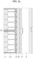
FIG. 2a is a cross-sectional view illustrating that a reverse flow prevention member and a bracket unit are coupled to a cell assembly unit. -
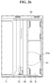
FIG. 2b illustrates that a reverse flow prevention member and a bracket unit are coupled to a cell assembly unit. -
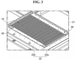
FIG. 3 is a perspective view of a battery pack according to an embodiment of the present disclosure. -
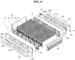
FIG. 4 is an exploded perspective view of a battery pack according to an embodiment of the present disclosure. - Reference will now be made in detail to embodiments of the disclosure, examples of which are illustrated in the accompanying drawings. Wherever possible, the same reference numbers will be used throughout the drawings to refer to the same or like parts. In general, a suffix such as "module" and "unit" may be used to refer to elements or components. Use of such a suffix herein is merely intended to facilitate description of the present disclosure, and the suffix itself is not intended to give any special meaning or function. It will be noted that a detailed description of known arts will be omitted if it is determined that the detailed description of the known arts can obscure the embodiments of the disclosure. The accompanying drawings are used to help easily understand various technical features and it should be understood that embodiments presented herein are not limited by the accompanying drawings. As such, the present disclosure should be construed to extend to any alterations, equivalents and substitutes in addition to those which are particularly set out in the accompanying drawings.
- The terms including an ordinal number such as first, second, etc. may be used to describe various components, but the components are not limited by such terms. The terms are used only for the purpose of distinguishing one component from other components.
- When any component is described as "being connected" or "being coupled" to other component, this should be understood to mean that another component may exist between them, although any component may be directly connected or coupled to the other component. In contrast, when any component is described as "being directly connected" or "being directly coupled" to other component, this should be understood to mean that no component exists between them.
- A singular expression can include a plural expression as long as it does not have an apparently different meaning in context.
- In the present disclosure, terms "include" and "have" should be understood to be intended to designate that illustrated features, numbers, steps, operations, components, parts or combinations thereof are present and not to preclude the existence of one or more different features, numbers, steps, operations, components, parts or combinations thereof, or the possibility of the addition thereof.
- In the drawings, sizes of the components may be exaggerated or reduced for convenience of explanation. For example, the size and the thickness of each component illustrated in the drawings are arbitrarily illustrated for convenience of explanation, and thus the present disclosure is not limited thereto unless specified as such.
- If any embodiment is implementable differently, a specific order of processes may be performed differently from the order described. For example, two consecutively described processes may be performed substantially at the same time, or performed in the order opposite to the described order.
- In the following embodiments, when layers, areas, components, etc. are connected, the following embodiments include both the case where layers, areas, and components are directly connected, and the case where layers, areas, and components are indirectly connected to other layers, areas, and components intervening between them. For example, when layers, areas, components, etc. are electrically connected, the present disclosure includes both the case where layers, areas, and components are directly electrically connected, and the case where layers, areas, and components are indirectly electrically connected to other layers, areas, and components intervening between them.
- The present disclosure relates to a battery pack and can secure a flow path capable of smoothly discharging a flame or a high-temperature gas generated by an explosion of a battery cell, in a battery pack, in which battery cells are directly installed, in a vehicle or the like.
- In another aspect, a battery pack according to the present disclosure can present configuration capable of preventing heat propagation by preventing a gas discharged in any one battery cell from being introduced into another battery cell in a thermal runaway situation.
- Referring to
FIGS. 1 to 4 , abattery pack 1 according to an embodiment of the present disclosure may include acell assembly unit 10, aframe unit 20, and abracket unit 30. - The
cell assembly unit 10 may include a plurality ofbattery cells 11 that are arranged to be stacked in one direction. Theframe unit 20 may accommodate thecell assembly unit 10. - The
bracket unit 30 may be coupled to theframe unit 20. Thebracket unit 30 may fix thecell assembly unit 10 to theframe unit 20. Thebracket unit 30 may form a flow path B together with theframe unit 20. - When a flame or a gas is generated in any one of the plurality of
battery cells 11, the flow path B may be a path for discharging the flame or the gas. For example, the flow path B may be a passage or a path through which gas flows. - The
battery pack 1 according to an embodiment of the present disclosure may include a reverseflow prevention member 40. The reverseflow prevention member 40 may selectively discharge the flame or the gas to the flow path B. - For example, the
bracket unit 30 may be coupled to thecell assembly unit 10 and may couple thecell assembly unit 10 to theframe unit 20. Thebracket unit 30 may prevent thecell assembly unit 10 from being detached. For example, thecell assembly unit 10 may not be detached from theframe unit 20 by catching on thebracket unit 30. - That is, the
bracket unit 30 can simultaneously perform a function of forming the flow path B and a function of fixing thecell assembly unit 10. Therefore, an existing problem of a reduction in an energy density caused by separately providing the configuration for forming the flow path B and the configuration for fixing thebattery cells 11 can be solved through thebracket unit 30 according to an embodiment of the present disclosure. Hence, the present disclosure has an advantage in that the energy density can be increased by installing a relatively large number ofbattery cells 11. - The
cell assembly unit 10 may include the plurality ofbattery cells 11. Thecell assembly unit 10 may include abus bar 12 and aside cover 13 that electrically connect the plurality ofbattery cells 11 to each other. - The
battery cell 11 may include an electrode assembly and an exterior material surrounding the electrode assembly. - The electrode assembly may substantially contain an electrolyte and may be accommodated in the exterior material together with the electrolyte. The electrolyte may include an organic solvent such as ethylene carbonate (EC), propylene carbonate (PC), diethyl carbonate (DEC), ethyl methyl carbonate (EMC), and dimethyl carbonate (DMC), and a lithium salt such as LiPF6 and LiBF4. The electrolyte may be a liquid, solid or gel phase.
- The exterior material may protect the electrode assembly and accommodate the electrolyte. For example, the exterior material may be a pouch-shaped member or a can-shaped member. A pouch-shaped battery cell, a can-shaped battery cell, etc. are merely an example of the
battery cell 11 accommodated in thebattery pack 1 according to the present disclosure. Thebattery cell 11 accommodated in thebattery pack 1 according to the present disclosure is not limited to the battery cells described above. - The
frame unit 20 may accommodate thecell assembly unit 10. Theframe unit 20 airtightly accommodates the periphery of thecell assembly unit 10, and thus can prevent a flame or gas generated by the explosion of any one of thebattery cells 11 included in thecell assembly unit 10 from being discharged to the outside. In this case, the flame or the gas may be guided to the flow path B formed by theframe unit 20 and thebracket unit 30 and may be discharged to the outside. - For example, the
frame unit 20 may accommodate a plurality ofcell assembly units 10, and may provide a plurality of compartments in which the respectivecell assembly units 10 are sealed. To this end, theframe unit 20 according to an embodiment of the present invention may include alower frame 21, aside frame 22, and anupper frame 23. - The
cell assembly unit 10 may be placed on thelower frame 21. Thelower frame 21 may face a lower part of thecell assembly unit 10. A lower end of theside frame 22 may be coupled to thelower frame 21. Theside frame 22 may surround the side of thecell assembly unit 10 in a perimeter direction. Theside frame 22 and thebracket unit 30 may form the flow path B. Theside frame 22 may correspond to a side surface of thecell assembly unit 10. Theupper frame 23 may be coupled to an upper end of theside frame 22. Theupper frame 23 may cover thecell assembly unit 10. Theupper frame 23 may face an upper part of thecell assembly unit 10. - The
cell assembly unit 10 may be placed on thelower frame 21. An area of thelower frame 21 may be divided by theside frame 22 so that the plurality ofcell assembly units 10 can be isolated from each other. Thelower frame 21 is one frame on which all the plurality ofcell assembly units 10 are placed. Theside frame 22 may divide thelower frame 21 into a plurality of areas (compartments), each of which accommodates eachcell assembly unit 10. - For example, the
lower frame 21 may be a frame included in a floor portion below a boarding area of a vehicle frame. In order to improve a heat dissipation performance, a heat conducting member may be interposed between thecell assembly unit 10 and thelower frame 21. For example, the heat conducting member may be applied between thecell assembly unit 10 and thelower frame 21. - The
side frame 22 may surround the periphery of thecell assembly unit 10. To this end, the lower end of theside frame 22 may be coupled to an upper surface of thelower frame 21. Theside frame 22 may divide thelower frame 21 into a plurality of areas. For example, theside frame 22 may be disposed to form compartments corresponding to a plurality of rectangular areas on the upper surface of thelower frame 21. - The
side frame 22 according to an embodiment of the present disclosure may include afirst side frame 22a and asecond side frame 22b. - The
first side frame 22a may be disposed on one side of thecell assembly unit 10. Thesecond side frame 22b may be disposed on another side of thecell assembly unit 10. - The
bracket unit 30 may be disposed between thesecond side frame 22b and thecell assembly unit 10. Thebracket unit 30 and thesecond side frame 22b may form the flow path B. That is, thesecond side frame 22b may form a part of the flow path B, and thebracket unit 30 may form a remaining part of the flow path B. - The
upper frame 23 may cover upper parts of a predetermined number ofbattery cells 11 on a per number basis. Thus, a space inside the compartment formed by theframe unit 20 can be sealed. To this end, theupper frame 23 may be coupled to the upper end of theside frame 22 and an upper end of thebracket unit 30. - At least one thermal
diffusion prevention member 50 may be disposed between the plurality ofbattery cells 11. The thermaldiffusion prevention member 50 is disposed between thebattery cells 11 that are adjacent to each other, and thus can block heat from being diffused between thebattery cells 11 that are adjacent to each other. - The
bracket unit 30 according to an embodiment of the present disclosure may include asupport plate portion 31 that faces the side of thecell assembly unit 10 and is disposed in parallel to thebus bar 12, anupper flange portion 32 positioned at an upper end of thesupport plate portion 31, and alower flange portion 33 positioned at a lower end of thesupport plate portion 31. - For example, the
upper flange portion 32 may extend from an upper end of thesupport plate portion 31 toward thesecond side frame 22b, or may extend toward thesecond side frame 22b and thecell assembly unit 10 in both directions. Theupper flange portion 32 may be fastened to thesecond side frame 22b. Hence, thecell assembly unit 10 may be fixed to theframe unit 20. - The
upper flange portion 32 may be coupled to theupper frame 23. For example, theupper flange portion 32, thesecond side frame 22b, and theupper frame 23 may be coupled through one bolt. Hence, the present disclosure can reduce the coupling process time by reducing the number of bolt coupling operations. - The
lower flange portion 33 may extend from the lower end of thesupport plate portion 31 toward thesecond side frame 22b. Thelower flange portion 33 may allow thesupport plate portion 31 to be placed and supported on thelower frame 21. - The
support plate portion 31 may have a throughhole 31a that communicates between a space, in which thecell assembly unit 10 is disposed, and the flow path B. A plurality of throughholes 31a may be provided. The plurality of throughholes 31a may be arranged along a longitudinal direction of thesupport plate portion 31. A shape of the throughhole 31a may include a quadrangle, a circle, or other polygonal shapes. The throughhole 31a may be positioned or formed between the reverseflow prevention member 40 and the flow path B. - The through
hole 31a is formed in thesupport plate portion 31, and thus the flame or gas generated in any onebattery cell 11 may be discharged to the flow path B. That is, the flame or the gas may pass through the throughhole 31a and may be introduced into the flow path B. - For example, the
bracket unit 30 may have heat resistance and/or fire resistance characteristics. For example, thebracket unit 30 may be formed of a material, such as a metal, a resin, a composite material, and a fiber-reinforced composite material, having rigidity of about 0.5 GPa or more. Accordingly, thebracket unit 30 can secure rigidity for fixing thecell assembly unit 10 to theframe unit 20 while forming the flow path B. In addition, thebracket unit 30 may be manufactured by going through post-processing such as coating and/or heat treatment in order to reinforce heat resistance and/or fire resistance and/or rigidity. - A shape of the reverse
flow prevention member 40 according to an embodiment of the present disclosure may have a pad shape. The reverseflow prevention member 40 may be made of a heat resistant material with air permeability. The reverseflow prevention member 40 may extend in parallel to thesupport plate portion 31 of thebracket unit 30 along thebus bar 12 of thecell assembly unit 10. For example, the reverseflow prevention member 40 may be disposed between thebus bar 12 and thebracket unit 30. Accordingly, the reverseflow prevention member 40 may selectively pass through the flame or the gas so that the flame or the gas flows in one direction. - For example, since a plurality of "gas permeation holes" are formed in the reverse
flow prevention member 40, the reverseflow prevention member 40 may have air permeability (or gas permeability). The gas permeation hole of the reverseflow prevention member 40 may extend from one end and lead to the other end. For example, one end of the gas permeation hole may be opened facing thebus bar 12. For example, the other end of the gas permeation hole may be opened toward the flow path B. For example, the other end of the gas transmission hole may face the throughhole 31a and communicate with the throughhole 31a. - A cross-sectional size of each of the plurality of gas permeation holes (not shown) of the reverse
flow prevention member 40 may be smaller than the size of the flow path B. Here, a cross section of each of the plurality of gas permeation holes (not shown) may mean a cross section obtained by cutting the gas permeation hole (not shown) perpendicular to a longitudinal direction of the gas permeation hole (not shown). The longitudinal direction of the gas permeation hole (not shown) may be a direction from one end of the gas permeation hole (not shown) toward the other end. - That is, when thermal runaway due to explosion occurs in any one of the plurality of
battery cells 11, a gas generated inside thebattery cells 11 may pass through a small space between the bus bars 12 and may be rapidly discharged. Therefore, a flow rate of the gas can increase, and thus the gas can pass through the reverseflow prevention member 40 with a strong pressure. - The gas that has passed through the reverse
flow prevention member 40 may pass through the throughhole 31a of thebracket unit 30 and may be introduced into the flow path B, which is a wide space. A density and a velocity of the gas in the flow path B may be less than a density and a velocity of the gas in the reverseflow prevention member 40, respectively. That is, a pressure (atmospheric pressure) in the flow path B may be less than a pressure (higher than atmospheric pressure) in the reverseflow prevention member 40. - Accordingly, it may be difficult for the gas positioned in the flow path B to pass through the reverse
flow prevention member 40 and enter thebattery cell 11. That is, the gas in the flow path B does not pass through the reverseflow prevention member 40 and enter thebattery cell 11, and can be discharged to the outside along the flow path B. - In other words, the reverse
flow prevention member 40 can allow the gas to be introduced from thecell assembly unit 10 to the flow path B and can block the gas from reversely flowing from the flow path B into thecell assembly unit 10. - As described above, the
battery pack 1 according to the present disclosure includes the reverseflow prevention member 40, and thus can selectively pass through the gas so that the gas flows in only one direction. Hence, when thermal runaway occurs in any one compartment, thebattery pack 1 according to the present disclosure can prevent heat from being propagated to other compartments after only thebattery cells 11 in the corresponding compartment are burned out. - The
cell assembly unit 10 may include thebus bar 12 to which electrode leads 11a of the plurality ofbattery cells 11 are coupled, an insulatingcover 14 covering thebus bar 12, theside cover 13 covering outermost side portions of the plurality ofbattery cells 11, and the reverseflow prevention member 40 coupled to thebus bar 12 or the insulatingcover 14. - The
bus bar 12 may be coupled to the plurality ofbattery cells 11. Thebus bar 12 may support all the plurality ofbattery cells 11. To this end, thebus bar 12 may include a plurality of coupling holes (not shown) coupled to the electrode leads 11a of thebattery cells 11. - The
bus bar 12 may be connected to an electrode strip (not shown). Thebus bar 12 may transfer electrical energy generated in the plurality ofbattery cells 11 to the electrode strip (not shown), and the electrode strip may supply the electrical energy to an external device (not shown) such as an electric vehicle. For example, the external device is not limited to the electric vehicle and may include a power tool, an electric bicycle, urban air mobility (UAM), an energy storage system (ESS), and the like. - The insulating
cover 14 may cover and protect thebus bar 12. For example, the insulatingcover 14 may insulate between thebus bar 12 and an external metal structure. The insulatingcover 14 may be disposed between the reverseflow prevention member 40 and thesupport plate portion 31. - The reverse
flow prevention member 40 may be disposed between thebus bar 12 and the insulatingcover 14. The reverseflow prevention member 40 may extend along thebus bar 12 or the insulatingcover 14. The reverseflow prevention member 40 may be formed to discharge the flame or gas generated in thebattery cell 11 to the flow path B. To this end, the reverseflow prevention member 40 may be made of a flame retardant material. - The reverse
flow prevention member 40 may allow the gas generated in one of the plurality ofbattery cells 11 to be discharged to the outside of the insulatingcover 14 and may block the gas positioned outside the insulatingcover 14 from being introduced into the plurality ofbattery cells 11. - In order to discharge the gas generated in the
battery cell 11 to the flow path B, the insulatingcover 14 may have anopen hole 14a corresponding to the throughhole 31a. A position on theopen hole 14a may correspond to a position where the throughhole 31a is formed. - A plurality of opening
holes 14a may be provided. The plurality ofopen holes 14a may be arranged along a longitudinal direction of the insulatingcover 14. The number ofopen holes 14a may correspond to the number of throughholes 31a. - The side cover 13 may be provided to pack the plurality of
battery cells 11 in association with the insulatingcover 14 and thebracket unit 30. For example, theside cover 13 may cover the outermost side portions of the stacked plurality ofbattery cells 11 to protect thebattery cells 11. - Some embodiments or other embodiments of the present disclosure described above are not mutually exclusive or distinct from each other. Configurations or functions of some embodiments or other embodiments of the present disclosure described above can be used together or combined with each other.
- It is apparent to those skilled in the art that the present disclosure can be embodied in other specific forms without departing from the spirit and essential features of the present disclosure. Accordingly, the above detailed description should not be construed as limiting in all aspects and should be considered as illustrative. The scope of the present disclosure should be determined by rational interpretation of the appended claims, and all modifications within an equivalent scope of the present disclosure are included in the scope of the present disclosure.
Claims (15)
- A battery pack comprising:a cell assembly unit including a plurality of battery cells and a bus bar configured to electrically connect the plurality of battery cells;a frame unit accommodating the cell assembly unit;a bracket unit fixing the cell assembly unit to the frame unit, wherein the bracket unit and the frame unit form a flow path through which a gas is discharged; anda reverse flow prevention member disposed between the bus bar and the bracket unit, the reverse flow prevention member including a plurality of gas permeation holes, each of which extends from one end facing the bus bar and leads to another end facing the flow path.
- The battery pack of claim 1, wherein the reverse flow prevention member extends along the bus bar and is made of a heat resistant material.
- The battery pack of claim 1 or 2, wherein when a thermal runaway occurs in at least one of the plurality of battery cells to generate the gas, a pressure inside the reverse flow prevention member is greater than a pressure inside the flow path.
- The battery pack of any one of claims 1 to 3, wherein the bracket unit includes a through hole positioned between the reverse flow prevention member and the flow path.
- The battery pack of claim 4, wherein the bracket unit includes:a support plate portion disposed in parallel to the bus bar;an upper flange portion disposed at an upper end of the support plate portion; anda lower flange portion disposed at a lower end of the support plate portion,wherein the through hole is formed to pass through the support plate portion.
- The battery pack of claim 5, wherein the through hole includes a plurality of through holes, and
wherein the plurality of through holes are arranged along a longitudinal direction of the support plate portion. - The battery pack of claim 5 or 6, further comprising an insulating cover between the reverse flow prevention member and the support plate portion,
wherein the insulating cover includes an open hole corresponding to the through hole. - The battery pack of claim 7, wherein the open hole includes a plurality of open holes, and
wherein the plurality of open holes are arranged along a longitudinal direction of the insulating cover. - The battery pack of any one of claims 1 to 8, wherein the frame unit includes:a lower frame on which the cell assembly unit is placed;a side frame corresponding to a side of the cell assembly unit, wherein the side frame and the bracket unit form the flow path; andan upper frame configured to cover the cell assembly unit.
- The battery pack of claim 9, wherein a heat conducting member is applied between the cell assembly unit and the lower frame.
- The battery pack of any one of claims 1 to 10, further comprising at least one thermal diffusion prevention member placed between the plurality of battery cells.
- A cell assembly unit comprising:a plurality of battery cells each including an electrode tab and arranged along one direction;a bus bar disposed at one side of the plurality of battery cells and electrically connected to the electrode tabs;an insulating cover disposed at one side of the bus bar and configured to insulate the bus bar; anda reverse flow prevention member coupled to one of the bus bar and the insulating cover,wherein the reverse flow prevention member allows a gas generated in at least one of the plurality of battery cells to be discharged to an outside of the insulating cover and blocks the gas from being introduced from the outside of the insulating cover to the plurality of battery cells.
- The cell assembly unit of claim 12, further comprising at least one thermal diffusion prevention member placed between the plurality of battery cells.
- The cell assembly unit of claim 12 or 13, wherein the reverse flow prevention member extends along the bus bar or the insulating cover and is made of a heat resistant material.
- The cell assembly unit of any one of claims 12 to 14, wherein the insulating cover includes an open hole.
Applications Claiming Priority (1)
| Application Number | Priority Date | Filing Date | Title |
|---|---|---|---|
| KR1020210115127A KR102915661B1 (en) | 2021-08-30 | 2021-08-30 | Cell assembly unit and battery pack having the same |
Publications (2)
| Publication Number | Publication Date |
|---|---|
| EP4142017A1 true EP4142017A1 (en) | 2023-03-01 |
| EP4142017B1 EP4142017B1 (en) | 2025-04-02 |
Family
ID=83151412
Family Applications (1)
| Application Number | Title | Priority Date | Filing Date |
|---|---|---|---|
| EP22192726.2A Active EP4142017B1 (en) | 2021-08-30 | 2022-08-30 | Cell assembly unit and battery pack including the same |
Country Status (4)
| Country | Link |
|---|---|
| US (1) | US12476325B2 (en) |
| EP (1) | EP4142017B1 (en) |
| KR (1) | KR102915661B1 (en) |
| CN (1) | CN115732826A (en) |
Cited By (1)
| Publication number | Priority date | Publication date | Assignee | Title |
|---|---|---|---|---|
| EP4579920A4 (en) * | 2023-03-02 | 2026-03-11 | Lg Energy Solution Ltd | BATTERY MODULE WITH FLAME EMISSION BLOCKING UNIT AND BATTERY PACK SO THAT |
Families Citing this family (2)
| Publication number | Priority date | Publication date | Assignee | Title |
|---|---|---|---|---|
| KR20240163853A (en) * | 2023-05-11 | 2024-11-19 | 주식회사 엘지에너지솔루션 | Battery module, battery pack, and energy storage system |
| WO2025155006A1 (en) * | 2024-01-19 | 2025-07-24 | 주식회사 엘지에너지솔루션 | Battery module, and battery pack and vehicle including same |
Citations (7)
| Publication number | Priority date | Publication date | Assignee | Title |
|---|---|---|---|---|
| WO2006112266A1 (en) * | 2005-04-13 | 2006-10-26 | Matsushita Electric Industrial Co., Ltd. | Large-sized power supply device |
| US20190097192A1 (en) * | 2017-09-27 | 2019-03-28 | Lg Chem, Ltd. | Battery module, and battery pack and vehicle including the same |
| KR102061872B1 (en) | 2016-01-28 | 2020-01-02 | 주식회사 엘지화학 | Case for Secondary Battery Pack and Secondary Battery Pack including the same |
| CN211404602U (en) * | 2020-03-27 | 2020-09-01 | 中航锂电(洛阳)有限公司 | Laminate polymer battery module |
| WO2020246721A1 (en) * | 2019-06-05 | 2020-12-10 | 주식회사 엘지화학 | Battery rack and power storage device comprising same |
| KR20210004189A (en) * | 2019-07-03 | 2021-01-13 | 주식회사 엘지화학 | Battery Module Including Flame Retardant Plate, Battery Rack and Power Storage Device Including the Same |
| KR20210115127A (en) | 2020-03-12 | 2021-09-27 | 송병준 | Multi-stage tray device for box packing machine |
Family Cites Families (3)
| Publication number | Priority date | Publication date | Assignee | Title |
|---|---|---|---|---|
| JP4246600B2 (en) | 2002-10-28 | 2009-04-02 | 古河電池株式会社 | Battery exhaust structure |
| JP2015118811A (en) | 2013-12-18 | 2015-06-25 | 日産自動車株式会社 | Secondary battery |
| CN108496261B (en) * | 2016-01-15 | 2021-03-16 | 株式会社村田制作所 | Battery |
-
2021
- 2021-08-30 KR KR1020210115127A patent/KR102915661B1/en active Active
-
2022
- 2022-08-29 US US17/897,277 patent/US12476325B2/en active Active
- 2022-08-29 CN CN202211041922.8A patent/CN115732826A/en active Pending
- 2022-08-30 EP EP22192726.2A patent/EP4142017B1/en active Active
Patent Citations (7)
| Publication number | Priority date | Publication date | Assignee | Title |
|---|---|---|---|---|
| WO2006112266A1 (en) * | 2005-04-13 | 2006-10-26 | Matsushita Electric Industrial Co., Ltd. | Large-sized power supply device |
| KR102061872B1 (en) | 2016-01-28 | 2020-01-02 | 주식회사 엘지화학 | Case for Secondary Battery Pack and Secondary Battery Pack including the same |
| US20190097192A1 (en) * | 2017-09-27 | 2019-03-28 | Lg Chem, Ltd. | Battery module, and battery pack and vehicle including the same |
| WO2020246721A1 (en) * | 2019-06-05 | 2020-12-10 | 주식회사 엘지화학 | Battery rack and power storage device comprising same |
| KR20210004189A (en) * | 2019-07-03 | 2021-01-13 | 주식회사 엘지화학 | Battery Module Including Flame Retardant Plate, Battery Rack and Power Storage Device Including the Same |
| KR20210115127A (en) | 2020-03-12 | 2021-09-27 | 송병준 | Multi-stage tray device for box packing machine |
| CN211404602U (en) * | 2020-03-27 | 2020-09-01 | 中航锂电(洛阳)有限公司 | Laminate polymer battery module |
Cited By (1)
| Publication number | Priority date | Publication date | Assignee | Title |
|---|---|---|---|---|
| EP4579920A4 (en) * | 2023-03-02 | 2026-03-11 | Lg Energy Solution Ltd | BATTERY MODULE WITH FLAME EMISSION BLOCKING UNIT AND BATTERY PACK SO THAT |
Also Published As
| Publication number | Publication date |
|---|---|
| KR102915661B1 (en) | 2026-01-20 |
| KR20230032363A (en) | 2023-03-07 |
| CN115732826A (en) | 2023-03-03 |
| US12476325B2 (en) | 2025-11-18 |
| EP4142017B1 (en) | 2025-04-02 |
| US20230067336A1 (en) | 2023-03-02 |
Similar Documents
| Publication | Publication Date | Title |
|---|---|---|
| EP4142017A1 (en) | Cell assembly unit and battery pack including the same | |
| EP3809487B1 (en) | Protection plate, battery cell assembly, battery module and vehicle | |
| US12068495B2 (en) | Battery module | |
| KR102834722B1 (en) | Battery module with improved gas venting structure and battery pack including the same | |
| CN113966565A (en) | Battery pack and transportation equipment | |
| EP4007052A1 (en) | Battery sub-packing unit | |
| KR20170044473A (en) | Battery Pack | |
| JP2006185894A (en) | Film exterior electrical device assembly | |
| JP7483028B2 (en) | Battery pack and device including same | |
| KR20220120001A (en) | Battery module and battery pack including the same | |
| CN113497300B (en) | Battery Module | |
| US20250329852A1 (en) | Battery Pack | |
| JP7701115B2 (en) | Battery pack and device including same | |
| KR102912504B1 (en) | Battery pack and vehicle comprising the same | |
| EP4024573A1 (en) | Battery pack having heat diffusion preventing structure applied between battery modules | |
| JP7693011B2 (en) | Battery pack and automobile including same | |
| EP4468466A1 (en) | Battery module with reinforced safety | |
| KR102811031B1 (en) | Battery assembly with reinforeced safety | |
| KR20240070987A (en) | Battery pack | |
| CN115943523A (en) | Battery module and battery pack including the battery module | |
| WO2023070399A1 (en) | Battery, electric device, and method for manufacturing battery | |
| KR102847205B1 (en) | Battery module, Battery pack and vehicle including the same | |
| US20260038950A1 (en) | Battery Pack and Vehicle Including Same | |
| KR102954658B1 (en) | Battery module | |
| KR20250143175A (en) | Battery module and battery pack having it |
Legal Events
| Date | Code | Title | Description |
|---|---|---|---|
| PUAI | Public reference made under article 153(3) epc to a published international application that has entered the european phase |
Free format text: ORIGINAL CODE: 0009012 |
|
| STAA | Information on the status of an ep patent application or granted ep patent |
Free format text: STATUS: REQUEST FOR EXAMINATION WAS MADE |
|
| 17P | Request for examination filed |
Effective date: 20220920 |
|
| AK | Designated contracting states |
Kind code of ref document: A1 Designated state(s): AL AT BE BG CH CY CZ DE DK EE ES FI FR GB GR HR HU IE IS IT LI LT LU LV MC MK MT NL NO PL PT RO RS SE SI SK SM TR |
|
| P01 | Opt-out of the competence of the unified patent court (upc) registered |
Effective date: 20230602 |
|
| STAA | Information on the status of an ep patent application or granted ep patent |
Free format text: STATUS: EXAMINATION IS IN PROGRESS |
|
| 17Q | First examination report despatched |
Effective date: 20240405 |
|
| GRAP | Despatch of communication of intention to grant a patent |
Free format text: ORIGINAL CODE: EPIDOSNIGR1 |
|
| STAA | Information on the status of an ep patent application or granted ep patent |
Free format text: STATUS: GRANT OF PATENT IS INTENDED |
|
| INTG | Intention to grant announced |
Effective date: 20241112 |
|
| GRAS | Grant fee paid |
Free format text: ORIGINAL CODE: EPIDOSNIGR3 |
|
| GRAA | (expected) grant |
Free format text: ORIGINAL CODE: 0009210 |
|
| STAA | Information on the status of an ep patent application or granted ep patent |
Free format text: STATUS: THE PATENT HAS BEEN GRANTED |
|
| AK | Designated contracting states |
Kind code of ref document: B1 Designated state(s): AL AT BE BG CH CY CZ DE DK EE ES FI FR GB GR HR HU IE IS IT LI LT LU LV MC MK MT NL NO PL PT RO RS SE SI SK SM TR |
|
| REG | Reference to a national code |
Ref country code: GB Ref legal event code: FG4D |
|
| REG | Reference to a national code |
Ref country code: CH Ref legal event code: EP |
|
| REG | Reference to a national code |
Ref country code: IE Ref legal event code: FG4D |
|
| REG | Reference to a national code |
Ref country code: DE Ref legal event code: R096 Ref document number: 602022012496 Country of ref document: DE |
|
| PGFP | Annual fee paid to national office [announced via postgrant information from national office to epo] |
Ref country code: FR Payment date: 20250624 Year of fee payment: 4 |
|
| REG | Reference to a national code |
Ref country code: NL Ref legal event code: MP Effective date: 20250402 |
|
| PG25 | Lapsed in a contracting state [announced via postgrant information from national office to epo] |
Ref country code: NL Free format text: LAPSE BECAUSE OF FAILURE TO SUBMIT A TRANSLATION OF THE DESCRIPTION OR TO PAY THE FEE WITHIN THE PRESCRIBED TIME-LIMIT Effective date: 20250402 |
|
| REG | Reference to a national code |
Ref country code: AT Ref legal event code: MK05 Ref document number: 1782231 Country of ref document: AT Kind code of ref document: T Effective date: 20250402 |
|
| PG25 | Lapsed in a contracting state [announced via postgrant information from national office to epo] |
Ref country code: ES Free format text: LAPSE BECAUSE OF FAILURE TO SUBMIT A TRANSLATION OF THE DESCRIPTION OR TO PAY THE FEE WITHIN THE PRESCRIBED TIME-LIMIT Effective date: 20250402 Ref country code: FI Free format text: LAPSE BECAUSE OF FAILURE TO SUBMIT A TRANSLATION OF THE DESCRIPTION OR TO PAY THE FEE WITHIN THE PRESCRIBED TIME-LIMIT Effective date: 20250402 Ref country code: PT Free format text: LAPSE BECAUSE OF FAILURE TO SUBMIT A TRANSLATION OF THE DESCRIPTION OR TO PAY THE FEE WITHIN THE PRESCRIBED TIME-LIMIT Effective date: 20250804 |
|
| PGFP | Annual fee paid to national office [announced via postgrant information from national office to epo] |
Ref country code: DE Payment date: 20250624 Year of fee payment: 4 |
|
| REG | Reference to a national code |
Ref country code: LT Ref legal event code: MG9D |
|
| PG25 | Lapsed in a contracting state [announced via postgrant information from national office to epo] |
Ref country code: GR Free format text: LAPSE BECAUSE OF FAILURE TO SUBMIT A TRANSLATION OF THE DESCRIPTION OR TO PAY THE FEE WITHIN THE PRESCRIBED TIME-LIMIT Effective date: 20250703 Ref country code: NO Free format text: LAPSE BECAUSE OF FAILURE TO SUBMIT A TRANSLATION OF THE DESCRIPTION OR TO PAY THE FEE WITHIN THE PRESCRIBED TIME-LIMIT Effective date: 20250702 |
|
| PG25 | Lapsed in a contracting state [announced via postgrant information from national office to epo] |
Ref country code: PL Free format text: LAPSE BECAUSE OF FAILURE TO SUBMIT A TRANSLATION OF THE DESCRIPTION OR TO PAY THE FEE WITHIN THE PRESCRIBED TIME-LIMIT Effective date: 20250402 |
|
| PG25 | Lapsed in a contracting state [announced via postgrant information from national office to epo] |
Ref country code: BG Free format text: LAPSE BECAUSE OF FAILURE TO SUBMIT A TRANSLATION OF THE DESCRIPTION OR TO PAY THE FEE WITHIN THE PRESCRIBED TIME-LIMIT Effective date: 20250402 |
|
| PG25 | Lapsed in a contracting state [announced via postgrant information from national office to epo] |
Ref country code: HR Free format text: LAPSE BECAUSE OF FAILURE TO SUBMIT A TRANSLATION OF THE DESCRIPTION OR TO PAY THE FEE WITHIN THE PRESCRIBED TIME-LIMIT Effective date: 20250402 |
|
| PG25 | Lapsed in a contracting state [announced via postgrant information from national office to epo] |
Ref country code: AT Free format text: LAPSE BECAUSE OF FAILURE TO SUBMIT A TRANSLATION OF THE DESCRIPTION OR TO PAY THE FEE WITHIN THE PRESCRIBED TIME-LIMIT Effective date: 20250402 |
|
| PG25 | Lapsed in a contracting state [announced via postgrant information from national office to epo] |
Ref country code: RS Free format text: LAPSE BECAUSE OF FAILURE TO SUBMIT A TRANSLATION OF THE DESCRIPTION OR TO PAY THE FEE WITHIN THE PRESCRIBED TIME-LIMIT Effective date: 20250702 |
|
| PG25 | Lapsed in a contracting state [announced via postgrant information from national office to epo] |
Ref country code: IS Free format text: LAPSE BECAUSE OF FAILURE TO SUBMIT A TRANSLATION OF THE DESCRIPTION OR TO PAY THE FEE WITHIN THE PRESCRIBED TIME-LIMIT Effective date: 20250802 |
|
| PG25 | Lapsed in a contracting state [announced via postgrant information from national office to epo] |
Ref country code: LV Free format text: LAPSE BECAUSE OF FAILURE TO SUBMIT A TRANSLATION OF THE DESCRIPTION OR TO PAY THE FEE WITHIN THE PRESCRIBED TIME-LIMIT Effective date: 20250402 |
|
| REG | Reference to a national code |
Ref country code: DE Ref legal event code: R097 Ref document number: 602022012496 Country of ref document: DE |
|
| PG25 | Lapsed in a contracting state [announced via postgrant information from national office to epo] |
Ref country code: DK Free format text: LAPSE BECAUSE OF FAILURE TO SUBMIT A TRANSLATION OF THE DESCRIPTION OR TO PAY THE FEE WITHIN THE PRESCRIBED TIME-LIMIT Effective date: 20250402 Ref country code: SM Free format text: LAPSE BECAUSE OF FAILURE TO SUBMIT A TRANSLATION OF THE DESCRIPTION OR TO PAY THE FEE WITHIN THE PRESCRIBED TIME-LIMIT Effective date: 20250402 |
|
| PG25 | Lapsed in a contracting state [announced via postgrant information from national office to epo] |
Ref country code: CZ Free format text: LAPSE BECAUSE OF FAILURE TO SUBMIT A TRANSLATION OF THE DESCRIPTION OR TO PAY THE FEE WITHIN THE PRESCRIBED TIME-LIMIT Effective date: 20250402 |
|
| PG25 | Lapsed in a contracting state [announced via postgrant information from national office to epo] |
Ref country code: EE Free format text: LAPSE BECAUSE OF FAILURE TO SUBMIT A TRANSLATION OF THE DESCRIPTION OR TO PAY THE FEE WITHIN THE PRESCRIBED TIME-LIMIT Effective date: 20250402 |
|
| PG25 | Lapsed in a contracting state [announced via postgrant information from national office to epo] |
Ref country code: SK Free format text: LAPSE BECAUSE OF FAILURE TO SUBMIT A TRANSLATION OF THE DESCRIPTION OR TO PAY THE FEE WITHIN THE PRESCRIBED TIME-LIMIT Effective date: 20250402 |
|
| PG25 | Lapsed in a contracting state [announced via postgrant information from national office to epo] |
Ref country code: IT Free format text: LAPSE BECAUSE OF FAILURE TO SUBMIT A TRANSLATION OF THE DESCRIPTION OR TO PAY THE FEE WITHIN THE PRESCRIBED TIME-LIMIT Effective date: 20250402 |
|
| PLBE | No opposition filed within time limit |
Free format text: ORIGINAL CODE: 0009261 |
|
| STAA | Information on the status of an ep patent application or granted ep patent |
Free format text: STATUS: NO OPPOSITION FILED WITHIN TIME LIMIT |
|
| PG25 | Lapsed in a contracting state [announced via postgrant information from national office to epo] |
Ref country code: RO Free format text: LAPSE BECAUSE OF FAILURE TO SUBMIT A TRANSLATION OF THE DESCRIPTION OR TO PAY THE FEE WITHIN THE PRESCRIBED TIME-LIMIT Effective date: 20250402 |
|
| REG | Reference to a national code |
Ref country code: CH Ref legal event code: L10 Free format text: ST27 STATUS EVENT CODE: U-0-0-L10-L00 (AS PROVIDED BY THE NATIONAL OFFICE) Effective date: 20260211 |
|
| 26N | No opposition filed |
Effective date: 20260105 |
|
| REG | Reference to a national code |
Ref country code: CH Ref legal event code: H13 Free format text: ST27 STATUS EVENT CODE: U-0-0-H10-H13 (AS PROVIDED BY THE NATIONAL OFFICE) Effective date: 20260324 |
|
| PG25 | Lapsed in a contracting state [announced via postgrant information from national office to epo] |
Ref country code: MC Free format text: LAPSE BECAUSE OF FAILURE TO SUBMIT A TRANSLATION OF THE DESCRIPTION OR TO PAY THE FEE WITHIN THE PRESCRIBED TIME-LIMIT Effective date: 20250402 |
|
| PG25 | Lapsed in a contracting state [announced via postgrant information from national office to epo] |
Ref country code: LU Free format text: LAPSE BECAUSE OF NON-PAYMENT OF DUE FEES Effective date: 20250830 |
|
| PG25 | Lapsed in a contracting state [announced via postgrant information from national office to epo] |
Ref country code: CH Free format text: LAPSE BECAUSE OF NON-PAYMENT OF DUE FEES Effective date: 20250831 |