EP4141912A1 - Gate tie structures to buried or backside power rails - Google Patents
Gate tie structures to buried or backside power rails Download PDFInfo
- Publication number
- EP4141912A1 EP4141912A1 EP22182774.4A EP22182774A EP4141912A1 EP 4141912 A1 EP4141912 A1 EP 4141912A1 EP 22182774 A EP22182774 A EP 22182774A EP 4141912 A1 EP4141912 A1 EP 4141912A1
- Authority
- EP
- European Patent Office
- Prior art keywords
- conductive
- conductive material
- semiconductor
- dielectric
- layer
- Prior art date
- Legal status (The legal status is an assumption and is not a legal conclusion. Google has not performed a legal analysis and makes no representation as to the accuracy of the status listed.)
- Pending
Links
- 239000004065 semiconductor Substances 0.000 claims abstract description 183
- 239000000463 material Substances 0.000 claims abstract description 103
- 238000000034 method Methods 0.000 claims abstract description 97
- 239000004020 conductor Substances 0.000 claims abstract description 89
- 239000002074 nanoribbon Substances 0.000 claims abstract description 47
- 239000000758 substrate Substances 0.000 claims description 70
- 229910052710 silicon Inorganic materials 0.000 claims description 30
- 239000010703 silicon Substances 0.000 claims description 30
- WFKWXMTUELFFGS-UHFFFAOYSA-N tungsten Chemical compound [W] WFKWXMTUELFFGS-UHFFFAOYSA-N 0.000 claims description 19
- 229910052721 tungsten Inorganic materials 0.000 claims description 19
- 239000010937 tungsten Substances 0.000 claims description 19
- 229910052732 germanium Inorganic materials 0.000 claims description 11
- GNPVGFCGXDBREM-UHFFFAOYSA-N germanium atom Chemical compound [Ge] GNPVGFCGXDBREM-UHFFFAOYSA-N 0.000 claims description 11
- IJGRMHOSHXDMSA-UHFFFAOYSA-N Atomic nitrogen Chemical compound N#N IJGRMHOSHXDMSA-UHFFFAOYSA-N 0.000 claims description 8
- QVGXLLKOCUKJST-UHFFFAOYSA-N atomic oxygen Chemical compound [O] QVGXLLKOCUKJST-UHFFFAOYSA-N 0.000 claims description 6
- 229910052760 oxygen Inorganic materials 0.000 claims description 6
- 239000001301 oxygen Substances 0.000 claims description 6
- 229910052757 nitrogen Inorganic materials 0.000 claims description 4
- 229910052751 metal Inorganic materials 0.000 abstract description 43
- 239000002184 metal Substances 0.000 abstract description 43
- 239000003989 dielectric material Substances 0.000 abstract description 20
- 239000002070 nanowire Substances 0.000 abstract description 11
- 230000008569 process Effects 0.000 description 49
- XUIMIQQOPSSXEZ-UHFFFAOYSA-N Silicon Chemical compound [Si] XUIMIQQOPSSXEZ-UHFFFAOYSA-N 0.000 description 26
- VYPSYNLAJGMNEJ-UHFFFAOYSA-N Silicium dioxide Chemical compound O=[Si]=O VYPSYNLAJGMNEJ-UHFFFAOYSA-N 0.000 description 20
- 238000004891 communication Methods 0.000 description 16
- 230000006870 function Effects 0.000 description 15
- 238000001020 plasma etching Methods 0.000 description 15
- 238000005530 etching Methods 0.000 description 12
- 230000015572 biosynthetic process Effects 0.000 description 11
- 229910000577 Silicon-germanium Inorganic materials 0.000 description 10
- 239000000203 mixture Substances 0.000 description 8
- 235000012239 silicon dioxide Nutrition 0.000 description 8
- 239000000377 silicon dioxide Substances 0.000 description 8
- RTAQQCXQSZGOHL-UHFFFAOYSA-N Titanium Chemical compound [Ti] RTAQQCXQSZGOHL-UHFFFAOYSA-N 0.000 description 7
- 238000000151 deposition Methods 0.000 description 7
- 239000010936 titanium Substances 0.000 description 7
- 229910052719 titanium Inorganic materials 0.000 description 7
- OKTJSMMVPCPJKN-UHFFFAOYSA-N Carbon Chemical compound [C] OKTJSMMVPCPJKN-UHFFFAOYSA-N 0.000 description 6
- 229910052782 aluminium Inorganic materials 0.000 description 6
- XAGFODPZIPBFFR-UHFFFAOYSA-N aluminium Chemical compound [Al] XAGFODPZIPBFFR-UHFFFAOYSA-N 0.000 description 6
- 229910052799 carbon Inorganic materials 0.000 description 6
- 238000005229 chemical vapour deposition Methods 0.000 description 6
- 238000001459 lithography Methods 0.000 description 6
- 238000005498 polishing Methods 0.000 description 6
- 238000000231 atomic layer deposition Methods 0.000 description 5
- 238000001312 dry etching Methods 0.000 description 5
- 229910000449 hafnium oxide Inorganic materials 0.000 description 5
- WIHZLLGSGQNAGK-UHFFFAOYSA-N hafnium(4+);oxygen(2-) Chemical compound [O-2].[O-2].[Hf+4] WIHZLLGSGQNAGK-UHFFFAOYSA-N 0.000 description 5
- 230000000873 masking effect Effects 0.000 description 5
- 238000001039 wet etching Methods 0.000 description 5
- KJTLSVCANCCWHF-UHFFFAOYSA-N Ruthenium Chemical compound [Ru] KJTLSVCANCCWHF-UHFFFAOYSA-N 0.000 description 4
- 229910045601 alloy Inorganic materials 0.000 description 4
- 239000000956 alloy Substances 0.000 description 4
- 229910017052 cobalt Inorganic materials 0.000 description 4
- 239000010941 cobalt Substances 0.000 description 4
- GUTLYIVDDKVIGB-UHFFFAOYSA-N cobalt atom Chemical compound [Co] GUTLYIVDDKVIGB-UHFFFAOYSA-N 0.000 description 4
- 238000005516 engineering process Methods 0.000 description 4
- 238000000623 plasma-assisted chemical vapour deposition Methods 0.000 description 4
- 229910052707 ruthenium Inorganic materials 0.000 description 4
- 229910052814 silicon oxide Inorganic materials 0.000 description 4
- RYGMFSIKBFXOCR-UHFFFAOYSA-N Copper Chemical compound [Cu] RYGMFSIKBFXOCR-UHFFFAOYSA-N 0.000 description 3
- 229910000530 Gallium indium arsenide Inorganic materials 0.000 description 3
- ZOKXTWBITQBERF-UHFFFAOYSA-N Molybdenum Chemical compound [Mo] ZOKXTWBITQBERF-UHFFFAOYSA-N 0.000 description 3
- 229910052581 Si3N4 Inorganic materials 0.000 description 3
- BQCADISMDOOEFD-UHFFFAOYSA-N Silver Chemical compound [Ag] BQCADISMDOOEFD-UHFFFAOYSA-N 0.000 description 3
- NRTOMJZYCJJWKI-UHFFFAOYSA-N Titanium nitride Chemical compound [Ti]#N NRTOMJZYCJJWKI-UHFFFAOYSA-N 0.000 description 3
- KXNLCSXBJCPWGL-UHFFFAOYSA-N [Ga].[As].[In] Chemical compound [Ga].[As].[In] KXNLCSXBJCPWGL-UHFFFAOYSA-N 0.000 description 3
- LEVVHYCKPQWKOP-UHFFFAOYSA-N [Si].[Ge] Chemical compound [Si].[Ge] LEVVHYCKPQWKOP-UHFFFAOYSA-N 0.000 description 3
- 239000006117 anti-reflective coating Substances 0.000 description 3
- 229910052802 copper Inorganic materials 0.000 description 3
- 239000010949 copper Substances 0.000 description 3
- 230000008021 deposition Effects 0.000 description 3
- 239000002019 doping agent Substances 0.000 description 3
- 238000002955 isolation Methods 0.000 description 3
- 229910052750 molybdenum Inorganic materials 0.000 description 3
- 239000011733 molybdenum Substances 0.000 description 3
- 150000004767 nitrides Chemical class 0.000 description 3
- 229920002120 photoresistant polymer Polymers 0.000 description 3
- 238000005240 physical vapour deposition Methods 0.000 description 3
- 238000012545 processing Methods 0.000 description 3
- HQVNEWCFYHHQES-UHFFFAOYSA-N silicon nitride Chemical compound N12[Si]34N5[Si]62N3[Si]51N64 HQVNEWCFYHHQES-UHFFFAOYSA-N 0.000 description 3
- 229910052709 silver Inorganic materials 0.000 description 3
- 239000004332 silver Substances 0.000 description 3
- 229910000679 solder Inorganic materials 0.000 description 3
- 125000006850 spacer group Chemical group 0.000 description 3
- 239000000126 substance Substances 0.000 description 3
- 230000007704 transition Effects 0.000 description 3
- JBRZTFJDHDCESZ-UHFFFAOYSA-N AsGa Chemical compound [As]#[Ga] JBRZTFJDHDCESZ-UHFFFAOYSA-N 0.000 description 2
- 229910001218 Gallium arsenide Inorganic materials 0.000 description 2
- GPXJNWSHGFTCBW-UHFFFAOYSA-N Indium phosphide Chemical compound [In]#P GPXJNWSHGFTCBW-UHFFFAOYSA-N 0.000 description 2
- 238000007772 electroless plating Methods 0.000 description 2
- 238000009713 electroplating Methods 0.000 description 2
- 238000002149 energy-dispersive X-ray emission spectroscopy Methods 0.000 description 2
- 239000012212 insulator Substances 0.000 description 2
- MRELNEQAGSRDBK-UHFFFAOYSA-N lanthanum(3+);oxygen(2-) Chemical compound [O-2].[O-2].[O-2].[La+3].[La+3] MRELNEQAGSRDBK-UHFFFAOYSA-N 0.000 description 2
- 238000004519 manufacturing process Methods 0.000 description 2
- 230000007246 mechanism Effects 0.000 description 2
- 238000001465 metallisation Methods 0.000 description 2
- 238000012986 modification Methods 0.000 description 2
- 230000004048 modification Effects 0.000 description 2
- TWNQGVIAIRXVLR-UHFFFAOYSA-N oxo(oxoalumanyloxy)alumane Chemical compound O=[Al]O[Al]=O TWNQGVIAIRXVLR-UHFFFAOYSA-N 0.000 description 2
- 230000037361 pathway Effects 0.000 description 2
- 238000000988 reflection electron microscopy Methods 0.000 description 2
- 239000000523 sample Substances 0.000 description 2
- 238000001350 scanning transmission electron microscopy Methods 0.000 description 2
- 238000001004 secondary ion mass spectrometry Methods 0.000 description 2
- 150000004760 silicates Chemical class 0.000 description 2
- 238000003325 tomography Methods 0.000 description 2
- 239000004593 Epoxy Substances 0.000 description 1
- BPQQTUXANYXVAA-UHFFFAOYSA-N Orthosilicate Chemical compound [O-][Si]([O-])([O-])[O-] BPQQTUXANYXVAA-UHFFFAOYSA-N 0.000 description 1
- GWEVSGVZZGPLCZ-UHFFFAOYSA-N Titan oxide Chemical compound O=[Ti]=O GWEVSGVZZGPLCZ-UHFFFAOYSA-N 0.000 description 1
- 238000002441 X-ray diffraction Methods 0.000 description 1
- XWCMFHPRATWWFO-UHFFFAOYSA-N [O-2].[Ta+5].[Sc+3].[O-2].[O-2].[O-2] Chemical compound [O-2].[Ta+5].[Sc+3].[O-2].[O-2].[O-2] XWCMFHPRATWWFO-UHFFFAOYSA-N 0.000 description 1
- GNKTZDSRQHMHLZ-UHFFFAOYSA-N [Si].[Si].[Si].[Ti].[Ti].[Ti].[Ti].[Ti] Chemical compound [Si].[Si].[Si].[Ti].[Ti].[Ti].[Ti].[Ti] GNKTZDSRQHMHLZ-UHFFFAOYSA-N 0.000 description 1
- ILCYGSITMBHYNK-UHFFFAOYSA-N [Si]=O.[Hf] Chemical compound [Si]=O.[Hf] ILCYGSITMBHYNK-UHFFFAOYSA-N 0.000 description 1
- 238000004458 analytical method Methods 0.000 description 1
- 238000000137 annealing Methods 0.000 description 1
- VKJLWXGJGDEGSO-UHFFFAOYSA-N barium(2+);oxygen(2-);titanium(4+) Chemical compound [O-2].[O-2].[O-2].[Ti+4].[Ba+2] VKJLWXGJGDEGSO-UHFFFAOYSA-N 0.000 description 1
- 230000008901 benefit Effects 0.000 description 1
- 230000008878 coupling Effects 0.000 description 1
- 238000010168 coupling process Methods 0.000 description 1
- 238000005859 coupling reaction Methods 0.000 description 1
- 238000005137 deposition process Methods 0.000 description 1
- 230000009977 dual effect Effects 0.000 description 1
- 230000005670 electromagnetic radiation Effects 0.000 description 1
- 238000002003 electron diffraction Methods 0.000 description 1
- 238000001493 electron microscopy Methods 0.000 description 1
- 230000007613 environmental effect Effects 0.000 description 1
- 238000003384 imaging method Methods 0.000 description 1
- 229910052746 lanthanum Inorganic materials 0.000 description 1
- FZLIPJUXYLNCLC-UHFFFAOYSA-N lanthanum atom Chemical compound [La] FZLIPJUXYLNCLC-UHFFFAOYSA-N 0.000 description 1
- JQJCSZOEVBFDKO-UHFFFAOYSA-N lead zinc Chemical compound [Zn].[Pb] JQJCSZOEVBFDKO-UHFFFAOYSA-N 0.000 description 1
- 230000007774 longterm Effects 0.000 description 1
- 238000013507 mapping Methods 0.000 description 1
- 229910001092 metal group alloy Inorganic materials 0.000 description 1
- 229910044991 metal oxide Inorganic materials 0.000 description 1
- 150000004706 metal oxides Chemical class 0.000 description 1
- 150000002739 metals Chemical class 0.000 description 1
- BBTXSTYZFZSWQW-UHFFFAOYSA-N niobium(5+);pentasilicate Chemical compound [Nb+5].[Nb+5].[Nb+5].[Nb+5].[O-][Si]([O-])([O-])[O-].[O-][Si]([O-])([O-])[O-].[O-][Si]([O-])([O-])[O-].[O-][Si]([O-])([O-])[O-].[O-][Si]([O-])([O-])[O-] BBTXSTYZFZSWQW-UHFFFAOYSA-N 0.000 description 1
- KJXBRHIPHIVJCS-UHFFFAOYSA-N oxo(oxoalumanyloxy)lanthanum Chemical compound O=[Al]O[La]=O KJXBRHIPHIVJCS-UHFFFAOYSA-N 0.000 description 1
- SIWVEOZUMHYXCS-UHFFFAOYSA-N oxo(oxoyttriooxy)yttrium Chemical compound O=[Y]O[Y]=O SIWVEOZUMHYXCS-UHFFFAOYSA-N 0.000 description 1
- BPUBBGLMJRNUCC-UHFFFAOYSA-N oxygen(2-);tantalum(5+) Chemical compound [O-2].[O-2].[O-2].[O-2].[O-2].[Ta+5].[Ta+5] BPUBBGLMJRNUCC-UHFFFAOYSA-N 0.000 description 1
- RVTZCBVAJQQJTK-UHFFFAOYSA-N oxygen(2-);zirconium(4+) Chemical compound [O-2].[O-2].[Zr+4] RVTZCBVAJQQJTK-UHFFFAOYSA-N 0.000 description 1
- 238000007517 polishing process Methods 0.000 description 1
- 229910021420 polycrystalline silicon Inorganic materials 0.000 description 1
- 229920005591 polysilicon Polymers 0.000 description 1
- 238000004626 scanning electron microscopy Methods 0.000 description 1
- -1 silicon nitride) Chemical class 0.000 description 1
- 239000007787 solid Substances 0.000 description 1
- 238000003860 storage Methods 0.000 description 1
- VEALVRVVWBQVSL-UHFFFAOYSA-N strontium titanate Chemical compound [Sr+2].[O-][Ti]([O-])=O VEALVRVVWBQVSL-UHFFFAOYSA-N 0.000 description 1
- CZXRMHUWVGPWRM-UHFFFAOYSA-N strontium;barium(2+);oxygen(2-);titanium(4+) Chemical compound [O-2].[O-2].[O-2].[O-2].[Ti+4].[Sr+2].[Ba+2] CZXRMHUWVGPWRM-UHFFFAOYSA-N 0.000 description 1
- 229910001936 tantalum oxide Inorganic materials 0.000 description 1
- OGIDPMRJRNCKJF-UHFFFAOYSA-N titanium oxide Inorganic materials [Ti]=O OGIDPMRJRNCKJF-UHFFFAOYSA-N 0.000 description 1
- 238000012546 transfer Methods 0.000 description 1
- 229910052723 transition metal Inorganic materials 0.000 description 1
- 150000003624 transition metals Chemical class 0.000 description 1
- 238000004627 transmission electron microscopy Methods 0.000 description 1
- 238000002424 x-ray crystallography Methods 0.000 description 1
- 229910001928 zirconium oxide Inorganic materials 0.000 description 1
- GFQYVLUOOAAOGM-UHFFFAOYSA-N zirconium(iv) silicate Chemical compound [Zr+4].[O-][Si]([O-])([O-])[O-] GFQYVLUOOAAOGM-UHFFFAOYSA-N 0.000 description 1
Images


Classifications
-
- H—ELECTRICITY
- H01—ELECTRIC ELEMENTS
- H01L—SEMICONDUCTOR DEVICES NOT COVERED BY CLASS H10
- H01L23/00—Details of semiconductor or other solid state devices
- H01L23/52—Arrangements for conducting electric current within the device in operation from one component to another, i.e. interconnections, e.g. wires, lead frames
- H01L23/522—Arrangements for conducting electric current within the device in operation from one component to another, i.e. interconnections, e.g. wires, lead frames including external interconnections consisting of a multilayer structure of conductive and insulating layers inseparably formed on the semiconductor body
- H01L23/528—Geometry or layout of the interconnection structure
- H01L23/5286—Arrangements of power or ground buses
-
- H—ELECTRICITY
- H01—ELECTRIC ELEMENTS
- H01L—SEMICONDUCTOR DEVICES NOT COVERED BY CLASS H10
- H01L29/00—Semiconductor devices specially adapted for rectifying, amplifying, oscillating or switching and having potential barriers; Capacitors or resistors having potential barriers, e.g. a PN-junction depletion layer or carrier concentration layer; Details of semiconductor bodies or of electrodes thereof ; Multistep manufacturing processes therefor
- H01L29/40—Electrodes ; Multistep manufacturing processes therefor
- H01L29/401—Multistep manufacturing processes
-
- H—ELECTRICITY
- H01—ELECTRIC ELEMENTS
- H01L—SEMICONDUCTOR DEVICES NOT COVERED BY CLASS H10
- H01L21/00—Processes or apparatus adapted for the manufacture or treatment of semiconductor or solid state devices or of parts thereof
- H01L21/02—Manufacture or treatment of semiconductor devices or of parts thereof
- H01L21/02104—Forming layers
- H01L21/02365—Forming inorganic semiconducting materials on a substrate
- H01L21/02518—Deposited layers
- H01L21/02587—Structure
- H01L21/0259—Microstructure
-
- H—ELECTRICITY
- H01—ELECTRIC ELEMENTS
- H01L—SEMICONDUCTOR DEVICES NOT COVERED BY CLASS H10
- H01L21/00—Processes or apparatus adapted for the manufacture or treatment of semiconductor or solid state devices or of parts thereof
- H01L21/70—Manufacture or treatment of devices consisting of a plurality of solid state components formed in or on a common substrate or of parts thereof; Manufacture of integrated circuit devices or of parts thereof
- H01L21/71—Manufacture of specific parts of devices defined in group H01L21/70
- H01L21/768—Applying interconnections to be used for carrying current between separate components within a device comprising conductors and dielectrics
- H01L21/76838—Applying interconnections to be used for carrying current between separate components within a device comprising conductors and dielectrics characterised by the formation and the after-treatment of the conductors
- H01L21/76895—Local interconnects; Local pads, as exemplified by patent document EP0896365
-
- H—ELECTRICITY
- H01—ELECTRIC ELEMENTS
- H01L—SEMICONDUCTOR DEVICES NOT COVERED BY CLASS H10
- H01L21/00—Processes or apparatus adapted for the manufacture or treatment of semiconductor or solid state devices or of parts thereof
- H01L21/70—Manufacture or treatment of devices consisting of a plurality of solid state components formed in or on a common substrate or of parts thereof; Manufacture of integrated circuit devices or of parts thereof
- H01L21/71—Manufacture of specific parts of devices defined in group H01L21/70
- H01L21/768—Applying interconnections to be used for carrying current between separate components within a device comprising conductors and dielectrics
- H01L21/76897—Formation of self-aligned vias or contact plugs, i.e. involving a lithographically uncritical step
-
- H—ELECTRICITY
- H01—ELECTRIC ELEMENTS
- H01L—SEMICONDUCTOR DEVICES NOT COVERED BY CLASS H10
- H01L21/00—Processes or apparatus adapted for the manufacture or treatment of semiconductor or solid state devices or of parts thereof
- H01L21/70—Manufacture or treatment of devices consisting of a plurality of solid state components formed in or on a common substrate or of parts thereof; Manufacture of integrated circuit devices or of parts thereof
- H01L21/77—Manufacture or treatment of devices consisting of a plurality of solid state components or integrated circuits formed in, or on, a common substrate
- H01L21/78—Manufacture or treatment of devices consisting of a plurality of solid state components or integrated circuits formed in, or on, a common substrate with subsequent division of the substrate into plural individual devices
- H01L21/82—Manufacture or treatment of devices consisting of a plurality of solid state components or integrated circuits formed in, or on, a common substrate with subsequent division of the substrate into plural individual devices to produce devices, e.g. integrated circuits, each consisting of a plurality of components
- H01L21/822—Manufacture or treatment of devices consisting of a plurality of solid state components or integrated circuits formed in, or on, a common substrate with subsequent division of the substrate into plural individual devices to produce devices, e.g. integrated circuits, each consisting of a plurality of components the substrate being a semiconductor, using silicon technology
- H01L21/8232—Field-effect technology
- H01L21/8234—MIS technology, i.e. integration processes of field effect transistors of the conductor-insulator-semiconductor type
- H01L21/8238—Complementary field-effect transistors, e.g. CMOS
- H01L21/823807—Complementary field-effect transistors, e.g. CMOS with a particular manufacturing method of the channel structures, e.g. channel implants, halo or pocket implants, or channel materials
-
- H—ELECTRICITY
- H01—ELECTRIC ELEMENTS
- H01L—SEMICONDUCTOR DEVICES NOT COVERED BY CLASS H10
- H01L21/00—Processes or apparatus adapted for the manufacture or treatment of semiconductor or solid state devices or of parts thereof
- H01L21/70—Manufacture or treatment of devices consisting of a plurality of solid state components formed in or on a common substrate or of parts thereof; Manufacture of integrated circuit devices or of parts thereof
- H01L21/77—Manufacture or treatment of devices consisting of a plurality of solid state components or integrated circuits formed in, or on, a common substrate
- H01L21/78—Manufacture or treatment of devices consisting of a plurality of solid state components or integrated circuits formed in, or on, a common substrate with subsequent division of the substrate into plural individual devices
- H01L21/82—Manufacture or treatment of devices consisting of a plurality of solid state components or integrated circuits formed in, or on, a common substrate with subsequent division of the substrate into plural individual devices to produce devices, e.g. integrated circuits, each consisting of a plurality of components
- H01L21/822—Manufacture or treatment of devices consisting of a plurality of solid state components or integrated circuits formed in, or on, a common substrate with subsequent division of the substrate into plural individual devices to produce devices, e.g. integrated circuits, each consisting of a plurality of components the substrate being a semiconductor, using silicon technology
- H01L21/8232—Field-effect technology
- H01L21/8234—MIS technology, i.e. integration processes of field effect transistors of the conductor-insulator-semiconductor type
- H01L21/8238—Complementary field-effect transistors, e.g. CMOS
- H01L21/823871—Complementary field-effect transistors, e.g. CMOS interconnection or wiring or contact manufacturing related aspects
-
- H—ELECTRICITY
- H01—ELECTRIC ELEMENTS
- H01L—SEMICONDUCTOR DEVICES NOT COVERED BY CLASS H10
- H01L27/00—Devices consisting of a plurality of semiconductor or other solid-state components formed in or on a common substrate
- H01L27/02—Devices consisting of a plurality of semiconductor or other solid-state components formed in or on a common substrate including semiconductor components specially adapted for rectifying, oscillating, amplifying or switching and having potential barriers; including integrated passive circuit elements having potential barriers
- H01L27/04—Devices consisting of a plurality of semiconductor or other solid-state components formed in or on a common substrate including semiconductor components specially adapted for rectifying, oscillating, amplifying or switching and having potential barriers; including integrated passive circuit elements having potential barriers the substrate being a semiconductor body
- H01L27/08—Devices consisting of a plurality of semiconductor or other solid-state components formed in or on a common substrate including semiconductor components specially adapted for rectifying, oscillating, amplifying or switching and having potential barriers; including integrated passive circuit elements having potential barriers the substrate being a semiconductor body including only semiconductor components of a single kind
- H01L27/085—Devices consisting of a plurality of semiconductor or other solid-state components formed in or on a common substrate including semiconductor components specially adapted for rectifying, oscillating, amplifying or switching and having potential barriers; including integrated passive circuit elements having potential barriers the substrate being a semiconductor body including only semiconductor components of a single kind including field-effect components only
- H01L27/088—Devices consisting of a plurality of semiconductor or other solid-state components formed in or on a common substrate including semiconductor components specially adapted for rectifying, oscillating, amplifying or switching and having potential barriers; including integrated passive circuit elements having potential barriers the substrate being a semiconductor body including only semiconductor components of a single kind including field-effect components only the components being field-effect transistors with insulated gate
- H01L27/092—Devices consisting of a plurality of semiconductor or other solid-state components formed in or on a common substrate including semiconductor components specially adapted for rectifying, oscillating, amplifying or switching and having potential barriers; including integrated passive circuit elements having potential barriers the substrate being a semiconductor body including only semiconductor components of a single kind including field-effect components only the components being field-effect transistors with insulated gate complementary MIS field-effect transistors
-
- H—ELECTRICITY
- H01—ELECTRIC ELEMENTS
- H01L—SEMICONDUCTOR DEVICES NOT COVERED BY CLASS H10
- H01L29/00—Semiconductor devices specially adapted for rectifying, amplifying, oscillating or switching and having potential barriers; Capacitors or resistors having potential barriers, e.g. a PN-junction depletion layer or carrier concentration layer; Details of semiconductor bodies or of electrodes thereof ; Multistep manufacturing processes therefor
- H01L29/02—Semiconductor bodies ; Multistep manufacturing processes therefor
- H01L29/06—Semiconductor bodies ; Multistep manufacturing processes therefor characterised by their shape; characterised by the shapes, relative sizes, or dispositions of the semiconductor regions ; characterised by the concentration or distribution of impurities within semiconductor regions
- H01L29/0657—Semiconductor bodies ; Multistep manufacturing processes therefor characterised by their shape; characterised by the shapes, relative sizes, or dispositions of the semiconductor regions ; characterised by the concentration or distribution of impurities within semiconductor regions characterised by the shape of the body
- H01L29/0665—Semiconductor bodies ; Multistep manufacturing processes therefor characterised by their shape; characterised by the shapes, relative sizes, or dispositions of the semiconductor regions ; characterised by the concentration or distribution of impurities within semiconductor regions characterised by the shape of the body the shape of the body defining a nanostructure
- H01L29/0669—Nanowires or nanotubes
- H01L29/0673—Nanowires or nanotubes oriented parallel to a substrate
-
- H—ELECTRICITY
- H01—ELECTRIC ELEMENTS
- H01L—SEMICONDUCTOR DEVICES NOT COVERED BY CLASS H10
- H01L29/00—Semiconductor devices specially adapted for rectifying, amplifying, oscillating or switching and having potential barriers; Capacitors or resistors having potential barriers, e.g. a PN-junction depletion layer or carrier concentration layer; Details of semiconductor bodies or of electrodes thereof ; Multistep manufacturing processes therefor
- H01L29/40—Electrodes ; Multistep manufacturing processes therefor
- H01L29/41—Electrodes ; Multistep manufacturing processes therefor characterised by their shape, relative sizes or dispositions
- H01L29/423—Electrodes ; Multistep manufacturing processes therefor characterised by their shape, relative sizes or dispositions not carrying the current to be rectified, amplified or switched
- H01L29/42312—Gate electrodes for field effect devices
- H01L29/42316—Gate electrodes for field effect devices for field-effect transistors
- H01L29/4232—Gate electrodes for field effect devices for field-effect transistors with insulated gate
- H01L29/42384—Gate electrodes for field effect devices for field-effect transistors with insulated gate for thin film field effect transistors, e.g. characterised by the thickness or the shape of the insulator or the dimensions, the shape or the lay-out of the conductor
- H01L29/42392—Gate electrodes for field effect devices for field-effect transistors with insulated gate for thin film field effect transistors, e.g. characterised by the thickness or the shape of the insulator or the dimensions, the shape or the lay-out of the conductor fully surrounding the channel, e.g. gate-all-around
-
- H—ELECTRICITY
- H01—ELECTRIC ELEMENTS
- H01L—SEMICONDUCTOR DEVICES NOT COVERED BY CLASS H10
- H01L29/00—Semiconductor devices specially adapted for rectifying, amplifying, oscillating or switching and having potential barriers; Capacitors or resistors having potential barriers, e.g. a PN-junction depletion layer or carrier concentration layer; Details of semiconductor bodies or of electrodes thereof ; Multistep manufacturing processes therefor
- H01L29/66—Types of semiconductor device ; Multistep manufacturing processes therefor
- H01L29/66007—Multistep manufacturing processes
- H01L29/66075—Multistep manufacturing processes of devices having semiconductor bodies comprising group 14 or group 13/15 materials
- H01L29/66227—Multistep manufacturing processes of devices having semiconductor bodies comprising group 14 or group 13/15 materials the devices being controllable only by the electric current supplied or the electric potential applied, to an electrode which does not carry the current to be rectified, amplified or switched, e.g. three-terminal devices
- H01L29/66409—Unipolar field-effect transistors
- H01L29/66439—Unipolar field-effect transistors with a one- or zero-dimensional channel, e.g. quantum wire FET, in-plane gate transistor [IPG], single electron transistor [SET], striped channel transistor, Coulomb blockade transistor
-
- H—ELECTRICITY
- H01—ELECTRIC ELEMENTS
- H01L—SEMICONDUCTOR DEVICES NOT COVERED BY CLASS H10
- H01L29/00—Semiconductor devices specially adapted for rectifying, amplifying, oscillating or switching and having potential barriers; Capacitors or resistors having potential barriers, e.g. a PN-junction depletion layer or carrier concentration layer; Details of semiconductor bodies or of electrodes thereof ; Multistep manufacturing processes therefor
- H01L29/66—Types of semiconductor device ; Multistep manufacturing processes therefor
- H01L29/66007—Multistep manufacturing processes
- H01L29/66075—Multistep manufacturing processes of devices having semiconductor bodies comprising group 14 or group 13/15 materials
- H01L29/66227—Multistep manufacturing processes of devices having semiconductor bodies comprising group 14 or group 13/15 materials the devices being controllable only by the electric current supplied or the electric potential applied, to an electrode which does not carry the current to be rectified, amplified or switched, e.g. three-terminal devices
- H01L29/66409—Unipolar field-effect transistors
- H01L29/66477—Unipolar field-effect transistors with an insulated gate, i.e. MISFET
- H01L29/66742—Thin film unipolar transistors
-
- H—ELECTRICITY
- H01—ELECTRIC ELEMENTS
- H01L—SEMICONDUCTOR DEVICES NOT COVERED BY CLASS H10
- H01L29/00—Semiconductor devices specially adapted for rectifying, amplifying, oscillating or switching and having potential barriers; Capacitors or resistors having potential barriers, e.g. a PN-junction depletion layer or carrier concentration layer; Details of semiconductor bodies or of electrodes thereof ; Multistep manufacturing processes therefor
- H01L29/66—Types of semiconductor device ; Multistep manufacturing processes therefor
- H01L29/68—Types of semiconductor device ; Multistep manufacturing processes therefor controllable by only the electric current supplied, or only the electric potential applied, to an electrode which does not carry the current to be rectified, amplified or switched
- H01L29/76—Unipolar devices, e.g. field effect transistors
- H01L29/772—Field effect transistors
- H01L29/775—Field effect transistors with one dimensional charge carrier gas channel, e.g. quantum wire FET
-
- H—ELECTRICITY
- H01—ELECTRIC ELEMENTS
- H01L—SEMICONDUCTOR DEVICES NOT COVERED BY CLASS H10
- H01L29/00—Semiconductor devices specially adapted for rectifying, amplifying, oscillating or switching and having potential barriers; Capacitors or resistors having potential barriers, e.g. a PN-junction depletion layer or carrier concentration layer; Details of semiconductor bodies or of electrodes thereof ; Multistep manufacturing processes therefor
- H01L29/66—Types of semiconductor device ; Multistep manufacturing processes therefor
- H01L29/68—Types of semiconductor device ; Multistep manufacturing processes therefor controllable by only the electric current supplied, or only the electric potential applied, to an electrode which does not carry the current to be rectified, amplified or switched
- H01L29/76—Unipolar devices, e.g. field effect transistors
- H01L29/772—Field effect transistors
- H01L29/78—Field effect transistors with field effect produced by an insulated gate
- H01L29/786—Thin film transistors, i.e. transistors with a channel being at least partly a thin film
- H01L29/78696—Thin film transistors, i.e. transistors with a channel being at least partly a thin film characterised by the structure of the channel, e.g. multichannel, transverse or longitudinal shape, length or width, doping structure, or the overlap or alignment between the channel and the gate, the source or the drain, or the contacting structure of the channel
-
- B—PERFORMING OPERATIONS; TRANSPORTING
- B82—NANOTECHNOLOGY
- B82Y—SPECIFIC USES OR APPLICATIONS OF NANOSTRUCTURES; MEASUREMENT OR ANALYSIS OF NANOSTRUCTURES; MANUFACTURE OR TREATMENT OF NANOSTRUCTURES
- B82Y10/00—Nanotechnology for information processing, storage or transmission, e.g. quantum computing or single electron logic
-
- H—ELECTRICITY
- H01—ELECTRIC ELEMENTS
- H01L—SEMICONDUCTOR DEVICES NOT COVERED BY CLASS H10
- H01L21/00—Processes or apparatus adapted for the manufacture or treatment of semiconductor or solid state devices or of parts thereof
- H01L21/70—Manufacture or treatment of devices consisting of a plurality of solid state components formed in or on a common substrate or of parts thereof; Manufacture of integrated circuit devices or of parts thereof
- H01L21/77—Manufacture or treatment of devices consisting of a plurality of solid state components or integrated circuits formed in, or on, a common substrate
- H01L21/78—Manufacture or treatment of devices consisting of a plurality of solid state components or integrated circuits formed in, or on, a common substrate with subsequent division of the substrate into plural individual devices
- H01L21/82—Manufacture or treatment of devices consisting of a plurality of solid state components or integrated circuits formed in, or on, a common substrate with subsequent division of the substrate into plural individual devices to produce devices, e.g. integrated circuits, each consisting of a plurality of components
- H01L21/822—Manufacture or treatment of devices consisting of a plurality of solid state components or integrated circuits formed in, or on, a common substrate with subsequent division of the substrate into plural individual devices to produce devices, e.g. integrated circuits, each consisting of a plurality of components the substrate being a semiconductor, using silicon technology
- H01L21/8232—Field-effect technology
- H01L21/8234—MIS technology, i.e. integration processes of field effect transistors of the conductor-insulator-semiconductor type
- H01L21/8238—Complementary field-effect transistors, e.g. CMOS
- H01L21/823828—Complementary field-effect transistors, e.g. CMOS with a particular manufacturing method of the gate conductors, e.g. particular materials, shapes
-
- H—ELECTRICITY
- H01—ELECTRIC ELEMENTS
- H01L—SEMICONDUCTOR DEVICES NOT COVERED BY CLASS H10
- H01L21/00—Processes or apparatus adapted for the manufacture or treatment of semiconductor or solid state devices or of parts thereof
- H01L21/70—Manufacture or treatment of devices consisting of a plurality of solid state components formed in or on a common substrate or of parts thereof; Manufacture of integrated circuit devices or of parts thereof
- H01L21/77—Manufacture or treatment of devices consisting of a plurality of solid state components or integrated circuits formed in, or on, a common substrate
- H01L21/78—Manufacture or treatment of devices consisting of a plurality of solid state components or integrated circuits formed in, or on, a common substrate with subsequent division of the substrate into plural individual devices
- H01L21/82—Manufacture or treatment of devices consisting of a plurality of solid state components or integrated circuits formed in, or on, a common substrate with subsequent division of the substrate into plural individual devices to produce devices, e.g. integrated circuits, each consisting of a plurality of components
- H01L21/822—Manufacture or treatment of devices consisting of a plurality of solid state components or integrated circuits formed in, or on, a common substrate with subsequent division of the substrate into plural individual devices to produce devices, e.g. integrated circuits, each consisting of a plurality of components the substrate being a semiconductor, using silicon technology
- H01L21/8232—Field-effect technology
- H01L21/8234—MIS technology, i.e. integration processes of field effect transistors of the conductor-insulator-semiconductor type
- H01L21/8238—Complementary field-effect transistors, e.g. CMOS
- H01L21/823878—Complementary field-effect transistors, e.g. CMOS isolation region manufacturing related aspects, e.g. to avoid interaction of isolation region with adjacent structure
-
- H—ELECTRICITY
- H01—ELECTRIC ELEMENTS
- H01L—SEMICONDUCTOR DEVICES NOT COVERED BY CLASS H10
- H01L23/00—Details of semiconductor or other solid state devices
- H01L23/52—Arrangements for conducting electric current within the device in operation from one component to another, i.e. interconnections, e.g. wires, lead frames
- H01L23/535—Arrangements for conducting electric current within the device in operation from one component to another, i.e. interconnections, e.g. wires, lead frames including internal interconnections, e.g. cross-under constructions
Definitions
- the present disclosure relates to integrated circuits, and more particularly, to transistor gate connections to buried or backside power rails.
- BPR technology includes burying of conductors that deliver power (sometimes called power rails) to cells below the back end of line (BEOL) metal layers, usually in the same level as the device layer that includes semiconductor fins.
- BPR technology includes forming such power rails on the backside of the substrate underneath the device layer.
- Such BPR configurations free-up overhead to make more room for logic connections and enable further scaling of a standard logic cell (e.g., memory and logic cells).
- BPR configurations also allow for relatively larger power rails (e.g., thicker), which in turn exhibit lower resistance and power dissipation.
- relatively larger power rails e.g., thicker
- a semiconductor device includes a conductive material that is part of a transistor gate structure around or otherwise on a semiconductor region.
- the semiconductor region can be, for example, a fin of semiconductor material that extends between a source region and a drain region, or one or more nanowires or nanoribbons of semiconductor material that extend between a source region and a drain region.
- the gate structure includes a gate dielectric (e.g., high-k gate dielectric material) and a gate electrode (e.g., conductive material such as work function material and/or gate fill metal).
- a BPR structure is beneath a dielectric layer that is between the BPR structure and the conductive material of the gate structure.
- the conductive material of the gate structure also extends through the dielectric material and contacts the BPR structure. In this manner, the portion of the conductive material that extends through the dielectric material effectively provides a via between the gate structure and the underlying BPR structure. Accordingly, the transistor gate of the semiconductor device can be biased with the power rail voltage supplied by the BPR structure.
- the via may be self-aligned given the selective nature of the etch process that creates the hole or trench that passes through the dielectric material.
- the continuous nature of the conductive material in which there is no seam between the gate portion of the conductive material and the via portion of the conductive material (e.g., one continuous body of tungsten or other metal).
- the gate electrode includes a work function layer that is on the underlying gate dielectric, and further includes a metal fill layer on the work function layer, wherein the metal fill layer also provides the via to the underlying BPR structure. Numerous variations and embodiments will be apparent in light of this disclosure.
- one or more of the transistors that are formed at the edges of cell boundaries are dummy devices (also known as gate-tied down devices) that have the same structure as the other transistors used within the cell, but have their gates tied to either power rails (e.g., VDD or VSS) or ground. Accordingly, such dummy devices are biased to provide isolation between different standard cells in the integrated circuit layout. For example, n-channel devices may have their gates tied to VSS to be biased off while p-channel devices may have their gates tied to VDD to be biased off.
- the power rails e.g., VDD and VSS
- top-side contacts are used to connect the transistor gates to the corresponding power rails. However, this is not possible when the power rails are buried below the surface of the substrate, or provisioned on the backside of the substrate (e.g., both generally referred to herein as BPR structures).
- the techniques can be used to form self-aligned contact structures between the gates of dummy devices and BPR structures.
- neighboring n-channel and p-channel semiconductor devices may have their gates tied down to separate underlying BPR structures to supply VSS and VDD power, respectively, to the gates of the n-channel and p-channel semiconductor devices.
- via openings may be etched through an underlying dielectric layer to expose the BPR structures and the via opening etch may be self-aligned based on the position of a conductive layer earlier-deposited over the semiconductor regions of the semiconductor devices.
- the conductive layer is part of the gate structure and acts as a work function metal around the semiconductor regions.
- work function metal can be deposited, for instance, on a high-k gate dielectric, in some embodiments.
- a fill metal is deposited on the conductive layer and within the via openings to contact the underlying BPR structures and provide electrical coupling between the gate of a given semiconductor device and the corresponding BPR structure.
- the fill metal not only provides part of the gate electrode but also provides a via from the gate electrode to the underlying BPR, such that the fill metal of the gate electrode and the via is a continuous body of metal.
- an integrated circuit includes a substrate, a dielectric layer on the substrate, a semiconductor device having at least a portion extending above a top surface of the dielectric layer and having a semiconductor region extending between a source region and a drain region, a buried conductive layer below the top surface of the dielectric layer within the substrate, a conductive material around the semiconductor region, and a via opening through the dielectric layer.
- the conductive material is also in the via opening to form a conductive via that contacts the buried conductive layer.
- an electronic device includes a chip package having one or more dies. At least one of the one or more dies includes a dielectric layer, a semiconductor device having at least a portion extending above a top surface of the dielectric layer and having a semiconductor region extending between a source region and a drain region, a buried conductive layer below the top surface of the dielectric layer, a conductive material around the semiconductor region, and a via opening through the dielectric layer. The conductive material is also in the via opening to form a conductive via that contacts the buried conductive layer.
- a method of forming an integrated circuit includes forming a fin structure extending above a substrate, the fin structure comprising semiconductor material; forming a buried conductive layer adjacent to the fin structure and within the substrate, or below the substrate; forming a dielectric layer above the buried conductive layer, at least a portion of the fin structure extending above a top surface of the dielectric layer; forming a via opening through the dielectric layer to expose the buried conductive layer, the via opening adjacent to the fin structure; and forming a conductive material around the semiconductor material and in the via opening, such that the conductive material contacts the buried conductive layer.
- the techniques can be used with any type of planar and non-planar transistors, including finFETs (sometimes called double-gate transistors, or tri-gate transistors), or nanowire and nanoribbon transistors (sometimes called gate-all-around transistors), to name a few examples.
- the source and drain regions can be, for example, doped portions of a given fin or substrate, or epitaxial regions that are deposited during an etch-and-replace source/drain forming process. The dopant-type in the source and drain regions will depend on the polarity of the corresponding transistor.
- the gate structure can be implemented with a gate-first process or a gate-last process (sometimes called a replacement metal gate, or RMG, process). Any number of semiconductor materials can be used in forming the transistors, such as group IV materials (e.g., silicon, germanium, silicon germanium) or group III-V materials (e.g., gallium arsenide, indium gallium arsenide).
- Use of the techniques and structures provided herein may be detectable using tools such as electron microscopy including scanning/transmission electron microscopy (SEM/TEM), scanning transmission electron microscopy (STEM), nano-beam electron diffraction (NBD or NBED), and reflection electron microscopy (REM); composition mapping; x-ray crystallography or diffraction (XRD); energy-dispersive x-ray spectroscopy (EDX); secondary ion mass spectrometry (SIMS); time-of-flight SIMS (ToF-SIMS); atom probe imaging or tomography; local electrode atom probe (LEAP) techniques; 3D tomography; or high resolution physical or chemical analysis, to name a few suitable example analytical tools.
- tools such as electron microscopy including scanning/transmission electron microscopy (SEM/TEM), scanning transmission electron microscopy (STEM), nano-beam electron diffraction (NBD or NBED), and reflection electron microscopy (REM); composition mapping; x-ray crystallography or
- such tools may indicate the presence of a conductive via extending between the gate structure on the semiconductor region of a transistor and a BPR structure, wherein a portion of the gate electrode and the conductive via are a continuous body of metal (e.g., a body of tungsten or cobalt or ruthenium or an alloy).
- the BPR structure may be on an opposite side of the transistor from other interconnect layers that provide logic signals between the active transistors of the integrated circuit.
- the conductive vias are observed on dummy devices located along one or more edges of a standard cell layout. Numerous configurations and variations will be apparent in light of this disclosure.
- the term “backside” generally refers to the area beneath one or more semiconductor devices (below the device layer) either within the device substrate or in the region of the device substrate (in the case where the bulk of the device substrate has been removed). Note that the backside may become a frontside, and vice-versa, if a given structure is flipped.
- the use of terms like “above” “below” “beneath” “upper” “lower” “top” and “bottom” are used to facilitate discussion and are not intended to implicate a rigid structure or fixed orientation; rather such terms merely indicate spatial relationships when the structure is in a given orientation.
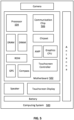
- Figure 1A is a cross sectional view taken across two example semiconductor devices 102 and 104, according to an embodiment of the present disclosure.
- Figure 1B is a top-down view of the adjacent semiconductor devices 102 and 104 where Figure 1A illustrates the cross section taken across the dotted line.
- MOS metal oxide semiconductor
- GAA gate-all-around
- Semiconductor devices 102 and 104 represent a portion of an integrated circuit that may contain any number of similar semiconductor devices. In some embodiments, semiconductor devices 102 and 104 represent dummy devices that are present along a standard cell boundary and are biased in a permanent off state.
- semiconductor devices 102 and 104 are formed on a substrate 101. Any number of semiconductor devices can be formed on substrate 101, but two are used here as an example.
- Substrate 101 can be, for example, a bulk substrate including group IV semiconductor material (such as silicon, germanium, or silicon germanium), group III-V semiconductor material (such as gallium arsenide, indium gallium arsenide, or indium phosphide), and/or any other suitable material upon which transistors can be formed.
- substrate 101 can be a semiconductor-on-insulator substrate having a desired semiconductor layer over a buried insulator layer (e.g., silicon over silicon dioxide).
- substrate 101 can be a multilayer substrate or superlattice suitable for forming nanowires or nanoribbons (e.g., alternating layers of silicon and SiGe, or alternating layers indium gallium arsenide and indium phosphide). Any number of substrates can be used.
- nanowires or nanoribbons e.g., alternating layers of silicon and SiGe, or alternating layers indium gallium arsenide and indium phosphide. Any number of substrates can be used.
- the semiconductor material in each of semiconductor devices 102 and 104 may be formed from substrate 101.
- Semiconductor devices 102 and 104 may each include fins or semiconductor material as nanowires or nanoribbons that can be, for example, native to substrate 101 (formed from the substrate itself).
- the fins or semiconductor material can be formed of material deposited onto an underlying substrate.
- a blanket layer of silicon germanium (SiGe) can be deposited onto a silicon substrate, and then patterned and etched to form a plurality of SiGe fins or nanoribbons.
- non-native fins can be formed in a so-called aspect ratio trapping based process, where native fins are etched away so as to leave fin-shaped trenches which can then be filled with an alternative semiconductor material (e.g., group IV or III-V material).
- the fins include alternating layers of material (e.g., alternating layers of silicon and SiGe) that facilitates forming of nanowires and nanoribbons during a gate forming process where one type of the alternating layers are selectively etched away so as to liberate the other type of alternating layers within the channel region, so that a gate-all-around (GAA) process can then be carried out.
- the alternating layers can be blanket deposited and then etched into fins, or deposited into fin-shaped trenches.
- Dielectric layer 106 that may include silicon oxide.
- Dielectric layer 106 provides shallow trench isolation (STI) between any adjacent semiconductor devices.
- Dielectric layer 106 can be any suitable dielectric material, such as silicon dioxide, aluminum oxide, or silicon oxycarbonitride.
- semiconductor device 102 includes a subfin region 108 and a semiconductor region that includes a plurality of nanoribbons 112 above the subfin region 108.
- subfin region 108 comprises the same semiconductor material as substrate 101 and is adjacent to dielectric layer 106.
- nanoribbons 112 extend between a source and a drain region to provide an active region for a transistor (e.g., the semiconductor region beneath the gate).
- Source and drain regions are not shown in the cross-section of Figure 1A , but are seen in the top-down view of Figure 1B where nanoribbons 112 of semiconductor device 102 extend between a source region 126a and a drain region 126b (similarly, the nanoribbons 112 of semiconductor device 104 extend between a source region 128a and a drain region 128b).
- Figure 1B also illustrates spacer structures 124 on either end of each of semiconductor device 102 and semiconductor device 104 as would be understood to a person skilled in the relevant art.
- Spacer structures 124 may include a dielectric material, such as silicon nitride.
- the source and drain regions are epitaxial regions that are provided using an etch-and-replace process.
- one or both of the source and drain regions could be, for example, implantation-doped native portions of the semiconductor fins or substrate.
- Any semiconductor materials suitable for source and drain regions can be used (e.g., group IV and group III-V semiconductor materials).
- the source and drain regions may include multiple layers such as liners and capping layers to improve contact resistance.
- the composition and doping of the source and drain regions may be the same or different, depending on the polarity of the transistors.
- one transistor is a p-type MOS (PMOS) transistor
- the other transistor is an n-type MOS (NMOS) transistor. Any number of source and drain configurations and materials can be used.
- one or more buried conductive layers 118a and 118b are provided within substrate 101 and adjacent to one or more of the semiconductor devices.
- buried conductive layer 118a is provided within a portion of substrate 101 adjacent to semiconductor device 102 and buried conductive layer 118b is provided within a portion of substrate 101 adjacent to semiconductor device 104.
- Each of buried conductive layers 118a and 118b are BPR structures that can be any conductive material, such as any metal or metal alloy, that may include any of tungsten, molybdenum, ruthenium, cobalt, copper, aluminum, or silver.
- semiconductor device 102 is an n-channel device and buried conductive layer 118a provides a VSS power rail while semiconductor device 104 is a p-channel device and buried conductive layer 118b provides a VDD power rail.
- liner dielectric layers (not shown) are provided on sidewalls of the buried conductive layers 118a/118b to provide electrical isolation between the buried conductive layers and any neighboring semiconductor devices.
- Each of buried conductive layers 118a and 118b may be below dielectric layer 106, or at least below a top surface of dielectric layer 106.
- nanoribbons 112 include a gate dielectric 114 that may include a single material layer or multiple stacked material layers.
- gate dielectric 114 includes a first dielectric layer such as silicon oxide and a second dielectric layer that includes a high-k material such as hafnium oxide, with the first dielectric layer being between a given nanoribbon 112 and the second dielectric layer.
- the hafnium oxide may be doped with an element, such as lanthanum, to affect the threshold voltage of the given semiconductor device.
- Gate dielectric 114 is present around each nanoribbon 112 and may also be present along the sidewalls of adjacent dielectric walls 110.
- dielectric walls 110 are present along sides of each of semiconductor devices 102 and 104. As seen more clearly in Figure 1B , dielectric wall 110 may extend parallel to the lengths of nanoribbons 212 (as they extend between the source and drain region) such that they act like traditional gate cut structures. In some other embodiments, dielectric wall 110 extends around all sides of each of semiconductor devices 102 and 104 such that a given semiconductor device can sit within its own "well" formed by four connecting dielectric walls. These dielectric walls 110 may include any composition of silicon and nitrogen or any other dielectric material that exhibits high etch selectivity to silicon oxide. Dielectric walls 110 can also act as gate cut structures that isolate neighboring semiconductor device gates from one another, such as the example illustrated in Figures 1A and 1B .
- each of semiconductor device 102 and 104 includes one or more conductive gate layers such as a first conductive gate layer 116a in semiconductor device 102 and a second conductive gate layer 116b in semiconductor device 104.
- first conductive gate layer 116a acts as a first work function gate around nanoribbons 112 of first semiconductor device 102 and second conductive gate layer 116b acts as a second work function gate around nanoribbons 112 of second semiconductor device 104.
- semiconductor device 102 is an n-channel device and first conductive gate layer 116a is an n-channel work function metal that includes titanium.
- first conductive gate layer 116a includes titanium, aluminum, carbon, and oxygen (TiAICO).
- semiconductor device 104 is a p-channel device and second conductive gate layer 116b is a p-channel work function metal that includes tungsten.
- first conductive gate layer 116a and second conductive gate layer 116b are the same conductive material. Other metals or sufficiently conductive materials may be used as well for either the n-channel or p-channel devices.
- a metal fill 120 may be present on both first conductive gate layer 116a and second conductive gate layer 116b.
- Metal fill 120 may include tungsten (W) or a combination of titanium nitride (TiN) and tungsten (W), to name a few examples.
- a first fill metal with a first material composition is used over semiconductor device 102 and a second fill metal with a second different material composition is used over semiconductor device 104.
- metal fill 120 also forms conductive vias 122a and 122b that extend through a thickness of dielectric layer 106 and contact corresponding buried conductive layers 118a and 118b. Description herein focuses on semiconductor device 102 with conductive via 122a, but it is equally applicable to semiconductor device 104 and conductive via 122b.
- Conductive via 122a may be formed adjacent to dielectric wall 110, adjacent semiconductor device 102, or at least between dielectric wall 110 and semiconductor device 102.
- Metal fill 120 may seamlessly cover the underlying first conductive gate layer 116a and extend into an opening formed through dielectric layer 106 to form conductive via 122a.
- conductive via 122a is illustrated as having straight walls, it should be understood that the walls may have a tapered profile, such as a narrowing profile as conductive via 122a extend towards buried conductive layer 118a.
- the width of conductive via 122a is determined by a thickness of the deposited first conductive gate layer 116a. That is, the etch used to form the via opening is self-aligned based on the presence of first conductive gate layer 116a along the sides of the etching region, as will be discussed in more detail herein.
- the width of conductive via 122a at its widest point is between about 8 nm and about 15 nm.
- the height of conductive via 122a depends on the thickness of dielectric layer 106 and may be between about 10 nm and about 30 nm.
- the top-down view of the structure seen in Figure 1B shows how a portion of the underlying buried conductive layers 118a and 118b are exposed following the via opening etch (e.g., before any metal fill is deposited). It should be noted that the top-down view is not drawn to scale in order to clearly label the various structures.
- Figures 2A - 2N include cross-sectional views that collectively illustrate an example process for forming an integrated circuit configured with semiconductor devices having gate tie down structures to buried conductive layers, in accordance with an embodiment of the present disclosure.
- Each figure shows an example structure that results from the process flow up to that point in time, so the depicted structure evolves as the process flow continues, culminating in the structure shown in Figure 2N , which is similar to the structure shown in Figure 1A .
- the illustrated integrated circuit structure may be part of a larger integrated circuit that includes other integrated circuitry not depicted.
- Example materials and process parameters are given, but the present disclosure is not intended to be limited to any specific such materials or parameters, as will be appreciated.
- Figure 2A illustrates a cross-sectional view taken through and perpendicular to a set of fins of semiconductor devices 120 and 104 extending from substrate 101, according to an embodiment of the present disclosure.
- the previous relevant discussion with respect to example configurations and materials for the substrate 101 and the fins as well as dielectric layer 106 is equally applicable here.
- the fins can be native to the substrate, as illustrated, or non-native to the substrate, or multi-layer fins suitable for forming nanowires or nanoribbons.
- the fins of semiconductor devices 102 and 104 include alternating layers of material in order to ultimately form nanowires or nanoribbons in a gate-all-around (GAA) structure.
- GAA gate-all-around
- the fins include a single semiconductor material (e.g., silicon or germanium) for a tri-gate or finFET structure.
- the fins can be alternating with respect to transistor polarity.
- the fin of semiconductor device 102 can include an NMOS material fin (e.g., silicon fin doped with p-type dopants) and the fin of semiconductor device 104 can include a PMOS material fin (e.g., SiGe fin or silicon fin doped with n-type dopants) for a first logic or memory cell.
- NMOS material fin e.g., silicon fin doped with p-type dopants
- PMOS material fin e.g., SiGe fin or silicon fin doped with n-type dopants
- Numerous other configurations can be used, including fins included in integrated circuit sections other than memory or logic sections, such as analog mixed signal sections, input/output sections, radio frequency or transducer sections.
- a cap layer 202 is left on the top of each fin.
- This cap layer 202 may have been used as a hard mask to pattern the fins during a reactive ion etching (RIE) process.
- RIE reactive ion etching
- the cap layer 202 may remain during subsequent processing steps to act as a dummy ribbon structure to protect the underlying semiconductor ribbons when forming the gate tie down structures.
- dielectric layer 106 is an oxide (e.g., silicon dioxide)
- cap layer 202 can be, for instance, a nitride, oxynitride, a carbide, or an oxycarbonitride so as to provide etch selectivity with respect to dielectric layer 106.
- each of the fins includes alternating layers of semiconductor material 203 and sacrificial layers 204.
- Semiconductor material 203 may include silicon, germanium, or an alloy thereof.
- Sacrificial layers 204 have a different material composition than semiconductor material 203.
- sacrificial layers 204 include some combination of silicon and germanium (SiGe).
- semiconductor material 203 will ultimately form the semiconductor regions that extend between a source and a drain region for each of semiconductor devices 102 and 104.
- Figure 2B depicts the cross-section view of the structure shown in Figure 2A following an etching process to create recesses where the buried power rails will be formed.
- a lithography mask (not shown) is patterned to expose the regions of the structure to be etched.
- the lithography mask can be any suitable mask such as, for instance, photoresist or one or more layers (e.g., carbon hard mask or an anti-reflective coating film or a silicon oxynitride) that provide the desired etch selectivity. Any number of wet and/or dry etching techniques can be used to etch the trenches where the buried power rails will be formed.
- the etch scheme includes a dielectric dry etch that is selective to cap layer 202, to remove any of dielectric layer 106 (e.g., silicon dioxide) exposed by the opening in the lithography mask.
- the example etch scheme includes an RIE process to etch the remainder of the trench within the substrate 101.
- the total height from the bottom of the etched trench in substrate 101 to the top of cap layer 202 can be 250 nm or more, with the portion of substrate 101 etched by RIE being in the range of 50 to 100 nm, and with the fins above having a height in the range of 50 to 200 nm (e.g., 60 to 100 nm), and the cap layer 202 having a height in the range of 5 to 10 nm.
- the width of the fins can be, for example, in the range of 5 to 40 nm.
- the pitch between neighboring fins can be, for example, in the range of 35 to 120 nm.
- a width-to-height aspect ratio of the fins is in the range of about 1:5 to 1:50, such as the specific example case where the fins are about 10 nm wide at their midpoint, and about 200 nm tall, so as to provide a 1:20 width-to-height aspect ratio.
- FIG. 2C depicts the cross-section view of the structure shown in Figure 2B following the formation of the buried power rails.
- Each of buried conductive layers 118a and 118b can be deposited by, for example, electroplating, electroless plating, chemical vapor deposition (CVD), physical vapor deposition (PVD) or atomic layer deposition (ALD). It should be noted that in some embodiments, a liner dielectric layer is deposited to cover the sidewalls of the etched trenches before depositing buried conductive layers 118a and 118b.
- any excess amount of buried conductive layers 118a/118b extending out of the trench can be polished away by way of a planarization/polishing technique such as chemical mechanical polishing (CMP).
- CMP chemical mechanical polishing
- the buried conductive layers 118a/118b can be recessed using an isotropic metal etch process selective to dielectric layer 106 and cap layer 202.
- the depth of the recess will depend on the desired height of the final buried power rails, but in some example cases is in the range of 50 to 250 nm (e.g., 70 to 130 nm).
- the height of the recessed buried conductive layers 118a/118b can vary as well, but in some example cases, is in the range of about 50 to 200 nm (e.g., 60 to 120 nm).
- buried conductive layers 118a/118b can be any number of conductive materials, such as tungsten, molybdenum, ruthenium, cobalt, copper, aluminum, silver, or alloys thereof. Although buried conductive layers 118a/118b are formed to be beneath the subfin portions 108 of the fins, this is not required and in some examples the buried conductive layers 118a/118b are formed adjacent to a portion of subfins 108. Further note that buried conductive layers 118a/118b can run parallel to the fins for any desired distance.
- Dielectric layer 107 is added over the buried conductive layers 118a/118b and planarized using, for example, CMP.
- Dielectric layer 107 may be the same as dielectric layer 106.
- Figure 2D depicts the cross-section view of the structure shown in Figure 2C following the recessing of dielectric layers 106 and 107.
- dielectric layers 106 and 107 are the same material such that the layers are recessed back together at the same rate using any suitable dry or wet etching process that is selective to layers 202-204.
- layer 202 includes a nitride (e.g., silicon nitride)
- the fins include silicon or germanium materials (e.g., layers 203 are silicon and layers 204 are SiGe)
- dielectric layers 106 and 107 are an oxide (e.g., silicon dioxide), so as to allow for a singular etch selectivity with respect to the fins.
- the total height of the fins that extend above dielectric layers 106 and 107 may be between 50 nm and 150 nm, and the width of the fins can be, for example, in the range of 5 to 100 nm.
- the thickness of each layer of semiconductor material 203 and sacrificial layer 204 may be between about 5 nm and about 25 nm.
- Figure 2E depicts the cross-section view of the structure shown in Figure 2D following the formation of a sacrificial gate 206.
- Sacrificial gate 206 may include any material that can be safely removed later in the process without etching or otherwise damaging any portions of the fins.
- sacrificial gate 206 includes polysilicon.
- sacrificial gate 206 extends over the top surfaces of cap layer 202.
- additional semiconductor device structures are formed that are not shown in these cross-sections. These additional structures include spacer structures on the edges of the sacrificial gate 206 and source and drain regions on either ends of each of the fins. The formation of such structures would be well understood to a person skilled in the relevant art.
- Figure 2F depicts the cross-section view of the structure shown in Figure 2E following the formation of dielectric walls 110 between adjacent fins.
- Another lithography mask (not shown) is patterned to expose the regions of sacrificial gate 206 to be etched away and replaced with dielectric material to form dielectric walls 110.
- the lithography mask can be any suitable mask such as, for instance, photoresist or one or more layers (e.g., carbon hard mask or an anti-reflective coating film or a silicon oxynitride) that provide the desired etch selectivity. Any wet or dry etching technique can be used to etch through sacrificial gate 206 and stop at the underlying dielectric layer 106/107.
- the trenches may be filled using a suitable dielectric material to from dielectric walls 110.
- the dielectric material is silicon nitride and is deposited using any one of CVD, PVD, or PECVD. Any excess dielectric material extending out from the trenches can be polished back using, for example, CMP
- Figure 2G depicts the cross-section view of the structure shown in Figure 2F following the removal of sacrificial gate 206. Any wet or dry etching process may be used to remove sacrificial gate 206 while maintaining the semiconductor material present within the fins. Furthermore, dielectric walls 110 remain following the removal of sacrificial gate 206.
- Figure 2H depicts the cross-section view of the structure shown in Figure 2G following the removal of sacrificial layers 204 from the fins.
- sacrificial layers 204 are removed using a selective isotropic etching process that removes the material of sacrificial layers 204 but does not remove (or removes very little of) the layers of semiconductor material 203.
- the exposed layers of semiconductor material 203 form nanoribbons 112 that extend between source and drain regions in each of semiconductor device 102 and 104.
- cap layer 202 also remains as a dummy ribbon extending in the same direction as each of the lower nanoribbons 203.
- the distance between cap layer 202 and the adjacent lower nanoribbon 112 is larger than the distance between any pair of adjacent nanoribbons in the same nanoribbon stack.
- Gate dielectric 114 may include any suitable dielectric (such as silicon dioxide, and/or a high-k dielectric material).
- suitable dielectric such as silicon dioxide, and/or a high-k dielectric material.
- high-k dielectric materials include, for instance, hafnium oxide, hafnium silicon oxide, lanthanum oxide, lanthanum aluminum oxide, zirconium oxide, zirconium silicon oxide, tantalum oxide, titanium oxide, barium strontium titanium oxide, barium titanium oxide, strontium titanium oxide, yttrium oxide, aluminum oxide, lead scandium tantalum oxide, and lead zinc niobate, to provide some examples.
- gate dielectric 114 is hafnium oxide with a thickness between about 2 nm and about 10 nm.
- gate dielectric 114 may include one or more silicates (e.g., titanium silicate, tungsten silicate, niobium silicate, and silicates of other transition metals).
- Gate dielectric 114 may be a multilayer structure, in some examples.
- gate dielectric 114 may include a first layer on nanoribbons 112, and a second layer on the first layer.
- the first layer can be, for instance, an oxide of nanoribbons 112 (e.g., silicon dioxide) and the second layer can be a high-k dielectric material (e.g., hafnium oxide).
- an annealing process may be carried out on gate dielectric 114 to improve its quality or to drive in dopants when high-k dielectric material is used.
- Figure 2J depicts the cross-section view of the structure shown in Figure 21 following the formation of conductive layers 116a and 116b.
- both conductive layers 116a and 116b are the same material (e.g., deposited together during the same deposition process) and may include titanium or tungsten.
- semiconductor device 102 is an n-channel device and first conductive layer 116a is an n-channel work function metal that includes titanium.
- first conductive layer 116a includes titanium, aluminum, carbon, and oxygen (TiAICO).
- semiconductor device 104 is a p-channel device and second conductive layer 116b is a p-channel work function metal that includes tungsten.
- Conductive layers 116a and 116b may be deposited using any known metal deposition technique, such as CVD, ALD, or PECVD. Each of conductive layers 116a and 116b may have a deposited thickness between about 0.5 nm and about 5 nm. In some embodiments, conductive layers 116a and 116b are deposited to a thickness sufficient enough to fill the voids between adjacent nanoribbons of the corresponding semiconductor device. Conductive layers 116a and 116b are also formed along the sidewalls of any adjacent dielectric walls 110. Following the deposition of conductive layers 116a and 116b, a dielectric fill may be deposited to fill the spaces between the nanoribbon stacks and dielectric walls 110.
- the dielectric fill is silicon oxide although any other dielectric materials may be used as well.
- any excess dielectric fill above the top surface of dielectric wall 110 is removed along with any portion of conductive layers 116a or 116b over the top surface of dielectric wall 110. Polishing may be performed using one or more rounds of chemical mechanical polishing (CMP) to produce a planarized top surface.
- CMP chemical mechanical polishing
- the dielectric fill is subsequently removed using any wet or dry isotropic dielectric etching procedure.
- Figure 2K depicts the cross-section view of the structure shown in Figure 2J following the formation of masking layer 208.
- masking layer 208 is patterned to provide openings between the nanoribbon stack and an adjacent dielectric wall of each of semiconductor devices 102 and 104.
- the openings in masking layer 208 are aligned over at least a portion of buried conductive layers 118a and 118b.
- Masking layer 208 can be any suitable mask material used for lithography purposes such as, for instance, photoresist or one or more layers (e.g., carbon hard mask or an anti-reflective coating film or a silicon oxynitride) that provide the desired etch selectivity to allow for forming the gate tie-down vias. Note how masking layer 208 need not be perfectly aligned to the edges of conductive layers 116a and 116b.
- Figure 2L depicts the cross-section view of the structure shown in Figure 2K following one or more etching processes to form via openings 210a and 210b.
- a series of anisotropic RIE processes may be performed to punch through the different material layers and form via openings 210a and 210b through the thickness of dielectric layer 107.
- a first RIE process may be used to punch through each of conductive layers 116a and 116b.
- the top corners of the exposed conductive layers 116a and 116b may also be removed.
- this corner removal of conductive layers 116a and 116b is not a concern as any damage would only be caused to the dummy ribbon formed from cap layer 202.
- a second RIE process may be used to punch through gate dielectric 114.
- the same RIE process is used to etch through gate dielectric 114 and form via openings 210a and 210b.
- a different RIE process is used to etch through dielectric layer 107 than the one used to punch through gate dielectric 114.
- the etching process is complete once the underlying buried conductive layers 118a and 118b are exposed by the etching process. Note that the semiconductor nanoribbons 112 are protected from the etch by virtue of the dummy nanoribbon structure formed by gate layer 202.
- etched via openings 210a and 210b are aligned adjacent to sidewalls of dielectric walls 110. In some embodiments, etched via openings 210a and 210b are aligned directly along one or more material layers on the sidewalls of dielectric walls 110, such as gate dielectric 114 and/or conductive layers 116a/116b.
- via opening 210a is formed directly between the portion of conductive layer 116a on the sidewall of dielectric wall 110 and the portion of conductive layer 116a around nanoribbons 112 of semiconductor device 102
- via opening 210b is formed directly between the portion of conductive layer 116b on the sidewall of dielectric wall 110 and the portion of conductive layer 116b around nanoribbons 112 of semiconductor device 104.
- Figure 2M depicts the cross-section view of the structure shown in Figure 2L following the deposition of metal fill 120.
- the same metal fill 120 is present on both first conductive layer 116a and second conductive layer 116b.
- Metal fill 120 may include tungsten (W) or a combination of titanium nitride (TiN) and tungsten (W), to name a few examples.
- a first fill metal with a first material composition is deposited over first conductive layer 116a and a second fill metal with a second different material composition is deposited over second conductive layer 116b.
- Depositing metal fill 120 around first conductive layer 116a and second conductive layer 116b also causes metal fill 120 to enter into via openings 210a and 210b and form conductive vias 122a and 122b, respectively, which extend through a thickness of dielectric layer 107 and contact corresponding buried conductive layers 118a and 118b.
- metal fill 120 seamlessly transitions between contacting first conductive layer 116a and buried conductive layer 118a by way of conductive via 122a, and seamlessly transitions between contacting second conductive layer 116b and buried conductive layer 118b by way of conductive via 122b.
- Figure 2N depicts the cross-section view of the structure shown in Figure 2M following a polishing process to remove excess metal fill 120.
- the polishing planarizes the structure and removes any excess metal fill 120 to prevent it from causing an electrical short between different semiconductor devices. Any number of CMP processes may be performed to planarize the structure.
- the structure is polished until cap layer 202 is reached, this leaving behind at least a portion of cap layer 202 and the corresponding dummy ribbon. In some other embodiments, the structure is polished down low enough that cap layer 202 is fully removed.
- FIG. 3 illustrates an example embodiment of a chip package 300, in accordance with an embodiment of the present disclosure.
- chip package 300 includes one or more dies 302.
- One or more dies 302 may include at least one integrated circuit having semiconductor devices, such as any of the semiconductor devices disclosed herein.
- One or more dies 302 may include any other circuitry used to interface with other devices formed on the dies, or other devices connected to chip package 300, in some example configurations.
- chip package 300 includes a housing 304 that is bonded to a package substrate 306.
- the housing 304 may be any standard or proprietary housing, and may provide, for example, electromagnetic shielding and environmental protection for the components of chip package 300.
- the one or more dies 302 may be conductively coupled to a package substrate 306 using connections 308, which may be implemented with any number of standard or proprietary connection mechanisms, such as solder bumps, ball grid array (BGA), pins, or wire bonds, to name a few examples.
- Package substrate 306 may be any standard or proprietary package substrate, but in some cases includes a dielectric material having conductive pathways (e.g., including conductive vias and lines) extending through the dielectric material between the faces of package substrate 306, or between different locations on each face.
- package substrate 306 may have a thickness less than 1 millimeter (e.g., between 0.1 millimeters and 0.5 millimeters), although any number of package geometries can be used. Additional conductive contacts 312 may be disposed at an opposite face of package substrate 306 for conductively contacting, for instance, a printed circuit board (PCB). One or more vias 310 extend through a thickness of package substrate 306 to provide conductive pathways between one or more of connections 308 to one or more of contacts 312.
- PCB printed circuit board
- Vias 310 are illustrated as single straight columns through package substrate 306 for ease of illustration, although other configurations can be used (e.g., damascene, dual damascene, through-silicon via, or an interconnect structure that meanders through the thickness of substrate 306 to contact one or more intermediate locations therein).
- vias 310 are fabricated by multiple smaller stacked vias, or are staggered at different locations across package substrate 306.
- contacts 312 are solder balls (e.g., for bump-based connections or a ball grid array arrangement), but any suitable package bonding mechanism may be used (e.g., pins in a pin grid array arrangement or lands in a land grid array arrangement).
- a solder resist is disposed between contacts 312, to inhibit shorting.
- a mold material 314 may be disposed around the one or more dies 302 included within housing 304 (e.g., between dies 302 and package substrate 306 as an underfill material, as well as between dies 302 and housing 304 as an overfill material). Although the dimensions and qualities of the mold material 314 can vary from one embodiment to the next, in some embodiments, a thickness of mold material 314 is less than 1 millimeter.
- Example materials that may be used for mold material 314 include epoxy mold materials, as suitable. In some cases, the mold material 314 is thermally conductive, in addition to being electrically insulating.
- Figure 4 is a flow chart of a method 400 for forming at least a portion of an integrated circuit, according to an embodiment.
- Various operations of method 400 may be illustrated in Figures 2A - 2N .
- the correlation of the various operations of method 400 to the specific components illustrated in the aforementioned figures is not intended to imply any structural and/or use limitations. Rather, the aforementioned figures provide one example embodiment of method 400.
- Other operations may be performed before, during, or after any of the operations of method 400.
- method 400 does not explicitly describe many steps that are performed to form common transistor structures. Some of the operations of method 400 may be performed in a different order than the illustrated order.
- Method 400 begins with operation 402 where semiconductor fins are formed with a cap layer over the fins.
- the fins can be native to the underlying substrate or non-native to the substrate, or multi-layer fins suitable for forming nanowires or nanoribbons.
- the fins include alternating layers of material in order to ultimately form nanowires or nanoribbons in a gate-all-around (GAA) structure.
- the fins include a single semiconductor material (e.g., silicon or germanium) for a tri-gate or finFET structure. Numerous other configurations can be used, including fins included in integrated circuit sections other than memory or logic sections.
- the cap layer that is used to pattern the location of the fins is left on the top of each fin.
- the cap layer may remain during subsequent processing steps to act as a dummy structure to protect the underlying semiconductor ribbons (or fin) when forming the gate tie down structures.
- the cap layer can be, for instance, a nitride, oxynitride, a carbide, or an oxycarbonitride so as to provide etch selectivity with respect to surrounding dielectric fill layers.
- Method 400 continues with operation 404 where buried conductive layers are formed in the substrate to act as buried power rails.
- Any number of wet and/or dry etching techniques can be used to etch trenches through dielectric fill layers and through a portion of the substrate to define areas where the buried power rails will be formed.
- the etch scheme may include a dielectric dry etch that is selective to the cap layer followed by an RIE process to etch the remainder of the trench through the substrate.
- conductive material can be deposited within the trenches by, for example, electroplating, electroless plating, CVD, PECVD or ALD.
- the conductive material can be any number of conductive materials, such as tungsten, molybdenum, ruthenium, cobalt, copper, aluminum, silver, or alloys thereof.
- a liner dielectric layer is deposited to cover the sidewalls of the etched trenches before depositing the conductive material. Any excess amount of conductive material extending out of the trench can be polished away by way of a planarization/polishing technique such as CMP.
- the conductive material is recessed using, for example, an isotropic metal etch process selective to any surrounding dielectric materials.
- the depth of the recess will depend on the desired height of the final buried conductive layers, but in some example cases is in the range of 20 to 200 nm (e.g., 50 to 130 nm).
- the height of the recessed buried conductive layers can vary as well, but in some example cases, is in the range of about 20 to 500 nm (e.g., 30 to 90 nm).
- Method 400 continues with operation 406 where a dielectric layer is formed over the buried conductive layers.
- another dielectric fill is added over the buried conductive layers and subsequently recessed to form a thinner dielectric layer over the buried conductive layers.
- the fins include silicon or germanium materials, and the fill is an oxide (e.g., silicon dioxide), so as to allow for a singular etch selectivity with respect to the fins. While dimensions can vary from one example embodiment to the next, in one example case, the total height of the fins that extend above the recessed dielectric layer may be between 50 nm and 150 nm, and the width of the fins can be, for example, in the range of 5 to 100 nm.
- transistor structures such as the formation of source and drain regions, removal of sacrificial layers to form nanoribbons (in the case of GAA structures), and formation of a gate dielectric layer over the semiconductor regions of the fin or nanoribbons in each semiconductor device.
- Method 400 continues with operation 408 where conductive layers are formed over the semiconductor material (e.g., over the semiconductor fins or over the semiconductor nanoribbons). Note that the conductive layers are also formed over the cap layer that has remained as part of the structure above the semiconductor material.
- the conductive layers may act as work function metal layers and provide gate electrodes for the transistors.
- one or more of the conductive layers includes titanium.
- one or more of the conductive layers includes titanium, aluminum, carbon, and oxygen (TiAICO).
- one or more of the conductive layers includes tungsten.
- the conductive layers may be deposited using any known metal deposition technique, such as CVD, ALD, or PECVD. Each of the conductive layers may have a deposited thickness between about 0.5 nm and about 5 nm. In some embodiments, the conductive layers are deposited to a thickness sufficient enough to fill the voids between adjacent nanoribbons of the corresponding semiconductor device (e.g., in GAA structures).
- Method 400 continues with operation 410 where gate tie-down via openings are formed through the dielectric layer over the buried conductive layers.
- a series of anisotropic RIE processes may be performed to punch through different material layers to form the via openings through the thickness of the dielectric layer above the buried conductive layers.
- a first RIE process may be used to punch through a portion of the conductive layers that act as the work function gate electrodes. During this etching process, the top corners of the exposed conductive layers may also be removed. However, this corner removal of conductive layers 116a and 116b is not a concern as any damage would only be caused to the dummy structure formed from the cap layer.
- a second RIE process may be used to punch through a portion of the gate dielectric.
- the same RIE process is used to etch through the gate dielectric and form the via openings through the dielectric layer.
- a different RIE process is used to etch through the dielectric layer than the one used to punch through the gate dielectric.
- the etching process is complete once the underlying buried conductive layers are exposed by the etching process.
- Method 400 continues with operation 412 where conductive material is formed over the semiconductor material and in the via opening to form conductive vias.
- the semiconductor material may be in the shape of a fin or of nanowires. According to some embodiments, the same deposited conductive material is present on both the first conductive layer and the second conductive layer.
- the conductive material may include a metal such as tungsten (W) or a combination of titanium nitride (TiN) and tungsten (W), to name a few examples.
- Depositing the conductive material around the conductive layers also causes the conductive material to enter into the via openings and form the conductive vias that contact the buried conductive layers.
- the conductive material seamlessly transitions between contacting the conductive layers and the buried conductive layers to electrically tie the gate electrodes of the corresponding semiconductor devices to buried power rails.
- FIG. 5 is an example computing system implemented with one or more of the integrated circuit structures as disclosed herein, in accordance with some embodiments of the present disclosure.
- the computing system 500 houses a motherboard 502.
- the motherboard 502 may include a number of components, including, but not limited to, a processor 504 and at least one communication chip 506, each of which can be physically and electrically coupled to the motherboard 502, or otherwise integrated therein.
- the motherboard 502 may be, for example, any printed circuit board (PCB), whether a main board, a daughterboard mounted on a main board, or the only board of system 500, etc.
- PCB printed circuit board
- computing system 500 may include one or more other components that may or may not be physically and electrically coupled to the motherboard 502. These other components may include, but are not limited to, volatile memory (e.g., DRAM), non-volatile memory (e.g., ROM), a graphics processor, a digital signal processor, a crypto processor, a chipset, an antenna, a display, a touchscreen display, a touchscreen controller, a battery, an audio codec, a video codec, a power amplifier, a global positioning system (GPS) device, a compass, an accelerometer, a gyroscope, a speaker, a camera, and a mass storage device (such as hard disk drive, compact disk (CD), digital versatile disk (DVD), and so forth).
- volatile memory e.g., DRAM
- non-volatile memory e.g., ROM
- graphics processor e.g., a digital signal processor
- crypto processor e.g., a graphics processor
- a digital signal processor
- any of the components included in computing system 500 may include one or more integrated circuit structures or devices configured in accordance with an example embodiment (e.g., a module including an integrated circuit on a substrate, the substrate having semiconductor devices with their gates tied to buried power rails through conductive vias, as variously provided herein).
- multiple functions can be integrated into one or more chips (e.g., for instance, note that the communication chip 506 can be part of or otherwise integrated into the processor 504).
- the communication chip 506 enables wireless communications for the transfer of data to and from the computing system 500.
- wireless and its derivatives may be used to describe circuits, devices, systems, methods, techniques, communications channels, etc., that may communicate data through the use of modulated electromagnetic radiation through a non-solid medium. The term does not imply that the associated devices do not contain any wires, although in some embodiments they might not.
- the communication chip 506 may implement any of a number of wireless standards or protocols, including, but not limited to, Wi-Fi (IEEE 802.11 family), WiMAX (IEEE 802.16 family), IEEE 802.20, long term evolution (LTE), Ev-DO, HSPA+, HSDPA+, HSUPA+, EDGE, GSM, GPRS, CDMA, TDMA, DECT, Bluetooth, derivatives thereof, as well as any other wireless protocols that are designated as 3G, 4G, 5G, and beyond.
- the computing system 500 may include a plurality of communication chips 506.
- a first communication chip 506 may be dedicated to shorter range wireless communications such as Wi-Fi and Bluetooth and a second communication chip 506 may be dedicated to longer range wireless communications such as GPS, EDGE, GPRS, CDMA, WiMAX, LTE, Ev-DO, and others.
- the processor 504 of the computing system 500 includes an integrated circuit die packaged within the processor 504.
- the integrated circuit die of the processor includes onboard circuitry that is implemented with one or more semiconductor devices as variously described herein.
- the term "processor" may refer to any device or portion of a device that processes, for instance, electronic data from registers and/or memory to transform that electronic data into other electronic data that may be stored in registers and/or memory.
- the communication chip 506 also may include an integrated circuit die packaged within the communication chip 506.
- the integrated circuit die of the communication chip includes one or more semiconductor devices as variously described herein.
- multi-standard wireless capability may be integrated directly into the processor 504 (e.g., where functionality of any chips 506 is integrated into processor 504, rather than having separate communication chips).
- processor 504 may be a chip set having such wireless capability.
- any number of processor 504 and/or communication chips 506 can be used.
- any one chip or chip set can have multiple functions integrated therein.
- the computing system 500 may be a laptop, a netbook, a notebook, a smartphone, a tablet, a personal digital assistant (PDA), an ultra-mobile PC, a mobile phone, a desktop computer, a server, a printer, a scanner, a monitor, a set-top box, an entertainment control unit, a digital camera, a portable music player, a digital video recorder, or any other electronic device that processes data or employs one or more integrated circuit structures or devices formed using the disclosed techniques, as variously described herein.
- PDA personal digital assistant
- the various components of the computing system 500 may be combined or integrated in a system-on-a-chip (SoC) architecture.
- the components may be hardware components, firmware components, software components or any suitable combination of hardware, firmware or software.
Landscapes
- Engineering & Computer Science (AREA)
- Power Engineering (AREA)
- Microelectronics & Electronic Packaging (AREA)
- Physics & Mathematics (AREA)
- Condensed Matter Physics & Semiconductors (AREA)
- General Physics & Mathematics (AREA)
- Computer Hardware Design (AREA)
- Ceramic Engineering (AREA)
- Manufacturing & Machinery (AREA)
- Chemical & Material Sciences (AREA)
- Nanotechnology (AREA)
- Crystallography & Structural Chemistry (AREA)
- Geometry (AREA)
- Materials Engineering (AREA)
- Insulated Gate Type Field-Effect Transistor (AREA)
- Electrodes Of Semiconductors (AREA)
- Thin Film Transistor (AREA)
Abstract
Description
- The present disclosure relates to integrated circuits, and more particularly, to transistor gate connections to buried or backside power rails.
- As integrated circuits continue to scale downward in size, a number of challenges arise. For instance, reducing the size of memory and logic cells is becoming increasingly more difficult. One possible solution that can be used to allow further scaling of cell size includes buried or backside power rail technology, or more generally BPR technology. In some cases, BPR technology includes burying of conductors that deliver power (sometimes called power rails) to cells below the back end of line (BEOL) metal layers, usually in the same level as the device layer that includes semiconductor fins. In other cases, BPR technology includes forming such power rails on the backside of the substrate underneath the device layer. Such BPR configurations free-up overhead to make more room for logic connections and enable further scaling of a standard logic cell (e.g., memory and logic cells). BPR configurations also allow for relatively larger power rails (e.g., thicker), which in turn exhibit lower resistance and power dissipation. However, there remain a number of nontrivial challenges with respect to forming connections to such BPR structures.
-
-
Figures 1A and 1B are cross-sectional and plan views of some semiconductor devices that illustrate gate tie structures to buried or backside power (BPR) rails, in accordance with an embodiment of the present disclosure. -
Figures 2A - 2N are cross-section views that illustrate various stages in an example process for forming the gate tie structures ofFigures 1A and 1B , in accordance with some embodiments of the present disclosure. -
Figure 3 illustrates a cross-section view of a chip package containing one or more semiconductor dies, in accordance with some embodiments of the present disclosure. -
Figure 4 is a flowchart of a fabrication process for semiconductor devices having gate tie structures, in accordance with an embodiment of the present disclosure. -
Figure 5 illustrates a computing system including one or more integrated circuits, as variously described herein, in accordance with an embodiment of the present disclosure. - Although the following Detailed Description will proceed with reference being made to illustrative embodiments, many alternatives, modifications, and variations thereof will be apparent in light of this disclosure. As will be further appreciated, the figures are not necessarily drawn to scale or intended to limit the present disclosure to the specific configurations shown. For instance, while some figures generally indicate perfectly straight lines, right angles, and smooth surfaces, an actual implementation of an integrated circuit structure may have less than perfect straight lines, right angles, and some features may have surface topology or otherwise be non-smooth, given real world limitations of the processing equipment and techniques used.
- Techniques are provided herein to form semiconductor devices having gate tie structures between the device gate and a buried or backside power rail (BPR). The techniques can be used in any number of integrated circuit applications and are particularly useful with respect to logic and memory cells, such as those cells that use finFETs or gate-all-around (GAA) transistors. In an example, a semiconductor device includes a conductive material that is part of a transistor gate structure around or otherwise on a semiconductor region. The semiconductor region can be, for example, a fin of semiconductor material that extends between a source region and a drain region, or one or more nanowires or nanoribbons of semiconductor material that extend between a source region and a drain region. The gate structure includes a gate dielectric (e.g., high-k gate dielectric material) and a gate electrode (e.g., conductive material such as work function material and/or gate fill metal). A BPR structure is beneath a dielectric layer that is between the BPR structure and the conductive material of the gate structure. According to some such embodiments, the conductive material of the gate structure also extends through the dielectric material and contacts the BPR structure. In this manner, the portion of the conductive material that extends through the dielectric material effectively provides a via between the gate structure and the underlying BPR structure. Accordingly, the transistor gate of the semiconductor device can be biased with the power rail voltage supplied by the BPR structure. Note that the via may be self-aligned given the selective nature of the etch process that creates the hole or trench that passes through the dielectric material. Further note the continuous nature of the conductive material, according to some embodiments, in which there is no seam between the gate portion of the conductive material and the via portion of the conductive material (e.g., one continuous body of tungsten or other metal). In some embodiments, the gate electrode includes a work function layer that is on the underlying gate dielectric, and further includes a metal fill layer on the work function layer, wherein the metal fill layer also provides the via to the underlying BPR structure. Numerous variations and embodiments will be apparent in light of this disclosure.
- In many integrated circuit layouts, one or more of the transistors that are formed at the edges of cell boundaries are dummy devices (also known as gate-tied down devices) that have the same structure as the other transistors used within the cell, but have their gates tied to either power rails (e.g., VDD or VSS) or ground. Accordingly, such dummy devices are biased to provide isolation between different standard cells in the integrated circuit layout. For example, n-channel devices may have their gates tied to VSS to be biased off while p-channel devices may have their gates tied to VDD to be biased off. In situations where the power rails (e.g., VDD and VSS) are provided in the interconnect layers above the substrate, top-side contacts are used to connect the transistor gates to the corresponding power rails. However, this is not possible when the power rails are buried below the surface of the substrate, or provisioned on the backside of the substrate (e.g., both generally referred to herein as BPR structures).
- Thus, and in accordance with an embodiment of the present disclosure, techniques are provided herein to form transistor gate connections to BPR structures. In some cases, the techniques can be used to form self-aligned contact structures between the gates of dummy devices and BPR structures. In one example, neighboring n-channel and p-channel semiconductor devices may have their gates tied down to separate underlying BPR structures to supply VSS and VDD power, respectively, to the gates of the n-channel and p-channel semiconductor devices. According to some embodiments, via openings may be etched through an underlying dielectric layer to expose the BPR structures and the via opening etch may be self-aligned based on the position of a conductive layer earlier-deposited over the semiconductor regions of the semiconductor devices. In some embodiments, the conductive layer is part of the gate structure and acts as a work function metal around the semiconductor regions. Such work function metal can be deposited, for instance, on a high-k gate dielectric, in some embodiments. Once the via openings have been formed, a fill metal is deposited on the conductive layer and within the via openings to contact the underlying BPR structures and provide electrical coupling between the gate of a given semiconductor device and the corresponding BPR structure. In this manner, the fill metal not only provides part of the gate electrode but also provides a via from the gate electrode to the underlying BPR, such that the fill metal of the gate electrode and the via is a continuous body of metal. Once the via opening has been filled with a conductive material (e.g., with a fill metal) it may be referred to herein as a conductive via.
- According to an embodiment, an integrated circuit includes a substrate, a dielectric layer on the substrate, a semiconductor device having at least a portion extending above a top surface of the dielectric layer and having a semiconductor region extending between a source region and a drain region, a buried conductive layer below the top surface of the dielectric layer within the substrate, a conductive material around the semiconductor region, and a via opening through the dielectric layer. The conductive material is also in the via opening to form a conductive via that contacts the buried conductive layer.
- According to an embodiment, an electronic device includes a chip package having one or more dies. At least one of the one or more dies includes a dielectric layer, a semiconductor device having at least a portion extending above a top surface of the dielectric layer and having a semiconductor region extending between a source region and a drain region, a buried conductive layer below the top surface of the dielectric layer, a conductive material around the semiconductor region, and a via opening through the dielectric layer. The conductive material is also in the via opening to form a conductive via that contacts the buried conductive layer.
- According to another embodiment, a method of forming an integrated circuit includes forming a fin structure extending above a substrate, the fin structure comprising semiconductor material; forming a buried conductive layer adjacent to the fin structure and within the substrate, or below the substrate; forming a dielectric layer above the buried conductive layer, at least a portion of the fin structure extending above a top surface of the dielectric layer; forming a via opening through the dielectric layer to expose the buried conductive layer, the via opening adjacent to the fin structure; and forming a conductive material around the semiconductor material and in the via opening, such that the conductive material contacts the buried conductive layer.
- The techniques can be used with any type of planar and non-planar transistors, including finFETs (sometimes called double-gate transistors, or tri-gate transistors), or nanowire and nanoribbon transistors (sometimes called gate-all-around transistors), to name a few examples. The source and drain regions can be, for example, doped portions of a given fin or substrate, or epitaxial regions that are deposited during an etch-and-replace source/drain forming process. The dopant-type in the source and drain regions will depend on the polarity of the corresponding transistor. The gate structure can be implemented with a gate-first process or a gate-last process (sometimes called a replacement metal gate, or RMG, process). Any number of semiconductor materials can be used in forming the transistors, such as group IV materials (e.g., silicon, germanium, silicon germanium) or group III-V materials (e.g., gallium arsenide, indium gallium arsenide).
- Use of the techniques and structures provided herein may be detectable using tools such as electron microscopy including scanning/transmission electron microscopy (SEM/TEM), scanning transmission electron microscopy (STEM), nano-beam electron diffraction (NBD or NBED), and reflection electron microscopy (REM); composition mapping; x-ray crystallography or diffraction (XRD); energy-dispersive x-ray spectroscopy (EDX); secondary ion mass spectrometry (SIMS); time-of-flight SIMS (ToF-SIMS); atom probe imaging or tomography; local electrode atom probe (LEAP) techniques; 3D tomography; or high resolution physical or chemical analysis, to name a few suitable example analytical tools. For instance, in some example embodiments, such tools may indicate the presence of a conductive via extending between the gate structure on the semiconductor region of a transistor and a BPR structure, wherein a portion of the gate electrode and the conductive via are a continuous body of metal (e.g., a body of tungsten or cobalt or ruthenium or an alloy). The BPR structure may be on an opposite side of the transistor from other interconnect layers that provide logic signals between the active transistors of the integrated circuit. In some embodiments, the conductive vias are observed on dummy devices located along one or more edges of a standard cell layout. Numerous configurations and variations will be apparent in light of this disclosure.
- As used herein, the term "backside" generally refers to the area beneath one or more semiconductor devices (below the device layer) either within the device substrate or in the region of the device substrate (in the case where the bulk of the device substrate has been removed). Note that the backside may become a frontside, and vice-versa, if a given structure is flipped. To this end, and as will be appreciated, the use of terms like "above" "below" "beneath" "upper" "lower" "top" and "bottom" are used to facilitate discussion and are not intended to implicate a rigid structure or fixed orientation; rather such terms merely indicate spatial relationships when the structure is in a given orientation.
-
Figure 1A is a cross sectional view taken across twoexample semiconductor devices Figure 1B is a top-down view of theadjacent semiconductor devices Figure 1A illustrates the cross section taken across the dotted line. It should be noted that some of the material layers (such asconductive layers Figure 1B have been omitted for clarity. Each ofsemiconductor devices Semiconductor devices semiconductor devices - As can be seen,
semiconductor devices substrate 101. Any number of semiconductor devices can be formed onsubstrate 101, but two are used here as an example.Substrate 101 can be, for example, a bulk substrate including group IV semiconductor material (such as silicon, germanium, or silicon germanium), group III-V semiconductor material (such as gallium arsenide, indium gallium arsenide, or indium phosphide), and/or any other suitable material upon which transistors can be formed. Alternatively,substrate 101 can be a semiconductor-on-insulator substrate having a desired semiconductor layer over a buried insulator layer (e.g., silicon over silicon dioxide). Alternatively,substrate 101 can be a multilayer substrate or superlattice suitable for forming nanowires or nanoribbons (e.g., alternating layers of silicon and SiGe, or alternating layers indium gallium arsenide and indium phosphide). Any number of substrates can be used. - The semiconductor material in each of
semiconductor devices substrate 101.Semiconductor devices - As can further be seen, adjacent semiconductor devices are separated by a
dielectric layer 106 that may include silicon oxide.Dielectric layer 106 provides shallow trench isolation (STI) between any adjacent semiconductor devices.Dielectric layer 106 can be any suitable dielectric material, such as silicon dioxide, aluminum oxide, or silicon oxycarbonitride. - Focusing on
semiconductor device 102, but also applicable tosemiconductor device 104,semiconductor device 102 includes asubfin region 108 and a semiconductor region that includes a plurality ofnanoribbons 112 above thesubfin region 108. According to some embodiments,subfin region 108 comprises the same semiconductor material assubstrate 101 and is adjacent todielectric layer 106. According to some embodiments,nanoribbons 112 extend between a source and a drain region to provide an active region for a transistor (e.g., the semiconductor region beneath the gate). The source and drain regions are not shown in the cross-section ofFigure 1A , but are seen in the top-down view ofFigure 1B wherenanoribbons 112 ofsemiconductor device 102 extend between asource region 126a and adrain region 126b (similarly, thenanoribbons 112 ofsemiconductor device 104 extend between asource region 128a and adrain region 128b).Figure 1B also illustratesspacer structures 124 on either end of each ofsemiconductor device 102 andsemiconductor device 104 as would be understood to a person skilled in the relevant art.Spacer structures 124 may include a dielectric material, such as silicon nitride. - According to some embodiments, the source and drain regions are epitaxial regions that are provided using an etch-and-replace process. In other embodiments one or both of the source and drain regions could be, for example, implantation-doped native portions of the semiconductor fins or substrate. Any semiconductor materials suitable for source and drain regions can be used (e.g., group IV and group III-V semiconductor materials). The source and drain regions may include multiple layers such as liners and capping layers to improve contact resistance. In any such cases, the composition and doping of the source and drain regions may be the same or different, depending on the polarity of the transistors. In an example, for instance, one transistor is a p-type MOS (PMOS) transistor, and the other transistor is an n-type MOS (NMOS) transistor. Any number of source and drain configurations and materials can be used.
- In some embodiments, one or more buried
conductive layers substrate 101 and adjacent to one or more of the semiconductor devices. In the illustrated example, buriedconductive layer 118a is provided within a portion ofsubstrate 101 adjacent tosemiconductor device 102 and buriedconductive layer 118b is provided within a portion ofsubstrate 101 adjacent tosemiconductor device 104. Each of buriedconductive layers semiconductor device 102 is an n-channel device and buriedconductive layer 118a provides a VSS power rail whilesemiconductor device 104 is a p-channel device and buriedconductive layer 118b provides a VDD power rail. According to some embodiments, liner dielectric layers (not shown) are provided on sidewalls of the buriedconductive layers 118a/118b to provide electrical isolation between the buried conductive layers and any neighboring semiconductor devices. Each of buriedconductive layers dielectric layer 106, or at least below a top surface ofdielectric layer 106. - Focusing again on
semiconductor device 102,nanoribbons 112 include agate dielectric 114 that may include a single material layer or multiple stacked material layers. In some embodiments,gate dielectric 114 includes a first dielectric layer such as silicon oxide and a second dielectric layer that includes a high-k material such as hafnium oxide, with the first dielectric layer being between a givennanoribbon 112 and the second dielectric layer. In some embodiments, the hafnium oxide may be doped with an element, such as lanthanum, to affect the threshold voltage of the given semiconductor device.Gate dielectric 114 is present around eachnanoribbon 112 and may also be present along the sidewalls of adjacentdielectric walls 110. - According to some embodiments,
dielectric walls 110 are present along sides of each ofsemiconductor devices Figure 1B ,dielectric wall 110 may extend parallel to the lengths of nanoribbons 212 (as they extend between the source and drain region) such that they act like traditional gate cut structures. In some other embodiments,dielectric wall 110 extends around all sides of each ofsemiconductor devices dielectric walls 110 may include any composition of silicon and nitrogen or any other dielectric material that exhibits high etch selectivity to silicon oxide.Dielectric walls 110 can also act as gate cut structures that isolate neighboring semiconductor device gates from one another, such as the example illustrated inFigures 1A and 1B . - According to some embodiments, each of
semiconductor device conductive gate layer 116a insemiconductor device 102 and a secondconductive gate layer 116b insemiconductor device 104. In some embodiments, firstconductive gate layer 116a acts as a first work function gate aroundnanoribbons 112 offirst semiconductor device 102 and secondconductive gate layer 116b acts as a second work function gate aroundnanoribbons 112 ofsecond semiconductor device 104. In some embodiments,semiconductor device 102 is an n-channel device and firstconductive gate layer 116a is an n-channel work function metal that includes titanium. In one example, firstconductive gate layer 116a includes titanium, aluminum, carbon, and oxygen (TiAICO). In some embodiments,semiconductor device 104 is a p-channel device and secondconductive gate layer 116b is a p-channel work function metal that includes tungsten. In some embodiments, firstconductive gate layer 116a and secondconductive gate layer 116b are the same conductive material. Other metals or sufficiently conductive materials may be used as well for either the n-channel or p-channel devices. Ametal fill 120 may be present on both firstconductive gate layer 116a and secondconductive gate layer 116b. Metal fill 120 may include tungsten (W) or a combination of titanium nitride (TiN) and tungsten (W), to name a few examples. In some embodiments, a first fill metal with a first material composition is used oversemiconductor device 102 and a second fill metal with a second different material composition is used oversemiconductor device 104. - According to some embodiments, metal fill 120 also forms
conductive vias dielectric layer 106 and contact corresponding buriedconductive layers semiconductor device 102 with conductive via 122a, but it is equally applicable tosemiconductor device 104 and conductive via 122b. Conductive via 122a may be formed adjacent todielectric wall 110,adjacent semiconductor device 102, or at least betweendielectric wall 110 andsemiconductor device 102. Metal fill 120 may seamlessly cover the underlying firstconductive gate layer 116a and extend into an opening formed throughdielectric layer 106 to form conductive via 122a. Although conductive via 122a is illustrated as having straight walls, it should be understood that the walls may have a tapered profile, such as a narrowing profile as conductive via 122a extend towards buriedconductive layer 118a. - According to some embodiments, the width of conductive via 122a is determined by a thickness of the deposited first
conductive gate layer 116a. That is, the etch used to form the via opening is self-aligned based on the presence of firstconductive gate layer 116a along the sides of the etching region, as will be discussed in more detail herein. In some embodiments, the width of conductive via 122a at its widest point (e.g., along the top surface of dielectric layer 106) is between about 8 nm and about 15 nm. The height of conductive via 122a depends on the thickness ofdielectric layer 106 and may be between about 10 nm and about 30 nm. The top-down view of the structure seen inFigure 1B shows how a portion of the underlying buriedconductive layers -
Figures 2A - 2N include cross-sectional views that collectively illustrate an example process for forming an integrated circuit configured with semiconductor devices having gate tie down structures to buried conductive layers, in accordance with an embodiment of the present disclosure. Each figure shows an example structure that results from the process flow up to that point in time, so the depicted structure evolves as the process flow continues, culminating in the structure shown inFigure 2N , which is similar to the structure shown inFigure 1A . The illustrated integrated circuit structure may be part of a larger integrated circuit that includes other integrated circuitry not depicted. Example materials and process parameters are given, but the present disclosure is not intended to be limited to any specific such materials or parameters, as will be appreciated. -
Figure 2A illustrates a cross-sectional view taken through and perpendicular to a set of fins ofsemiconductor devices substrate 101, according to an embodiment of the present disclosure. The previous relevant discussion with respect to example configurations and materials for thesubstrate 101 and the fins as well asdielectric layer 106 is equally applicable here. The fins can be native to the substrate, as illustrated, or non-native to the substrate, or multi-layer fins suitable for forming nanowires or nanoribbons. In this example, the fins ofsemiconductor devices semiconductor device 102 can include an NMOS material fin (e.g., silicon fin doped with p-type dopants) and the fin ofsemiconductor device 104 can include a PMOS material fin (e.g., SiGe fin or silicon fin doped with n-type dopants) for a first logic or memory cell. Numerous other configurations can be used, including fins included in integrated circuit sections other than memory or logic sections, such as analog mixed signal sections, input/output sections, radio frequency or transducer sections. - According to some embodiments, a
cap layer 202 is left on the top of each fin. Thiscap layer 202 may have been used as a hard mask to pattern the fins during a reactive ion etching (RIE) process. As will be discussed in more detail herein, thecap layer 202 may remain during subsequent processing steps to act as a dummy ribbon structure to protect the underlying semiconductor ribbons when forming the gate tie down structures. In cases wheredielectric layer 106 is an oxide (e.g., silicon dioxide),cap layer 202 can be, for instance, a nitride, oxynitride, a carbide, or an oxycarbonitride so as to provide etch selectivity with respect todielectric layer 106. - In this example, each of the fins includes alternating layers of
semiconductor material 203 andsacrificial layers 204.Semiconductor material 203 may include silicon, germanium, or an alloy thereof.Sacrificial layers 204 have a different material composition thansemiconductor material 203. In some embodiments,sacrificial layers 204 include some combination of silicon and germanium (SiGe). According to some embodiments,semiconductor material 203 will ultimately form the semiconductor regions that extend between a source and a drain region for each ofsemiconductor devices -
Figure 2B depicts the cross-section view of the structure shown inFigure 2A following an etching process to create recesses where the buried power rails will be formed. A lithography mask (not shown) is patterned to expose the regions of the structure to be etched. The lithography mask can be any suitable mask such as, for instance, photoresist or one or more layers (e.g., carbon hard mask or an anti-reflective coating film or a silicon oxynitride) that provide the desired etch selectivity. Any number of wet and/or dry etching techniques can be used to etch the trenches where the buried power rails will be formed. In this example case, the etch scheme includes a dielectric dry etch that is selective to caplayer 202, to remove any of dielectric layer 106 (e.g., silicon dioxide) exposed by the opening in the lithography mask. Once the base of thesubstrate 101 is reached, the example etch scheme includes an RIE process to etch the remainder of the trench within thesubstrate 101. - While dimensions can vary from one example embodiment to the next, in one example case, the total height from the bottom of the etched trench in
substrate 101 to the top ofcap layer 202 can be 250 nm or more, with the portion ofsubstrate 101 etched by RIE being in the range of 50 to 100 nm, and with the fins above having a height in the range of 50 to 200 nm (e.g., 60 to 100 nm), and thecap layer 202 having a height in the range of 5 to 10 nm. The width of the fins can be, for example, in the range of 5 to 40 nm. The pitch between neighboring fins can be, for example, in the range of 35 to 120 nm. In some such example embodiments, a width-to-height aspect ratio of the fins is in the range of about 1:5 to 1:50, such as the specific example case where the fins are about 10 nm wide at their midpoint, and about 200 nm tall, so as to provide a 1:20 width-to-height aspect ratio. -
Figure 2C depicts the cross-section view of the structure shown inFigure 2B following the formation of the buried power rails. Each of buriedconductive layers conductive layers conductive layers 118a/118b extending out of the trench (e.g., above cap layer 202) can be polished away by way of a planarization/polishing technique such as chemical mechanical polishing (CMP). Afterwards, the buriedconductive layers 118a/118b can be recessed using an isotropic metal etch process selective todielectric layer 106 andcap layer 202. The depth of the recess will depend on the desired height of the final buried power rails, but in some example cases is in the range of 50 to 250 nm (e.g., 70 to 130 nm). The height of the recessed buriedconductive layers 118a/118b can vary as well, but in some example cases, is in the range of about 50 to 200 nm (e.g., 60 to 120 nm). - As noted above, buried
conductive layers 118a/118b can be any number of conductive materials, such as tungsten, molybdenum, ruthenium, cobalt, copper, aluminum, silver, or alloys thereof. Although buriedconductive layers 118a/118b are formed to be beneath thesubfin portions 108 of the fins, this is not required and in some examples the buriedconductive layers 118a/118b are formed adjacent to a portion ofsubfins 108. Further note that buriedconductive layers 118a/118b can run parallel to the fins for any desired distance. Following the recessing of buriedconductive layers 118a/118b, anotherdielectric layer 107 is added over the buriedconductive layers 118a/118b and planarized using, for example, CMP.Dielectric layer 107 may be the same asdielectric layer 106. -
Figure 2D depicts the cross-section view of the structure shown inFigure 2C following the recessing ofdielectric layers dielectric layers layer 202 includes a nitride (e.g., silicon nitride), the fins include silicon or germanium materials (e.g., layers 203 are silicon and layers 204 are SiGe), anddielectric layers - While dimensions can vary from one example embodiment to the next, in one example case, the total height of the fins that extend above
dielectric layers semiconductor material 203 andsacrificial layer 204 may be between about 5 nm and about 25 nm. -
Figure 2E depicts the cross-section view of the structure shown inFigure 2D following the formation of asacrificial gate 206.Sacrificial gate 206 may include any material that can be safely removed later in the process without etching or otherwise damaging any portions of the fins. In some embodiments,sacrificial gate 206 includes polysilicon. In some embodiments,sacrificial gate 206 extends over the top surfaces ofcap layer 202. - Following the formation of
sacrificial gate 206, additional semiconductor device structures are formed that are not shown in these cross-sections. These additional structures include spacer structures on the edges of thesacrificial gate 206 and source and drain regions on either ends of each of the fins. The formation of such structures would be well understood to a person skilled in the relevant art. -
Figure 2F depicts the cross-section view of the structure shown inFigure 2E following the formation ofdielectric walls 110 between adjacent fins. Another lithography mask (not shown) is patterned to expose the regions ofsacrificial gate 206 to be etched away and replaced with dielectric material to formdielectric walls 110. The lithography mask can be any suitable mask such as, for instance, photoresist or one or more layers (e.g., carbon hard mask or an anti-reflective coating film or a silicon oxynitride) that provide the desired etch selectivity. Any wet or dry etching technique can be used to etch throughsacrificial gate 206 and stop at theunderlying dielectric layer 106/107. Once the trenches have been formed throughsacrificial gate 206, they may be filled using a suitable dielectric material to fromdielectric walls 110. In some embodiments, the dielectric material is silicon nitride and is deposited using any one of CVD, PVD, or PECVD. Any excess dielectric material extending out from the trenches can be polished back using, for example, CMP -
Figure 2G depicts the cross-section view of the structure shown inFigure 2F following the removal ofsacrificial gate 206. Any wet or dry etching process may be used to removesacrificial gate 206 while maintaining the semiconductor material present within the fins. Furthermore,dielectric walls 110 remain following the removal ofsacrificial gate 206. -
Figure 2H depicts the cross-section view of the structure shown inFigure 2G following the removal ofsacrificial layers 204 from the fins. According to some embodiments,sacrificial layers 204 are removed using a selective isotropic etching process that removes the material ofsacrificial layers 204 but does not remove (or removes very little of) the layers ofsemiconductor material 203. At this point, the exposed layers ofsemiconductor material 203form nanoribbons 112 that extend between source and drain regions in each ofsemiconductor device cap layer 202 also remains as a dummy ribbon extending in the same direction as each of thelower nanoribbons 203. In some embodiments, the distance betweencap layer 202 and the adjacentlower nanoribbon 112 is larger than the distance between any pair of adjacent nanoribbons in the same nanoribbon stack. -
Figure 21 depicts the cross-section view of the structure shown inFigure 2H following the formation ofgate dielectric 114.Gate dielectric 114 may include any suitable dielectric (such as silicon dioxide, and/or a high-k dielectric material). Examples of high-k dielectric materials include, for instance, hafnium oxide, hafnium silicon oxide, lanthanum oxide, lanthanum aluminum oxide, zirconium oxide, zirconium silicon oxide, tantalum oxide, titanium oxide, barium strontium titanium oxide, barium titanium oxide, strontium titanium oxide, yttrium oxide, aluminum oxide, lead scandium tantalum oxide, and lead zinc niobate, to provide some examples. According to some embodiments,gate dielectric 114 is hafnium oxide with a thickness between about 2 nm and about 10 nm. In some embodiments,gate dielectric 114 may include one or more silicates (e.g., titanium silicate, tungsten silicate, niobium silicate, and silicates of other transition metals).Gate dielectric 114 may be a multilayer structure, in some examples. For instance,gate dielectric 114 may include a first layer onnanoribbons 112, and a second layer on the first layer. The first layer can be, for instance, an oxide of nanoribbons 112 (e.g., silicon dioxide) and the second layer can be a high-k dielectric material (e.g., hafnium oxide). In some embodiments, an annealing process may be carried out ongate dielectric 114 to improve its quality or to drive in dopants when high-k dielectric material is used. -
Figure 2J depicts the cross-section view of the structure shown inFigure 21 following the formation ofconductive layers conductive layers semiconductor device 102 is an n-channel device and firstconductive layer 116a is an n-channel work function metal that includes titanium. In one example, firstconductive layer 116a includes titanium, aluminum, carbon, and oxygen (TiAICO). In some embodiments,semiconductor device 104 is a p-channel device and secondconductive layer 116b is a p-channel work function metal that includes tungsten. -
Conductive layers conductive layers conductive layers Conductive layers dielectric walls 110. Following the deposition ofconductive layers dielectric walls 110. In some embodiments, the dielectric fill is silicon oxide although any other dielectric materials may be used as well. Following the deposition of the dielectric fill, any excess dielectric fill above the top surface ofdielectric wall 110 is removed along with any portion ofconductive layers dielectric wall 110. Polishing may be performed using one or more rounds of chemical mechanical polishing (CMP) to produce a planarized top surface. According to some embodiments, the dielectric fill is subsequently removed using any wet or dry isotropic dielectric etching procedure. -
Figure 2K depicts the cross-section view of the structure shown inFigure 2J following the formation of maskinglayer 208. According to some embodiments, maskinglayer 208 is patterned to provide openings between the nanoribbon stack and an adjacent dielectric wall of each ofsemiconductor devices layer 208 are aligned over at least a portion of buriedconductive layers layer 208 can be any suitable mask material used for lithography purposes such as, for instance, photoresist or one or more layers (e.g., carbon hard mask or an anti-reflective coating film or a silicon oxynitride) that provide the desired etch selectivity to allow for forming the gate tie-down vias. Note how maskinglayer 208 need not be perfectly aligned to the edges ofconductive layers -
Figure 2L depicts the cross-section view of the structure shown inFigure 2K following one or more etching processes to form viaopenings openings dielectric layer 107. For example, a first RIE process may be used to punch through each ofconductive layers conductive layers conductive layers cap layer 202. A second RIE process may be used to punch throughgate dielectric 114. In some embodiments, the same RIE process is used to etch throughgate dielectric 114 and form viaopenings dielectric layer 107 than the one used to punch throughgate dielectric 114. According to some embodiments, the etching process is complete once the underlying buriedconductive layers semiconductor nanoribbons 112 are protected from the etch by virtue of the dummy nanoribbon structure formed bygate layer 202. - The etched via
openings dielectric walls 110. In some embodiments, etched viaopenings dielectric walls 110, such asgate dielectric 114 and/orconductive layers 116a/116b. In some embodiments, viaopening 210a is formed directly between the portion ofconductive layer 116a on the sidewall ofdielectric wall 110 and the portion ofconductive layer 116a around nanoribbons 112 ofsemiconductor device 102, and viaopening 210b is formed directly between the portion ofconductive layer 116b on the sidewall ofdielectric wall 110 and the portion ofconductive layer 116b aroundnanoribbons 112 ofsemiconductor device 104. With viaopenings mask 208 can be removed, which can be done using an ash-based etch, or other suitable mask removal etch process. -
Figure 2M depicts the cross-section view of the structure shown inFigure 2L following the deposition ofmetal fill 120. According to some embodiments, the same metal fill 120 is present on both firstconductive layer 116a and secondconductive layer 116b. Metal fill 120 may include tungsten (W) or a combination of titanium nitride (TiN) and tungsten (W), to name a few examples. In some embodiments, a first fill metal with a first material composition is deposited over firstconductive layer 116a and a second fill metal with a second different material composition is deposited over secondconductive layer 116b. - Depositing metal fill 120 around first
conductive layer 116a and secondconductive layer 116b also causes metal fill 120 to enter into viaopenings conductive vias dielectric layer 107 and contact corresponding buriedconductive layers conductive layer 116a and buriedconductive layer 118a by way of conductive via 122a, and seamlessly transitions between contacting secondconductive layer 116b and buriedconductive layer 118b by way of conductive via 122b. -
Figure 2N depicts the cross-section view of the structure shown inFigure 2M following a polishing process to removeexcess metal fill 120. The polishing planarizes the structure and removes any excess metal fill 120 to prevent it from causing an electrical short between different semiconductor devices. Any number of CMP processes may be performed to planarize the structure. In some embodiments, the structure is polished untilcap layer 202 is reached, this leaving behind at least a portion ofcap layer 202 and the corresponding dummy ribbon. In some other embodiments, the structure is polished down low enough thatcap layer 202 is fully removed. -
Figure 3 illustrates an example embodiment of achip package 300, in accordance with an embodiment of the present disclosure. As can be seen,chip package 300 includes one or more dies 302. One or more dies 302 may include at least one integrated circuit having semiconductor devices, such as any of the semiconductor devices disclosed herein. One or more dies 302 may include any other circuitry used to interface with other devices formed on the dies, or other devices connected tochip package 300, in some example configurations. - As can be further seen,
chip package 300 includes ahousing 304 that is bonded to apackage substrate 306. Thehousing 304 may be any standard or proprietary housing, and may provide, for example, electromagnetic shielding and environmental protection for the components ofchip package 300. The one or more dies 302 may be conductively coupled to apackage substrate 306 usingconnections 308, which may be implemented with any number of standard or proprietary connection mechanisms, such as solder bumps, ball grid array (BGA), pins, or wire bonds, to name a few examples.Package substrate 306 may be any standard or proprietary package substrate, but in some cases includes a dielectric material having conductive pathways (e.g., including conductive vias and lines) extending through the dielectric material between the faces ofpackage substrate 306, or between different locations on each face. In some embodiments,package substrate 306 may have a thickness less than 1 millimeter (e.g., between 0.1 millimeters and 0.5 millimeters), although any number of package geometries can be used. Additionalconductive contacts 312 may be disposed at an opposite face ofpackage substrate 306 for conductively contacting, for instance, a printed circuit board (PCB). One ormore vias 310 extend through a thickness ofpackage substrate 306 to provide conductive pathways between one or more ofconnections 308 to one or more ofcontacts 312.Vias 310 are illustrated as single straight columns throughpackage substrate 306 for ease of illustration, although other configurations can be used (e.g., damascene, dual damascene, through-silicon via, or an interconnect structure that meanders through the thickness ofsubstrate 306 to contact one or more intermediate locations therein). In still other embodiments, vias 310 are fabricated by multiple smaller stacked vias, or are staggered at different locations acrosspackage substrate 306. In the illustrated embodiment,contacts 312 are solder balls (e.g., for bump-based connections or a ball grid array arrangement), but any suitable package bonding mechanism may be used (e.g., pins in a pin grid array arrangement or lands in a land grid array arrangement). In some embodiments, a solder resist is disposed betweencontacts 312, to inhibit shorting. - In some embodiments, a
mold material 314 may be disposed around the one or more dies 302 included within housing 304 (e.g., between dies 302 andpackage substrate 306 as an underfill material, as well as between dies 302 andhousing 304 as an overfill material). Although the dimensions and qualities of themold material 314 can vary from one embodiment to the next, in some embodiments, a thickness ofmold material 314 is less than 1 millimeter. Example materials that may be used formold material 314 include epoxy mold materials, as suitable. In some cases, themold material 314 is thermally conductive, in addition to being electrically insulating. -
Figure 4 is a flow chart of amethod 400 for forming at least a portion of an integrated circuit, according to an embodiment. Various operations ofmethod 400 may be illustrated inFigures 2A - 2N . However, the correlation of the various operations ofmethod 400 to the specific components illustrated in the aforementioned figures is not intended to imply any structural and/or use limitations. Rather, the aforementioned figures provide one example embodiment ofmethod 400. Other operations may be performed before, during, or after any of the operations ofmethod 400. For example,method 400 does not explicitly describe many steps that are performed to form common transistor structures. Some of the operations ofmethod 400 may be performed in a different order than the illustrated order. -
Method 400 begins withoperation 402 where semiconductor fins are formed with a cap layer over the fins. The fins can be native to the underlying substrate or non-native to the substrate, or multi-layer fins suitable for forming nanowires or nanoribbons. In some examples, the fins include alternating layers of material in order to ultimately form nanowires or nanoribbons in a gate-all-around (GAA) structure. In other examples, the fins include a single semiconductor material (e.g., silicon or germanium) for a tri-gate or finFET structure. Numerous other configurations can be used, including fins included in integrated circuit sections other than memory or logic sections. - According to some embodiments, the cap layer that is used to pattern the location of the fins is left on the top of each fin. The cap layer may remain during subsequent processing steps to act as a dummy structure to protect the underlying semiconductor ribbons (or fin) when forming the gate tie down structures. The cap layer can be, for instance, a nitride, oxynitride, a carbide, or an oxycarbonitride so as to provide etch selectivity with respect to surrounding dielectric fill layers.
-
Method 400 continues withoperation 404 where buried conductive layers are formed in the substrate to act as buried power rails. Any number of wet and/or dry etching techniques can be used to etch trenches through dielectric fill layers and through a portion of the substrate to define areas where the buried power rails will be formed. The etch scheme may include a dielectric dry etch that is selective to the cap layer followed by an RIE process to etch the remainder of the trench through the substrate. - Once the trenches have been etched, conductive material can be deposited within the trenches by, for example, electroplating, electroless plating, CVD, PECVD or ALD. The conductive material can be any number of conductive materials, such as tungsten, molybdenum, ruthenium, cobalt, copper, aluminum, silver, or alloys thereof. It should be noted that in some embodiments, a liner dielectric layer is deposited to cover the sidewalls of the etched trenches before depositing the conductive material. Any excess amount of conductive material extending out of the trench can be polished away by way of a planarization/polishing technique such as CMP. Afterwards, the conductive material is recessed using, for example, an isotropic metal etch process selective to any surrounding dielectric materials. The depth of the recess will depend on the desired height of the final buried conductive layers, but in some example cases is in the range of 20 to 200 nm (e.g., 50 to 130 nm). The height of the recessed buried conductive layers can vary as well, but in some example cases, is in the range of about 20 to 500 nm (e.g., 30 to 90 nm).
-
Method 400 continues withoperation 406 where a dielectric layer is formed over the buried conductive layers. Following the recessing of the buried conductive layers, another dielectric fill is added over the buried conductive layers and subsequently recessed to form a thinner dielectric layer over the buried conductive layers. In some embodiments, the fins include silicon or germanium materials, and the fill is an oxide (e.g., silicon dioxide), so as to allow for a singular etch selectivity with respect to the fins. While dimensions can vary from one example embodiment to the next, in one example case, the total height of the fins that extend above the recessed dielectric layer may be between 50 nm and 150 nm, and the width of the fins can be, for example, in the range of 5 to 100 nm. - Following the formation of the dielectric layer above the buried conductive layers, additional processes are performed to form transistor structures, such as the formation of source and drain regions, removal of sacrificial layers to form nanoribbons (in the case of GAA structures), and formation of a gate dielectric layer over the semiconductor regions of the fin or nanoribbons in each semiconductor device. Some of these processes are illustrated with reference to
Figures 2E - 21 . -
Method 400 continues withoperation 408 where conductive layers are formed over the semiconductor material (e.g., over the semiconductor fins or over the semiconductor nanoribbons). Note that the conductive layers are also formed over the cap layer that has remained as part of the structure above the semiconductor material. The conductive layers may act as work function metal layers and provide gate electrodes for the transistors. In some embodiments, one or more of the conductive layers includes titanium. In one example, one or more of the conductive layers includes titanium, aluminum, carbon, and oxygen (TiAICO). In some embodiments, one or more of the conductive layers includes tungsten. - The conductive layers may be deposited using any known metal deposition technique, such as CVD, ALD, or PECVD. Each of the conductive layers may have a deposited thickness between about 0.5 nm and about 5 nm. In some embodiments, the conductive layers are deposited to a thickness sufficient enough to fill the voids between adjacent nanoribbons of the corresponding semiconductor device (e.g., in GAA structures).
-
Method 400 continues withoperation 410 where gate tie-down via openings are formed through the dielectric layer over the buried conductive layers. According to some embodiment, a series of anisotropic RIE processes may be performed to punch through different material layers to form the via openings through the thickness of the dielectric layer above the buried conductive layers. For example, a first RIE process may be used to punch through a portion of the conductive layers that act as the work function gate electrodes. During this etching process, the top corners of the exposed conductive layers may also be removed. However, this corner removal ofconductive layers -
Method 400 continues withoperation 412 where conductive material is formed over the semiconductor material and in the via opening to form conductive vias. The semiconductor material may be in the shape of a fin or of nanowires. According to some embodiments, the same deposited conductive material is present on both the first conductive layer and the second conductive layer. The conductive material may include a metal such as tungsten (W) or a combination of titanium nitride (TiN) and tungsten (W), to name a few examples. - Depositing the conductive material around the conductive layers also causes the conductive material to enter into the via openings and form the conductive vias that contact the buried conductive layers. According to some embodiments the conductive material seamlessly transitions between contacting the conductive layers and the buried conductive layers to electrically tie the gate electrodes of the corresponding semiconductor devices to buried power rails.
-
FIG. 5 is an example computing system implemented with one or more of the integrated circuit structures as disclosed herein, in accordance with some embodiments of the present disclosure. As can be seen, thecomputing system 500 houses amotherboard 502. Themotherboard 502 may include a number of components, including, but not limited to, aprocessor 504 and at least onecommunication chip 506, each of which can be physically and electrically coupled to themotherboard 502, or otherwise integrated therein. As will be appreciated, themotherboard 502 may be, for example, any printed circuit board (PCB), whether a main board, a daughterboard mounted on a main board, or the only board ofsystem 500, etc. - Depending on its applications,
computing system 500 may include one or more other components that may or may not be physically and electrically coupled to themotherboard 502. These other components may include, but are not limited to, volatile memory (e.g., DRAM), non-volatile memory (e.g., ROM), a graphics processor, a digital signal processor, a crypto processor, a chipset, an antenna, a display, a touchscreen display, a touchscreen controller, a battery, an audio codec, a video codec, a power amplifier, a global positioning system (GPS) device, a compass, an accelerometer, a gyroscope, a speaker, a camera, and a mass storage device (such as hard disk drive, compact disk (CD), digital versatile disk (DVD), and so forth). Any of the components included incomputing system 500 may include one or more integrated circuit structures or devices configured in accordance with an example embodiment (e.g., a module including an integrated circuit on a substrate, the substrate having semiconductor devices with their gates tied to buried power rails through conductive vias, as variously provided herein). In some embodiments, multiple functions can be integrated into one or more chips (e.g., for instance, note that thecommunication chip 506 can be part of or otherwise integrated into the processor 504). - The
communication chip 506 enables wireless communications for the transfer of data to and from thecomputing system 500. The term "wireless" and its derivatives may be used to describe circuits, devices, systems, methods, techniques, communications channels, etc., that may communicate data through the use of modulated electromagnetic radiation through a non-solid medium. The term does not imply that the associated devices do not contain any wires, although in some embodiments they might not. Thecommunication chip 506 may implement any of a number of wireless standards or protocols, including, but not limited to, Wi-Fi (IEEE 802.11 family), WiMAX (IEEE 802.16 family), IEEE 802.20, long term evolution (LTE), Ev-DO, HSPA+, HSDPA+, HSUPA+, EDGE, GSM, GPRS, CDMA, TDMA, DECT, Bluetooth, derivatives thereof, as well as any other wireless protocols that are designated as 3G, 4G, 5G, and beyond. Thecomputing system 500 may include a plurality ofcommunication chips 506. For instance, afirst communication chip 506 may be dedicated to shorter range wireless communications such as Wi-Fi and Bluetooth and asecond communication chip 506 may be dedicated to longer range wireless communications such as GPS, EDGE, GPRS, CDMA, WiMAX, LTE, Ev-DO, and others. - The
processor 504 of thecomputing system 500 includes an integrated circuit die packaged within theprocessor 504. In some embodiments, the integrated circuit die of the processor includes onboard circuitry that is implemented with one or more semiconductor devices as variously described herein. The term "processor" may refer to any device or portion of a device that processes, for instance, electronic data from registers and/or memory to transform that electronic data into other electronic data that may be stored in registers and/or memory. - The
communication chip 506 also may include an integrated circuit die packaged within thecommunication chip 506. In accordance with some such example embodiments, the integrated circuit die of the communication chip includes one or more semiconductor devices as variously described herein. As will be appreciated in light of this disclosure, note that multi-standard wireless capability may be integrated directly into the processor 504 (e.g., where functionality of anychips 506 is integrated intoprocessor 504, rather than having separate communication chips). Further note thatprocessor 504 may be a chip set having such wireless capability. In short, any number ofprocessor 504 and/orcommunication chips 506 can be used. Likewise, any one chip or chip set can have multiple functions integrated therein. - In various implementations, the
computing system 500 may be a laptop, a netbook, a notebook, a smartphone, a tablet, a personal digital assistant (PDA), an ultra-mobile PC, a mobile phone, a desktop computer, a server, a printer, a scanner, a monitor, a set-top box, an entertainment control unit, a digital camera, a portable music player, a digital video recorder, or any other electronic device that processes data or employs one or more integrated circuit structures or devices formed using the disclosed techniques, as variously described herein. - It will be appreciated that in some embodiments, the various components of the
computing system 500 may be combined or integrated in a system-on-a-chip (SoC) architecture. In some embodiments, the components may be hardware components, firmware components, software components or any suitable combination of hardware, firmware or software. - The following examples pertain to further embodiments, from which numerous permutations and configurations will be apparent.
- Example 1 is an integrated circuit that includes a substrate, a dielectric layer, a semiconductor device having at least a portion extending above a top surface of the dielectric layer and having a semiconductor material extending between a source region and a drain region, a conductive layer below the top surface of the dielectric layer within or below the substrate, a conductive material around the semiconductor material, and a via opening through the dielectric layer such that the conductive material is in the via opening and contacts the conductive layer.
- Example 2 includes the subject matter of Example 1, wherein the conductive material comprises tungsten.
- Example 3 includes the subject matter of Example 1 or 2, wherein the conductive material is a first conductive material and the integrated circuit further comprises a second conductive material around the semiconductor material such that the first conductive material is over the second conductive material.
- Example 4 includes the subject matter of any one of Examples 1-3, wherein the semiconductor material comprises a plurality of semiconductor nanoribbons.
- Example 5 includes the subject matter of Example 4, wherein the plurality of semiconductor nanoribbons comprise germanium, silicon, or a combination thereof.
- Example 6 includes the subject matter of any one of Examples 1-5, wherein the integrated circuit comprises a dielectric wall adjacent to the semiconductor device and above the dielectric layer, wherein the via opening is aligned adjacent to a sidewall of the dielectric wall.
- Example 7 includes the subject matter of Example 6, wherein the dielectric layer comprises silicon and oxygen, and the dielectric wall comprises silicon and nitrogen.
- Example 8 includes the subject matter of any one of Examples 1-7, further comprising a gate structure on the semiconductor material, the gate structure including a gate electrode and a gate dielectric between the semiconductor material and the gate electrode, wherein the gate electrode includes the conductive material, such that the conductive material of the gate electrode and the conductive material in the via opening are a continuous body of conductive material.
- Example 9 includes the subject matter of any one of Examples 1-8, wherein the semiconductor device comprises a subregion beneath the semiconductor material, wherein the subregion is surrounded by the dielectric layer.
- Example 10 is a printed circuit board comprising the integrated circuit of any one of Examples 1-9.
- Example 11 is an electronic device that includes a chip package comprising one or more dies. At least one of the one or more dies includes a dielectric layer, a semiconductor device extending above a top surface of the dielectric layer and having a semiconductor material extending between a source region and a drain region, a conductive layer below the top surface of the dielectric layer, a conductive material around the semiconductor material, and a via opening through the dielectric layer such that the conductive material is in the via opening and contacts the conductive layer.
- Example 12 includes the subject matter of Example 11, wherein the conductive material comprises tungsten.
- Example 13 includes the subject matter of Example 11 or 12, wherein the conductive material is a first conductive material and the at least one of the one or more dies further comprises a second conductive material around the semiconductor material such that the first conductive material is over the second conductive material.
- Example 14 includes the subject matter of any one of Examples 11-13, wherein the semiconductor material comprises a plurality of semiconductor nanoribbons.
- Example 15 includes the subject matter of Example 14, wherein the plurality of semiconductor nanoribbons comprise germanium, silicon, or a combination thereof.
- Example 16 includes the subject matter of any one of Examples 11-15, wherein the at least one of the one or more dies further comprises a dielectric wall adjacent to the semiconductor device and above the dielectric layer, wherein the via opening is aligned adjacent to a sidewall of the dielectric wall.
- Example 17 includes the subject matter of Example 16, wherein the dielectric layer comprises silicon and oxygen, and the dielectric wall comprises silicon and nitrogen.
- Example 18 includes the subject matter of any one of Examples 11-17, further comprising a gate structure on the semiconductor material, the gate structure including a gate electrode and a gate dielectric between the semiconductor material and the gate electrode, wherein the gate electrode includes the conductive material, such that the conductive material of the gate electrode and the conductive material in the via opening are a continuous body of conductive material.
- Example 19 includes the subject matter of any one of Examples 11-18, wherein the semiconductor device comprises a subregion beneath the semiconductor material, wherein the subregion is surrounded by the dielectric layer.
- Example 20 is a method of forming an integrated circuit. The method includes forming a fin structure extending above a substrate, the fin structure comprising semiconductor material; forming a conductive layer adjacent to the fin structure and within the substrate, or below the substrate; forming a dielectric layer above the conductive layer, at least a portion of the fin structure extending above a top surface of the dielectric layer; forming a via opening through the dielectric layer to expose the conductive layer, the via opening being adjacent to the fin structure; and forming a conductive material around the semiconductor material and in the via opening, such that the conductive material contacts the conductive layer.
- Example 21 includes the subject matter of Example 20, wherein forming the via opening comprises removing a portion of the dielectric cap layer.
- Example 22 includes the subject matter of Example 20 or 21, wherein the conductive material is a second conductive material and the method further comprises forming a first conductive material around the semiconductor material, such that the second conductive material is over the first conductive material.
- Example 23 includes the subject matter of Example 22, wherein forming the via opening further comprises removing a portion of the first conductive material above a location of the via opening.
- Example 24 includes the subject matter of any one of Examples 20-23, wherein the fin structure is a multilayer structure having layers of the semiconductor material and the method further comprises forming a plurality of semiconductor nanoribbons from the layers of the semiconductor material.
- Example 25 includes the subject matter of any one of Examples 20-24, further comprising completely removing the dielectric cap layer after forming the conductive material.
- The foregoing description of the embodiments of the disclosure has been presented for the purposes of illustration and description. It is not intended to be exhaustive or to limit the disclosure to the precise forms disclosed. Many modifications and variations are possible in light of this disclosure. It is intended that the scope of the disclosure be limited not by this detailed description, but rather by the claims appended hereto.
Claims (15)
- An integrated circuit comprising:a substrate;a dielectric layer;a semiconductor device having at least a portion extending above a top surface of the dielectric layer and having a semiconductor material extending between a source region and a drain region;a conductive layer below the top surface of the dielectric layer within or below the substrate;a conductive material around the semiconductor material; anda via opening through the dielectric layer, such that the conductive material is in the via opening and contacts the conductive layer.
- The integrated circuit of claim 1, wherein the conductive material comprises tungsten.
- The integrated circuit of claim 1 or 2, wherein the conductive material is a first conductive material and the integrated circuit further comprises a second conductive material around the semiconductor material such that the first conductive material is over the second conductive material.
- The integrated circuit of any one of claims 1 through 3, wherein the semiconductor material comprises a plurality of semiconductor nanoribbons.
- The integrated circuit of claim 4, wherein the plurality of semiconductor nanoribbons comprise germanium, silicon, or a combination thereof.
- The integrated circuit of any one of claims 1 through 5, wherein the integrated circuit comprises a dielectric wall adjacent to the semiconductor device and above the dielectric layer, wherein the via opening is aligned adjacent to a sidewall of the dielectric wall.
- The integrated circuit of claim 6, wherein the dielectric layer comprises silicon and oxygen, and the dielectric wall comprises silicon and nitrogen.
- The integrated circuit of any one of claims 1 through 7, further comprising: a gate structure on the semiconductor material, the gate structure including a gate electrode and a gate dielectric between the semiconductor material and the gate electrode, wherein the gate electrode includes the conductive material, such that the conductive material of the gate electrode and the conductive material in the via opening are a continuous body of conductive material.
- The integrated circuit of any one of claims 1 through 8, wherein the semiconductor device comprises a subregion beneath the semiconductor material, wherein the subregion is surrounded by the dielectric layer.
- A printed circuit board comprising the integrated circuit of any one of claims 1 through 9.
- A method of forming an integrated circuit, comprising:forming a fin structure extending above a substrate, the fin structure comprising semiconductor material;forming a conductive layer adjacent to the fin structure and within the substrate, or below the substrate;forming a dielectric layer above the conductive layer, at least a portion of the fin structure extending above a top surface of the dielectric layer;forming a via opening through the dielectric layer to expose the conductive layer, the via opening being adjacent to the fin structure; andforming a conductive material around the semiconductor material and in the via opening, such that the conductive material contacts the conductive layer.
- The method of claim 11, wherein forming the via opening comprises removing a portion of the dielectric cap layer.
- The method of claim 11 or 12, wherein the conductive material is a second conductive material and the method further comprises forming a first conductive material around the semiconductor material, such that the second conductive material is over the first conductive material.
- The method of claim 13, wherein forming the via opening further comprises removing a portion of the first conductive material above a location of the via opening.
- The method of any one of claims 11 through 14, wherein the fin structure is a multilayer structure having layers of the semiconductor material and the method further comprises forming a plurality of semiconductor nanoribbons from the layers of the semiconductor material.
Applications Claiming Priority (1)
| Application Number | Priority Date | Filing Date | Title |
|---|---|---|---|
| US17/446,206 US20230067354A1 (en) | 2021-08-27 | 2021-08-27 | Gate tie structures to buried or backside power rails |
Publications (1)
| Publication Number | Publication Date |
|---|---|
| EP4141912A1 true EP4141912A1 (en) | 2023-03-01 |
Family
ID=82547190
Family Applications (1)
| Application Number | Title | Priority Date | Filing Date |
|---|---|---|---|
| EP22182774.4A Pending EP4141912A1 (en) | 2021-08-27 | 2022-07-04 | Gate tie structures to buried or backside power rails |
Country Status (5)
| Country | Link |
|---|---|
| US (1) | US20230067354A1 (en) |
| EP (1) | EP4141912A1 (en) |
| KR (1) | KR20230031778A (en) |
| CN (1) | CN115911041A (en) |
| TW (1) | TW202327004A (en) |
Families Citing this family (1)
| Publication number | Priority date | Publication date | Assignee | Title |
|---|---|---|---|---|
| US20220328478A1 (en) * | 2021-04-09 | 2022-10-13 | Taiwan Semiconductor Manufacturing Co., Ltd. | Seam free isolation structures and method for making the same |
Citations (5)
| Publication number | Priority date | Publication date | Assignee | Title |
|---|---|---|---|---|
| US20180248041A1 (en) * | 2017-02-24 | 2018-08-30 | International Business Machines Corporation | Independent gate finfet with backside gate contact |
| US20190157310A1 (en) * | 2016-07-01 | 2019-05-23 | Intel Corporation | Backside contact resistance reduction for semiconductor devices with metallization on both sides |
| US20200035560A1 (en) * | 2016-08-26 | 2020-01-30 | Intel Corporation | Integrated circuit device structures and double-sided fabrication techniques |
| US20200219970A1 (en) * | 2019-01-04 | 2020-07-09 | Intel Corporation | Gate-all-around integrated circuit structures having depopulated channel structures using multiple bottom-up oxidation approaches |
| US20210242322A1 (en) * | 2020-01-31 | 2021-08-05 | Qualcomm Incorporated | Backside contact of a semiconductor device |
-
2021
- 2021-08-27 US US17/446,206 patent/US20230067354A1/en active Pending
-
2022
- 2022-07-04 EP EP22182774.4A patent/EP4141912A1/en active Pending
- 2022-07-20 TW TW111127153A patent/TW202327004A/en unknown
- 2022-07-27 KR KR1020220093100A patent/KR20230031778A/en unknown
- 2022-07-27 CN CN202210889653.4A patent/CN115911041A/en active Pending
Patent Citations (5)
| Publication number | Priority date | Publication date | Assignee | Title |
|---|---|---|---|---|
| US20190157310A1 (en) * | 2016-07-01 | 2019-05-23 | Intel Corporation | Backside contact resistance reduction for semiconductor devices with metallization on both sides |
| US20200035560A1 (en) * | 2016-08-26 | 2020-01-30 | Intel Corporation | Integrated circuit device structures and double-sided fabrication techniques |
| US20180248041A1 (en) * | 2017-02-24 | 2018-08-30 | International Business Machines Corporation | Independent gate finfet with backside gate contact |
| US20200219970A1 (en) * | 2019-01-04 | 2020-07-09 | Intel Corporation | Gate-all-around integrated circuit structures having depopulated channel structures using multiple bottom-up oxidation approaches |
| US20210242322A1 (en) * | 2020-01-31 | 2021-08-05 | Qualcomm Incorporated | Backside contact of a semiconductor device |
Also Published As
| Publication number | Publication date |
|---|---|
| CN115911041A (en) | 2023-04-04 |
| KR20230031778A (en) | 2023-03-07 |
| US20230067354A1 (en) | 2023-03-02 |
| TW202327004A (en) | 2023-07-01 |
Similar Documents
| Publication | Publication Date | Title |
|---|---|---|
| EP4199060A1 (en) | Frontside and backside contact to epi regions | |
| EP4141912A1 (en) | Gate tie structures to buried or backside power rails | |
| EP4138122A1 (en) | Self-aligned gate cut structures | |
| EP4141920A2 (en) | Dual metal gate structures on nanoribbon semiconductor devices | |
| US20230282717A1 (en) | Topside plugs for epitaxial contact formation | |
| US20230275124A1 (en) | Conductive contacts wrapped around epitaxial source or drain regions | |
| US20230282724A1 (en) | Angled gate or diffusion plugs | |
| US20240213026A1 (en) | Chemical mechanical polishing of metal gate cuts formed after source and drain contacts | |
| US20240203739A1 (en) | Dielectric layer stack for wide gate cut structures | |
| US20230126135A1 (en) | Forksheet transistor with asymmetric dielectric spine | |
| US20240213100A1 (en) | Metal gate cut with hybrid material fill | |
| EP4391066A1 (en) | Elongated contact for source or drain region | |
| US20240113101A1 (en) | Capacitor structure embedded within source or drain region | |
| US20230145229A1 (en) | Layer transfer process to form backside contacts in semiconductor devices | |
| US20240113105A1 (en) | Forming metal gate cuts using multiple passes for depth control | |
| US20240186327A1 (en) | Gate-all-around devices with different gate oxide thicknesses | |
| EP4435841A1 (en) | Contact extended over an adjacent source or drain region | |
| US20240321978A1 (en) | Contact extended over an adjacent source or drain region | |
| US20230079586A1 (en) | Selectively thinned gate-all-around (gaa) structures | |
| US20230299135A1 (en) | Partial gate cut structures in an integrated circuit | |
| US20240321685A1 (en) | Semiconductor devices between gate cuts and deep backside vias | |
| US20230275085A1 (en) | Gate cut grid across integrated circuit | |
| US20240194673A1 (en) | Integration of finfet and gate-all-around devices | |
| EP4435846A1 (en) | Semiconductor devices between gate cuts and deep backside vias | |
| US20230052975A1 (en) | Multi-layered multi-function spacer stack |
Legal Events
| Date | Code | Title | Description |
|---|---|---|---|
| PUAI | Public reference made under article 153(3) epc to a published international application that has entered the european phase |
Free format text: ORIGINAL CODE: 0009012 |
|
| STAA | Information on the status of an ep patent application or granted ep patent |
Free format text: STATUS: THE APPLICATION HAS BEEN PUBLISHED |
|
| AK | Designated contracting states |
Kind code of ref document: A1 Designated state(s): AL AT BE BG CH CY CZ DE DK EE ES FI FR GB GR HR HU IE IS IT LI LT LU LV MC MK MT NL NO PL PT RO RS SE SI SK SM TR |
|
| STAA | Information on the status of an ep patent application or granted ep patent |
Free format text: STATUS: REQUEST FOR EXAMINATION WAS MADE |
|
| 17P | Request for examination filed |
Effective date: 20230824 |
|
| RBV | Designated contracting states (corrected) |
Designated state(s): AL AT BE BG CH CY CZ DE DK EE ES FI FR GB GR HR HU IE IS IT LI LT LU LV MC MK MT NL NO PL PT RO RS SE SI SK SM TR |