EP4141835B1 - Stopping position control method, stopping position control device, and stopping position control system - Google Patents
Stopping position control method, stopping position control device, and stopping position control system Download PDFInfo
- Publication number
- EP4141835B1 EP4141835B1 EP20932109.0A EP20932109A EP4141835B1 EP 4141835 B1 EP4141835 B1 EP 4141835B1 EP 20932109 A EP20932109 A EP 20932109A EP 4141835 B1 EP4141835 B1 EP 4141835B1
- Authority
- EP
- European Patent Office
- Prior art keywords
- stop
- scheduled
- vehicle
- vehicles
- stopping area
- Prior art date
- Legal status (The legal status is an assumption and is not a legal conclusion. Google has not performed a legal analysis and makes no representation as to the accuracy of the status listed.)
- Active
Links
Images


Classifications
-
- G—PHYSICS
- G06—COMPUTING OR CALCULATING; COUNTING
- G06Q—INFORMATION AND COMMUNICATION TECHNOLOGY [ICT] SPECIALLY ADAPTED FOR ADMINISTRATIVE, COMMERCIAL, FINANCIAL, MANAGERIAL OR SUPERVISORY PURPOSES; SYSTEMS OR METHODS SPECIALLY ADAPTED FOR ADMINISTRATIVE, COMMERCIAL, FINANCIAL, MANAGERIAL OR SUPERVISORY PURPOSES, NOT OTHERWISE PROVIDED FOR
- G06Q50/00—Information and communication technology [ICT] specially adapted for implementation of business processes of specific business sectors, e.g. utilities or tourism
- G06Q50/40—Business processes related to the transportation industry
-
- G—PHYSICS
- G08—SIGNALLING
- G08G—TRAFFIC CONTROL SYSTEMS
- G08G1/00—Traffic control systems for road vehicles
- G08G1/123—Traffic control systems for road vehicles indicating the position of vehicles, e.g. scheduled vehicles; Managing passenger vehicles circulating according to a fixed timetable, e.g. buses, trains, trams
-
- B—PERFORMING OPERATIONS; TRANSPORTING
- B60—VEHICLES IN GENERAL
- B60W—CONJOINT CONTROL OF VEHICLE SUB-UNITS OF DIFFERENT TYPE OR DIFFERENT FUNCTION; CONTROL SYSTEMS SPECIALLY ADAPTED FOR HYBRID VEHICLES; ROAD VEHICLE DRIVE CONTROL SYSTEMS FOR PURPOSES NOT RELATED TO THE CONTROL OF A PARTICULAR SUB-UNIT
- B60W60/00—Drive control systems specially adapted for autonomous road vehicles
- B60W60/001—Planning or execution of driving tasks
- B60W60/0025—Planning or execution of driving tasks specially adapted for specific operations
- B60W60/00253—Taxi operations
-
- G—PHYSICS
- G06—COMPUTING OR CALCULATING; COUNTING
- G06Q—INFORMATION AND COMMUNICATION TECHNOLOGY [ICT] SPECIALLY ADAPTED FOR ADMINISTRATIVE, COMMERCIAL, FINANCIAL, MANAGERIAL OR SUPERVISORY PURPOSES; SYSTEMS OR METHODS SPECIALLY ADAPTED FOR ADMINISTRATIVE, COMMERCIAL, FINANCIAL, MANAGERIAL OR SUPERVISORY PURPOSES, NOT OTHERWISE PROVIDED FOR
- G06Q10/00—Administration; Management
- G06Q10/02—Reservations, e.g. for tickets, services or events
-
- G—PHYSICS
- G06—COMPUTING OR CALCULATING; COUNTING
- G06Q—INFORMATION AND COMMUNICATION TECHNOLOGY [ICT] SPECIALLY ADAPTED FOR ADMINISTRATIVE, COMMERCIAL, FINANCIAL, MANAGERIAL OR SUPERVISORY PURPOSES; SYSTEMS OR METHODS SPECIALLY ADAPTED FOR ADMINISTRATIVE, COMMERCIAL, FINANCIAL, MANAGERIAL OR SUPERVISORY PURPOSES, NOT OTHERWISE PROVIDED FOR
- G06Q10/00—Administration; Management
- G06Q10/06—Resources, workflows, human or project management; Enterprise or organisation planning; Enterprise or organisation modelling
- G06Q10/063—Operations research, analysis or management
-
- G—PHYSICS
- G08—SIGNALLING
- G08G—TRAFFIC CONTROL SYSTEMS
- G08G1/00—Traffic control systems for road vehicles
- G08G1/123—Traffic control systems for road vehicles indicating the position of vehicles, e.g. scheduled vehicles; Managing passenger vehicles circulating according to a fixed timetable, e.g. buses, trains, trams
- G08G1/127—Traffic control systems for road vehicles indicating the position of vehicles, e.g. scheduled vehicles; Managing passenger vehicles circulating according to a fixed timetable, e.g. buses, trains, trams to a central station ; Indicators in a central station
-
- G—PHYSICS
- G08—SIGNALLING
- G08G—TRAFFIC CONTROL SYSTEMS
- G08G1/00—Traffic control systems for road vehicles
- G08G1/20—Monitoring the location of vehicles belonging to a group, e.g. fleet of vehicles, countable or determined number of vehicles
-
- G—PHYSICS
- G08—SIGNALLING
- G08G—TRAFFIC CONTROL SYSTEMS
- G08G1/00—Traffic control systems for road vehicles
- G08G1/20—Monitoring the location of vehicles belonging to a group, e.g. fleet of vehicles, countable or determined number of vehicles
- G08G1/202—Dispatching vehicles on the basis of a location, e.g. taxi dispatching
-
- G—PHYSICS
- G06—COMPUTING OR CALCULATING; COUNTING
- G06Q—INFORMATION AND COMMUNICATION TECHNOLOGY [ICT] SPECIALLY ADAPTED FOR ADMINISTRATIVE, COMMERCIAL, FINANCIAL, MANAGERIAL OR SUPERVISORY PURPOSES; SYSTEMS OR METHODS SPECIALLY ADAPTED FOR ADMINISTRATIVE, COMMERCIAL, FINANCIAL, MANAGERIAL OR SUPERVISORY PURPOSES, NOT OTHERWISE PROVIDED FOR
- G06Q2240/00—Transportation facility access, e.g. fares, tolls or parking
Definitions
- the present invention relates to a vehicle stop location control method, a vehicle stop location control device, and a vehicle stop location control system.
- Patent Document 1 An invention that detects a parking space and assists a vehicle to park in the detected parking space is known from the prior art (Patent Document 1).
- Patent Document 1 An invention that detects a parking space and assists a vehicle to park in the detected parking space is known from the prior art (Patent Document 1).
- Obstacle Document 1 An invention that detects a parking space and assists a vehicle to park in the detected parking space is known from the prior art (Patent Document 1).
- Obsta parking space In the method disclosed in Patent Document 1, obstacles in the parking space are detected, and a parking position is determined such that the detected obstacles will not hinder the boarding and deboarding of passengers and the opening/closing of the trunk.
- Patent Document 2 discloses a stop location control method using a controller for controlling stop locations of a plurality of vehicles that stop in a stopping area for allowing users to board and deboard, comprising the following steps performed by the controller:
- Patent Document 3 discloses a network computing system for maximizing throughput for a common rendezvous location by determining estimated times of arrival to the common rendezvous location for matched users and/or the transport providers.
- the Patent Document 4 discloses a system for letting a parked car leave from the parking lot through autonomous driving.
- the parked cars are arranged in the order of times at which the parking cars are to leave.
- the Patent Document 5 discloses a device for assisting parking.
- the device detects obstacles around the parking lot at which the vehicle is to park.
- Patent Document 6 discloses control of an autonomous vehicle to respond to queuing behaviors at pickup or drop-off locations. It is determined whether or not a queue for picking up and dropping off exists, and whether to join the queue. The vehicle is controlled to join the queue based on the determination.
- Patent Document 1 takes obstacles into consideration, but not efficiency, in a stopping area (where a plurality of vehicles can stop). Therefore, the method described in Patent Document 1 may not be able to utilize the stopping area efficiently.
- an object of the present invention is to provide a stop location control method, a stop location control device, and a stop location control system that can utilize a stopping area efficiently.
- the stop location control method is a method using a controller for controlling stop locations of a plurality of vehicles that stop in a stopping area for allowing users to board and deboard, and comprising steps of:
- a configuration example of a stop location control system 10 according to a first reference example will be described with reference to Figures 1-2 .
- the stop location control system 10 according to the first reference example dispatches a vehicle when a dispatch request from a user is received and calculates a stop location of the vehicle in a stopping area.
- the stop location control system 10 includes a controller 20, a communication network 30, vehicles 40 to 42, a user 50, a terminal device 60 in the possession of the user 50, a user 51, and a terminal device 61 in the possession of the user 51.
- a controller 20 the stop location control system 10 includes a controller 20, a communication network 30, vehicles 40 to 42, a user 50, a terminal device 60 in the possession of the user 50, a user 51, and a terminal device 61 in the possession of the user 51.
- there are three vehicles but no limitation is implied thereby.
- the stop location control system 10 may include four or more vehicles.
- there are two users but there are numerous users who are not shown. The numerous users who are not shown, like the users 50 and 51, also possess terminal devices.
- the controller 20 (stop location control device) communicates with the vehicles 40 to 42 and the terminal devices 60 to 61 via the communication network 30.
- the controller 20 comprises a CPU (Central Processing Unit) 21, a memory 22, a communication I/F 23, and a storage 24, and these constituent elements are electrically connected via a bus, etc., not shown in the figure.
- the installation location of the controller 20 is not particularly limited, the controller 20 is installed, for example, in a business that operates the vehicles 40 to 42.
- the CPU 21 loads various programs stored in the storage 24, etc., into the memory 22, and executes various instructions contained in the programs.
- the memory 22 is a storage medium such as a ROM (Read Only Memory), RAM (Random Access Memory), etc.
- the storage 24 is a storage medium such as an HDD (Hard Disk Drive).
- Some (or all) of the stop location control system 10, including the functions of the controller 20, described below, may be provided by means of an application (Software as a Service (SaaS), etc.) located on the communication network 30.
- the controller 20 may be a server.
- the communication I/F 23 is implemented as hardware, such as a network adapter, various types of communication software, or a combination thereof, and is configured to realize wired or wireless communication via the communication network 30, etc.
- the communication network 30 may be configured by a wireless and/or wired method, and the communication network 30 may include the Internet.
- the controller 20, the vehicles 40 to 42, and the terminal devices 60 to 61 are connected to the communication network 30 by means of a wireless communication method.
- the vehicles 40 to 42 may be vehicles with a driver, or autonomous driving vehicles without a driver. In the first reference example, the vehicles 40 to 42 are described as autonomous driving vehicles without a driver.
- the vehicles 40 to 42 are, for example, taxis, although the vehicles are not limited to taxis.
- the vehicles 40 to 42 may be private cars.
- the user 50 requests (reserves) a vehicle using the terminal device 60.
- a vehicle dispatch application (hereinafter referred to simply as a vehicle dispatch app) used for reserving vehicles is installed in the terminal device 60, and the user 50 requests a vehicle using the vehicle dispatch app.
- the user 51 also requests a vehicle using the terminal device 61. This type of vehicle request may be referred to as a vehicle dispatch request.
- the terminal device 60 comprises a communication I/F 601 and a vehicle dispatch app 602.
- the communication I/F 601 has the same configuration as the communication I/F 23 and communicates with the controller 20 via the communication network 30.
- the terminal device 60 is, for example, a smartphone, a tablet, or the like.
- the terminal device 60 may also be a wearable device.
- the terminal device 61 (not shown) includes a vehicle dispatch app 603 (not shown).
- the vehicle dispatch app 602 is used for requesting a vehicle, as described above.
- the vehicle dispatch app 602 functions as a user interface when the user 50 requests a vehicle.
- the vehicle dispatch app 602 is realized by the CPU provided in the terminal device 60 reading and executing a dedicated application program from a storage provided in the terminal device 60.
- the user 50 inputs a desired boarding location, boarding time, deboarding location, etc., into the vehicle dispatch app 602 to request the vehicle.
- the vehicle dispatch app 602 transmits a dispatch request to the controller 20 in accordance with the input from the user 50.
- the terminal device 60 displays, on a display provided in the terminal device 60, various types of information (dispatch request receipt, scheduled arrival time, scheduled travel route, etc.) included in the signal returned from the controller 20 in response to the dispatch request.
- various types of information include display request receipt, scheduled arrival time, scheduled travel route, etc.
- the method of realizing the vehicle dispatch app 602 is not limited in this way.
- the terminal device 60 may access a server that provides the functions of the vehicle dispatch app 602, receive the functions provided, and display the results of executing the functions transmitted from the server in a browser.
- the information input to the vehicle dispatch app 602 by the user 50 includes the number of people who will board, the presence/absence of luggage, the presence/absence of a wheelchair, and the like.
- the information pertaining to luggage includes the number of pieces and the size of the luggage.
- the CPU 21 of the controller 20 is provided with, as examples of a plurality of functions, a vehicle dispatch acceptance unit 211, an assignment unit 212, a route calculation unit 213, an arrival time calculation unit 214, an extraction unit 215, a departure time calculation unit 216, and a stop location calculation unit 217.
- a user database 242 is stored in the storage 24 of the controller 20.
- the vehicle dispatch acceptance unit 211 accepts a request from the user 50 via the terminal device 60. Further, the vehicle dispatch acceptance unit 211 has the function of notifying the terminal device 60 of the acceptance of the request from the user 50, as well as of the scheduled arrival time to the boarding location, the scheduled travel route to the boarding location, etc. Further, the vehicle dispatch acceptance unit 211 accepts a request from the user 51 via the terminal device 61.
- the assignment unit 212 assigns a suitable vehicle from among the plurality of vehicles 40 to 42 based on the accepted dispatch request. For example, for reasons of efficiency, the assignment unit 212 can assign the unoccupied vehicle 40 that, of the plurality of vehicles 40 to 42, is closest to the boarding location desired by the user 50. Further, if the user 50 has specified a vehicle type, the assignment unit 212 assigns the specified vehicle type. GPS receivers are installed in the vehicles 40 to 42, and the location information of the vehicles 40 to 42 is transmitted to the controller 20 at any given time.
- the route calculation unit 213 calculates a route from the current location of the vehicle 40 to the boarding location desired by the user 50 and sends an instruction to the vehicle 40 to travel to the boarding location desired by the user 50 via the calculated route.
- the route calculated by the route calculation unit 213 is, for example, the route via which the boarding location desired by the user 50 can be reached from the current location of the vehicle 40 in the shortest amount of time.
- the arrival time calculation unit 214 calculates the time at which the vehicle 40 will arrive at the boarding location desired by the user 50. In other words, the arrival time calculation unit 214 calculates the time required to travel to the boarding location desired by the user 50 via the route calculated by the route calculation unit 213.
- the extraction unit 215 extracts a vehicle scheduled to stop at a stopping area for boarding and deboarding the user 50 from among the vehicles 40 to 42.
- the extraction unit 215 refers to the reservation information of the user 50, and if the boarding location related to the dispatch request is set in the stopping area, the extraction unit 215 extracts the assigned vehicle as the vehicle scheduled to stop in the stopping area.
- a vehicle scheduled to stop in the stopping area may be referred to as a stop-scheduled vehicle.
- the departure time calculation unit 216 refers to the reservation information of the users, the user database 242, etc., to calculate the times (scheduled departure times) that vehicles stopped in the stopping area will depart the stopping area.
- the departure time calculation unit 216 calculates the time required for boarding and deboarding, from the time that the user started to board and deboard until the time that the boarding and deboarding ended.
- the time required for boarding and deboarding is classified into the time required for boarding and the time required for deboarding.
- the scheduled departure time is calculated by adding the time required for boarding to the time at which the user arrives at the stopping area.
- the time required for boarding will be described. In general, boarding takes more time as the number of people boarding increases.
- boarding takes longer when it is raining, as opposed to when it is sunny, since more movements are involved, such as closing an umbrella. Boarding also takes longer for a user using a wheelchair. Boarding also takes longer for a user using the vehicle for the first time, as opposed to a user who uses the vehicle frequently. The time required for deboarding will be described further below.
- Information concerning the number of people boarding, luggage, and wheelchairs, etc. can be obtained by referring to the user reservation information.
- Vehicle usage history is obtained by referring to the user database 242.
- Weather information is obtained by referring to the Internet.
- the usage history stored in the user database 242 includes the user's movement speed, trend information regarding meeting with reserved vehicles, and the like.
- the departure time calculation unit 216 calculates a scheduled departure order that indicates the order in which vehicles will depart the stopping area after having stopped in the stopping area.
- the scheduled departure order is obtained by arranging the scheduled departure times in chronological order.
- the stop location calculation unit 217 calculates the stop locations of vehicles in the stopping area based on the scheduled departure order calculated by the departure time calculation unit 216.
- the vehicle 40 is equipped with a communication I/F 401 and a vehicle ECU (Electronic Control Unit) 402.
- the communication I/F 401 has the same configuration as the communication I/F 23 and the communication I/F 601, and communicates with the controller 20 via the communication network 30.
- the vehicle ECU 402 is a computer for controlling the vehicle 40.
- the vehicle ECU 402 controls various actuators (brake actuator, accelerator pedal actuator, steering actuator, etc.) based on the commands from the controller 20.
- a stop means a temporary stop to allow the user to board and deboard a vehicle.
- the scenario shown in Figure 3 is one scenario in which the user 50 has reserved a vehicle using the vehicle dispatch app 602 and is waiting for the vehicle. It is assumed that the reservation time specified by the user 50 is 10:00, and that the boarding location specified by the user 50 is stopping area 70.
- the stopping area 70 is a boarding and deboarding location in which a plurality of vehicles can stop, such as a roundabout in front of a train station, a taxi zone at an airport, etc.
- the vehicle assigned to the user 50 is the vehicle 40.
- the extraction unit 215 refers to the reservation information of the user 50 to extract the vehicle 40 scheduled to stop in the stopping area 70. Since the reservation information of the user 50 includes the boarding location, the extraction unit 215 can refer to the reservation information of the user 50 to extract a vehicle scheduled to stop in any stopping area (the stopping area 70 in the example shown in Figure 3 ).
- the extraction timing is not particularly limited.
- the extraction unit 215 may extract the vehicle 40 scheduled to stop in the stopping area 70 when the assignment unit 212 assigns a vehicle.
- the extraction unit 215 may also extract the vehicle 40 as a vehicle scheduled to stop in the stopping area 70 before the vehicle 40 arrives at the stopping area 70. Before the vehicle 40 arrives at the stopping area 70 is, for example, when the vehicle 40 is traveling toward the stopping area 70.
- the departure time calculation unit 216 Upon receiving the signal indicating that vehicle 40 has been extracted, the departure time calculation unit 216 calculates the scheduled departure time at which the vehicle 40 will depart the stopping area 70 after having stopped in the stopping area 70.
- the scheduled departure time is calculated by adding the time required for boarding to the time at which the user 50 arrives at the stopping area 70.
- the departure time calculation unit 216 may regard 10:00, which is the reservation time of the user 50, as the time at which the user 50 will arrive at the stopping area 70. This is because it is generally assumed that the user will arrive at the stopping area 70 at his or her specified reserved time.
- the departure time calculation unit 216 may acquire the location information of the terminal device 60 in possession of the user 50 in order to estimate, based on the acquired location information, the time at which the user 50 will arrive at the stopping area 70.
- the location information of the terminal device 60 in possession of the user 50 can be regarded as the location information of the user 50.
- the obtained location information of the user 50 and the walking speed (movement speed) of the user 50 can be combined in order to obtain the time at which the user 50 will arrive at the stopping area 70. Since the walking speed of the user 50 is stored in the user database 242, the departure time calculation unit 216 can refer to the user database 242 to acquire the walking speed of the user 50.
- the departure time calculation unit 216 may also regard the time at which the vehicle 40 is to arrive at the stopping area 70 (arrival time) as the time at which the user 50 arrives at the stopping area 70. This is because the arrival time is calculated based on the reservation time of the user 50. As described above, the arrival time is calculated by the arrival time calculation unit 214. In Figure 3 , the arrival time was calculated as 10:00, and the vehicle 40 actually arrived at the stopping area 70 at 10:00.
- the departure time calculation unit 216 estimated that the time at which the user 50 will arrive at the stopping area 70 is 10:00 (same as the reservation time).
- the departure time calculation unit 216 refers to the reservation information of the user 50, the user database 242, etc., in order to calculate the time required for the user 50 to board. As described above, the time required for boarding is calculated based on such information as the number of people boarding, the amount of luggage, the presence of a wheelchair, etc. In Figure 3 , the time required for boarding is calculated to be 5 minutes. Therefore, by adding 5 minutes to 10:00, which is the arrival time of the user 50, the scheduled departure time is 10:05. The departure time calculation unit 216 also calculates the scheduled departure order. In Figure 3 , because there is one vehicle (only vehicle 40) scheduled to stop in the stopping area 70, the departure order of the vehicle 40 is first.
- the stop location calculation unit 217 receives a signal indicating the scheduled departure order and calculates the stop location of the vehicle 40 based on the received signal. Since vehicle 40 is scheduled to depart first and there are no other vehicles, the stop location calculation unit 217 calculates a position P1 at the far end of the stopping area 70 as the stop location of the vehicle 40.
- the controller 20 transmits information indicating the stop location to the vehicle 40.
- Information indicating the stop location may be coordinate information (world coordinate system) or image information. Alternatively, the information indicating the stop location may be the coordinate position on an X axis, where the X axis is defined as the direction of travel of the vehicle.
- the vehicle 40 stops at the far end position P1 based on the received information.
- the user 50 in Figure 4 is same as the one in Figure 3 .
- the user 50 has used the vehicle dispatch app to reserve a vehicle and is waiting for the vehicle.
- the reservation time specified by the user 50 is 10:00, and the boarding location specified by the user 50 is the stopping area 70.
- Figure 4 differs from Figure 3 in the presence of the user 51.
- the user 51 like the user 50, has also used the vehicle dispatch app to reserve a vehicle and is waiting for the vehicle.
- the reservation time specified by the user 51 is 10:05, and the boarding location specified by the user 51 is the stopping area 70.
- the vehicle assigned to the user 50 is the vehicle 40
- the vehicle assigned to the user 51 is the vehicle 41. Also, no other vehicles besides the vehicles 40 and 41 are present in the stopping area 70.
- the departure time calculation unit 216 calculates the scheduled departure times at which the vehicles 40 and 41 will depart the stopping area 70 after having stopped in the stopping area 70.
- the method of calculating the scheduled departure times is the same as that used in relation to Figure 3 .
- Some users may arrive at the stopping area 70 later than the reservation time or arrive at the stopping area 70 earlier than the reservation time. That is, calculating the scheduled departure order by taking only the reservation time into consideration may result in poor accuracy.
- the location information of the users 50 and 51 may also be considered. It is possible to accurately calculate the scheduled departure order, described further below.
- the departure time calculation unit 216 may also refer to the usage history (user database 242) of the users 50 and 51 to acquire the movement speeds of the users 50 and 51, or trend information regarding meeting the vehicles 40 and 41.
- Trend information regarding meeting the vehicles 40 and 41 is information indicating whether the user tends to arrive early or late to meet the vehicles.
- the departure time calculation unit 216 may calculate the scheduled departure order based on the acquired movement speeds or trend information. In this way, it is possible to calculate the scheduled departure order accurately.
- the departure time calculation unit 216 has estimated that the time at which the user 50 will arrive at the stopping area 70 is 10:00 (the same as the reservation time). Further, the departure time calculation unit 216 has estimated that the time at which the user 51 will arrive at the stopping area 70 is 10:05 (the same as the reservation time).
- the departure time calculation unit 216 refers to the reservation information of the users 50 and 51, the user database 242, etc., to calculate the times required for the users 50 and 51 to board.
- the method of calculating the time required for boarding is the same as that used in relation to Figure 3 .
- the time required for the user 50 to board is calculated to be 5 minutes. Therefore, by adding 5 minutes to 10:00, the scheduled departure time for the vehicle 40 is 10:05.
- the time required for the user 51 to board is also calculated to be 5 minutes. Thus, by adding 5 minutes to 10:05, the scheduled departure time of the vehicle 41 is 10:10.
- the scheduled departure times are arranged in chronological order by the departure time calculation unit 216 in order to calculate the scheduled departure order.
- the vehicle 40 is scheduled to depart first, and the vehicle 41 is scheduled to depart second. That is, the scheduled departure order is vehicle 40, then vehicle 41.
- the vehicles will depart in the order of their arrival at the stopping area 70.
- the stop location calculation unit 217 receives a signal indicating the scheduled departure order and calculates the stop location of the vehicle 40 and 41 based on the received signal. Since the scheduled departure order of the vehicle 40 is first and there are no other vehicles, the stop location calculation unit 217 calculates the far end position P1 of the stopping area 70 as the stop location of the vehicle 40.
- the stop location calculation unit 217 calculates the stop location such that the stop location of the vehicle 41 is behind the vehicle 40.
- the stop location calculation unit 217 can calculate a position P2, which is separated from the vehicle 40 by a distance L1, as the stop location.
- the distance L1 may be any distance that allows the vehicle 41 to depart while avoiding the vehicle 40 and is calculated using the dimensions of the vehicle 41.
- the dimensions of the vehicle 41 include the total length of the vehicle 41, the turning radius of the vehicle 41, the center-to-center distance between the front and rear wheels of the vehicle 41, etc.
- the distance L1 may be a distance that allows use of a rear opening/closing mechanism of the vehicle 40.
- a rear opening/closing mechanism of the vehicle includes the trunk, a rear door, etc.
- the distance L1 may be any distance that allows the user 50 to safely open the rear door of the vehicle 40 and loads luggage.
- the controller 20 transmits information indicating the stop locations to the vehicles 40 and 41.
- the vehicle 40 stops at the far end position P1 based on the received information.
- the vehicle 41 stops at the position P2 based on the received information.
- the scheduled departure order is calculated by adding the times required for boarding to the reservation times of the users 50 and 51, but no limitation is implied thereby.
- the scheduled departure order may be calculated by adding the times required for boarding to the times at which the vehicles 40 and 41 will arrive at the stopping area 70 (arrival times).
- the departure time calculation unit 216 Upon receiving a signal indicating that the vehicles 40 and 41 have been extracted, the departure time calculation unit 216 calculates the scheduled departure times at which the vehicles 40 and 41 will depart the stopping area 70 after having stopped in the stopping area 70.
- the departure time calculation unit 216 refers to the reservation information of the users 50 and 51, the user database 242, etc., to calculate the times required for the users 50 and 51 to board.
- the time required for the user 50 to board is calculated as 10 minutes. Therefore, by adding 10 minutes to 10:00, the scheduled departure time for the vehicle 40 is 10:10.
- the time required for the user 51 to board is calculated to be 3 minutes. Therefore, by adding 3 minutes to 10:05, the scheduled departure time for the vehicle 41 is 10:08.
- the vehicle 40 departs the stopping area 70 after the vehicle 41 departs.
- the scheduled departure times are arranged in chronological order by the departure time calculation unit 216 in order to calculate the scheduled departure order.
- the vehicle 40 is scheduled to depart second, and the vehicle 41 is scheduled to depart first. That is, the scheduled departure order is vehicle 41, then vehicle 40.
- the stop location calculation unit 217 receives a signal indicating the scheduled departure order and calculates the stop locations of the vehicles 40 and 41 based on the received signal.
- the scheduled departure order of the vehicle 40 is second, and the vehicle 41 has not yet arrived.
- the stop location calculation unit 217 secures a space for the vehicle 41, arriving later, in which to stop, and calculates the stop location of the vehicle 40.
- the stop location calculation unit 217 calculates a position P2, which is separated from the far end position P1 by a distance L3, as the stop location of the vehicle 40.
- the distance L3 is the distance obtained by adding the distance L1 to a distance L2 equal to the total length of the vehicle 41. The reason the far end position P1 is used as a reference is because the vehicle 41 is scheduled to depart first.
- the stop location calculation unit 217 calculates the far end position P1 of the stopping area 70 as the stop location of the vehicle 41.
- the controller 20 transmits information indicating the stop locations to the vehicles 40 and 41. Based on the received information, the vehicle 40 stops at the position P2, as shown in Figure 5 . The vehicle 41 arrives at the stopping area 70 after the vehicle 40 has stopped in the position P2. Based on the received information, the vehicle 41 stops at the far end position P1.
- the stop locations are calculated to be in the order of departure from the stopping area 70, instead of the order of arrival to the stopping area 70.
- the stopping area 70 can be efficiently utilized, as opposed to the case of the conventional technology in which the vehicles make uncoordinated stops.
- information pertaining to the total length of the vehicle 41 is necessary to calculate the position P2, and the stop location calculation unit 217 can refer to a database, or the like to acquire the information regarding the total length of the vehicle 41. Besides the vehicle total length, other information regarding the vehicle body can also be acquired by the stop location calculation unit 217.
- the stop location calculation unit 217 can also acquire, in addition to information related to the vehicle 41, information pertaining to other vehicles that may pertain to the first reference example.
- the scenario shown in Figure 6 is a one in which the vehicle 40 has already stopped at the far end position P1 when a vehicle 44 arrives at the stopping area 70. Also, the vehicles 41, 42, and 43 have not yet arrived at the stopping area 70 when the vehicle 44 arrives at the stopping area 70, but the vehicles 41, 42, and 43 are scheduled to depart earlier than the vehicle 44.
- the scheduled departure order is vehicle 40, vehicle 41, vehicle 42, vehicle 43, and vehicle 44.
- the stop location calculation unit 217 receives a signal indicating the scheduled departure order and calculates the stop location of the vehicle 44 based on the received signal. Because the vehicles 41, 42, 43 have not yet arrived at the stopping area 70, the stop location calculation unit 217 calculates the stop location of the vehicle 44 such that the vehicles 41, 42, 43 can stop in front of the vehicle 44. For example, as shown in Figure 6 , the stop location calculation unit 217 can calculate a position P3, which is separated from the vehicle 40 by a distance L10, as the stop location of the vehicle 44.
- the vehicle 40 is a vehicle that serves as a reference (hereinafter referred to as the reference vehicle) when the stop location is calculated.
- the distance L10 is the distance obtained by adding distances L1, L4, L5, L6, L7, L8, and L9.
- the distance L5 is the total length of the vehicle 41.
- the distance L6 is the total length of the vehicle 42.
- the distance L9 is the total length of the vehicle 43.
- the distance L4 is a distance with which the vehicle 42 can depart while avoiding the vehicle 41.
- the distance L6 is a distance with which the vehicle 43 can depart while avoiding the vehicle 42.
- the distance L8 is a distance with which the vehicle 44 can depart while avoiding the vehicle 43.
- the stop location calculation unit 217 calculates a location, which is separated from the reference vehicle by the distance L10, as the stop location.
- the controller 20 transmits information indicating the stop location to the vehicle 44. Based on the received information, the vehicle 44 stops at the position P3, as shown in Figure 6 .
- the vehicles 41, 42 and 43, which arrive at the stopping area 70 later, will thus be able to stop in the order of departure.
- the stop locations are calculated to be their order of departure from the stopping area 70, instead of their order of arrival to the stopping area 70.
- the stopping area 70 can be utilized efficiently.
- the scenario shown in Figure 7 is one in which by the time that the vehicle 44 arrives at the stopping area 70, none of the other vehicles have yet arrived at the stopping area 70. That is, compared to the scenario of Figure 6 , in Figure 7 , the vehicle 40 (the reference vehicle) has not yet arrived at the stopping area 70.
- the scheduled departure order is in the order of the vehicle 40, the vehicle 41, the vehicle 42, the vehicle 43, and the vehicle 44. Since the vehicles 40, 41, 42, and 43 have not yet arrived at the stopping area 70, the stop location calculation unit 217 calculates the stop location of the vehicle 44 such that the vehicles 40, 41, 42, 43 can stop in front of the vehicle 44. For example, the stop location calculation unit 217 sets the far end position P1 as a reference position for calculating the stop location. As shown in Figure 7 , the stop location calculation unit 217 can calculate the position P3, which is separated from the reference position (far end position P1) by a distance L11, as the stop location of the vehicle 44.
- the distance L11 is the distance obtained by adding the distances L1, L2, L4, L5, L6, L7, L8, and L9. If a reference vehicle, such as that shown in Figure 6 , is not present, the stop location calculation unit 217 can calculate the stop location using the far end position P1 as a reference.
- the stop location calculation unit 217 moves the stop locations of the vehicles 41 to 44 forward by the distance L3 (distance L1 + L2).
- the vehicles 41 to 44 thus move forward by the distance L3.
- the stopping area 70 can be used efficiently.
- Step S101 the vehicle dispatch acceptance unit 211 accepts a user request via a terminal device in possession of the user.
- the process proceeds to Step S103, and, based on the accepted request, the assignment unit 212 assigns a suitable vehicle from among the plurality of vehicles. For example, if the user has specified the vehicle type, the assignment unit 212 assigns the specified vehicle type. Further, if the user has not specified the vehicle type, the assignment unit 212 can assign an unoccupied vehicle that is closest to the boarding location desired by the user.
- Step S105 the route calculation unit 213 calculates a route from the current location of the vehicle to the boarding location desired by the user and sends an instruction to the vehicle to travel to the boarding location desired by the user via the calculated route.
- the process proceeds to Step S107, and the arrival time calculation unit 214 calculates the time at which the vehicle will arrive at the boarding location desired by the user.
- Step S109 the extraction unit 215 refers to the reservation information of the user in order to extract the vehicle scheduled to stop in the stopping area.
- the process proceeds to Step S111, and upon receiving a signal indicating that the vehicle has been extracted, the departure time calculation unit 216 calculates the scheduled departure time at which the vehicle will depart the stopping area after having stopped in the stopping area.
- the scheduled departure time is calculated by adding the time required for boarding to the time at which the user will arrive at the stopping area.
- a scheduled departure order indicating the order in which vehicles will depart the stopping area after having stopped in the stopping area is calculated by the departure time calculation unit 216.
- the scheduled departure order is obtained by arranging the scheduled departure times in chronological order.
- Step S113 in which the stop location calculation unit 217 receives a signal indicating the scheduled departure order and, based on the received signal, calculates the stop location of the vehicle.
- Step S115 the controller 20 transmits information indicating the stop location to the vehicle. Based on the received information, the vehicle stops at the stop location.
- Step S201 If the vehicle that arrived at the stopping area is scheduled to depart first (YES in Step S201), the process proceeds to Step S203, and the stop location calculation unit 217 calculates the far end position of the stopping area as the stop location of the vehicle. More specifically, if, as shown in Figure 4 , the vehicle 40 that arrived at the stopping area 70 is scheduled to depart first, the stop location calculation unit 217 calculates the far end position P1 of the stopping area 70 as the stop location of the vehicle 40.
- Step S201 the process proceeds to Step S205. If another vehicle that is scheduled to depart earlier has already stopped by the time the vehicle arrives at the stopping area (YES in Step S205), the process proceeds to Step S207.
- Step S207 the stop location calculation unit 217 sets the vehicle that has already stopped as the reference vehicle for calculating the stop location. More specifically, as shown in Figure 6 , the stop location calculation unit 217 sets the vehicle 40 that has already stopped in the stopping area 70 as the reference vehicle for calculating the stop location of the vehicle 44.
- Step S209 in which the stop location calculation unit 217 acquires information in regard to the other vehicles 41 to 43 (total length, etc.) (refer to Figure 6 ).
- Step S211 the stop location calculation unit 217 calculates the distances L4, L6, and L8, so that the vehicles 41 to 43, which will arrive at the stopping area 70 later, will be able to stop in the order of departure (refer to Figure 6 ).
- the process proceeds to Step S213, and the stop location calculation unit 217 calculates the position P3, which is separated from the reference vehicle (the vehicle 40) by the distance L10, as the stop location of the vehicle 44 (refer to Figure 6 ).
- Step S215 the stop location calculation unit 217 sets the far end position as the reference position for calculating the stop location. More specifically, as shown in Figure 7 , the stop location calculation unit 217 sets the far end position P1 as a reference position for calculating the stop location. The process proceeds to Step S217, in which the stop location calculation unit 217 acquires information in regard to the other vehicles 40 to 43 (the total length, etc.) (refer to Figure 7 ).
- Step S219 the stop location calculation unit 217 calculates the distances L1, L4, L6, and L8, so that the vehicles 40 to 43, which will arrive at the stopping area 70 later, will be able to stop in the order of departure (refer to Figure 7 ).
- the process proceeds to Step S221, and the stop location calculation unit 217 calculates the position P3, which is separated from the reference position (the far end position P1) by the distance L11, as the stop location of the vehicle 44 (refer to Figure 7 ).
- Step S301 the vehicle receives position information for stopping in the stopping area from the controller 20.
- the time at which the vehicle receives the position information is not particularly limited, but, in the flowchart, the time at which the vehicle receives the position information is before the vehicle arrives at the stopping area.
- Step S313 If the vehicle has arrived at the stopping area (YES in Step S303) and the stop location is the far end position (YES in Step S305), the vehicle stops at the far end position (Step S313). On the other hand, if the stop location is neither the far end position (NO in Step S305) nor a position separated from the far end position by a prescribed distance (NO in Step S307), the vehicle detects a reference vehicle (Step S309).
- Step S309 means that the distance L10, shown in Figure 6 , has been transmitted from the controller 20. That is, the stop location of the vehicle 44 (the position P3) is separated from the reference vehicle (the vehicle 40) by the distance L10. The reason that the vehicle 44 is to detect the reference vehicle (the vehicle 40) in Step S309 is to check whether the reference vehicle (the vehicle 40) has actually stopped. A camera, radar, etc., is used to detect the reference vehicle (the vehicle 40).
- Step S311 in which the vehicle 44 stops at the position P3, which is separated from the reference vehicle (the vehicle 40) by the distance L10 (refer to Figure 6 ).
- Step S307 if the stop location is separated from the far end position by the prescribed distance (YES in Step S307), the vehicle 44 stops at the position P3, which is separated from the far end position P1 by the distance L11 (refer to Figure 7 ).
- Step S401 of Figure 12 the controller 20 determines whether the vehicle has departed the stopping area. Position information of the vehicle, position information of the user boarding the vehicle, etc., are used for this determination. Alternatively, the controller 20 may receive from the vehicle a signal indicating its departure to make this determination.
- the controller 20 transmits a stop distance pertaining to the departed vehicle to other vehicles. More specifically, as shown in Figure 8 , the controller 20 transmits the distance L3 (distance L1+L2) to the other vehicles 41 to 44 that pertains to the departed vehicle 40.
- Step S501 of Figure 13 the vehicles 41 to 44 receive distance L3 from the controller 20.
- the vehicles 41 to 44 detect whether the preceding vehicle (vehicle 40 with respect to vehicle 41; the same applies in the following). If the preceding vehicle has moved (YES in Step S503), the vehicles 41 to 44 move forward by the distance L3 (Step S505, refer to Figure 8 ).
- the extraction unit 215 extracts a plurality of the vehicles 40 and 41 (stop-scheduled vehicle), which are vehicles scheduled to stop in the stopping area 70 (refer to Figure 5 ).
- the departure time calculation unit 216 calculates the scheduled departure order indicating the order in which the vehicles 40 and 41 will depart the stopping area 70 after having stopped in the stopping area 70, based on at least the reservation information pertaining to the vehicles 40 and 41 reserved by the users 50 and 51 and/or the arrival times at which the vehicles 40 and 41 will arrive at the stopping area 70.
- the vehicle 41 is scheduled to depart first, and the vehicle 40 is scheduled to depart second.
- the stop location calculation unit 217 receives a signal indicating the scheduled departure order and calculates the stop locations of the vehicles 40 and 41 based on the received signal.
- the stop location of the vehicle 40 is calculated as the position P2.
- the stop location of the vehicle 41 is calculated as the far end position P1.
- the stop location (far end position P1) of the vehicle 41, which is earlier in the departure order, is calculated to be ahead of the stop location (position P2) of the vehicle 40, which is later in the scheduled departure order.
- the departure time calculation unit 216 may acquire the position information of the terminals (the terminal devices 60 and 61) in possession of the users 50 and 51. The departure time calculation unit 216 may then calculate the scheduled departure order based on the acquired position information. Combining the position information of the users 50 and 51 and walking speeds (movement speeds) of the users 50 and 51 makes it possible to obtain the time at which the users 50 and 51 will arrive at the stopping area 70. Some users may arrive at the stopping area 70 after the reservation time or arrive at the stopping area 70 before the reservation time. By taking the position information of the users into consideration, the arrival times of the users can be calculated accurately.
- the departure time calculation unit 216 may refer to the usage history (the user database 242) of the users 50 and 51 to acquire the movement speeds of the users 50 and 51 or trend information in regard to meeting the vehicles 40 and 41.
- Trend information pertaining to meeting the vehicles 40 and 41 indicates whether the user tends to arrive late or early to meet the meet the vehicles.
- the departure time calculation unit 216 may calculate the scheduled departure order based on the acquired movement speeds or trend information. In this way, the scheduled departure order can be calculated accurately.
- the stop location calculation unit 217 may use a rear opening/closing mechanism (trunk, rear door) of the vehicles 40 and 41, or the dimensions of the vehicles 40 and 41 (total length, turning radius, center-to-center distance between the front and rear wheels, etc.) to calculate the stop locations.
- a rear opening/closing mechanism tunnel, rear door
- the dimensions of the vehicles 40 and 41 total length, turning radius, center-to-center distance between the front and rear wheels, etc.
- the stop location calculation unit 217 may determine whether there is a reference vehicle 40 that has already stopped in the stopping area 70 by the time the vehicle 44 arrives at the stopping area 70. As shown in Figure 6 , if the reference vehicle 40 is already there and the vehicle 44 is earlier in the scheduled departure order, and the other vehicles 41 to 43, which are later in the scheduled departure order than the reference vehicle 40, have not yet arrived at the stopping area 70, the stop location calculation unit 217 may calculate the position P3, which is separated from the reference vehicle 40 by the distance L10, as the stop location of the vehicle 44, so that the other vehicles 41 to 43 will be able to stop. As a result, the stop locations are calculated in the order of departure from the stopping area 70, instead of the order of arrival at the stopping area 70. Thus, the stopping area 70 can be used efficiently.
- the controller 20 may calculate a position which is separated from the reference vehicle 40 by a prescribed distance as the stop location of the stop-scheduled vehicle, such that the other stop-scheduled vehicles will be able to stop.
- the stop location calculation unit 217 may move the stop location of the vehicle 42 (second stop-scheduled vehicle), whose scheduled departure order is second, forward. Further, the stop location calculation unit 217 may move the stop locations of the vehicles 43 and 44 forward in accordance with the movement of the vehicle 42. Thus, the stopping area 70 can be used efficiently.
- the controller 20 controls the stop locations of a plurality of vehicles that stop in the stopping area to board and deboard users.
- the controller 20 acquires position information from a plurality of vehicles.
- the controller 20 acquires user-side information, including position information of the users that use the plurality of vehicles or reservation information pertaining to the vehicles reserved by the users.
- the controller 20 extracts from among the plurality of vehicles stop-scheduled vehicles, which are vehicles that are scheduled to stop in the stopping area.
- the controller 20 calculates the arrival times when the stop-scheduled vehicles will arrive at the stopping area based on at least the user-side information of the users who use the stop-scheduled vehicles, or on position information of the stop-scheduled vehicles.
- the controller 20 calculates, based on the arrival times and times required for boarding and deboarding, a scheduled departure order indicating the order in which the stop-scheduled vehicles are to depart the stopping area after having stopped in the stopping area.
- the controller 20 calculates the stop locations of the stop-scheduled vehicles based on the scheduled departure order.
- the controller 20 transmits information indicating the stop locations to the stop-scheduled vehicles.
- the user-side information includes information pertaining to reservations and information stored in the user database 242.
- a first embodiment will be described next with reference to Figures 14 to 17 .
- the first embodiment is different from the first reference example in that a line of vehicles is formed in the stopping area 70.
- the same reference numerals have been used for configurations that are equivalent to those of the first reference example, and their descriptions have been omitted. The following explanation emphasizes the differences.
- Reference numeral 70 has been omitted in Figures 14 to 17 .
- the line of vehicles pertaining to the first embodiment will be described with reference to Figure 14 .
- a row of vehicles are stopped in a line and face the same direction.
- two lines of vehicles are have formed in the stopping area 70.
- the line of vehicles C1 includes the vehicles 40 to 42.
- the vehicles 40 to 42 are stopped in their order of departure from the stopping area 70.
- the line of vehicles C2 includes the vehicles 43 and 44.
- the vehicles 43 and 44 are stopped in their order of departure from the stopping area 70.
- the scheduled departure time for the vehicle 43 is 10:10, it is desired that this vehicle stop between the vehicle 40 and the vehicle 41.
- the extraction time by the extraction unit 215, etc. the vehicle 43 may not be able to stop between the vehicle 40 and the vehicle 41.
- One example of such a case is when the vehicle 40 and the vehicle 41 are stopped in the stopping area 70. In this case, the vehicles cannot stop in the order of departure in the line of vehicles C1.
- a new line of vehicles C2 is formed such that the scheduled order of departure for the vehicle 43 is first.
- the stop locations pertaining to the lines of the vehicles C1 and C2 are calculated by the stop location calculation unit 217.
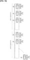
- the scheduled departure time of the vehicle 45 shown in Figure 15 has been calculated as 10:24. That is, the vehicle 45 departs before the vehicle 42 and after the vehicle 44. In this case, two stop locations of the vehicle 45 are conceivable. The two stop locations are between the vehicles 41 and 42, and behind the vehicle 44. However, because it is not possible to stop between the vehicles 41 and 42, as shown in Figure 15 , the stop location of the vehicle 45 is behind the vehicle 44. That is, in Figure 15 , a plurality of lines of vehicles are formed by the vehicles 40-44 that are already stopped in the stopping area 70 when the vehicle 45 arrives at the stopping area 70. More specifically, the vehicles 40 to 42 form the line of vehicles C1, and the vehicles 43-44 form the line of vehicles C2.
- the scheduled departure order of the vehicle 45 is before the vehicle 42 stopped at the end of the line of vehicles C1, and after the vehicle 44 stopped at the end of the line of vehicles C2.
- the stop location calculation unit 217 calculates the end of the line of vehicles C2 (i.e., behind the vehicle 44) as the stop location of the vehicle 45.
- the stopping area 70 can be used efficiently.
- the scheduled departure time of the vehicle 45 shown in Figure 16 has been calculated as 10:30.
- the stop location of the vehicle 45 may be behind the vehicle 42 or behind the vehicle 44. That is, the lines of vehicles C1 and C2 in Figure 16 are formed in the same way as in Figure 15 .
- the scheduled departure order of the vehicle 45 is after the respective scheduled departure order of the vehicles (vehicles 42, 44) stopped at the end of a plurality of lines of vehicles (lines of vehicles C1 and C2).
- the stop location calculation unit 217 calculates the end of one of the lines of vehicles (i.e., behind the vehicle 42, or behind the vehicle 44) as the stop location of the vehicle 45.
- the stopping area 70 can be used efficiently.
- the scheduled departure time of the vehicle 45 shown in Figure 17 has been calculated as 10:14.
- two stop locations of the vehicle 45 are conceivable.
- the two stop locations are between the vehicle 40 and 41, and between the vehicles 43 and 44.
- the stop location calculation unit 217 calculates a position separated from the lines of vehicles C1 and C2 by a prescribed distance as the stop location of the vehicle 45, and sets the calculated stop location as the lead position of a new line of vehicles C3. That is, the lines of vehicles C1 and C2 are formed in Figure 17 in the same manner as in Figures 15 and 16 .
- the scheduled departure of the vehicle 45 is before the respective scheduled departure of the vehicles (the vehicles 42 and 44) stopped at the end of a plurality of lines of vehicles (lines of vehicles C1 and C2).
- the stop location calculation unit 217 calculates a position separated from the plurality of lines of vehicles by a prescribed distance as the stop location of the vehicle 45, and sets the calculated stop location as the lead position of a new line of vehicles.
- the stopping area 70 can be used efficiently.
- the processing circuits include programmed processing devices, such as processing devices including electronic circuits.
- the processing circuits also include such devices as application-specific integrated circuits (ASIC) and electronic components arranged to execute the described functions.
- ASIC application-specific integrated circuits
- the departure time calculation unit 216 may acquire the number of users that deboard, or information pertaining to the users' luggage, to calculate the scheduled departure order based on the acquired number of people or the information pertaining to luggage.
- the stopping area 70 can be used efficiently even during deboarding. For example, by adding the time required for the user to deboard to the arrival time of the vehicle, the scheduled departure time can be calculated for the case of deboarding. Like the time required for boarding, the time required for deboarding increases as the number of people deboarding increases. Deboarding also requires more time as the amount of luggage, such as suitcases, increases, since removal of the luggage takes time. Deboarding also takes longer for a user using a wheelchair.
- the controller 20 acquires the number of users that deboard, or information pertaining to the luggage of deboarding users, included in the user-side information.
- the controller 20 calculates the times required for boarding and deboarding based on the acquired number of people or information pertaining to luggage.
- the controller 20 calculates the scheduled departure order based on the arrival times of the stop-scheduled vehicles and the times required for boarding and deboarding.
- the stop location calculation unit 217 may calculate the stop locations in the following manner. That is, the stop location calculation unit 217 may calculate the stop location of the vehicle whose stop location is behind, such that the distance (inter-vehicular distance) between the vehicle whose stop location is in front and the vehicle whose stop location is behind becomes small.
- the distance inter-vehicular distance
- the arrival time of the vehicle 40 is 10:00 and the arrival time of the vehicle 41 is 10:05. Further, the scheduled departure time of the vehicle 40 is 10:05, and the scheduled departure time of the vehicle 41 is 10:10. That is, the scheduled departure order is in the order of the vehicle 40 and the vehicle 41. Since the scheduled departure order of the vehicle 41 is after the scheduled departure order of the vehicle 40, the stop location calculation unit 217 calculates the stop location such that the stop location of the vehicle 41 is behind the vehicle 40. In Figure 18 , of two vehicles (vehicles 40 and 41) whose stop locations are one behind the other, the vehicle 40 whose stop location is in front arrives at the stopping area 70 before the vehicle 41 whose stop location is behind.
- the stop location calculation unit 217 may calculate the stop location (position P2) of the vehicle 41 whose stop location is behind, such that the distance (distance L1) between the vehicle 40 whose stop location is in front and the vehicle 41 whose stop location is behind becomes small. The reason for doing so is because it is known that the vehicle 40 will depart before the vehicle 41.
- the degree to which the distance is reduced is not particularly limited and may be smaller than a distance in which the rear door, or the like, as described in Figure 4 , is taken into consideration.
- the vehicle 41 may move forward to reduce the interval after checking, with a camera, or the like, that the user 50 has boarded the vehicle 40 in front. That the distance may be smaller means smaller compared with the case in which the vehicle 40 arrives at the stopping area 70 after the vehicle 41.
Landscapes
- Engineering & Computer Science (AREA)
- Business, Economics & Management (AREA)
- General Physics & Mathematics (AREA)
- Physics & Mathematics (AREA)
- Tourism & Hospitality (AREA)
- Human Resources & Organizations (AREA)
- Strategic Management (AREA)
- Economics (AREA)
- Entrepreneurship & Innovation (AREA)
- Theoretical Computer Science (AREA)
- General Business, Economics & Management (AREA)
- Marketing (AREA)
- Quality & Reliability (AREA)
- Development Economics (AREA)
- Operations Research (AREA)
- Remote Sensing (AREA)
- Radar, Positioning & Navigation (AREA)
- Mechanical Engineering (AREA)
- Automation & Control Theory (AREA)
- Game Theory and Decision Science (AREA)
- Transportation (AREA)
- Educational Administration (AREA)
- Human Computer Interaction (AREA)
- Health & Medical Sciences (AREA)
- General Health & Medical Sciences (AREA)
- Primary Health Care (AREA)
- Traffic Control Systems (AREA)
- Management, Administration, Business Operations System, And Electronic Commerce (AREA)
- Control Of Position, Course, Altitude, Or Attitude Of Moving Bodies (AREA)
- Train Traffic Observation, Control, And Security (AREA)
Description
- The present invention relates to a vehicle stop location control method, a vehicle stop location control device, and a vehicle stop location control system.
- An invention that detects a parking space and assists a vehicle to park in the detected parking space is known from the prior art (Patent Document 1). In the method disclosed in
Patent Document 1, obstacles in the parking space are detected, and a parking position is determined such that the detected obstacles will not hinder the boarding and deboarding of passengers and the opening/closing of the trunk. - The Patent Document 2 (see below) discloses a stop location control method using a controller for controlling stop locations of a plurality of vehicles that stop in a stopping area for allowing users to board and deboard, comprising the following steps performed by the controller:
- acquiring position information from the vehicles,
- acquiringuser-side information including position information of the users who use the vehicles or reservation information pertaining to the vehicles reserved by the users,
- extracting stop-scheduled vehicles, which are scheduled to stop in the stopping area from among the vehicles,
- calculating arrival times when the stop-scheduled vehicles will arrive at the stopping area based on the user-side information of the users who use the stop-scheduled vehicles, or based on position information of the stop-scheduled vehicles,
- calculating a scheduled departure order indicating an order in which the stop-scheduled vehicles will depart the stopping area after having stopped in the stopping area,
- calculating stop locations of the stop-scheduled vehicles, and
- transmitting information indicating the stop locations to the stop-scheduled vehicles.
- The Patent Document 3 (see below) discloses a network computing system for maximizing throughput for a common rendezvous location by determining estimated times of arrival to the common rendezvous location for matched users and/or the transport providers.
- The Patent Document 4 (see below) discloses a system for letting a parked car leave from the parking lot through autonomous driving. The parked cars are arranged in the order of times at which the parking cars are to leave.
- The Patent Document 5 (see below) discloses a device for assisting parking. The device detects obstacles around the parking lot at which the vehicle is to park.
- The Patent Document 6 (see below) discloses control of an autonomous vehicle to respond to queuing behaviors at pickup or drop-off locations. It is determined whether or not a queue for picking up and dropping off exists, and whether to join the queue. The vehicle is controlled to join the queue based on the determination.
-
- Patent Document 1:
JP 2009-190560 A - Patent Document 2:
JP 2015 - 176468 A - Patent Document 3:
WO 2019/ 113426 A1 - Patent Document 4:
JP 2015 - 219811 A - Patent Document 5:
JP 2009 - 190560 A - Patent Document 6:
WO 2020/ 076538 A1 - However, the method disclosed in
Patent Document 1 takes obstacles into consideration, but not efficiency, in a stopping area (where a plurality of vehicles can stop). Therefore, the method described inPatent Document 1 may not be able to utilize the stopping area efficiently. - In view of the problem described above, an object of the present invention is to provide a stop location control method, a stop location control device, and a stop location control system that can utilize a stopping area efficiently.
- In order to achieve the above mentioned object, provided is a stop location control method, a stop location control device and a stop location control system. The stop location control method according to one aspect of the present invention is a method using a controller for controlling stop locations of a plurality of vehicles that stop in a stopping area for allowing users to board and deboard, and comprising steps of:
- acquiring, by the controller, position information from the vehicles, acquiring, by the controller, user-side information including position information of the users who use the vehicles or reservation information pertaining to the vehicles reserved by the users,
- extracting, by the controller, stop-scheduled vehicles, which are scheduled to stop in the stopping area from among the vehicles,
- calculating, by the controller, arrival times when the stop-scheduled vehicles will arrive at the stopping area based on the user-side information of the users who use the stop-scheduled vehicles, or based on position information of the stop-scheduled vehicles,
- calculating, by the controller, a scheduled departure order indicating an order in which the stop-scheduled vehicles will depart the stopping area after having stopped in the stopping area,
- calculating, by the controller, stop locations of the stop-scheduled vehicles, and
- transmitting, by the controller, information indicating the stop locations to the stop-scheduled vehicles,
- characterised in that
- the calculation of the stop locations of the stop-scheduled vehicles is performed based on the scheduled departure order,
- of two stop-scheduled vehicles that occupy different positions in the order of departure, the stop-scheduled vehicle which is earlier in the scheduled order of departure is defined as a first stop-scheduled vehicle, and the stop-scheduled vehicle which is later in the scheduled order of departure is defined as a second stop-scheduled vehicle, and
- in the case that the first stop-scheduled vehicle arrives at the stopping area before the second stop-scheduled vehicle, calculating, by the controller, the stop location of the second stop-scheduled vehicle such that the distance between the first stop-scheduled vehicle and the second stop-scheduled vehicle becomes smaller compared with the case in which the first stop-scheduled vehicle arrives at the stopping area later than the second stop-scheduled vehicle.
- By means of the present invention, it becomes possible to utilize a stopping area efficiently.
-
-
Figure 1 is an overall schematic diagram of a stop location control system according to a first reference example which does not fall within the scope of the claims. -
Figure 2 is a functional block diagram of a controller, a vehicle, and a terminal device according to the first reference example which does not fall within the scope of the claims. -
Figure 3 is a diagram describing an example of the stop location control method according to the first reference example which does not fall within the scope of the claims. -
Figure 4 is a diagram describing another example of the stop location control method according to the first reference example which does not fall within the scope of the claims. -
Figure 5 is a diagram describing another example of the stop location control method according to the first reference example which does not fall within the scope of the claims. -
Figure 6 is a diagram describing another example of the stop location control method according to the first reference example which does not fall within the scope of the claims. -
Figure 7 is a diagram describing another example of the stop location control method according to the first reference example which does not fall within the scope of the claims. -
Figure 8 is a diagram describing movement of the stop location. -
Figure 9 is a flowchart describing an operation example of a controller according to the first reference example which does not fall within the scope of the claims. -
Figure 10 is a flowchart describing an operation example of the controller according to the first reference example which does not fall within the scope of the claims. -
Figure 11 is a flowchart describing an operation example of a vehicle according to the first reference example which does not fall within the scope of the claims. -
Figure 12 is a flowchart describing an operation example of the controller according to the first reference example which does not fall within the scope of the claims. -
Figure 13 is a flowchart describing an operation example of the vehicle according to the first reference example which does not fall within the scope of the claims. -
Figure 14 is a diagram describing one example of the stop location control method according to a first embodiment which does not fall within the scope of the claims. -
Figure 15 is a diagram describing another example of the stop location control method according to the first embodiment which does not fall within the scope of the claims. -
Figure 16 is a diagram describing another example of the stop location control method according to the first embodiment which does not fall within the scope of the claims. -
Figure 17 is a diagram describing another example of the stop location control method according to the first embodiment which does not fall within the scope of the claims. -
Figure 18 is a diagram describing one example of the stop location control method according to another embodiment corresponding to the claimed subject-matter. - A first reference example and a first embodiment, which do not fall within the scope of the claims, as well as another embodiment, corresponding to the claimed subject-matter are described below with reference to the figures. In the descriptions of the figures, identical parts have been assigned the same reference numerals, and their descriptions have been omitted.
- A configuration example of a stop
location control system 10 according to a first reference example will be described with reference toFigures 1-2 . The stoplocation control system 10 according to the first reference example dispatches a vehicle when a dispatch request from a user is received and calculates a stop location of the vehicle in a stopping area. - As shown in
Figure 1 , the stoplocation control system 10 includes acontroller 20, acommunication network 30,vehicles 40 to 42, a user 50, aterminal device 60 in the possession of the user 50, a user 51, and aterminal device 61 in the possession of the user 51. InFigure 1 , there are three vehicles, but no limitation is implied thereby. The stoplocation control system 10 may include four or more vehicles. Moreover, inFigure 1 , there are two users, but there are numerous users who are not shown. The numerous users who are not shown, like the users 50 and 51, also possess terminal devices. - The controller 20 (stop location control device) communicates with the
vehicles 40 to 42 and theterminal devices 60 to 61 via thecommunication network 30. Thecontroller 20 comprises a CPU (Central Processing Unit) 21, amemory 22, a communication I/F 23, and astorage 24, and these constituent elements are electrically connected via a bus, etc., not shown in the figure. Although the installation location of thecontroller 20 is not particularly limited, thecontroller 20 is installed, for example, in a business that operates thevehicles 40 to 42. - The
CPU 21 loads various programs stored in thestorage 24, etc., into thememory 22, and executes various instructions contained in the programs. Thememory 22 is a storage medium such as a ROM (Read Only Memory), RAM (Random Access Memory), etc. Thestorage 24 is a storage medium such as an HDD (Hard Disk Drive). Some (or all) of the stoplocation control system 10, including the functions of thecontroller 20, described below, may be provided by means of an application (Software as a Service (SaaS), etc.) located on thecommunication network 30. Thecontroller 20 may be a server. - The communication I/
F 23 is implemented as hardware, such as a network adapter, various types of communication software, or a combination thereof, and is configured to realize wired or wireless communication via thecommunication network 30, etc. - The
communication network 30 may be configured by a wireless and/or wired method, and thecommunication network 30 may include the Internet. In the first reference example, thecontroller 20, thevehicles 40 to 42, and theterminal devices 60 to 61 are connected to thecommunication network 30 by means of a wireless communication method. - The
vehicles 40 to 42 may be vehicles with a driver, or autonomous driving vehicles without a driver. In the first reference example, thevehicles 40 to 42 are described as autonomous driving vehicles without a driver. Thevehicles 40 to 42 are, for example, taxis, although the vehicles are not limited to taxis. - If the use of private cars as taxis is permitted by law (and even if it is not permitted by current law, but will be permitted in the future after a revision of the law), the
vehicles 40 to 42 may be private cars. - The user 50 requests (reserves) a vehicle using the
terminal device 60. A vehicle dispatch application (hereinafter referred to simply as a vehicle dispatch app) used for reserving vehicles is installed in theterminal device 60, and the user 50 requests a vehicle using the vehicle dispatch app. The user 51 also requests a vehicle using theterminal device 61. This type of vehicle request may be referred to as a vehicle dispatch request. - Next, with reference to
Figure 2 , details of thecontroller 20, thevehicle 40, and theterminal device 60 will be described. Although thevehicles terminal device 61 have been omitted fromFigure 2 , thevehicles vehicle 40, and theterminal device 61 has the same configuration as theterminal device 60. - The
terminal device 60 comprises a communication I/F 601 and avehicle dispatch app 602. The communication I/F 601 has the same configuration as the communication I/F 23 and communicates with thecontroller 20 via thecommunication network 30. Theterminal device 60 is, for example, a smartphone, a tablet, or the like. Theterminal device 60 may also be a wearable device. The terminal device 61 (not shown) includes a vehicle dispatch app 603 (not shown). - The
vehicle dispatch app 602 is used for requesting a vehicle, as described above. Thevehicle dispatch app 602 functions as a user interface when the user 50 requests a vehicle. Thevehicle dispatch app 602 is realized by the CPU provided in theterminal device 60 reading and executing a dedicated application program from a storage provided in theterminal device 60. When the user 50 requests a vehicle, the user 50 inputs a desired boarding location, boarding time, deboarding location, etc., into thevehicle dispatch app 602 to request the vehicle. Thevehicle dispatch app 602 transmits a dispatch request to thecontroller 20 in accordance with the input from the user 50. Further, theterminal device 60 displays, on a display provided in theterminal device 60, various types of information (dispatch request receipt, scheduled arrival time, scheduled travel route, etc.) included in the signal returned from thecontroller 20 in response to the dispatch request. However, the method of realizing thevehicle dispatch app 602 is not limited in this way. For example, theterminal device 60 may access a server that provides the functions of thevehicle dispatch app 602, receive the functions provided, and display the results of executing the functions transmitted from the server in a browser. - Further, the information input to the
vehicle dispatch app 602 by the user 50 includes the number of people who will board, the presence/absence of luggage, the presence/absence of a wheelchair, and the like. The information pertaining to luggage includes the number of pieces and the size of the luggage. - As shown in the block diagram of
Figure 2 , theCPU 21 of thecontroller 20 is provided with, as examples of a plurality of functions, a vehicledispatch acceptance unit 211, anassignment unit 212, aroute calculation unit 213, an arrivaltime calculation unit 214, anextraction unit 215, a departuretime calculation unit 216, and a stoplocation calculation unit 217. As shown in the block diagram ofFigure 2 , auser database 242 is stored in thestorage 24 of thecontroller 20. - The vehicle
dispatch acceptance unit 211 accepts a request from the user 50 via theterminal device 60. Further, the vehicledispatch acceptance unit 211 has the function of notifying theterminal device 60 of the acceptance of the request from the user 50, as well as of the scheduled arrival time to the boarding location, the scheduled travel route to the boarding location, etc. Further, the vehicledispatch acceptance unit 211 accepts a request from the user 51 via theterminal device 61. - The
assignment unit 212 assigns a suitable vehicle from among the plurality ofvehicles 40 to 42 based on the accepted dispatch request. For example, for reasons of efficiency, theassignment unit 212 can assign theunoccupied vehicle 40 that, of the plurality ofvehicles 40 to 42, is closest to the boarding location desired by the user 50. Further, if the user 50 has specified a vehicle type, theassignment unit 212 assigns the specified vehicle type. GPS receivers are installed in thevehicles 40 to 42, and the location information of thevehicles 40 to 42 is transmitted to thecontroller 20 at any given time. - The
route calculation unit 213 calculates a route from the current location of thevehicle 40 to the boarding location desired by the user 50 and sends an instruction to thevehicle 40 to travel to the boarding location desired by the user 50 via the calculated route. The route calculated by theroute calculation unit 213 is, for example, the route via which the boarding location desired by the user 50 can be reached from the current location of thevehicle 40 in the shortest amount of time. - The arrival
time calculation unit 214 calculates the time at which thevehicle 40 will arrive at the boarding location desired by the user 50. In other words, the arrivaltime calculation unit 214 calculates the time required to travel to the boarding location desired by the user 50 via the route calculated by theroute calculation unit 213. - The
extraction unit 215 extracts a vehicle scheduled to stop at a stopping area for boarding and deboarding the user 50 from among thevehicles 40 to 42. Theextraction unit 215 refers to the reservation information of the user 50, and if the boarding location related to the dispatch request is set in the stopping area, theextraction unit 215 extracts the assigned vehicle as the vehicle scheduled to stop in the stopping area. In the following, a vehicle scheduled to stop in the stopping area may be referred to as a stop-scheduled vehicle. - The departure
time calculation unit 216 refers to the reservation information of the users, theuser database 242, etc., to calculate the times (scheduled departure times) that vehicles stopped in the stopping area will depart the stopping area. The departuretime calculation unit 216 calculates the time required for boarding and deboarding, from the time that the user started to board and deboard until the time that the boarding and deboarding ended. The time required for boarding and deboarding is classified into the time required for boarding and the time required for deboarding. In the case that a user boards the vehicle in the stopping area, the scheduled departure time is calculated by adding the time required for boarding to the time at which the user arrives at the stopping area. The time required for boarding will be described. In general, boarding takes more time as the number of people boarding increases. Further, the greater the amount of luggage, such as suitcases, the longer it takes time to load the luggage, which increases the time required for boarding. Further, boarding takes longer when it is raining, as opposed to when it is sunny, since more movements are involved, such as closing an umbrella. Boarding also takes longer for a user using a wheelchair. Boarding also takes longer for a user using the vehicle for the first time, as opposed to a user who uses the vehicle frequently. The time required for deboarding will be described further below. - Information concerning the number of people boarding, luggage, and wheelchairs, etc., can be obtained by referring to the user reservation information. Vehicle usage history is obtained by referring to the
user database 242. Weather information is obtained by referring to the Internet. The usage history stored in theuser database 242 includes the user's movement speed, trend information regarding meeting with reserved vehicles, and the like. - In addition to the scheduled departure times, the departure
time calculation unit 216 calculates a scheduled departure order that indicates the order in which vehicles will depart the stopping area after having stopped in the stopping area. The scheduled departure order is obtained by arranging the scheduled departure times in chronological order. - The stop
location calculation unit 217 calculates the stop locations of vehicles in the stopping area based on the scheduled departure order calculated by the departuretime calculation unit 216. - The
vehicle 40 is equipped with a communication I/F 401 and a vehicle ECU (Electronic Control Unit) 402. The communication I/F 401 has the same configuration as the communication I/F 23 and the communication I/F 601, and communicates with thecontroller 20 via thecommunication network 30. Thevehicle ECU 402 is a computer for controlling thevehicle 40. Thevehicle ECU 402 controls various actuators (brake actuator, accelerator pedal actuator, steering actuator, etc.) based on the commands from thecontroller 20. - In the first reference example, a stop means a temporary stop to allow the user to board and deboard a vehicle.
- Next, an example of the stop location control method when there is one stop-scheduled vehicle will be described with reference to
Figure 3 . - The scenario shown in
Figure 3 is one scenario in which the user 50 has reserved a vehicle using thevehicle dispatch app 602 and is waiting for the vehicle. It is assumed that the reservation time specified by the user 50 is 10:00, and that the boarding location specified by the user 50 is stoppingarea 70. The stoppingarea 70 is a boarding and deboarding location in which a plurality of vehicles can stop, such as a roundabout in front of a train station, a taxi zone at an airport, etc. - In
Figure 3 , the vehicle assigned to the user 50 is thevehicle 40. Theextraction unit 215 refers to the reservation information of the user 50 to extract thevehicle 40 scheduled to stop in the stoppingarea 70. Since the reservation information of the user 50 includes the boarding location, theextraction unit 215 can refer to the reservation information of the user 50 to extract a vehicle scheduled to stop in any stopping area (the stoppingarea 70 in the example shown inFigure 3 ). The extraction timing is not particularly limited. Theextraction unit 215 may extract thevehicle 40 scheduled to stop in the stoppingarea 70 when theassignment unit 212 assigns a vehicle. Theextraction unit 215 may also extract thevehicle 40 as a vehicle scheduled to stop in the stoppingarea 70 before thevehicle 40 arrives at the stoppingarea 70. Before thevehicle 40 arrives at the stoppingarea 70 is, for example, when thevehicle 40 is traveling toward the stoppingarea 70. - In
Figure 3 , it is assumed that only thevehicle 40 is extracted as a vehicle scheduled to stop in the stoppingarea 70. Further, it is assumed that are no other vehicles in the stoppingarea 70 besides thevehicle 40. It is assumed that thevehicle 40 was extracted before arriving at the stoppingarea 70. - Upon receiving the signal indicating that
vehicle 40 has been extracted, the departuretime calculation unit 216 calculates the scheduled departure time at which thevehicle 40 will depart the stoppingarea 70 after having stopped in the stoppingarea 70. The scheduled departure time is calculated by adding the time required for boarding to the time at which the user 50 arrives at the stoppingarea 70. - There is a plurality of methods for acquiring or estimating the time at which the user 50 will arrive at the stopping
area 70. For example, the departuretime calculation unit 216 may regard 10:00, which is the reservation time of the user 50, as the time at which the user 50 will arrive at the stoppingarea 70. This is because it is generally assumed that the user will arrive at the stoppingarea 70 at his or her specified reserved time. Alternatively, the departuretime calculation unit 216 may acquire the location information of theterminal device 60 in possession of the user 50 in order to estimate, based on the acquired location information, the time at which the user 50 will arrive at the stoppingarea 70. The location information of theterminal device 60 in possession of the user 50 can be regarded as the location information of the user 50. The obtained location information of the user 50 and the walking speed (movement speed) of the user 50 can be combined in order to obtain the time at which the user 50 will arrive at the stoppingarea 70. Since the walking speed of the user 50 is stored in theuser database 242, the departuretime calculation unit 216 can refer to theuser database 242 to acquire the walking speed of the user 50. - The departure
time calculation unit 216 may also regard the time at which thevehicle 40 is to arrive at the stopping area 70 (arrival time) as the time at which the user 50 arrives at the stoppingarea 70. This is because the arrival time is calculated based on the reservation time of the user 50. As described above, the arrival time is calculated by the arrivaltime calculation unit 214. InFigure 3 , the arrival time was calculated as 10:00, and thevehicle 40 actually arrived at the stoppingarea 70 at 10:00. - In
Figure 3 , the departuretime calculation unit 216 estimated that the time at which the user 50 will arrive at the stoppingarea 70 is 10:00 (same as the reservation time). - The departure
time calculation unit 216 refers to the reservation information of the user 50, theuser database 242, etc., in order to calculate the time required for the user 50 to board. As described above, the time required for boarding is calculated based on such information as the number of people boarding, the amount of luggage, the presence of a wheelchair, etc. InFigure 3 , the time required for boarding is calculated to be 5 minutes. Therefore, by adding 5 minutes to 10:00, which is the arrival time of the user 50, the scheduled departure time is 10:05. The departuretime calculation unit 216 also calculates the scheduled departure order. InFigure 3 , because there is one vehicle (only vehicle 40) scheduled to stop in the stoppingarea 70, the departure order of thevehicle 40 is first. - The stop
location calculation unit 217 receives a signal indicating the scheduled departure order and calculates the stop location of thevehicle 40 based on the received signal. Sincevehicle 40 is scheduled to depart first and there are no other vehicles, the stoplocation calculation unit 217 calculates a position P1 at the far end of the stoppingarea 70 as the stop location of thevehicle 40. Thecontroller 20 transmits information indicating the stop location to thevehicle 40. Information indicating the stop location may be coordinate information (world coordinate system) or image information. Alternatively, the information indicating the stop location may be the coordinate position on an X axis, where the X axis is defined as the direction of travel of the vehicle. Thevehicle 40 stops at the far end position P1 based on the received information. - Next, an example of the stop location control method when there are two stop-scheduled vehicles will be described with reference to
Figure 4 . - The user 50 in
Figure 4 is same as the one inFigure 3 . In other words, the user 50 has used the vehicle dispatch app to reserve a vehicle and is waiting for the vehicle. The reservation time specified by the user 50 is 10:00, and the boarding location specified by the user 50 is the stoppingarea 70. -
Figure 4 differs fromFigure 3 in the presence of the user 51. InFigure 4 , the user 51, like the user 50, has also used the vehicle dispatch app to reserve a vehicle and is waiting for the vehicle. The reservation time specified by the user 51 is 10:05, and the boarding location specified by the user 51 is the stoppingarea 70. - In
Figure 4 , the vehicle assigned to the user 50 is thevehicle 40, and the vehicle assigned to the user 51 is thevehicle 41. Also, no other vehicles besides thevehicles area 70. - Upon receiving a signal indicating that the
vehicles time calculation unit 216 calculates the scheduled departure times at which thevehicles area 70 after having stopped in the stoppingarea 70. The method of calculating the scheduled departure times is the same as that used in relation toFigure 3 . Some users may arrive at the stoppingarea 70 later than the reservation time or arrive at the stoppingarea 70 earlier than the reservation time. That is, calculating the scheduled departure order by taking only the reservation time into consideration may result in poor accuracy. Thus, in addition to the reservation time, the location information of the users 50 and 51 may also be considered. It is possible to accurately calculate the scheduled departure order, described further below. The departuretime calculation unit 216 may also refer to the usage history (user database 242) of the users 50 and 51 to acquire the movement speeds of the users 50 and 51, or trend information regarding meeting thevehicles vehicles time calculation unit 216 may calculate the scheduled departure order based on the acquired movement speeds or trend information. In this way, it is possible to calculate the scheduled departure order accurately. - In
Figure 4 , the departuretime calculation unit 216 has estimated that the time at which the user 50 will arrive at the stoppingarea 70 is 10:00 (the same as the reservation time). Further, the departuretime calculation unit 216 has estimated that the time at which the user 51 will arrive at the stoppingarea 70 is 10:05 (the same as the reservation time). - The departure
time calculation unit 216 refers to the reservation information of the users 50 and 51, theuser database 242, etc., to calculate the times required for the users 50 and 51 to board. The method of calculating the time required for boarding is the same as that used in relation toFigure 3 . InFigure 4 , the time required for the user 50 to board is calculated to be 5 minutes. Therefore, by adding 5 minutes to 10:00, the scheduled departure time for thevehicle 40 is 10:05. The time required for the user 51 to board is also calculated to be 5 minutes. Thus, by adding 5 minutes to 10:05, the scheduled departure time of thevehicle 41 is 10:10. - The scheduled departure times are arranged in chronological order by the departure
time calculation unit 216 in order to calculate the scheduled departure order. InFigure 4 , thevehicle 40 is scheduled to depart first, and thevehicle 41 is scheduled to depart second. That is, the scheduled departure order isvehicle 40, thenvehicle 41. InFigure 4 , the vehicles will depart in the order of their arrival at the stoppingarea 70. - The stop
location calculation unit 217 receives a signal indicating the scheduled departure order and calculates the stop location of thevehicle vehicle 40 is first and there are no other vehicles, the stoplocation calculation unit 217 calculates the far end position P1 of the stoppingarea 70 as the stop location of thevehicle 40. - Further, since the scheduled departure order of the
vehicle 41 is second, the stoplocation calculation unit 217 calculates the stop location such that the stop location of thevehicle 41 is behind thevehicle 40. For example, the stoplocation calculation unit 217 can calculate a position P2, which is separated from thevehicle 40 by a distance L1, as the stop location. The distance L1 may be any distance that allows thevehicle 41 to depart while avoiding thevehicle 40 and is calculated using the dimensions of thevehicle 41. The dimensions of thevehicle 41 include the total length of thevehicle 41, the turning radius of thevehicle 41, the center-to-center distance between the front and rear wheels of thevehicle 41, etc. Further, the distance L1 may be a distance that allows use of a rear opening/closing mechanism of thevehicle 40. A rear opening/closing mechanism of the vehicle includes the trunk, a rear door, etc. The distance L1 may be any distance that allows the user 50 to safely open the rear door of thevehicle 40 and loads luggage. - The
controller 20 transmits information indicating the stop locations to thevehicles vehicle 40 stops at the far end position P1 based on the received information. Thevehicle 41 stops at the position P2 based on the received information. - In
Figure 4 , the scheduled departure order is calculated by adding the times required for boarding to the reservation times of the users 50 and 51, but no limitation is implied thereby. The scheduled departure order may be calculated by adding the times required for boarding to the times at which thevehicles - Next, another example of the stop location control method when there are two stop-scheduled vehicles will be described with reference to
Figure 5 . - In the example shown in
Figure 5 , unlikeFigure 4 , the order of arrival at the stoppingarea 70 and the order of departure differ. That is, inFigure 5 , thevehicle 40 arrives at the stoppingarea 70 before thevehicle 41, but thevehicle 40 departs the stoppingarea 70 after thevehicle 41 departs. Descriptions equivalent to those inFigure 4 will be omitted. - Upon receiving a signal indicating that the
vehicles time calculation unit 216 calculates the scheduled departure times at which thevehicles area 70 after having stopped in the stoppingarea 70. - The departure
time calculation unit 216 refers to the reservation information of the users 50 and 51, theuser database 242, etc., to calculate the times required for the users 50 and 51 to board. InFigure 5 , the time required for the user 50 to board is calculated as 10 minutes. Therefore, by adding 10 minutes to 10:00, the scheduled departure time for thevehicle 40 is 10:10. Also, the time required for the user 51 to board is calculated to be 3 minutes. Therefore, by adding 3 minutes to 10:05, the scheduled departure time for thevehicle 41 is 10:08. Thus, inFigure 5 , thevehicle 40 departs the stoppingarea 70 after thevehicle 41 departs. - The scheduled departure times are arranged in chronological order by the departure
time calculation unit 216 in order to calculate the scheduled departure order. InFigure 5 , thevehicle 40 is scheduled to depart second, and thevehicle 41 is scheduled to depart first. That is, the scheduled departure order isvehicle 41, thenvehicle 40. - The stop
location calculation unit 217 receives a signal indicating the scheduled departure order and calculates the stop locations of thevehicles vehicle 40 is second, and thevehicle 41 has not yet arrived. Thus, the stoplocation calculation unit 217 secures a space for thevehicle 41, arriving later, in which to stop, and calculates the stop location of thevehicle 40. Specifically, as shown inFigure 5 , the stoplocation calculation unit 217 calculates a position P2, which is separated from the far end position P1 by a distance L3, as the stop location of thevehicle 40. The distance L3 is the distance obtained by adding the distance L1 to a distance L2 equal to the total length of thevehicle 41. The reason the far end position P1 is used as a reference is because thevehicle 41 is scheduled to depart first. - Since the
vehicle 41 is scheduled to depart first, the stoplocation calculation unit 217 calculates the far end position P1 of the stoppingarea 70 as the stop location of thevehicle 41. - The
controller 20 transmits information indicating the stop locations to thevehicles vehicle 40 stops at the position P2, as shown inFigure 5 . Thevehicle 41 arrives at the stoppingarea 70 after thevehicle 40 has stopped in the position P2. Based on the received information, thevehicle 41 stops at the far end position P1. - Thus, according to the first reference example, the stop locations are calculated to be in the order of departure from the stopping
area 70, instead of the order of arrival to the stoppingarea 70. As a result, by means of the first reference example, the stoppingarea 70 can be efficiently utilized, as opposed to the case of the conventional technology in which the vehicles make uncoordinated stops. - In
Figure 5 , information pertaining to the total length of thevehicle 41 is necessary to calculate the position P2, and the stoplocation calculation unit 217 can refer to a database, or the like to acquire the information regarding the total length of thevehicle 41. Besides the vehicle total length, other information regarding the vehicle body can also be acquired by the stoplocation calculation unit 217. The stoplocation calculation unit 217 can also acquire, in addition to information related to thevehicle 41, information pertaining to other vehicles that may pertain to the first reference example. - Next, another example of the stop location control method will be described with reference to
Figure 6 . - The scenario shown in
Figure 6 is a one in which thevehicle 40 has already stopped at the far end position P1 when avehicle 44 arrives at the stoppingarea 70. Also, thevehicles area 70 when thevehicle 44 arrives at the stoppingarea 70, but thevehicles vehicle 44. - In
Figure 6 , the scheduled departure order isvehicle 40,vehicle 41,vehicle 42,vehicle 43, andvehicle 44. The stoplocation calculation unit 217 receives a signal indicating the scheduled departure order and calculates the stop location of thevehicle 44 based on the received signal. Because thevehicles area 70, the stoplocation calculation unit 217 calculates the stop location of thevehicle 44 such that thevehicles vehicle 44. For example, as shown inFigure 6 , the stoplocation calculation unit 217 can calculate a position P3, which is separated from thevehicle 40 by a distance L10, as the stop location of thevehicle 44. InFigure 6 , thevehicle 40 is a vehicle that serves as a reference (hereinafter referred to as the reference vehicle) when the stop location is calculated. - The distance L10 is the distance obtained by adding distances L1, L4, L5, L6, L7, L8, and L9. The distance L5 is the total length of the
vehicle 41. The distance L6 is the total length of thevehicle 42. The distance L9 is the total length of thevehicle 43. The distance L4 is a distance with which thevehicle 42 can depart while avoiding thevehicle 41. The distance L6 is a distance with which thevehicle 43 can depart while avoiding thevehicle 42. The distance L8 is a distance with which thevehicle 44 can depart while avoiding thevehicle 43. - Thus, the stop
location calculation unit 217 calculates a location, which is separated from the reference vehicle by the distance L10, as the stop location. Thecontroller 20 transmits information indicating the stop location to thevehicle 44. Based on the received information, thevehicle 44 stops at the position P3, as shown inFigure 6 . Thevehicles area 70 later, will thus be able to stop in the order of departure. In this way, in accordance with the first reference example, the stop locations are calculated to be their order of departure from the stoppingarea 70, instead of their order of arrival to the stoppingarea 70. Thus, the stoppingarea 70 can be utilized efficiently. - Next, another example of the stop location control method will be described with reference to
Figure 7 . - The scenario shown in
Figure 7 is one in which by the time that thevehicle 44 arrives at the stoppingarea 70, none of the other vehicles have yet arrived at the stoppingarea 70. That is, compared to the scenario ofFigure 6 , inFigure 7 , the vehicle 40 (the reference vehicle) has not yet arrived at the stoppingarea 70. - As in
Figure 6 , inFigure 7 , the scheduled departure order is in the order of thevehicle 40, thevehicle 41, thevehicle 42, thevehicle 43, and thevehicle 44. Since thevehicles area 70, the stoplocation calculation unit 217 calculates the stop location of thevehicle 44 such that thevehicles vehicle 44. For example, the stoplocation calculation unit 217 sets the far end position P1 as a reference position for calculating the stop location. As shown inFigure 7 , the stoplocation calculation unit 217 can calculate the position P3, which is separated from the reference position (far end position P1) by a distance L11, as the stop location of thevehicle 44. - The distance L11 is the distance obtained by adding the distances L1, L2, L4, L5, L6, L7, L8, and L9. If a reference vehicle, such as that shown in
Figure 6 , is not present, the stoplocation calculation unit 217 can calculate the stop location using the far end position P1 as a reference. - The movement of the stop location will now be described with reference to
Figure 8 . - As shown in
Figure 8 , upon receiving a signal indicating that thevehicle 40, whose scheduled departure order is first, has departed, the stoplocation calculation unit 217 moves the stop locations of thevehicles 41 to 44 forward by the distance L3 (distance L1 + L2). Thevehicles 41 to 44 thus move forward by the distance L3. Thus, the stoppingarea 70 can be used efficiently. - An operation example of the
controller 20 will now be described with reference to the flowchart ofFigure 9 . - In Step S101, the vehicle
dispatch acceptance unit 211 accepts a user request via a terminal device in possession of the user. The process proceeds to Step S103, and, based on the accepted request, theassignment unit 212 assigns a suitable vehicle from among the plurality of vehicles. For example, if the user has specified the vehicle type, theassignment unit 212 assigns the specified vehicle type. Further, if the user has not specified the vehicle type, theassignment unit 212 can assign an unoccupied vehicle that is closest to the boarding location desired by the user. - The process proceeds to Step S105, and the
route calculation unit 213 calculates a route from the current location of the vehicle to the boarding location desired by the user and sends an instruction to the vehicle to travel to the boarding location desired by the user via the calculated route. The process proceeds to Step S107, and the arrivaltime calculation unit 214 calculates the time at which the vehicle will arrive at the boarding location desired by the user. - The process proceeds to Step S109, and the
extraction unit 215 refers to the reservation information of the user in order to extract the vehicle scheduled to stop in the stopping area. The process proceeds to Step S111, and upon receiving a signal indicating that the vehicle has been extracted, the departuretime calculation unit 216 calculates the scheduled departure time at which the vehicle will depart the stopping area after having stopped in the stopping area. As one example, the scheduled departure time is calculated by adding the time required for boarding to the time at which the user will arrive at the stopping area. In addition to the scheduled departure time, a scheduled departure order indicating the order in which vehicles will depart the stopping area after having stopped in the stopping area is calculated by the departuretime calculation unit 216. The scheduled departure order is obtained by arranging the scheduled departure times in chronological order. - The process proceeds to Step S113, in which the stop
location calculation unit 217 receives a signal indicating the scheduled departure order and, based on the received signal, calculates the stop location of the vehicle. The process proceeds to Step S115, and thecontroller 20 transmits information indicating the stop location to the vehicle. Based on the received information, the vehicle stops at the stop location. - An operation example of the stop
location calculation unit 217 will now be described with reference to the flowchart ofFigure 10 . The flowchart ofFigure 10 describes Step S113 ofFigure 9 in detail. - If the vehicle that arrived at the stopping area is scheduled to depart first (YES in Step S201), the process proceeds to Step S203, and the stop
location calculation unit 217 calculates the far end position of the stopping area as the stop location of the vehicle. More specifically, if, as shown inFigure 4 , thevehicle 40 that arrived at the stoppingarea 70 is scheduled to depart first, the stoplocation calculation unit 217 calculates the far end position P1 of the stoppingarea 70 as the stop location of thevehicle 40. - On the other hand, if the vehicle that arrived at the stopping area is not scheduled to depart first (NO in Step S201), the process proceeds to Step S205. If another vehicle that is scheduled to depart earlier has already stopped by the time the vehicle arrives at the stopping area (YES in Step S205), the process proceeds to Step S207. In Step S207, the stop
location calculation unit 217 sets the vehicle that has already stopped as the reference vehicle for calculating the stop location. More specifically, as shown inFigure 6 , the stoplocation calculation unit 217 sets thevehicle 40 that has already stopped in the stoppingarea 70 as the reference vehicle for calculating the stop location of thevehicle 44. The process proceeds to Step S209, in which the stoplocation calculation unit 217 acquires information in regard to theother vehicles 41 to 43 (total length, etc.) (refer toFigure 6 ). - The process proceeds to Step S211, and the stop
location calculation unit 217 calculates the distances L4, L6, and L8, so that thevehicles 41 to 43, which will arrive at the stoppingarea 70 later, will be able to stop in the order of departure (refer toFigure 6 ). The process proceeds to Step S213, and the stoplocation calculation unit 217 calculates the position P3, which is separated from the reference vehicle (the vehicle 40) by the distance L10, as the stop location of the vehicle 44 (refer toFigure 6 ). - If another vehicle that is earlier in the scheduled departure order has not stopped by the time that the vehicle arrives at the stopping area (NO in Step S205), the process proceeds to Step S215. In Step S215, the stop
location calculation unit 217 sets the far end position as the reference position for calculating the stop location. More specifically, as shown inFigure 7 , the stoplocation calculation unit 217 sets the far end position P1 as a reference position for calculating the stop location. The process proceeds to Step S217, in which the stoplocation calculation unit 217 acquires information in regard to theother vehicles 40 to 43 (the total length, etc.) (refer toFigure 7 ). - The process proceeds to Step S219, and the stop
location calculation unit 217 calculates the distances L1, L4, L6, and L8, so that thevehicles 40 to 43, which will arrive at the stoppingarea 70 later, will be able to stop in the order of departure (refer toFigure 7 ). The process proceeds to Step S221, and the stoplocation calculation unit 217 calculates the position P3, which is separated from the reference position (the far end position P1) by the distance L11, as the stop location of the vehicle 44 (refer toFigure 7 ). - An operation example of the vehicle side will now be described with reference to the flowchart of
Figure 11 . - In Step S301, the vehicle receives position information for stopping in the stopping area from the
controller 20. The time at which the vehicle receives the position information is not particularly limited, but, in the flowchart, the time at which the vehicle receives the position information is before the vehicle arrives at the stopping area. - If the vehicle has arrived at the stopping area (YES in Step S303) and the stop location is the far end position (YES in Step S305), the vehicle stops at the far end position (Step S313). On the other hand, if the stop location is neither the far end position (NO in Step S305) nor a position separated from the far end position by a prescribed distance (NO in Step S307), the vehicle detects a reference vehicle (Step S309). Step S309 means that the distance L10, shown in
Figure 6 , has been transmitted from thecontroller 20. That is, the stop location of the vehicle 44 (the position P3) is separated from the reference vehicle (the vehicle 40) by the distance L10. The reason that thevehicle 44 is to detect the reference vehicle (the vehicle 40) in Step S309 is to check whether the reference vehicle (the vehicle 40) has actually stopped. A camera, radar, etc., is used to detect the reference vehicle (the vehicle 40). - The process proceeds to Step S311, in which the
vehicle 44 stops at the position P3, which is separated from the reference vehicle (the vehicle 40) by the distance L10 (refer toFigure 6 ). - On the other hand, if the stop location is separated from the far end position by the prescribed distance (YES in Step S307), the
vehicle 44 stops at the position P3, which is separated from the far end position P1 by the distance L11 (refer toFigure 7 ). - An operation example of the
controller 20 and the vehicle will now be described with reference to the flowcharts ofFigures 12, 13 . - In Step S401 of
Figure 12 , thecontroller 20 determines whether the vehicle has departed the stopping area. Position information of the vehicle, position information of the user boarding the vehicle, etc., are used for this determination. Alternatively, thecontroller 20 may receive from the vehicle a signal indicating its departure to make this determination. - If the vehicle has departed the stopping area (YES in Step S401), the
controller 20 transmits a stop distance pertaining to the departed vehicle to other vehicles. More specifically, as shown inFigure 8 , thecontroller 20 transmits the distance L3 (distance L1+L2) to theother vehicles 41 to 44 that pertains to the departedvehicle 40. - In Step S501 of
Figure 13 , thevehicles 41 to 44 receive distance L3 from thecontroller 20. Thevehicles 41 to 44 detect whether the preceding vehicle (vehicle 40 with respect tovehicle 41; the same applies in the following). If the preceding vehicle has moved (YES in Step S503), thevehicles 41 to 44 move forward by the distance L3 (Step S505, refer toFigure 8 ). - As described above, the following actions and effects can be achieved by means of the stop
location control system 10 according to the first reference example. - The
extraction unit 215 extracts a plurality of thevehicles 40 and 41 (stop-scheduled vehicle), which are vehicles scheduled to stop in the stopping area 70 (refer toFigure 5 ). The departuretime calculation unit 216 calculates the scheduled departure order indicating the order in which thevehicles area 70 after having stopped in the stoppingarea 70, based on at least the reservation information pertaining to thevehicles vehicles area 70. In the example shown inFigure 5 , thevehicle 41 is scheduled to depart first, and thevehicle 40 is scheduled to depart second. The stoplocation calculation unit 217 receives a signal indicating the scheduled departure order and calculates the stop locations of thevehicles Figure 5 , the stop location of thevehicle 40 is calculated as the position P2. The stop location of thevehicle 41 is calculated as the far end position P1. Thus, since the stop locations are calculated in the order of departure from the stoppingarea 70, stoppingarea 70 can be used efficiently. - Further, as shown in
Figure 5 , the stop location (far end position P1) of thevehicle 41, which is earlier in the departure order, is calculated to be ahead of the stop location (position P2) of thevehicle 40, which is later in the scheduled departure order. Thus, since the stop locations are calculated in the order of departure from the stoppingarea 70, stoppingarea 70 can be used efficiently. - Further, when the users 50 and 51 board the
vehicles area 70, the departuretime calculation unit 216 may acquire the position information of the terminals (theterminal devices 60 and 61) in possession of the users 50 and 51. The departuretime calculation unit 216 may then calculate the scheduled departure order based on the acquired position information. Combining the position information of the users 50 and 51 and walking speeds (movement speeds) of the users 50 and 51 makes it possible to obtain the time at which the users 50 and 51 will arrive at the stoppingarea 70. Some users may arrive at the stoppingarea 70 after the reservation time or arrive at the stoppingarea 70 before the reservation time. By taking the position information of the users into consideration, the arrival times of the users can be calculated accurately. - Further, when the users 50 and 51 board the
vehicles area 70, the departuretime calculation unit 216 may refer to the usage history (the user database 242) of the users 50 and 51 to acquire the movement speeds of the users 50 and 51 or trend information in regard to meeting thevehicles vehicles time calculation unit 216 may calculate the scheduled departure order based on the acquired movement speeds or trend information. In this way, the scheduled departure order can be calculated accurately. - The stop
location calculation unit 217 may use a rear opening/closing mechanism (trunk, rear door) of thevehicles vehicles 40 and 41 (total length, turning radius, center-to-center distance between the front and rear wheels, etc.) to calculate the stop locations. As a result, the size of the parking space can be set in accordance with vehicle characteristics, and the stoppingarea 70 can be used efficiently. - The stop
location calculation unit 217 may determine whether there is areference vehicle 40 that has already stopped in the stoppingarea 70 by the time thevehicle 44 arrives at the stoppingarea 70. As shown inFigure 6 , if thereference vehicle 40 is already there and thevehicle 44 is earlier in the scheduled departure order, and theother vehicles 41 to 43, which are later in the scheduled departure order than thereference vehicle 40, have not yet arrived at the stoppingarea 70, the stoplocation calculation unit 217 may calculate the position P3, which is separated from thereference vehicle 40 by the distance L10, as the stop location of thevehicle 44, so that theother vehicles 41 to 43 will be able to stop. As a result, the stop locations are calculated in the order of departure from the stoppingarea 70, instead of the order of arrival at the stoppingarea 70. Thus, the stoppingarea 70 can be used efficiently. - Further, if other stop-scheduled vehicles, whose scheduled order of departure is between that of the stop-scheduled vehicle and the
reference vehicle 40, have not yet arrived at the stoppingarea 70, thecontroller 20 may calculate a position which is separated from thereference vehicle 40 by a prescribed distance as the stop location of the stop-scheduled vehicle, such that the other stop-scheduled vehicles will be able to stop. - If the vehicle 40 (first stop-scheduled vehicle), whose scheduled departure order is first, departs the stopping
area 70, as shown inFigure 8 , the stoplocation calculation unit 217 may move the stop location of the vehicle 42 (second stop-scheduled vehicle), whose scheduled departure order is second, forward. Further, the stoplocation calculation unit 217 may move the stop locations of thevehicles vehicle 42. Thus, the stoppingarea 70 can be used efficiently. - The
controller 20 controls the stop locations of a plurality of vehicles that stop in the stopping area to board and deboard users. Thecontroller 20 acquires position information from a plurality of vehicles. Thecontroller 20 acquires user-side information, including position information of the users that use the plurality of vehicles or reservation information pertaining to the vehicles reserved by the users. Thecontroller 20 extracts from among the plurality of vehicles stop-scheduled vehicles, which are vehicles that are scheduled to stop in the stopping area. Thecontroller 20 calculates the arrival times when the stop-scheduled vehicles will arrive at the stopping area based on at least the user-side information of the users who use the stop-scheduled vehicles, or on position information of the stop-scheduled vehicles. Thecontroller 20 calculates, based on the arrival times and times required for boarding and deboarding, a scheduled departure order indicating the order in which the stop-scheduled vehicles are to depart the stopping area after having stopped in the stopping area. Thecontroller 20 calculates the stop locations of the stop-scheduled vehicles based on the scheduled departure order. Thecontroller 20 transmits information indicating the stop locations to the stop-scheduled vehicles. The user-side information includes information pertaining to reservations and information stored in theuser database 242. - A first embodiment will be described next with reference to
Figures 14 to 17 . The first embodiment is different from the first reference example in that a line of vehicles is formed in the stoppingarea 70. The same reference numerals have been used for configurations that are equivalent to those of the first reference example, and their descriptions have been omitted. The following explanation emphasizes the differences.Reference numeral 70 has been omitted inFigures 14 to 17 . - The line of vehicles pertaining to the first embodiment will be described with reference to
Figure 14 . In the first embodiment, a row of vehicles are stopped in a line and face the same direction. As shown inFigure 14 , two lines of vehicles (lines of vehicles C1 and C2) are have formed in the stoppingarea 70. - The line of vehicles C1 includes the
vehicles 40 to 42. Thevehicles 40 to 42 are stopped in their order of departure from the stoppingarea 70. The line of vehicles C2 includes thevehicles vehicles area 70. InFigure 14 , since the scheduled departure time for thevehicle 43 is 10:10, it is desired that this vehicle stop between thevehicle 40 and thevehicle 41. However, depending on the user's reserved time, the extraction time by theextraction unit 215, etc., thevehicle 43 may not be able to stop between thevehicle 40 and thevehicle 41. One example of such a case is when thevehicle 40 and thevehicle 41 are stopped in the stoppingarea 70. In this case, the vehicles cannot stop in the order of departure in the line of vehicles C1. Thus, a new line of vehicles C2 is formed such that the scheduled order of departure for thevehicle 43 is first. The stop locations pertaining to the lines of the vehicles C1 and C2 are calculated by the stoplocation calculation unit 217. - Next, a case in which a
new vehicle 45 arrives at the stoppingarea 70 after the lines of the vehicles C1 and C2 are formed will be described with reference toFigures 15-17 . - The scheduled departure time of the
vehicle 45 shown inFigure 15 has been calculated as 10:24. That is, thevehicle 45 departs before thevehicle 42 and after thevehicle 44. In this case, two stop locations of thevehicle 45 are conceivable. The two stop locations are between thevehicles vehicle 44. However, because it is not possible to stop between thevehicles Figure 15 , the stop location of thevehicle 45 is behind thevehicle 44. That is, inFigure 15 , a plurality of lines of vehicles are formed by the vehicles 40-44 that are already stopped in the stoppingarea 70 when thevehicle 45 arrives at the stoppingarea 70. More specifically, thevehicles 40 to 42 form the line of vehicles C1, and the vehicles 43-44 form the line of vehicles C2. InFigure 15 , the scheduled departure order of thevehicle 45 is before thevehicle 42 stopped at the end of the line of vehicles C1, and after thevehicle 44 stopped at the end of the line of vehicles C2. In this case, the stoplocation calculation unit 217 calculates the end of the line of vehicles C2 (i.e., behind the vehicle 44) as the stop location of thevehicle 45. Thus, the stoppingarea 70 can be used efficiently. - Next, the scheduled departure time of the
vehicle 45 shown inFigure 16 has been calculated as 10:30. In this case, the stop location of thevehicle 45 may be behind thevehicle 42 or behind thevehicle 44. That is, the lines of vehicles C1 and C2 inFigure 16 are formed in the same way as inFigure 15 . InFigure 16 , the scheduled departure order of thevehicle 45 is after the respective scheduled departure order of the vehicles (vehicles 42, 44) stopped at the end of a plurality of lines of vehicles (lines of vehicles C1 and C2). In this case, the stoplocation calculation unit 217 calculates the end of one of the lines of vehicles (i.e., behind thevehicle 42, or behind the vehicle 44) as the stop location of thevehicle 45. Thus, the stoppingarea 70 can be used efficiently. - Next, the scheduled departure time of the
vehicle 45 shown inFigure 17 has been calculated as 10:14. In this case, two stop locations of thevehicle 45 are conceivable. The two stop locations are between thevehicle vehicles Figure 17 , it is not possible to stop between thevehicles vehicles location calculation unit 217 calculates a position separated from the lines of vehicles C1 and C2 by a prescribed distance as the stop location of thevehicle 45, and sets the calculated stop location as the lead position of a new line of vehicles C3. That is, the lines of vehicles C1 and C2 are formed inFigure 17 in the same manner as inFigures 15 and16 . InFigure 17 , the scheduled departure of thevehicle 45 is before the respective scheduled departure of the vehicles (thevehicles 42 and 44) stopped at the end of a plurality of lines of vehicles (lines of vehicles C1 and C2). In this case, the stoplocation calculation unit 217 calculates a position separated from the plurality of lines of vehicles by a prescribed distance as the stop location of thevehicle 45, and sets the calculated stop location as the lead position of a new line of vehicles. Thus, the stoppingarea 70 can be used efficiently. - The same process can be applied when there is only one line of vehicles.
- Each of the functions described in the reference example and the embodiment above may be implemented by means of one or more processing circuits. The processing circuits include programmed processing devices, such as processing devices including electronic circuits. The processing circuits also include such devices as application-specific integrated circuits (ASIC) and electronic components arranged to execute the described functions.
- In the embodiments described above, an example in which users board vehicles in a stopping area is described, but the present invention can be applied to cases in which users deboard vehicles in the stopping area. In the case that users deboard vehicles in the stopping area, the departure
time calculation unit 216 may acquire the number of users that deboard, or information pertaining to the users' luggage, to calculate the scheduled departure order based on the acquired number of people or the information pertaining to luggage. Thus, the stoppingarea 70 can be used efficiently even during deboarding. For example, by adding the time required for the user to deboard to the arrival time of the vehicle, the scheduled departure time can be calculated for the case of deboarding. Like the time required for boarding, the time required for deboarding increases as the number of people deboarding increases. Deboarding also requires more time as the amount of luggage, such as suitcases, increases, since removal of the luggage takes time. Deboarding also takes longer for a user using a wheelchair. - In the case that users deboard stop-scheduled vehicles in the stopping area the
controller 20 acquires the number of users that deboard, or information pertaining to the luggage of deboarding users, included in the user-side information. Thecontroller 20 calculates the times required for boarding and deboarding based on the acquired number of people or information pertaining to luggage. Thecontroller 20 calculates the scheduled departure order based on the arrival times of the stop-scheduled vehicles and the times required for boarding and deboarding. - In addition, if, of two vehicles whose stop locations are one behind the other, the vehicle whose stop location is in front arrives at the stopping area before the vehicle whose stop location is behind, the stop
location calculation unit 217 may calculate the stop locations in the following manner. That is, the stoplocation calculation unit 217 may calculate the stop location of the vehicle whose stop location is behind, such that the distance (inter-vehicular distance) between the vehicle whose stop location is in front and the vehicle whose stop location is behind becomes small. A specific example will be described with reference toFigure 18 . - In
Figure 18 , the arrival time of thevehicle 40 is 10:00 and the arrival time of thevehicle 41 is 10:05. Further, the scheduled departure time of thevehicle 40 is 10:05, and the scheduled departure time of thevehicle 41 is 10:10. That is, the scheduled departure order is in the order of thevehicle 40 and thevehicle 41. Since the scheduled departure order of thevehicle 41 is after the scheduled departure order of thevehicle 40, the stoplocation calculation unit 217 calculates the stop location such that the stop location of thevehicle 41 is behind thevehicle 40. InFigure 18 , of two vehicles (vehicles 40 and 41) whose stop locations are one behind the other, thevehicle 40 whose stop location is in front arrives at the stoppingarea 70 before thevehicle 41 whose stop location is behind. In this case, the stoplocation calculation unit 217 may calculate the stop location (position P2) of thevehicle 41 whose stop location is behind, such that the distance (distance L1) between thevehicle 40 whose stop location is in front and thevehicle 41 whose stop location is behind becomes small. The reason for doing so is because it is known that thevehicle 40 will depart before thevehicle 41. By reducing the interval as shown inFigure 18 , the stoppingarea 70 can be used efficiently. The degree to which the distance is reduced is not particularly limited and may be smaller than a distance in which the rear door, or the like, as described inFigure 4 , is taken into consideration. Thevehicle 41 may move forward to reduce the interval after checking, with a camera, or the like, that the user 50 has boarded thevehicle 40 in front. That the distance may be smaller means smaller compared with the case in which thevehicle 40 arrives at the stoppingarea 70 after thevehicle 41. -
- 10 Stop location control system
- 20 Controller
- 211 Dispatch acceptance unit
- 212 Assignment unit
- 213 Route calculation unit
- 214 Arrival time calculation unit
- 215 Extraction unit
- 216 Departure time calculation unit
- 217 Stop location calculation unit
- 242 User database
- 40-45 Vehicles
- 50-51 Users
Claims (14)
- A stop location control method using a controller for controlling stop locations of a plurality of vehicles that stop in a stopping area for allowing users to board and deboard, comprising steps of:acquiring, by the controller, position information from the vehicles ,acquiring, by the controller, user-side information including position information of the users who use the vehicles or reservation information pertaining to the vehicles reserved by the users (S101),extracting, by the controller, stop-scheduled vehicles, which are scheduled to stop in the stopping area from among the vehicles (S109),calculating, by the controller, arrival times when the stop-scheduled vehicles will arrive at the stopping area based on the user-side information of the users who use the stop-scheduled vehicles, or based on position information of the stop-scheduled vehicles (S107),calculating, by the controller, a scheduled departure order indicating an order in which the stop-scheduled vehicles will depart the stopping area after having stopped in the stopping area (S111),calculating, by the controller, stop locations of the stop-scheduled vehicles (S113), andtransmitting, by the controller, information indicating the stop locations to the stop-scheduled vehicles (S115),characterised in thatthe calculation of the stop locations of the stop-scheduled vehicles is performed based on the scheduled departure order (S111),of two stop-scheduled vehicles that occupy different positions in the order of departure, the stop-scheduled vehicle which is earlier in the scheduled order of departure is defined as a first stop-scheduled vehicle (40), and the stop-scheduled vehicle which is later in the scheduled order of departure is defined as a second stop-scheduled vehicle (41), andin the case that the first stop-scheduled vehicle (40) arrives at the stopping area before the second stop-scheduled vehicle (41), calculating, by the controller, the stop location of the second stop-scheduled vehicle (41) such that the distance between the first stop-scheduled vehicle (40) and the second stop-scheduled vehicle (41) becomes smaller compared with the case in which the first stop-scheduled vehicle (40) arrives at the stopping area later than the second stop-scheduled vehicle (41).
- The stop location control method according to claim 1, wherein
calculating, by the controller, the stop locations such that a stop location of the stop-scheduled vehicle which is earlier in the scheduled departure order comes before the stop locations of the plurality of vehicles which are later in the scheduled order of departure. - The stop location control method according to claim 1 or 2, wherein
in a case where the users will board the stop-scheduled vehicles in the stopping area, calculating, by the controller, the scheduled departure order based on the position information of the users. - The stop location control method according to any one of claims 1 to 3, whereinreferring, by the controller, to a usage history of the users included in the user-side information to acquire movement speeds of the users, or trend information regarding meetings with the stop-scheduled vehicles in the case that the users board the stop-scheduled vehicles in the stopping area, andcalculating, by the controller, the scheduled departure order based on the movement speeds or the trend information.
- The stop location control method according to claim 1 or 2, whereinacquiring, by the controller, a number of users that deboard, or information pertaining to luggage of the users that deboard included in the user-side information,calculating, by the controller, the times required for boarding and deboarding based on the number of people or the information pertaining to luggage, andcalculating, by the controller, the scheduled departure order based on the arrival times of the stop-scheduled vehicles and the times required for boarding and deboarding.
- The stop location control method according to any one of claims 1 to 5, wherein
calculating, by the controller, the stop location using dimensions of a rear opening/closing mechanism of the stop-scheduled vehicle or dimensions of the stop-scheduled vehicle. - The stop location control method according to any one of claims 1 to 6, whereindetermining, by the controller, whether a reference vehicle is present when the stop-scheduled vehicle arrives at the stopping area, the reference vehicle being a vehicle that has already stopped in the stopping area, andcalculating a position that is a prescribed distance away from the reference vehicle as the stop location of the stop-scheduled vehicle such that other stop-scheduled vehicles can stop upon determining the reference vehicle is present and upon determining the other stop-scheduled vehicles having the scheduled departure order between that of the stop-scheduled vehicle and the reference vehicle have not yet arrived at a stopping area.
- The stop location control method according to any one of claims 1 to 7, wherein
upon determining the stop-scheduled vehicle having the stop location that is in front departs the stopping area, the stop location of the stop-scheduled vehicle having the stop location behind is moved forward by the controller. - The stop location control method according to claim 1, whereinif at least one line of vehicles is formed by vehicles already stopped in the stopping area when a stop-scheduled vehicle arrives at the stopping area and a vehicle stopped at the end of the line of vehicles is earlier in the scheduled order of departure than the scheduled departure order of the stop-scheduled vehicle, calculating, by the controller, a position behind the vehicle stopped at the end of the line of vehicles as the stop location of the stop-scheduled vehicle, andif the vehicle stopped at the end of the line of vehicles is later in the scheduled order of departure than the stop-scheduled vehicle is in the scheduled order of departure, calculating, by the controller, a position separated from the line of vehicles by a prescribed distance as the stop location of the stop-scheduled vehicle, and sets the calculated stop location as the lead position of a new line of vehicles.
- The stop location control method according to any one of claims 1 to 9, wherein
calculating, by the controller, the scheduled departure order based on the arrival times and times required for boarding and deboarding. - The stop location control method according to any one of claims 1 to 10, further comprisingdetermining whether a reference vehicle is present when the stop-scheduled vehicle arrives at the stopping area, the reference vehicle being a vehicle that has already stopped in the stopping area, andcalculating the stop location of the stop-scheduled vehicle based on whether or not the reference vehicle is present and on the scheduled departure order.
- The stop location control method according to any one of claims 1 to 11, further comprisingacquiring a number of the users that board or information pertaining to luggage of the users that is included in the user-side information, andcalculating a time required for the users to board and deboard based on the number of users or the information pertaining to luggage,wherein the scheduled departure order is calculated based on the arrival times and times required for boarding and deboarding.
- A stop location control device comprising:a controller configured to control stop locations of a plurality of vehicles that stop in a stopping area for allowing users to board and deboard, whereinthe controller is further configured toacquire position information from the vehicles,acquire (211) user-side information including position information of the users who use the vehicles or reservation information pertaining to the vehicles reserved by the users,extract (215) stop-scheduled vehicles, which are scheduled to stop in the stopping area from among the vehicles,calculate (214) arrival times when the stop-scheduled vehicles will arrive at the stopping area based on the user-side information of the users who use the stop-scheduled vehicles, or based on position information of the stop-scheduled vehicles,calculate (216) a scheduled departure order indicating an order in which the stop-scheduled vehicles will depart the stopping area after having stopped in the stopping area based on the arrival times and times required for boarding and deboarding,calculate (217) stop locations of the stop-scheduled vehicles, andtransmit information indicating the stop locations to the stop-scheduled vehicles,characterized in thatthe controller is configured to calculate the stop locations of the stop-scheduled vehicles based on the scheduled departure order,of two stop-scheduled vehicles that occupy different positions in the order of departure, the stop-scheduled vehicle which is earlier in the scheduled order of departure is defined as a first stop-scheduled vehicle (40), and the stop-scheduled vehicle which is later in the scheduled order of departure is defined as a second stop-scheduled vehicle (41), andthe controller is further configured to, in the case that the first stop-scheduled vehicle (40) arrives at the stopping area before the second stop-scheduled vehicle (41), calculate the stop location of the second stop-scheduled vehicle such that the distance between the first stop-scheduled vehicle (40) and the second stop-scheduled vehicle (41) becomes smaller compared with the case in which the first stop-scheduled vehicle (40) arrives at the stopping area later than the second stop-scheduled vehicle (41).
- A stop location control system for controlling stop locations of a plurality of vehicles that stop in a stopping area for allowing users to board and deboard, comprising:a terminal possessed by the user; anda controller configured to communicate with the vehicle, whereinthe controller is further configured toacquire position information from the vehicles,acquire (211) user-side information including position information of the users who use the vehicles or reservation information pertaining to the vehicles reserved by the users,extract (215) stop-scheduled vehicles, which are scheduled to stop in the stopping area from among the vehicles,calculate (214) arrival times when the stop-scheduled vehicles will arrive at the stopping area based on the user-side information of the users who use the stop-scheduled vehicles, or based on position information of the stop-scheduled vehicles,calculate (216) a scheduled departure order indicating an order in which the stop-scheduled vehicles will depart the stopping area after having stopped in the stopping area based on the arrival times and times required for boarding and deboarding,calculate (217) stop locations of the stop-scheduled vehicles, andtransmit information indicating the stop locations to the stop-scheduled vehicles characterized in thatthe controller is configured to calculate the stop locations of the stop-scheduled vehicles based on the scheduled departure order,of two stop-scheduled vehicles that occupy different positions in the order of departure, the stop-scheduled vehicle which is earlier in the scheduled order of departure is defined as a first stop-scheduled vehicle (40), and the stop-scheduled vehicle which is later in the scheduled order of departure is defined as a second stop-scheduled vehicle (41), andthe controller is further configured to, in the case that the first stop-scheduled vehicle (40) arrives at the stopping area before the second stop-scheduled vehicle (41), calculate the stop location of the second stop-scheduled vehicle (41) such that the distance between the first stop-scheduled vehicle (40) and the second stop-scheduled vehicle (41) becomes smaller compared with the case in which the first stop-scheduled vehicle (40) arrives at the stopping area later than the second stop-scheduled vehicle (41).
Applications Claiming Priority (1)
| Application Number | Priority Date | Filing Date | Title |
|---|---|---|---|
| PCT/IB2020/000406 WO2021214505A1 (en) | 2020-04-24 | 2020-04-24 | Stopping position control method, stopping position control device, and stopping position control system |
Publications (3)
| Publication Number | Publication Date |
|---|---|
| EP4141835A1 EP4141835A1 (en) | 2023-03-01 |
| EP4141835A4 EP4141835A4 (en) | 2023-06-14 |
| EP4141835B1 true EP4141835B1 (en) | 2024-08-21 |
Family
ID=78270332
Family Applications (1)
| Application Number | Title | Priority Date | Filing Date |
|---|---|---|---|
| EP20932109.0A Active EP4141835B1 (en) | 2020-04-24 | 2020-04-24 | Stopping position control method, stopping position control device, and stopping position control system |
Country Status (6)
| Country | Link |
|---|---|
| US (1) | US12020569B2 (en) |
| EP (1) | EP4141835B1 (en) |
| JP (1) | JP7474843B2 (en) |
| CN (1) | CN115443493A (en) |
| BR (1) | BR112022021312A2 (en) |
| WO (1) | WO2021214505A1 (en) |
Families Citing this family (3)
| Publication number | Priority date | Publication date | Assignee | Title |
|---|---|---|---|---|
| US20230140349A1 (en) * | 2021-10-28 | 2023-05-04 | Ford Global Technologies, Llc | Adaptive fleet vehicle dispatch with edge sensing |
| JP7844231B2 (en) * | 2022-04-04 | 2026-04-13 | 日産自動車株式会社 | Vehicle dispatch management device, vehicle dispatch management system, and vehicle dispatch management method |
| CN119962927A (en) * | 2025-04-09 | 2025-05-09 | 北京航空航天大学 | Autonomous driving vehicle cooperative drop-off method and system considering differentiated characteristics |
Family Cites Families (12)
| Publication number | Priority date | Publication date | Assignee | Title |
|---|---|---|---|---|
| JP2002149771A (en) * | 2000-11-14 | 2002-05-24 | Sagawa Express Co Ltd | Method and system for managing path of flow in-center |
| JP2009190560A (en) * | 2008-02-14 | 2009-08-27 | Aisin Aw Co Ltd | Parking assisting device, parking assisting method, and computer program |
| JP6179432B2 (en) * | 2014-03-17 | 2017-08-16 | 株式会社デンソー | Vehicle management system |
| JP2015219811A (en) | 2014-05-20 | 2015-12-07 | トヨタ自動車株式会社 | Vehicle control system |
| JP6822490B2 (en) * | 2017-02-02 | 2021-01-27 | 日産自動車株式会社 | Carpool management method, carpool management device, and vehicle |
| JP7122089B2 (en) * | 2017-07-13 | 2022-08-19 | 株式会社 ディー・エヌ・エー | System, method and program for managing traffic information |
| BR112020002611A2 (en) * | 2017-08-08 | 2020-07-28 | Nissan Motor Co., Ltd. | shared vehicle management method and shared vehicle management device |
| JP2019067220A (en) * | 2017-10-02 | 2019-04-25 | シャープ株式会社 | Parking position display processor, parking position display method, and program |
| US11067401B2 (en) * | 2017-12-08 | 2021-07-20 | Uber Technologies, Inc | Coordinating transport through a common rendezvous location |
| JP2020027479A (en) * | 2018-08-13 | 2020-02-20 | 株式会社デンソーテン | Taxi vehicle waiting order management device and method, and system equipped with the taxi vehicle waiting order management device |
| MX2021003177A (en) * | 2018-09-21 | 2021-05-27 | Nissan Motor | Reserved vehicle control method, reserved vehicle control device, and reserved vehicle control system. |
| US11543824B2 (en) * | 2018-10-09 | 2023-01-03 | Waymo Llc | Queueing into pickup and drop-off locations |
-
2020
- 2020-04-24 WO PCT/IB2020/000406 patent/WO2021214505A1/en not_active Ceased
- 2020-04-24 US US17/995,482 patent/US12020569B2/en active Active
- 2020-04-24 BR BR112022021312A patent/BR112022021312A2/en not_active Application Discontinuation
- 2020-04-24 EP EP20932109.0A patent/EP4141835B1/en active Active
- 2020-04-24 JP JP2022516268A patent/JP7474843B2/en active Active
- 2020-04-24 CN CN202080100102.4A patent/CN115443493A/en active Pending
Also Published As
| Publication number | Publication date |
|---|---|
| US20230196916A1 (en) | 2023-06-22 |
| US12020569B2 (en) | 2024-06-25 |
| JP7474843B2 (en) | 2024-04-25 |
| EP4141835A1 (en) | 2023-03-01 |
| EP4141835A4 (en) | 2023-06-14 |
| JPWO2021214505A1 (en) | 2021-10-28 |
| WO2021214505A1 (en) | 2021-10-28 |
| BR112022021312A2 (en) | 2022-12-06 |
| CN115443493A (en) | 2022-12-06 |
Similar Documents
| Publication | Publication Date | Title |
|---|---|---|
| US12033194B2 (en) | Ridesharing management device, ridesharing management method, and program | |
| EP4141835B1 (en) | Stopping position control method, stopping position control device, and stopping position control system | |
| CN112313724B (en) | Commercial vehicle application system | |
| CN117546219A (en) | Information processing system and information processing apparatus | |
| US20200104964A1 (en) | Pick-up/drop-off management device, pick-up/drop-off management method, and program | |
| CN112889082A (en) | Intelligent signage for autonomous vehicles | |
| US20210148720A1 (en) | Vehicle allocation service providing device, vehicle allocation service providing method, and program | |
| JP2023096084A (en) | Operation control device | |
| CN112823372A (en) | Queuing up to get on and off | |
| CN111791882B (en) | Management device | |
| EP3920141B1 (en) | Boarding permission determination device and boarding permission determination method | |
| US20210114626A1 (en) | Vehicle control system, vehicle control device, and vehicle control method | |
| DE102018206416A1 (en) | UNMANUFACTURED DRIVING SYSTEM, VEHICLE TARIFF CALCULATION SERVER AND METHOD FOR AN UNMATCHED VEHICLE | |
| CN112396324A (en) | Implementation method of microcirculation network appointment bus Minibus automatic scheduling system | |
| CN111882254B (en) | A method for booking a car based on an Internet-based driverless car | |
| JP7808508B2 (en) | Vehicle dispatch support device, vehicle dispatch support method, and vehicle dispatch support system | |
| JP2021004824A (en) | Server device | |
| JP7382200B2 (en) | Boarding and alighting determination device, boarding and alighting determination method, and boarding and alighting determination program | |
| JP7677359B2 (en) | Parking management system, parking management method | |
| EP4138055B1 (en) | Vehicle control method, vehicle control device, and vehicle control system | |
| JP7489259B2 (en) | Boarding and alighting assistance device and boarding and alighting assistance method | |
| WO2021209781A1 (en) | Vehicle dispatch control device, vehicle dispatch control system, and vehicle dispatch control method | |
| JP7768363B2 (en) | Vehicle route planning device, vehicle route planning method, and vehicle route planning system | |
| JP7704161B2 (en) | AVP System | |
| JP7852253B2 (en) | Vehicle dispatch system |
Legal Events
| Date | Code | Title | Description |
|---|---|---|---|
| STAA | Information on the status of an ep patent application or granted ep patent |
Free format text: STATUS: THE INTERNATIONAL PUBLICATION HAS BEEN MADE |
|
| PUAI | Public reference made under article 153(3) epc to a published international application that has entered the european phase |
Free format text: ORIGINAL CODE: 0009012 |
|
| STAA | Information on the status of an ep patent application or granted ep patent |
Free format text: STATUS: REQUEST FOR EXAMINATION WAS MADE |
|
| 17P | Request for examination filed |
Effective date: 20221118 |
|
| AK | Designated contracting states |
Kind code of ref document: A1 Designated state(s): AL AT BE BG CH CY CZ DE DK EE ES FI FR GB GR HR HU IE IS IT LI LT LU LV MC MK MT NL NO PL PT RO RS SE SI SK SM TR |
|
| A4 | Supplementary search report drawn up and despatched |
Effective date: 20230515 |
|
| RIC1 | Information provided on ipc code assigned before grant |
Ipc: G06Q 50/10 20120101ALI20230510BHEP Ipc: G08G 1/123 20060101ALI20230510BHEP Ipc: G08G 1/00 20060101AFI20230510BHEP |
|
| DAV | Request for validation of the european patent (deleted) | ||
| DAX | Request for extension of the european patent (deleted) | ||
| GRAP | Despatch of communication of intention to grant a patent |
Free format text: ORIGINAL CODE: EPIDOSNIGR1 |
|
| STAA | Information on the status of an ep patent application or granted ep patent |
Free format text: STATUS: GRANT OF PATENT IS INTENDED |
|
| INTG | Intention to grant announced |
Effective date: 20240516 |
|
| GRAS | Grant fee paid |
Free format text: ORIGINAL CODE: EPIDOSNIGR3 |
|
| GRAA | (expected) grant |
Free format text: ORIGINAL CODE: 0009210 |
|
| STAA | Information on the status of an ep patent application or granted ep patent |
Free format text: STATUS: THE PATENT HAS BEEN GRANTED |
|
| AK | Designated contracting states |
Kind code of ref document: B1 Designated state(s): AL AT BE BG CH CY CZ DE DK EE ES FI FR GB GR HR HU IE IS IT LI LT LU LV MC MK MT NL NO PL PT RO RS SE SI SK SM TR |
|
| REG | Reference to a national code |
Ref country code: GB Ref legal event code: FG4D |
|
| REG | Reference to a national code |
Ref country code: CH Ref legal event code: EP |
|
| REG | Reference to a national code |
Ref country code: DE Ref legal event code: R096 Ref document number: 602020036461 Country of ref document: DE |
|
| REG | Reference to a national code |
Ref country code: IE Ref legal event code: FG4D |
|
| REG | Reference to a national code |
Ref country code: LT Ref legal event code: MG9D |
|
| REG | Reference to a national code |
Ref country code: NL Ref legal event code: MP Effective date: 20240821 |
|
| PG25 | Lapsed in a contracting state [announced via postgrant information from national office to epo] |
Ref country code: NO Free format text: LAPSE BECAUSE OF FAILURE TO SUBMIT A TRANSLATION OF THE DESCRIPTION OR TO PAY THE FEE WITHIN THE PRESCRIBED TIME-LIMIT Effective date: 20241121 |
|
| REG | Reference to a national code |
Ref country code: AT Ref legal event code: MK05 Ref document number: 1716292 Country of ref document: AT Kind code of ref document: T Effective date: 20240821 |
|
| PG25 | Lapsed in a contracting state [announced via postgrant information from national office to epo] |
Ref country code: NL Free format text: LAPSE BECAUSE OF FAILURE TO SUBMIT A TRANSLATION OF THE DESCRIPTION OR TO PAY THE FEE WITHIN THE PRESCRIBED TIME-LIMIT Effective date: 20240821 Ref country code: PL Free format text: LAPSE BECAUSE OF FAILURE TO SUBMIT A TRANSLATION OF THE DESCRIPTION OR TO PAY THE FEE WITHIN THE PRESCRIBED TIME-LIMIT Effective date: 20240821 Ref country code: GR Free format text: LAPSE BECAUSE OF FAILURE TO SUBMIT A TRANSLATION OF THE DESCRIPTION OR TO PAY THE FEE WITHIN THE PRESCRIBED TIME-LIMIT Effective date: 20241122 Ref country code: FI Free format text: LAPSE BECAUSE OF FAILURE TO SUBMIT A TRANSLATION OF THE DESCRIPTION OR TO PAY THE FEE WITHIN THE PRESCRIBED TIME-LIMIT Effective date: 20240821 Ref country code: PT Free format text: LAPSE BECAUSE OF FAILURE TO SUBMIT A TRANSLATION OF THE DESCRIPTION OR TO PAY THE FEE WITHIN THE PRESCRIBED TIME-LIMIT Effective date: 20241223 |
|
| PG25 | Lapsed in a contracting state [announced via postgrant information from national office to epo] |
Ref country code: BG Free format text: LAPSE BECAUSE OF FAILURE TO SUBMIT A TRANSLATION OF THE DESCRIPTION OR TO PAY THE FEE WITHIN THE PRESCRIBED TIME-LIMIT Effective date: 20240821 |
|
| PG25 | Lapsed in a contracting state [announced via postgrant information from national office to epo] |
Ref country code: LV Free format text: LAPSE BECAUSE OF FAILURE TO SUBMIT A TRANSLATION OF THE DESCRIPTION OR TO PAY THE FEE WITHIN THE PRESCRIBED TIME-LIMIT Effective date: 20240821 |
|
| PG25 | Lapsed in a contracting state [announced via postgrant information from national office to epo] |
Ref country code: AT Free format text: LAPSE BECAUSE OF FAILURE TO SUBMIT A TRANSLATION OF THE DESCRIPTION OR TO PAY THE FEE WITHIN THE PRESCRIBED TIME-LIMIT Effective date: 20240821 Ref country code: IS Free format text: LAPSE BECAUSE OF FAILURE TO SUBMIT A TRANSLATION OF THE DESCRIPTION OR TO PAY THE FEE WITHIN THE PRESCRIBED TIME-LIMIT Effective date: 20241221 |
|
| PG25 | Lapsed in a contracting state [announced via postgrant information from national office to epo] |
Ref country code: HR Free format text: LAPSE BECAUSE OF FAILURE TO SUBMIT A TRANSLATION OF THE DESCRIPTION OR TO PAY THE FEE WITHIN THE PRESCRIBED TIME-LIMIT Effective date: 20240821 |
|
| PG25 | Lapsed in a contracting state [announced via postgrant information from national office to epo] |
Ref country code: RS Free format text: LAPSE BECAUSE OF FAILURE TO SUBMIT A TRANSLATION OF THE DESCRIPTION OR TO PAY THE FEE WITHIN THE PRESCRIBED TIME-LIMIT Effective date: 20241121 Ref country code: ES Free format text: LAPSE BECAUSE OF FAILURE TO SUBMIT A TRANSLATION OF THE DESCRIPTION OR TO PAY THE FEE WITHIN THE PRESCRIBED TIME-LIMIT Effective date: 20240821 |
|
| PG25 | Lapsed in a contracting state [announced via postgrant information from national office to epo] |
Ref country code: RS Free format text: LAPSE BECAUSE OF FAILURE TO SUBMIT A TRANSLATION OF THE DESCRIPTION OR TO PAY THE FEE WITHIN THE PRESCRIBED TIME-LIMIT Effective date: 20241121 Ref country code: PT Free format text: LAPSE BECAUSE OF FAILURE TO SUBMIT A TRANSLATION OF THE DESCRIPTION OR TO PAY THE FEE WITHIN THE PRESCRIBED TIME-LIMIT Effective date: 20241223 Ref country code: PL Free format text: LAPSE BECAUSE OF FAILURE TO SUBMIT A TRANSLATION OF THE DESCRIPTION OR TO PAY THE FEE WITHIN THE PRESCRIBED TIME-LIMIT Effective date: 20240821 Ref country code: NO Free format text: LAPSE BECAUSE OF FAILURE TO SUBMIT A TRANSLATION OF THE DESCRIPTION OR TO PAY THE FEE WITHIN THE PRESCRIBED TIME-LIMIT Effective date: 20241121 Ref country code: NL Free format text: LAPSE BECAUSE OF FAILURE TO SUBMIT A TRANSLATION OF THE DESCRIPTION OR TO PAY THE FEE WITHIN THE PRESCRIBED TIME-LIMIT Effective date: 20240821 Ref country code: LV Free format text: LAPSE BECAUSE OF FAILURE TO SUBMIT A TRANSLATION OF THE DESCRIPTION OR TO PAY THE FEE WITHIN THE PRESCRIBED TIME-LIMIT Effective date: 20240821 Ref country code: IS Free format text: LAPSE BECAUSE OF FAILURE TO SUBMIT A TRANSLATION OF THE DESCRIPTION OR TO PAY THE FEE WITHIN THE PRESCRIBED TIME-LIMIT Effective date: 20241221 Ref country code: HR Free format text: LAPSE BECAUSE OF FAILURE TO SUBMIT A TRANSLATION OF THE DESCRIPTION OR TO PAY THE FEE WITHIN THE PRESCRIBED TIME-LIMIT Effective date: 20240821 Ref country code: GR Free format text: LAPSE BECAUSE OF FAILURE TO SUBMIT A TRANSLATION OF THE DESCRIPTION OR TO PAY THE FEE WITHIN THE PRESCRIBED TIME-LIMIT Effective date: 20241122 Ref country code: FI Free format text: LAPSE BECAUSE OF FAILURE TO SUBMIT A TRANSLATION OF THE DESCRIPTION OR TO PAY THE FEE WITHIN THE PRESCRIBED TIME-LIMIT Effective date: 20240821 Ref country code: ES Free format text: LAPSE BECAUSE OF FAILURE TO SUBMIT A TRANSLATION OF THE DESCRIPTION OR TO PAY THE FEE WITHIN THE PRESCRIBED TIME-LIMIT Effective date: 20240821 Ref country code: BG Free format text: LAPSE BECAUSE OF FAILURE TO SUBMIT A TRANSLATION OF THE DESCRIPTION OR TO PAY THE FEE WITHIN THE PRESCRIBED TIME-LIMIT Effective date: 20240821 Ref country code: AT Free format text: LAPSE BECAUSE OF FAILURE TO SUBMIT A TRANSLATION OF THE DESCRIPTION OR TO PAY THE FEE WITHIN THE PRESCRIBED TIME-LIMIT Effective date: 20240821 |
|
| PG25 | Lapsed in a contracting state [announced via postgrant information from national office to epo] |
Ref country code: SM Free format text: LAPSE BECAUSE OF FAILURE TO SUBMIT A TRANSLATION OF THE DESCRIPTION OR TO PAY THE FEE WITHIN THE PRESCRIBED TIME-LIMIT Effective date: 20240821 Ref country code: RO Free format text: LAPSE BECAUSE OF FAILURE TO SUBMIT A TRANSLATION OF THE DESCRIPTION OR TO PAY THE FEE WITHIN THE PRESCRIBED TIME-LIMIT Effective date: 20240821 Ref country code: DK Free format text: LAPSE BECAUSE OF FAILURE TO SUBMIT A TRANSLATION OF THE DESCRIPTION OR TO PAY THE FEE WITHIN THE PRESCRIBED TIME-LIMIT Effective date: 20240821 |
|
| PG25 | Lapsed in a contracting state [announced via postgrant information from national office to epo] |
Ref country code: EE Free format text: LAPSE BECAUSE OF FAILURE TO SUBMIT A TRANSLATION OF THE DESCRIPTION OR TO PAY THE FEE WITHIN THE PRESCRIBED TIME-LIMIT Effective date: 20240821 |
|
| PG25 | Lapsed in a contracting state [announced via postgrant information from national office to epo] |
Ref country code: CZ Free format text: LAPSE BECAUSE OF FAILURE TO SUBMIT A TRANSLATION OF THE DESCRIPTION OR TO PAY THE FEE WITHIN THE PRESCRIBED TIME-LIMIT Effective date: 20240821 |
|
| PG25 | Lapsed in a contracting state [announced via postgrant information from national office to epo] |
Ref country code: SK Free format text: LAPSE BECAUSE OF FAILURE TO SUBMIT A TRANSLATION OF THE DESCRIPTION OR TO PAY THE FEE WITHIN THE PRESCRIBED TIME-LIMIT Effective date: 20240821 Ref country code: IT Free format text: LAPSE BECAUSE OF FAILURE TO SUBMIT A TRANSLATION OF THE DESCRIPTION OR TO PAY THE FEE WITHIN THE PRESCRIBED TIME-LIMIT Effective date: 20240821 |
|
| REG | Reference to a national code |
Ref country code: DE Ref legal event code: R097 Ref document number: 602020036461 Country of ref document: DE |
|
| PLBE | No opposition filed within time limit |
Free format text: ORIGINAL CODE: 0009261 |
|
| STAA | Information on the status of an ep patent application or granted ep patent |
Free format text: STATUS: NO OPPOSITION FILED WITHIN TIME LIMIT |
|
| PGFP | Annual fee paid to national office [announced via postgrant information from national office to epo] |
Ref country code: DE Payment date: 20250319 Year of fee payment: 6 |
|
| 26N | No opposition filed |
Effective date: 20250522 |
|
| PG25 | Lapsed in a contracting state [announced via postgrant information from national office to epo] |
Ref country code: SE Free format text: LAPSE BECAUSE OF FAILURE TO SUBMIT A TRANSLATION OF THE DESCRIPTION OR TO PAY THE FEE WITHIN THE PRESCRIBED TIME-LIMIT Effective date: 20240821 |
|
| REG | Reference to a national code |
Ref country code: CH Ref legal event code: H13 Free format text: ST27 STATUS EVENT CODE: U-0-0-H10-H13 (AS PROVIDED BY THE NATIONAL OFFICE) Effective date: 20251125 |
|
| PG25 | Lapsed in a contracting state [announced via postgrant information from national office to epo] |
Ref country code: LU Free format text: LAPSE BECAUSE OF NON-PAYMENT OF DUE FEES Effective date: 20250424 |
|
| PG25 | Lapsed in a contracting state [announced via postgrant information from national office to epo] |
Ref country code: MC Free format text: LAPSE BECAUSE OF FAILURE TO SUBMIT A TRANSLATION OF THE DESCRIPTION OR TO PAY THE FEE WITHIN THE PRESCRIBED TIME-LIMIT Effective date: 20240821 |
|
| REG | Reference to a national code |
Ref country code: BE Ref legal event code: MM Effective date: 20250430 |
|
| PG25 | Lapsed in a contracting state [announced via postgrant information from national office to epo] |
Ref country code: BE Free format text: LAPSE BECAUSE OF NON-PAYMENT OF DUE FEES Effective date: 20250430 |
|
| PG25 | Lapsed in a contracting state [announced via postgrant information from national office to epo] |
Ref country code: CH Free format text: LAPSE BECAUSE OF NON-PAYMENT OF DUE FEES Effective date: 20250430 |
|
| PGFP | Annual fee paid to national office [announced via postgrant information from national office to epo] |
Ref country code: GB Payment date: 20260319 Year of fee payment: 7 |
|
| PG25 | Lapsed in a contracting state [announced via postgrant information from national office to epo] |
Ref country code: IE Free format text: LAPSE BECAUSE OF NON-PAYMENT OF DUE FEES Effective date: 20250424 |
|
| PGFP | Annual fee paid to national office [announced via postgrant information from national office to epo] |
Ref country code: FR Payment date: 20260320 Year of fee payment: 7 |