EP4141624B1 - Input device and electronic device input system - Google Patents
Input device and electronic device input system Download PDFInfo
- Publication number
- EP4141624B1 EP4141624B1 EP21792838.1A EP21792838A EP4141624B1 EP 4141624 B1 EP4141624 B1 EP 4141624B1 EP 21792838 A EP21792838 A EP 21792838A EP 4141624 B1 EP4141624 B1 EP 4141624B1
- Authority
- EP
- European Patent Office
- Prior art keywords
- state
- key
- handheld part
- input device
- case
- Prior art date
- Legal status (The legal status is an assumption and is not a legal conclusion. Google has not performed a legal analysis and makes no representation as to the accuracy of the status listed.)
- Active
Links
Images

Classifications
-
- G—PHYSICS
- G06—COMPUTING OR CALCULATING; COUNTING
- G06F—ELECTRIC DIGITAL DATA PROCESSING
- G06F3/00—Input arrangements for transferring data to be processed into a form capable of being handled by the computer; Output arrangements for transferring data from processing unit to output unit, e.g. interface arrangements
- G06F3/01—Input arrangements or combined input and output arrangements for interaction between user and computer
- G06F3/03—Arrangements for converting the position or the displacement of a member into a coded form
- G06F3/033—Pointing devices displaced or positioned by the user, e.g. mice, trackballs, pens or joysticks; Accessories therefor
- G06F3/0354—Pointing devices displaced or positioned by the user, e.g. mice, trackballs, pens or joysticks; Accessories therefor with detection of two-dimensional [2D] relative movements between the device, or an operating part thereof, and a plane or surface, e.g. 2D mice, trackballs, pens or pucks
- G06F3/03543—Mice or pucks
-
- G—PHYSICS
- G06—COMPUTING OR CALCULATING; COUNTING
- G06F—ELECTRIC DIGITAL DATA PROCESSING
- G06F3/00—Input arrangements for transferring data to be processed into a form capable of being handled by the computer; Output arrangements for transferring data from processing unit to output unit, e.g. interface arrangements
- G06F3/01—Input arrangements or combined input and output arrangements for interaction between user and computer
- G06F3/03—Arrangements for converting the position or the displacement of a member into a coded form
- G06F3/033—Pointing devices displaced or positioned by the user, e.g. mice, trackballs, pens or joysticks; Accessories therefor
- G06F3/0354—Pointing devices displaced or positioned by the user, e.g. mice, trackballs, pens or joysticks; Accessories therefor with detection of two-dimensional [2D] relative movements between the device, or an operating part thereof, and a plane or surface, e.g. 2D mice, trackballs, pens or pucks
- G06F3/03547—Touch pads, in which fingers can move on a surface
-
- G—PHYSICS
- G06—COMPUTING OR CALCULATING; COUNTING
- G06F—ELECTRIC DIGITAL DATA PROCESSING
- G06F2203/00—Indexing scheme relating to G06F3/00 - G06F3/048
- G06F2203/033—Indexing scheme relating to G06F3/033
- G06F2203/0333—Ergonomic shaped mouse for one hand
-
- G—PHYSICS
- G06—COMPUTING OR CALCULATING; COUNTING
- G06F—ELECTRIC DIGITAL DATA PROCESSING
- G06F3/00—Input arrangements for transferring data to be processed into a form capable of being handled by the computer; Output arrangements for transferring data from processing unit to output unit, e.g. interface arrangements
- G06F3/01—Input arrangements or combined input and output arrangements for interaction between user and computer
- G06F3/03—Arrangements for converting the position or the displacement of a member into a coded form
- G06F3/033—Pointing devices displaced or positioned by the user, e.g. mice, trackballs, pens or joysticks; Accessories therefor
- G06F3/038—Control and interface arrangements therefor, e.g. drivers or device-embedded control circuitry
Definitions
- This application relates to the field of input device technologies of electronic devices, and in particular, to an input device and an electronic device input system.
- US 2011310016 A1 discloses a flexible sleeve, which includes a first flexible sheet of a first hardness.
- the first flexible sheet has a first perimeter including a first lip edge and a first pocket edge.
- the flexible sleeve also includes a second flexible sheet of a second hardness, different than the first hardness.
- the second flexible sheet has a second perimeter including a second lip edge and a second pocket edge.
- the second pocket edge is joined to the first pocket edge, and the second lip edge is free from the first lip edge so that the first flexible sheet and the second flexible sheet collectively form a pocket having a mouth defined by the first lip edge and the second lip edge.
- the flexible sleeve further includes a connector joined to the mouth and configured to mate the mouth to a head of a device while the pocket substantially covers a tail of the device.
- US 10592008 B1 disclose a mouse including an articulating member that defines a curvature of an exterior surface of the mouse.
- the mouse may include one or more actuators for manipulating the articulating member to change the contour of the exterior surface of the mouse.
- the curvature may be changed to optimize the ergonomics of the mouse and/or deliver tactile feedback to users.
- US 2019187819 A1 discloses a peripheral including one or more sensors usable to detect a physical position of the peripheral in real space.
- the peripheral can use the sensor(s) to determine whether the peripheral is positioned on a surface or off the surface in real space. Responsive to determining that the peripheral is positioned on the surface, the peripheral can activate a first haptic output mode configured to provide a first set of haptic effects based on two-dimensional movement of the peripheral along the surface. Responsive to determining that the peripheral is positioned off the surface, the peripheral can activate a second haptic output mode configured to provide a second set of haptic effects based on three-dimensional movement of the peripheral in real space.
- the peripheral can be in a first shape (e.g., a mouse shape) when the peripheral is positioned on the surface. This may be a shape that is more ergonomically comfortable to a user when sliding the peripheral along the surface in two dimensions. If the peripheral is removed from the surface, the peripheral can detect the removal and responsively change into a second shape (e.g., a rod shape or a stylus shape), which may be more ergonomically comfortable for a user when manipulating the peripheral in three dimensions.
- a first shape e.g., a mouse shape
- a second shape e.g., a rod shape or a stylus shape
- embodiments of this application disclose an input device, and the input device is configured to operate an electronic device.
- the input device includes a device body, a touchpad 400, and a first key 300.
- the handheld part in the first state is more curved than the handheld part in the second state, and a height of the input device is larger.
- the handheld part can be made of a deformable material or the handheld part has a deformable structure.
- the curvature of the handheld part is relatively large, and the handheld part is more curved, so that the height of the input device is increased and the position on the input device supporting the center of the palm of the user is fuller and more rounded.
- the input device can be used in a desktop environment, and the input device can better support the center of the palm of the user.
- the curvature of the handheld part is relatively small, and the height of the input device is relatively small. This case is more suitable for the user to hold the input device around with one hand or hold the input device with both hands, and the palm of the user can be closer to the surface of the handheld part, so that the user has a better sense of grip.
- the input device disclosed in the embodiments of this application can further include a data connection line, and data transmission of the input device and the electronic device can be carried out through the data connection line.
- a first wireless data transmission module can be arranged in the input device, the electronic device is equipped with a second wireless data transmission module, and the input device and the electronic device can carry out the data transmission through the first wireless data transmission module and the second wireless data transmission module.
- the first key 300 is in an active state
- the touchpad 400 is in the active state.
- the first key 300 and the touchpad 400 can respond to an input state of the user.
- the handheld part In a case that the handheld part is in the first state, the user can operate the electronic device through the first key 300; and in a case that the handheld part is in the second state, the user can operate the electronic device through the touchpad 400.
- the handheld part has corresponding operation control keys in different states, thereby meeting operation requirements of the input devices in the different states.
- the touchpad 400 in a case that the handheld part is in the first state, when the touchpad 400 is in the active state, the user is easy to touch the touchpad 400 when using the input device, and then easy to cause a misoperation of the input device. In a case that the handheld part is in the second state, it is also easy to cause the above problem when the first key 300 is in the active state.
- the touchpad 400 in a case that the handheld part is in the first state, can be in an inactive state; and in a case that the handheld part is in the second state, the first key 300 can be in the inactive state. In a case that the handheld part is in the first state, the touchpad 400 cannot respond to the input state of the user.
- the touchpad 400 cannot operate the electronic device, so to avoid the misoperation of the user.
- the first key 300 cannot respond to the input state of the user. That is to say, in this case, the first key 300 cannot operate the electronic device.
- the input device disclosed in the embodiments of this application further includes a second key 500, and the second key 500 is arranged on the device body.
- the second key 500 can be used in conjunction with the touchpad 400, thereby improving the operational performance of the input device.
- the touchpad 400 can be a direction control key
- the second key 500 can be a determining control key.
- the second key 500 In a case that the handheld part is in the first state, the second key 500 is in an inactive state; and in a case that the handheld part is in the second state, the second key 500 is in the active state. In this case, the handheld part is in the second state, and the second key 500 can operate the electronic device. In a case that the handheld part is in the first state, the second key 500 cannot operate the electronic device, thereby avoiding the misoperation of the input device.
- the second key 500 and the touchpad 400 can be located on the same side of the device body. In this solution, when the user holds the input device with both hands, the thumb of one hand of the user can operate the touchpad 400, and the thumb of the other hand can operate the second key 500, thereby making the operation of the input device convenient.
- the thumb of the user when the user holds the input device with one hand, the thumb of the user needs to operate both the touchpad 400 and the second key 500, making the operation inconvenient. Therefore, in another optional embodiment, the second key 500 and the touchpad 400 can be located on adjacent two sides of the device body. In this case, the thumb of the user is close to a top part of the input device, so that the touchpad 400 can be operated; and the index finger of the user is close to a side part of the input device, so that the second key 500 can be operated, making the operation of the input device more convenient when the input device is held with one hand.
- the input device In a case that the handheld part is in the first state, the input device is a mouse, and in a case that the handheld part is in the second state, the input device is an operating handle.
- the input device can realize the operation functions of such two devices as the mouse and the operating handle, which makes it more convenient for the user to use and carry the input device.
- the input device can take both office and game functions into account, which can improve the compatibility of the input device.
- the input device 100 disclosed in the embodiments of this application can include a device housing 100, the device housing 100 provides an installation foundation for some functional devices of the input device, and the handheld part and the device housing can be two independent parts, but this method makes the volume of the input device relatively large.
- the handheld part can include at least one part of the device housing 100, and the at least one part of the device housing can be made of a deformable material.
- the device housing 100 can be configured to provide the installation foundation for the some functional devices of the input device, and can be further configured for the user to hold, so as to make the volume of the input device relatively small and make it convenient to carry the input device.
- a corresponding structure inside a part of the device housing 100 for holding, for example, a circuit board in the device housing 100 can be deformed with the deformation of the device housing 100.
- the circuit board can be a flexible circuit board, and therefore can be deformed with the device housing 100.
- a bottom surface of the device housing 100 may include a first sensing support surface 110 and a second sensing support surface 120, the first sensing support surface 110 and the second sensing support surface 120 may be both planar, the first sensing support surface 110 and the second sensing support surface 120 may be located at two ends of the device housing 100 respectively, and in a case that the handheld part is in the first state, the first sensing support surface 110 and the second sensing support surface 120 are coplanar.
- the first sensing support surface 110 and the second sensing support surface 120 can adopt a method of photoelectric sensing, and can also adopt a method of capacitive sensing. This is not limited herein.
- the input device disclosed in the embodiments of this application can further include a first non-slip pad 210, and the first non-slip pad 210 covers at least one part of the first sensing support surface 110. This solution can prevent the first sensing support surface 110 from slipping on the desktop.
- the input device can further include a second non-slip pad 220, and the second non-slip pad 220 covers at least one part of the second sensing support surface 120. This solution can prevent the second sensing support surface 120 from slipping on the desktop.
- first non-slip pad 210 and the second non-slip pad 220 can be made of a material such as silicone or rubber, and certainly can also be made of another material. This is not limited herein.
- the handheld part can also adopt other switching structures.
- the handheld part can further include an inner deformation positioning member arranged in the device housing 100, the inner deformation positioning member is configured to keep the device housing 100 in the first state, and the inner deformation positioning member is not deformed with the housing.
- One of the device housing 100 and the inner deformation positioning member is provided with a first clamping part, the other one thereof is provided with a second clamping part, and in a case that the handheld part is in the first state, the first clamping part is engaged with the second clamping part; and in a case that the handheld part is in the second state, the first clamping part is separated from the second clamping part.
- the user when the handheld part is switched from the second state to the first state, the user can exert a force on the device housing 100, so as to bend the device housing 100 and cause the first clamping part to be engaged with the second clamping part; when the handheld part is switched from the first state to the second state, the user can exert a reverse force on the device housing 100, so as to cause the first clamping part to be separated from the second clamping part.
- the deformation of the device housing 100 can be avoided, so as to keep the device housing 100 in the first state stably.
- the handheld part further includes an inner deformation positioning member arranged in the device housing 100, the inner deformation positioning member is configured to keep the device housing 100 in the first state, and the inner deformation positioning member is not deformed with the housing.
- One of the device housing 100 and the inner deformation positioning member is provided with a magnetic member, the other one thereof is provided with a magnetic attraction member, and in a case that the handheld part is in the first state, the magnetic member is separated from the magnetic attraction member; and in a case that the handheld part is in the second state, the magnetic member is in magnetic attraction fit with the magnetic attraction member.
- the user when the handheld part is switched from the second state to the first state, the user can cause the magnetic member to be magnetically opposite to the magnetic attraction member, and the magnetic member is in magnetic attraction fit with the magnetic attraction member, so as to bend the device housing 100; when the handheld part is switched from the first state to the second state, the user can cause the magnetic member to be magnetically the same as the magnetic attraction member or to be non-magnetic, to separate the magnetic member from the magnetic attraction member, thereby restoring the device housing 100 to the second state.
- the switching between the first state and the second state of the handheld part can be carried out through the fit between the magnetic member and the magnetic attraction member, so as to make the switching method of the input device simple and convenient.
- each of the magnetic member and the magnetic attraction member can be an electromagnetic coil; or the magnetic member is an electromagnetic coil and the magnetic attraction member is a permanent magnet.
- the magnetic member can be a permanent magnet, the magnetic attraction member can be a metal part, and the user exert an external force on the device housing 100, so that the switching between the first state and the second state of the handheld part is carried out.
- the handheld part can be a memory alloy member.
- the memory alloy member can be kept in a certain state in which the memory alloy member is deformed, so that there is no need to set other deformation positioning members in the device housing 100 to maintain the deformation state of the handheld part, thereby making the structure of the handheld part simple.
- the switching between the first state and the second state of the memory alloy member can be controlled by changing a temperature of the memory alloy member.
- the first key 300 can include a first sub-key 310, a second sub-key 320, and a scroll wheel 330, a part of the scroll wheel 330 is arranged in an assembly gap between the first sub-key 310 and the second sub-key 320, the scroll wheel 330 protrudes from an outer surface of the device body, and a protruding part of the scroll wheel 330 makes it convenient for the user to operate.
- the first key 300 can include a plurality of sub-keys, so that the first key 300 can carry out more operation functions.
- a setting method of the first key 300 also meets the key layout method of the mouse, so that the input device can also be used as the mouse, thereby improving the compatibility of the input device.
- the embodiments of this application further disclose an electronic device input system, and the disclosed electronic device input system includes an electronic device and the input device in any one of the foregoing embodiments.
- the electronic device disclosed in the embodiments of this application can be a smartphone, a tablet computer, an e-book reader, a wearable device (such as a smart watch), a video game console, and other devices, and the embodiments of this application do not limit specific types of the electronic device.
Landscapes
- Engineering & Computer Science (AREA)
- General Engineering & Computer Science (AREA)
- Theoretical Computer Science (AREA)
- Human Computer Interaction (AREA)
- Physics & Mathematics (AREA)
- General Physics & Mathematics (AREA)
- Position Input By Displaying (AREA)
- Calculators And Similar Devices (AREA)
- Input From Keyboards Or The Like (AREA)
Description
- This application relates to the field of input device technologies of electronic devices, and in particular, to an input device and an electronic device input system.
- As the application of electronic devices is increasingly wide, functions of the electronic devices are more and more. The electronic devices can satisfy the needs of a user, such as audio-visual entertainment. In order to make the operation of the electronic devices more convenient in office or games, the electronic devices are usually equipped with peripheral input devices, and commonly used peripheral input devices include an operating handle and a mouse. The user can use different types of input devices in different scenarios. For example, the operating handle is mostly manually held and is freely used in a space, while the mouse needs desktop support when used, so that the user needs to be equipped with two types of input devices: the mouse and the operating handle. A switching operation between the operating handle and the mouse is complex, resulting in relatively poor compatibility between the input devices and relatively poor user experience.
-
EP 2400376A1 discloses a computer input device, capable of operating in a mouse mode and in a touch mode, which includes a body, a control unit and a switch. The body includes a first housing, a second housing and a hinge interconnecting the first and second housings. The body is movable between a flat position where the first and second housings are positioned side by side in a line, and an inverted-V position where the first and second housings co-define an included angle. The control unit provides a first input function which enables the input device to operate in the mouse mode and a second input function which enables the input device to operate in the touch mode. The switch is configured to have the control unit perform the first input function when the body is in the flat position and perform the second input function when the body is in the inverted-V position. -
US 2011310016 A1 discloses a flexible sleeve, which includes a first flexible sheet of a first hardness. The first flexible sheet has a first perimeter including a first lip edge and a first pocket edge. The flexible sleeve also includes a second flexible sheet of a second hardness, different than the first hardness. The second flexible sheet has a second perimeter including a second lip edge and a second pocket edge. The second pocket edge is joined to the first pocket edge, and the second lip edge is free from the first lip edge so that the first flexible sheet and the second flexible sheet collectively form a pocket having a mouth defined by the first lip edge and the second lip edge. The flexible sleeve further includes a connector joined to the mouth and configured to mate the mouth to a head of a device while the pocket substantially covers a tail of the device. -
US 10592008 B1 -
US 2019187819 A1 discloses a peripheral including one or more sensors usable to detect a physical position of the peripheral in real space. The peripheral can use the sensor(s) to determine whether the peripheral is positioned on a surface or off the surface in real space. Responsive to determining that the peripheral is positioned on the surface, the peripheral can activate a first haptic output mode configured to provide a first set of haptic effects based on two-dimensional movement of the peripheral along the surface. Responsive to determining that the peripheral is positioned off the surface, the peripheral can activate a second haptic output mode configured to provide a second set of haptic effects based on three-dimensional movement of the peripheral in real space. In one example, the peripheral can be in a first shape (e.g., a mouse shape) when the peripheral is positioned on the surface. This may be a shape that is more ergonomically comfortable to a user when sliding the peripheral along the surface in two dimensions. If the peripheral is removed from the surface, the peripheral can detect the removal and responsively change into a second shape (e.g., a rod shape or a stylus shape), which may be more ergonomically comfortable for a user when manipulating the peripheral in three dimensions. -
CN 208477487U discloses an input device, applied to an electronic device, which includes a body including a first portion and a second portion, and the second portion of the body is a bendable structure. The input device further includes a touchpad input unit, located at a bottom of the first portion of the body. The input device further includes a key input unit, located at a top of the first portion of the body and has a left key and a right key. The input device further includes a sensor, located inside the first portion of the body, and configured to detect a spatial posture of the input device to provide a signal that enables the touchpad input unit or the key input unit. - This application discloses an input device and an electronic device input system as defined in appended set of claims.
- In the embodiments of this application, by changing a curvature of a handheld part in different use environments, the fit between an input device and a palm of a user is better, so that the user has a relatively comfortable sense of grip in different use environments. By only adjusting the curvature of the handheld part, the user can make the input device switch freely in different environments, so that the input device has better compatibility, thereby further improving the user experience.
- To describe the technical solutions in embodiments of this application or the related art more clearly, the following briefly describes the accompanying drawings required for describing the embodiments or the related art. Apparently, a person of ordinary skill in the art may still derive other accompanying drawings from the accompanying drawings without creative efforts.
-
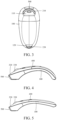
FIG. 1 is a front view of an input device disclosed in an embodiment of this application; -
FIG. 2 is a top view of an input device disclosed in an embodiment of this application; -
FIG. 3 is a bottom view of an input device disclosed in an embodiment of this application; -
FIG. 4 is a schematic diagram of an input device in a first state disclosed in an embodiment of this application; and -
FIG. 5 is a schematic diagram of an input device in a second state disclosed in an embodiment of this application. -
- 100-Device housing, 110-First sensing support surface, 120-Second sensing support surface,
- 210-First non-slip pad, 220-Second non-slip pad,
- 300-First key, 310-First sub-key, 320-Second sub-key, 330-Scroll wheel,
- 400-Touchpad, and
- 500-Second key.
- In order to make the objectives, technical solutions and advantages of this application clearer, the technical solutions of this application will be described clearly and completely in combination with specific embodiments of this application and corresponding accompanying drawings. Obviously, the described embodiments are only part of the embodiments of this application and not the whole embodiments.
- The terms "first", "second", and the like in the specification and claims of the application are intended to distinguish similar objects, but not intended to describe a specific order or sequence. It should be understood that the data used in this way can be interchanged in appropriate cases, so that the embodiments of this application can be implemented in an order other than those illustrated or described herein. In addition, in the specification and claims, "and/or" refers to at least one of connected objects, and the character "/" generally indicates that the front and rear associated objects are in an "or" relationship.
- The technical solutions disclosed in the embodiments of this application are described in detail below with reference to the accompanying drawings.
- As shown in
FIG. 1 to FIG. 5 , embodiments of this application disclose an input device, and the input device is configured to operate an electronic device. The input device includes a device body, atouchpad 400, and afirst key 300. - The device body is a main part of the input device, and the device body includes main functional devices, such as a handheld part, a circuit board, and a chip. The handheld part is a part held by a user, and the handheld part can be deformed. The handheld part has a first state and a second state, and the handheld part can switch between the first state and the second state through deformation. In a case that the handheld part is in the first state, a curvature of the handheld part is a first curvature. In a case that the handheld part is in the second state, the curvature of the handheld part is a second curvature; and the first curvature is greater than the second curvature. That is to say, the handheld part in the first state is more curved than the handheld part in the second state, and a height of the input device is larger. Optionally, the handheld part can be made of a deformable material or the handheld part has a deformable structure.
- In an embodiment of this application, by changing a curvature of the handheld part in different use environments, the fit between an input device and a palm of a user is better, so that the user has a relatively comfortable sense of grip in different use environments. By adjusting the curvature of the handheld part, the user can make the input device switch freely in different environments, so that the input device has better compatibility, thereby further improving the user experience.
- For example, in a case that the handheld part is in the first state, the curvature of the handheld part is relatively large, and the handheld part is more curved, so that the height of the input device is increased and the position on the input device supporting the center of the palm of the user is fuller and more rounded. In this case, the input device can be used in a desktop environment, and the input device can better support the center of the palm of the user. In a case that the handheld part is in the second state, the curvature of the handheld part is relatively small, and the height of the input device is relatively small. This case is more suitable for the user to hold the input device around with one hand or hold the input device with both hands, and the palm of the user can be closer to the surface of the handheld part, so that the user has a better sense of grip.
- Optionally, the input device disclosed in the embodiments of this application can further include a data connection line, and data transmission of the input device and the electronic device can be carried out through the data connection line. Alternatively, a first wireless data transmission module can be arranged in the input device, the electronic device is equipped with a second wireless data transmission module, and the input device and the electronic device can carry out the data transmission through the first wireless data transmission module and the second wireless data transmission module. In a case that the handheld part is in the first state, the
first key 300 is in an active state; and in a case that the handheld part is in the second state, thetouchpad 400 is in the active state. In a case that thefirst key 300 and thetouchpad 400 are in the active state, thefirst key 300 and thetouchpad 400 can respond to an input state of the user. In a case that the handheld part is in the first state, the user can operate the electronic device through thefirst key 300; and in a case that the handheld part is in the second state, the user can operate the electronic device through thetouchpad 400. In this solution, the handheld part has corresponding operation control keys in different states, thereby meeting operation requirements of the input devices in the different states. - In the foregoing embodiment, in a case that the handheld part is in the first state, when the
touchpad 400 is in the active state, the user is easy to touch thetouchpad 400 when using the input device, and then easy to cause a misoperation of the input device. In a case that the handheld part is in the second state, it is also easy to cause the above problem when thefirst key 300 is in the active state. In an optional embodiment, in a case that the handheld part is in the first state, thetouchpad 400 can be in an inactive state; and in a case that the handheld part is in the second state, thefirst key 300 can be in the inactive state. In a case that the handheld part is in the first state, thetouchpad 400 cannot respond to the input state of the user. That is to say, in this case, thetouchpad 400 cannot operate the electronic device, so to avoid the misoperation of the user. Certainly, in a case that the handheld part is in the second state, thefirst key 300 cannot respond to the input state of the user. That is to say, in this case, thefirst key 300 cannot operate the electronic device. - For ease of the operation of the input device, the input device disclosed in the embodiments of this application further includes a
second key 500, and thesecond key 500 is arranged on the device body. Thesecond key 500 can be used in conjunction with thetouchpad 400, thereby improving the operational performance of the input device. For example, thetouchpad 400 can be a direction control key, and thesecond key 500 can be a determining control key. - In a case that the handheld part is in the first state, the
second key 500 is in an inactive state; and in a case that the handheld part is in the second state, thesecond key 500 is in the active state. In this case, the handheld part is in the second state, and thesecond key 500 can operate the electronic device. In a case that the handheld part is in the first state, thesecond key 500 cannot operate the electronic device, thereby avoiding the misoperation of the input device. - In an optional embodiment, the
second key 500 and thetouchpad 400 can be located on the same side of the device body. In this solution, when the user holds the input device with both hands, the thumb of one hand of the user can operate thetouchpad 400, and the thumb of the other hand can operate thesecond key 500, thereby making the operation of the input device convenient. - In the foregoing embodiment, when the user holds the input device with one hand, the thumb of the user needs to operate both the
touchpad 400 and thesecond key 500, making the operation inconvenient. Therefore, in another optional embodiment, thesecond key 500 and thetouchpad 400 can be located on adjacent two sides of the device body. In this case, the thumb of the user is close to a top part of the input device, so that thetouchpad 400 can be operated; and the index finger of the user is close to a side part of the input device, so that thesecond key 500 can be operated, making the operation of the input device more convenient when the input device is held with one hand. - In a case that the handheld part is in the first state, the input device is a mouse, and in a case that the handheld part is in the second state, the input device is an operating handle. In this solution, the input device can realize the operation functions of such two devices as the mouse and the operating handle, which makes it more convenient for the user to use and carry the input device. In this case, the input device can take both office and game functions into account, which can improve the compatibility of the input device.
- The
input device 100 disclosed in the embodiments of this application can include adevice housing 100, thedevice housing 100 provides an installation foundation for some functional devices of the input device, and the handheld part and the device housing can be two independent parts, but this method makes the volume of the input device relatively large. In another optional embodiment, the handheld part can include at least one part of thedevice housing 100, and the at least one part of the device housing can be made of a deformable material. In this solution, thedevice housing 100 can be configured to provide the installation foundation for the some functional devices of the input device, and can be further configured for the user to hold, so as to make the volume of the input device relatively small and make it convenient to carry the input device. - Optionally, a corresponding structure inside a part of the
device housing 100 for holding, for example, a circuit board in thedevice housing 100 can be deformed with the deformation of thedevice housing 100. The circuit board can be a flexible circuit board, and therefore can be deformed with thedevice housing 100. - In another optional embodiment, a bottom surface of the
device housing 100 may include a firstsensing support surface 110 and a secondsensing support surface 120, the firstsensing support surface 110 and the secondsensing support surface 120 may be both planar, the firstsensing support surface 110 and the secondsensing support surface 120 may be located at two ends of thedevice housing 100 respectively, and in a case that the handheld part is in the first state, the firstsensing support surface 110 and the secondsensing support surface 120 are coplanar. In this solution, in a case that the handheld part is in the first state, the input device can be applied to the desktop environment, and the firstsensing support surface 110 and the secondsensing support surface 120 are in contact with a desktop, and therefore can be used for supporting the input device, thereby enabling the input device to move stably on the desktop. In addition, the firstsensing support surface 110 and the secondsensing support surface 120 control a movement of a cursor of the electronic device by sensing a movement of the input device (similar to controlling the movement of the cursor when the mouse moves). - Optionally, the first
sensing support surface 110 and the secondsensing support surface 120 can adopt a method of photoelectric sensing, and can also adopt a method of capacitive sensing. This is not limited herein. - In an optional embodiment, the input device disclosed in the embodiments of this application can further include a first
non-slip pad 210, and the firstnon-slip pad 210 covers at least one part of the firstsensing support surface 110. This solution can prevent the firstsensing support surface 110 from slipping on the desktop. - Further, the input device can further include a second
non-slip pad 220, and the secondnon-slip pad 220 covers at least one part of the secondsensing support surface 120. This solution can prevent the secondsensing support surface 120 from slipping on the desktop. - Optionally, the first
non-slip pad 210 and the secondnon-slip pad 220 can be made of a material such as silicone or rubber, and certainly can also be made of another material. This is not limited herein. - This application discloses a type of switching structure of the handheld part. Certainly, the handheld part can also adopt other switching structures. This is not limited herein. Specifically, the handheld part can further include an inner deformation positioning member arranged in the
device housing 100, the inner deformation positioning member is configured to keep thedevice housing 100 in the first state, and the inner deformation positioning member is not deformed with the housing. One of thedevice housing 100 and the inner deformation positioning member is provided with a first clamping part, the other one thereof is provided with a second clamping part, and in a case that the handheld part is in the first state, the first clamping part is engaged with the second clamping part; and in a case that the handheld part is in the second state, the first clamping part is separated from the second clamping part. In a specific operation process, when the handheld part is switched from the second state to the first state, the user can exert a force on thedevice housing 100, so as to bend thedevice housing 100 and cause the first clamping part to be engaged with the second clamping part; when the handheld part is switched from the first state to the second state, the user can exert a reverse force on thedevice housing 100, so as to cause the first clamping part to be separated from the second clamping part. In this solution, after the first clamping part is engaged with the second clamping part, the deformation of thedevice housing 100 can be avoided, so as to keep thedevice housing 100 in the first state stably. - This application further discloses a second type of switching structure of the handheld part. Specifically, the handheld part further includes an inner deformation positioning member arranged in the
device housing 100, the inner deformation positioning member is configured to keep thedevice housing 100 in the first state, and the inner deformation positioning member is not deformed with the housing. One of thedevice housing 100 and the inner deformation positioning member is provided with a magnetic member, the other one thereof is provided with a magnetic attraction member, and in a case that the handheld part is in the first state, the magnetic member is separated from the magnetic attraction member; and in a case that the handheld part is in the second state, the magnetic member is in magnetic attraction fit with the magnetic attraction member. In a specific operation process, when the handheld part is switched from the second state to the first state, the user can cause the magnetic member to be magnetically opposite to the magnetic attraction member, and the magnetic member is in magnetic attraction fit with the magnetic attraction member, so as to bend thedevice housing 100; when the handheld part is switched from the first state to the second state, the user can cause the magnetic member to be magnetically the same as the magnetic attraction member or to be non-magnetic, to separate the magnetic member from the magnetic attraction member, thereby restoring thedevice housing 100 to the second state. In this solution, the switching between the first state and the second state of the handheld part can be carried out through the fit between the magnetic member and the magnetic attraction member, so as to make the switching method of the input device simple and convenient. - Optionally, each of the magnetic member and the magnetic attraction member can be an electromagnetic coil; or the magnetic member is an electromagnetic coil and the magnetic attraction member is a permanent magnet. The magnetic member can be a permanent magnet, the magnetic attraction member can be a metal part, and the user exert an external force on the
device housing 100, so that the switching between the first state and the second state of the handheld part is carried out. - In an optional embodiment, the handheld part can be a memory alloy member. In this solution, the memory alloy member can be kept in a certain state in which the memory alloy member is deformed, so that there is no need to set other deformation positioning members in the
device housing 100 to maintain the deformation state of the handheld part, thereby making the structure of the handheld part simple. Optionally, the switching between the first state and the second state of the memory alloy member can be controlled by changing a temperature of the memory alloy member. - In an optional embodiment, the
first key 300 can include afirst sub-key 310, asecond sub-key 320, and ascroll wheel 330, a part of thescroll wheel 330 is arranged in an assembly gap between thefirst sub-key 310 and thesecond sub-key 320, thescroll wheel 330 protrudes from an outer surface of the device body, and a protruding part of thescroll wheel 330 makes it convenient for the user to operate. In this solution, thefirst key 300 can include a plurality of sub-keys, so that thefirst key 300 can carry out more operation functions. In addition, a setting method of thefirst key 300 also meets the key layout method of the mouse, so that the input device can also be used as the mouse, thereby improving the compatibility of the input device. - The embodiments of this application further disclose an electronic device input system, and the disclosed electronic device input system includes an electronic device and the input device in any one of the foregoing embodiments.
- The electronic device disclosed in the embodiments of this application can be a smartphone, a tablet computer, an e-book reader, a wearable device (such as a smart watch), a video game console, and other devices, and the embodiments of this application do not limit specific types of the electronic device.
- In the above embodiments of the application, the differences between embodiments are mainly described. As long as the different optimization features between embodiments are not contradictory, they can be combined to form better embodiments. Considering the conciseness of the writing, no repeated description is provided.
- The above are only embodiments of this application and are not intended to limit this application. For a person skilled in the art, various modifications and changes can be made to this application without departing from the scope of the present invention as defined by the appended set of claims.
Claims (9)
- An input device, comprising a device body, a touchpad (400), a first key (300) and a second key (500), whereinthe device body comprises a handheld part, the first key (300) and the touchpad (400) are arranged on the device body and located on the same side of the device body, and in a case that the handheld part is in a first state, a curvature of the handheld part is a first curvature; and in a case that the handheld part is in a second state, the curvature of the handheld part is a second curvature, and the first curvature is greater than the second curvature;the second key (500) is arranged on the device body;the second key (500) and the touchpad (400) are located on the same side of the device body; or the second key (500) and the touchpad (400) are located on adjacent two sides of the device body;in a case that the handheld part is in the first state, the input device is a mouse, and in a case that the handheld part is in the second state, the input device is an operating handle that is freely usable in space;in the case that the handheld part is in the first state, the first key (300) is in an active state and the second key (500) is in an inactive state; and in the case that the handheld part is in the second state, the second key (500) is in the active state and the touchpad (400) is in the active state.
- The input device according to claim 1, wherein in the case that the handheld part is in the first state, the touchpad (400) is in the inactive state; and in the case that the handheld part is in the second state, the first key (300) is in the inactive state.
- The input device according to claim 1, wherein the device body comprises a device housing (100), the handheld part comprises at least one part of the device housing (100), a bottom surface of the device housing (100) comprises a first sensing support surface (110) and a second sensing support surface (120), the first sensing support surface (110) and the second sensing support surface (120) are both planar, the first sensing support surface (110) and the second sensing support surface (120) are located at two ends of the device housing respectively, and in the case that the handheld part is in the first state, the first sensing support surface (110) and the second sensing support surface (120) are coplanar.
- The input device according to claim 3, wherein the input device further comprises a first non-slip pad (210), and the first non-slip pad (210) covers at least one part of the first sensing support surface (110); and/or
the input device further comprises a second non-slip pad (220), and the second non-slip pad (220) covers at least one part of the second sensing support surface (120). - The input device according to claim 1, wherein the device body comprises a device housing, the handheld part comprises at least one part of the device housing (100) and an inner deformation positioning member arranged in the device housing (100), one of the device housing (100) and the inner deformation positioning member is provided with a first clamping part, the other one thereof is provided with a second clamping part, and in the case that the handheld part is in the first state, the first clamping part is engaged with the second clamping part; and in the case that the handheld part is in the second state, the first clamping part is separated from the second clamping part.
- The input device according to claim 1, wherein the device body comprises a device housing, the handheld part comprises at least one part of the device housing (100) and an inner deformation positioning member arranged in the device housing (100), one of the device housing (100) and the inner deformation positioning member is provided with a magnetic member, the other one thereof is provided with a magnetic attraction member, and in the case that the handheld part is in the first state, the magnetic member is in magnetic attraction fit with the magnetic attraction member; and in the case that the handheld part is in the second state, the magnetic member is separated from the magnetic attraction member.
- The input device according to claim 1, wherein the handheld part is a memory alloy member.
- The input device according to claim 1, wherein the first key (300) comprises a first sub-key (310), a second sub-key (320), and a scroll wheel (330), a part of the scroll wheel (330) is arranged in an assembly gap between the first sub-key (310) and the second sub-key (320), and the scroll wheel (330) protrudes from an outer surface of the device body.
- An electronic device input system, characterized by comprising an electronic device and the input device according to any one of claims 1 to 8.
Applications Claiming Priority (2)
| Application Number | Priority Date | Filing Date | Title |
|---|---|---|---|
| CN202010336290.2A CN111459317B (en) | 2020-04-24 | 2020-04-24 | Input devices and electronic device input systems |
| PCT/CN2021/089355 WO2021213506A1 (en) | 2020-04-24 | 2021-04-23 | Input device and electronic device input system |
Publications (3)
| Publication Number | Publication Date |
|---|---|
| EP4141624A1 EP4141624A1 (en) | 2023-03-01 |
| EP4141624A4 EP4141624A4 (en) | 2023-09-06 |
| EP4141624B1 true EP4141624B1 (en) | 2025-01-08 |
Family
ID=71682715
Family Applications (1)
| Application Number | Title | Priority Date | Filing Date |
|---|---|---|---|
| EP21792838.1A Active EP4141624B1 (en) | 2020-04-24 | 2021-04-23 | Input device and electronic device input system |
Country Status (7)
| Country | Link |
|---|---|
| US (1) | US12111987B2 (en) |
| EP (1) | EP4141624B1 (en) |
| JP (1) | JP7504219B2 (en) |
| KR (1) | KR102723365B1 (en) |
| CN (1) | CN111459317B (en) |
| ES (1) | ES3014710T3 (en) |
| WO (1) | WO2021213506A1 (en) |
Families Citing this family (2)
| Publication number | Priority date | Publication date | Assignee | Title |
|---|---|---|---|---|
| CN111459317B (en) * | 2020-04-24 | 2024-02-27 | 维沃移动通信有限公司 | Input devices and electronic device input systems |
| CN112818825B (en) * | 2021-01-28 | 2024-02-23 | 维沃移动通信有限公司 | Working status determination method and device |
Family Cites Families (13)
| Publication number | Priority date | Publication date | Assignee | Title |
|---|---|---|---|---|
| US5994710A (en) * | 1998-04-30 | 1999-11-30 | Hewlett-Packard Company | Scanning mouse for a computer system |
| US20030214484A1 (en) | 2002-05-20 | 2003-11-20 | Haywood Chad Christian | Convertible mouse |
| JP2007004289A (en) | 2005-06-21 | 2007-01-11 | Fujinon Corp | Mouse and mouse holder |
| JP3143935U (en) * | 2008-05-30 | 2008-08-07 | 忠献 林 | Mouse bottom pad |
| US9069393B2 (en) * | 2010-06-18 | 2015-06-30 | Microsoft Technology Licensing, Llc | Computer mouse sleeve |
| EP2400376A1 (en) * | 2010-06-28 | 2011-12-28 | Giga-Byte Technology Co., Ltd. | Combination mouse and touch input device |
| CN102339144B (en) * | 2010-07-19 | 2015-12-09 | 技嘉科技股份有限公司 | Computer input device with mouse mode and touch mode |
| US10592008B1 (en) * | 2017-09-05 | 2020-03-17 | Apple Inc. | Mouse having a shape-changing enclosure |
| US11132059B2 (en) * | 2017-09-14 | 2021-09-28 | Logitech Europe S.A. | Input device with haptic interface |
| US20190187819A1 (en) * | 2017-12-18 | 2019-06-20 | Immersion Corporation | Haptically-Enabled Peripheral Usable for Two-Dimensional and Three-Dimensional Tracking |
| CN110221714A (en) * | 2018-03-01 | 2019-09-10 | 致伸科技股份有限公司 | Mouse |
| CN208477487U (en) * | 2018-08-09 | 2019-02-05 | 合肥联宝信息技术有限公司 | A kind of input equipment and electronic equipment |
| CN111459317B (en) * | 2020-04-24 | 2024-02-27 | 维沃移动通信有限公司 | Input devices and electronic device input systems |
-
2020
- 2020-04-24 CN CN202010336290.2A patent/CN111459317B/en active Active
-
2021
- 2021-04-23 EP EP21792838.1A patent/EP4141624B1/en active Active
- 2021-04-23 KR KR1020227040205A patent/KR102723365B1/en active Active
- 2021-04-23 ES ES21792838T patent/ES3014710T3/en active Active
- 2021-04-23 WO PCT/CN2021/089355 patent/WO2021213506A1/en not_active Ceased
- 2021-04-23 JP JP2022562093A patent/JP7504219B2/en active Active
-
2022
- 2022-10-19 US US17/968,977 patent/US12111987B2/en active Active
Also Published As
| Publication number | Publication date |
|---|---|
| KR20220167392A (en) | 2022-12-20 |
| CN111459317B (en) | 2024-02-27 |
| US20230038885A1 (en) | 2023-02-09 |
| US12111987B2 (en) | 2024-10-08 |
| EP4141624A4 (en) | 2023-09-06 |
| ES3014710T3 (en) | 2025-04-24 |
| JP7504219B2 (en) | 2024-06-21 |
| KR102723365B1 (en) | 2024-10-28 |
| JP2023523175A (en) | 2023-06-02 |
| WO2021213506A1 (en) | 2021-10-28 |
| CN111459317A (en) | 2020-07-28 |
| EP4141624A1 (en) | 2023-03-01 |
Similar Documents
| Publication | Publication Date | Title |
|---|---|---|
| US11194394B2 (en) | Multipurpose computer mouse | |
| JP6516813B2 (en) | Standardization of pressure sensitive keys | |
| CN111273733B (en) | Input device attachment | |
| KR101036532B1 (en) | Human interface and input system for use with a hand-held electronic device | |
| US20150363007A1 (en) | Data input systems for handheld devices | |
| WO2006080858A1 (en) | Computer mouse peripheral | |
| US9240299B2 (en) | Pivotable key structure | |
| US10928908B2 (en) | Haptic device, for interaction with virtual reality or augmented reality systems | |
| US12111987B2 (en) | Input device and electronic device input system | |
| KR20040081697A (en) | Mouse typed touch pad by implementing click and draw operation like as mouse operation | |
| US6366274B1 (en) | Hand-held input devices for personal computer systems | |
| JP7339470B2 (en) | controller and computer | |
| US8125775B2 (en) | Thin type mouse | |
| US12554336B2 (en) | Wearable keyboard for electronic devices | |
| CN110658926A (en) | Ring type mouse | |
| CN101424986B (en) | Novel mouse device | |
| JP2011223613A (en) | Mobile information terminal with holding pads | |
| JP2001034389A (en) | Electronic device and displacement method | |
| EP2273352A1 (en) | Computer mouse | |
| CN201060465Y (en) | computer input device | |
| JPH10111740A (en) | Data input device |
Legal Events
| Date | Code | Title | Description |
|---|---|---|---|
| STAA | Information on the status of an ep patent application or granted ep patent |
Free format text: STATUS: THE INTERNATIONAL PUBLICATION HAS BEEN MADE |
|
| PUAI | Public reference made under article 153(3) epc to a published international application that has entered the european phase |
Free format text: ORIGINAL CODE: 0009012 |
|
| STAA | Information on the status of an ep patent application or granted ep patent |
Free format text: STATUS: REQUEST FOR EXAMINATION WAS MADE |
|
| 17P | Request for examination filed |
Effective date: 20221102 |
|
| AK | Designated contracting states |
Kind code of ref document: A1 Designated state(s): AL AT BE BG CH CY CZ DE DK EE ES FI FR GB GR HR HU IE IS IT LI LT LU LV MC MK MT NL NO PL PT RO RS SE SI SK SM TR |
|
| DAV | Request for validation of the european patent (deleted) | ||
| DAX | Request for extension of the european patent (deleted) | ||
| A4 | Supplementary search report drawn up and despatched |
Effective date: 20230808 |
|
| RIC1 | Information provided on ipc code assigned before grant |
Ipc: G06F 3/038 20130101ALI20230802BHEP Ipc: G06F 3/0354 20130101AFI20230802BHEP |
|
| GRAP | Despatch of communication of intention to grant a patent |
Free format text: ORIGINAL CODE: EPIDOSNIGR1 |
|
| STAA | Information on the status of an ep patent application or granted ep patent |
Free format text: STATUS: GRANT OF PATENT IS INTENDED |
|
| INTG | Intention to grant announced |
Effective date: 20241017 |
|
| GRAS | Grant fee paid |
Free format text: ORIGINAL CODE: EPIDOSNIGR3 |
|
| GRAA | (expected) grant |
Free format text: ORIGINAL CODE: 0009210 |
|
| STAA | Information on the status of an ep patent application or granted ep patent |
Free format text: STATUS: THE PATENT HAS BEEN GRANTED |
|
| AK | Designated contracting states |
Kind code of ref document: B1 Designated state(s): AL AT BE BG CH CY CZ DE DK EE ES FI FR GB GR HR HU IE IS IT LI LT LU LV MC MK MT NL NO PL PT RO RS SE SI SK SM TR |
|
| REG | Reference to a national code |
Ref country code: GB Ref legal event code: FG4D |
|
| REG | Reference to a national code |
Ref country code: CH Ref legal event code: EP |
|
| REG | Reference to a national code |
Ref country code: DE Ref legal event code: R096 Ref document number: 602021024733 Country of ref document: DE |
|
| REG | Reference to a national code |
Ref country code: IE Ref legal event code: FG4D |
|
| REG | Reference to a national code |
Ref country code: NL Ref legal event code: FP |
|
| REG | Reference to a national code |
Ref country code: ES Ref legal event code: FG2A Ref document number: 3014710 Country of ref document: ES Kind code of ref document: T3 Effective date: 20250424 |
|
| REG | Reference to a national code |
Ref country code: LT Ref legal event code: MG9D |
|
| REG | Reference to a national code |
Ref country code: AT Ref legal event code: MK05 Ref document number: 1758765 Country of ref document: AT Kind code of ref document: T Effective date: 20250108 |
|
| PG25 | Lapsed in a contracting state [announced via postgrant information from national office to epo] |
Ref country code: RS Free format text: LAPSE BECAUSE OF FAILURE TO SUBMIT A TRANSLATION OF THE DESCRIPTION OR TO PAY THE FEE WITHIN THE PRESCRIBED TIME-LIMIT Effective date: 20250408 |
|
| PG25 | Lapsed in a contracting state [announced via postgrant information from national office to epo] |
Ref country code: FI Free format text: LAPSE BECAUSE OF FAILURE TO SUBMIT A TRANSLATION OF THE DESCRIPTION OR TO PAY THE FEE WITHIN THE PRESCRIBED TIME-LIMIT Effective date: 20250108 |
|
| PG25 | Lapsed in a contracting state [announced via postgrant information from national office to epo] |
Ref country code: PL Free format text: LAPSE BECAUSE OF FAILURE TO SUBMIT A TRANSLATION OF THE DESCRIPTION OR TO PAY THE FEE WITHIN THE PRESCRIBED TIME-LIMIT Effective date: 20250108 |
|
| PGFP | Annual fee paid to national office [announced via postgrant information from national office to epo] |
Ref country code: DE Payment date: 20250305 Year of fee payment: 5 |
|
| PGFP | Annual fee paid to national office [announced via postgrant information from national office to epo] |
Ref country code: ES Payment date: 20250508 Year of fee payment: 5 |
|
| PG25 | Lapsed in a contracting state [announced via postgrant information from national office to epo] |
Ref country code: NO Free format text: LAPSE BECAUSE OF FAILURE TO SUBMIT A TRANSLATION OF THE DESCRIPTION OR TO PAY THE FEE WITHIN THE PRESCRIBED TIME-LIMIT Effective date: 20250408 Ref country code: IS Free format text: LAPSE BECAUSE OF FAILURE TO SUBMIT A TRANSLATION OF THE DESCRIPTION OR TO PAY THE FEE WITHIN THE PRESCRIBED TIME-LIMIT Effective date: 20250508 |
|
| PG25 | Lapsed in a contracting state [announced via postgrant information from national office to epo] |
Ref country code: HR Free format text: LAPSE BECAUSE OF FAILURE TO SUBMIT A TRANSLATION OF THE DESCRIPTION OR TO PAY THE FEE WITHIN THE PRESCRIBED TIME-LIMIT Effective date: 20250108 |
|
| PG25 | Lapsed in a contracting state [announced via postgrant information from national office to epo] |
Ref country code: PT Free format text: LAPSE BECAUSE OF FAILURE TO SUBMIT A TRANSLATION OF THE DESCRIPTION OR TO PAY THE FEE WITHIN THE PRESCRIBED TIME-LIMIT Effective date: 20250508 Ref country code: LV Free format text: LAPSE BECAUSE OF FAILURE TO SUBMIT A TRANSLATION OF THE DESCRIPTION OR TO PAY THE FEE WITHIN THE PRESCRIBED TIME-LIMIT Effective date: 20250108 |
|
| PG25 | Lapsed in a contracting state [announced via postgrant information from national office to epo] |
Ref country code: GR Free format text: LAPSE BECAUSE OF FAILURE TO SUBMIT A TRANSLATION OF THE DESCRIPTION OR TO PAY THE FEE WITHIN THE PRESCRIBED TIME-LIMIT Effective date: 20250409 Ref country code: BG Free format text: LAPSE BECAUSE OF FAILURE TO SUBMIT A TRANSLATION OF THE DESCRIPTION OR TO PAY THE FEE WITHIN THE PRESCRIBED TIME-LIMIT Effective date: 20250108 |
|
| PG25 | Lapsed in a contracting state [announced via postgrant information from national office to epo] |
Ref country code: AT Free format text: LAPSE BECAUSE OF FAILURE TO SUBMIT A TRANSLATION OF THE DESCRIPTION OR TO PAY THE FEE WITHIN THE PRESCRIBED TIME-LIMIT Effective date: 20250108 |
|
| PG25 | Lapsed in a contracting state [announced via postgrant information from national office to epo] |
Ref country code: SE Free format text: LAPSE BECAUSE OF FAILURE TO SUBMIT A TRANSLATION OF THE DESCRIPTION OR TO PAY THE FEE WITHIN THE PRESCRIBED TIME-LIMIT Effective date: 20250108 |
|
| PG25 | Lapsed in a contracting state [announced via postgrant information from national office to epo] |
Ref country code: SM Free format text: LAPSE BECAUSE OF FAILURE TO SUBMIT A TRANSLATION OF THE DESCRIPTION OR TO PAY THE FEE WITHIN THE PRESCRIBED TIME-LIMIT Effective date: 20250108 |
|
| REG | Reference to a national code |
Ref country code: DE Ref legal event code: R097 Ref document number: 602021024733 Country of ref document: DE |
|
| PG25 | Lapsed in a contracting state [announced via postgrant information from national office to epo] |
Ref country code: DK Free format text: LAPSE BECAUSE OF FAILURE TO SUBMIT A TRANSLATION OF THE DESCRIPTION OR TO PAY THE FEE WITHIN THE PRESCRIBED TIME-LIMIT Effective date: 20250108 |
|
| PG25 | Lapsed in a contracting state [announced via postgrant information from national office to epo] |
Ref country code: CZ Free format text: LAPSE BECAUSE OF FAILURE TO SUBMIT A TRANSLATION OF THE DESCRIPTION OR TO PAY THE FEE WITHIN THE PRESCRIBED TIME-LIMIT Effective date: 20250108 Ref country code: EE Free format text: LAPSE BECAUSE OF FAILURE TO SUBMIT A TRANSLATION OF THE DESCRIPTION OR TO PAY THE FEE WITHIN THE PRESCRIBED TIME-LIMIT Effective date: 20250108 |
|
| PG25 | Lapsed in a contracting state [announced via postgrant information from national office to epo] |
Ref country code: RO Free format text: LAPSE BECAUSE OF FAILURE TO SUBMIT A TRANSLATION OF THE DESCRIPTION OR TO PAY THE FEE WITHIN THE PRESCRIBED TIME-LIMIT Effective date: 20250108 |
|
| PG25 | Lapsed in a contracting state [announced via postgrant information from national office to epo] |
Ref country code: SK Free format text: LAPSE BECAUSE OF FAILURE TO SUBMIT A TRANSLATION OF THE DESCRIPTION OR TO PAY THE FEE WITHIN THE PRESCRIBED TIME-LIMIT Effective date: 20250108 |
|
| PLBE | No opposition filed within time limit |
Free format text: ORIGINAL CODE: 0009261 |
|
| STAA | Information on the status of an ep patent application or granted ep patent |
Free format text: STATUS: NO OPPOSITION FILED WITHIN TIME LIMIT |
|
| REG | Reference to a national code |
Ref country code: CH Ref legal event code: L10 Free format text: ST27 STATUS EVENT CODE: U-0-0-L10-L00 (AS PROVIDED BY THE NATIONAL OFFICE) Effective date: 20251119 |
|
| REG | Reference to a national code |
Ref country code: CH Ref legal event code: H13 Free format text: ST27 STATUS EVENT CODE: U-0-0-H10-H13 (AS PROVIDED BY THE NATIONAL OFFICE) Effective date: 20251125 |
|
| PG25 | Lapsed in a contracting state [announced via postgrant information from national office to epo] |
Ref country code: LU Free format text: LAPSE BECAUSE OF NON-PAYMENT OF DUE FEES Effective date: 20250423 |
|
| 26N | No opposition filed |
Effective date: 20251009 |
|
| PG25 | Lapsed in a contracting state [announced via postgrant information from national office to epo] |
Ref country code: MC Free format text: LAPSE BECAUSE OF FAILURE TO SUBMIT A TRANSLATION OF THE DESCRIPTION OR TO PAY THE FEE WITHIN THE PRESCRIBED TIME-LIMIT Effective date: 20250108 |
|
| REG | Reference to a national code |
Ref country code: BE Ref legal event code: MM Effective date: 20250430 |
|
| PG25 | Lapsed in a contracting state [announced via postgrant information from national office to epo] |
Ref country code: BE Free format text: LAPSE BECAUSE OF NON-PAYMENT OF DUE FEES Effective date: 20250430 |
|
| PG25 | Lapsed in a contracting state [announced via postgrant information from national office to epo] |
Ref country code: CH Free format text: LAPSE BECAUSE OF NON-PAYMENT OF DUE FEES Effective date: 20250430 |
|
| PGFP | Annual fee paid to national office [announced via postgrant information from national office to epo] |
Ref country code: GB Payment date: 20260312 Year of fee payment: 6 |
|
| PG25 | Lapsed in a contracting state [announced via postgrant information from national office to epo] |
Ref country code: IE Free format text: LAPSE BECAUSE OF NON-PAYMENT OF DUE FEES Effective date: 20250423 |
|
| PG25 | Lapsed in a contracting state [announced via postgrant information from national office to epo] |
Ref country code: IT Free format text: LAPSE BECAUSE OF NON-PAYMENT OF DUE FEES Effective date: 20250423 |
|
| PGFP | Annual fee paid to national office [announced via postgrant information from national office to epo] |
Ref country code: NL Payment date: 20260317 Year of fee payment: 6 |
|
| PGFP | Annual fee paid to national office [announced via postgrant information from national office to epo] |
Ref country code: FR Payment date: 20260309 Year of fee payment: 6 |