EP4141573A1 - Operation assisting tool and image forming apparatus including the operation assisting tool - Google Patents
Operation assisting tool and image forming apparatus including the operation assisting tool Download PDFInfo
- Publication number
- EP4141573A1 EP4141573A1 EP22191921.0A EP22191921A EP4141573A1 EP 4141573 A1 EP4141573 A1 EP 4141573A1 EP 22191921 A EP22191921 A EP 22191921A EP 4141573 A1 EP4141573 A1 EP 4141573A1
- Authority
- EP
- European Patent Office
- Prior art keywords
- sheet
- assisting tool
- operation assisting
- handle
- face
- Prior art date
- Legal status (The legal status is an assumption and is not a legal conclusion. Google has not performed a legal analysis and makes no representation as to the accuracy of the status listed.)
- Granted
Links
Images





Classifications
-
- G—PHYSICS
- G03—PHOTOGRAPHY; CINEMATOGRAPHY; ANALOGOUS TECHNIQUES USING WAVES OTHER THAN OPTICAL WAVES; ELECTROGRAPHY; HOLOGRAPHY
- G03G—ELECTROGRAPHY; ELECTROPHOTOGRAPHY; MAGNETOGRAPHY
- G03G21/00—Arrangements not provided for by groups G03G13/00 - G03G19/00, e.g. cleaning, elimination of residual charge
- G03G21/16—Mechanical means for facilitating the maintenance of the apparatus, e.g. modular arrangements
- G03G21/1604—Arrangement or disposition of the entire apparatus
- G03G21/1614—Measures for handling of apparatus by disabled persons
-
- G—PHYSICS
- G03—PHOTOGRAPHY; CINEMATOGRAPHY; ANALOGOUS TECHNIQUES USING WAVES OTHER THAN OPTICAL WAVES; ELECTROGRAPHY; HOLOGRAPHY
- G03G—ELECTROGRAPHY; ELECTROPHOTOGRAPHY; MAGNETOGRAPHY
- G03G21/00—Arrangements not provided for by groups G03G13/00 - G03G19/00, e.g. cleaning, elimination of residual charge
- G03G21/16—Mechanical means for facilitating the maintenance of the apparatus, e.g. modular arrangements
- G03G21/1604—Arrangement or disposition of the entire apparatus
- G03G21/1623—Means to access the interior of the apparatus
-
- G—PHYSICS
- G03—PHOTOGRAPHY; CINEMATOGRAPHY; ANALOGOUS TECHNIQUES USING WAVES OTHER THAN OPTICAL WAVES; ELECTROGRAPHY; HOLOGRAPHY
- G03G—ELECTROGRAPHY; ELECTROPHOTOGRAPHY; MAGNETOGRAPHY
- G03G15/00—Apparatus for electrographic processes using a charge pattern
- G03G15/65—Apparatus which relate to the handling of copy material
- G03G15/6502—Supplying of sheet copy material; Cassettes therefor
-
- G—PHYSICS
- G03—PHOTOGRAPHY; CINEMATOGRAPHY; ANALOGOUS TECHNIQUES USING WAVES OTHER THAN OPTICAL WAVES; ELECTROGRAPHY; HOLOGRAPHY
- G03G—ELECTROGRAPHY; ELECTROPHOTOGRAPHY; MAGNETOGRAPHY
- G03G21/00—Arrangements not provided for by groups G03G13/00 - G03G19/00, e.g. cleaning, elimination of residual charge
- G03G21/16—Mechanical means for facilitating the maintenance of the apparatus, e.g. modular arrangements
-
- G—PHYSICS
- G03—PHOTOGRAPHY; CINEMATOGRAPHY; ANALOGOUS TECHNIQUES USING WAVES OTHER THAN OPTICAL WAVES; ELECTROGRAPHY; HOLOGRAPHY
- G03G—ELECTROGRAPHY; ELECTROPHOTOGRAPHY; MAGNETOGRAPHY
- G03G21/00—Arrangements not provided for by groups G03G13/00 - G03G19/00, e.g. cleaning, elimination of residual charge
- G03G21/16—Mechanical means for facilitating the maintenance of the apparatus, e.g. modular arrangements
- G03G21/1604—Arrangement or disposition of the entire apparatus
-
- G—PHYSICS
- G03—PHOTOGRAPHY; CINEMATOGRAPHY; ANALOGOUS TECHNIQUES USING WAVES OTHER THAN OPTICAL WAVES; ELECTROGRAPHY; HOLOGRAPHY
- G03G—ELECTROGRAPHY; ELECTROPHOTOGRAPHY; MAGNETOGRAPHY
- G03G21/00—Arrangements not provided for by groups G03G13/00 - G03G19/00, e.g. cleaning, elimination of residual charge
- G03G21/16—Mechanical means for facilitating the maintenance of the apparatus, e.g. modular arrangements
- G03G21/1661—Mechanical means for facilitating the maintenance of the apparatus, e.g. modular arrangements means for handling parts of the apparatus in the apparatus
-
- G—PHYSICS
- G03—PHOTOGRAPHY; CINEMATOGRAPHY; ANALOGOUS TECHNIQUES USING WAVES OTHER THAN OPTICAL WAVES; ELECTROGRAPHY; HOLOGRAPHY
- G03G—ELECTROGRAPHY; ELECTROPHOTOGRAPHY; MAGNETOGRAPHY
- G03G21/00—Arrangements not provided for by groups G03G13/00 - G03G19/00, e.g. cleaning, elimination of residual charge
- G03G21/16—Mechanical means for facilitating the maintenance of the apparatus, e.g. modular arrangements
- G03G21/1661—Mechanical means for facilitating the maintenance of the apparatus, e.g. modular arrangements means for handling parts of the apparatus in the apparatus
- G03G21/1695—Mechanical means for facilitating the maintenance of the apparatus, e.g. modular arrangements means for handling parts of the apparatus in the apparatus for paper transport
-
- G—PHYSICS
- G03—PHOTOGRAPHY; CINEMATOGRAPHY; ANALOGOUS TECHNIQUES USING WAVES OTHER THAN OPTICAL WAVES; ELECTROGRAPHY; HOLOGRAPHY
- G03G—ELECTROGRAPHY; ELECTROPHOTOGRAPHY; MAGNETOGRAPHY
- G03G21/00—Arrangements not provided for by groups G03G13/00 - G03G19/00, e.g. cleaning, elimination of residual charge
- G03G21/16—Mechanical means for facilitating the maintenance of the apparatus, e.g. modular arrangements
- G03G21/18—Mechanical means for facilitating the maintenance of the apparatus, e.g. modular arrangements using a processing cartridge, whereby the process cartridge comprises at least two image processing means in a single unit
- G03G21/1839—Means for handling the process cartridge in the apparatus body
- G03G21/1842—Means for handling the process cartridge in the apparatus body for guiding and mounting the process cartridge, positioning, alignment, locks
- G03G21/1846—Means for handling the process cartridge in the apparatus body for guiding and mounting the process cartridge, positioning, alignment, locks using a handle for carrying or pulling out of the main machine, legs of casings
-
- G—PHYSICS
- G03—PHOTOGRAPHY; CINEMATOGRAPHY; ANALOGOUS TECHNIQUES USING WAVES OTHER THAN OPTICAL WAVES; ELECTROGRAPHY; HOLOGRAPHY
- G03G—ELECTROGRAPHY; ELECTROPHOTOGRAPHY; MAGNETOGRAPHY
- G03G2215/00—Apparatus for electrophotographic processes
- G03G2215/00004—Handling of entire apparatus
-
- G—PHYSICS
- G03—PHOTOGRAPHY; CINEMATOGRAPHY; ANALOGOUS TECHNIQUES USING WAVES OTHER THAN OPTICAL WAVES; ELECTROGRAPHY; HOLOGRAPHY
- G03G—ELECTROGRAPHY; ELECTROPHOTOGRAPHY; MAGNETOGRAPHY
- G03G2215/00—Apparatus for electrophotographic processes
- G03G2215/00135—Handling of parts of the apparatus
-
- G—PHYSICS
- G03—PHOTOGRAPHY; CINEMATOGRAPHY; ANALOGOUS TECHNIQUES USING WAVES OTHER THAN OPTICAL WAVES; ELECTROGRAPHY; HOLOGRAPHY
- G03G—ELECTROGRAPHY; ELECTROPHOTOGRAPHY; MAGNETOGRAPHY
- G03G2221/00—Processes not provided for by group G03G2215/00, e.g. cleaning or residual charge elimination
- G03G2221/16—Mechanical means for facilitating the maintenance of the apparatus, e.g. modular arrangements and complete machine concepts
- G03G2221/1678—Frame structures
- G03G2221/1684—Frame structures using extractable subframes, e.g. on rails or hinges
-
- G—PHYSICS
- G03—PHOTOGRAPHY; CINEMATOGRAPHY; ANALOGOUS TECHNIQUES USING WAVES OTHER THAN OPTICAL WAVES; ELECTROGRAPHY; HOLOGRAPHY
- G03G—ELECTROGRAPHY; ELECTROPHOTOGRAPHY; MAGNETOGRAPHY
- G03G2221/00—Processes not provided for by group G03G2215/00, e.g. cleaning or residual charge elimination
- G03G2221/16—Mechanical means for facilitating the maintenance of the apparatus, e.g. modular arrangements and complete machine concepts
- G03G2221/18—Cartridge systems
- G03G2221/183—Process cartridge
- G03G2221/1846—Process cartridge using a handle for carrying or pulling out of the main machine
Definitions
- Embodiments of the present disclosure relate to an operation assisting tool and an image forming apparatus including the operation assisting tool.
- Various types of image forming apparatuses are known in the art to include a drawer unit that is drawable from the housing of an image forming apparatus.
- Japanese Unexamined Patent Application Publication No. 2021-080090 discloses an image forming apparatus including a sheet tray as a drawer.
- a handle is attached to the sheet tray, so that a user grips and pulls the handle to draw the sheet tray from the housing of an image forming apparatus.
- the handle of the sheet tray as a drawer is a part touched by the hand of an unspecified number of users. For this reason, if the handle is touched by the hand with virus being adhered, infection of virus may spread through the handle.
- an object of the present disclosure is to provide an operation assisting tool that prevents spreading of virus infection via the handle of a component of an image forming apparatus including such an operation assisting tool.
- Embodiments of the present disclosure described herein provide a novel operation assisting tool including a gripper and an engagement portion to engage with a handle of a drawer drawable from a housing of an image forming apparatus.
- an image forming apparatus including a housing, a drawer drawable from the housing, and the above-described operation assisting tool.
- an operation assisting tool prevents spreading of virus infection via the handle of a component of an image forming apparatus including such an operation assisting tool.
- spatially relative terms such as “beneath,” “below,” “lower,” “above,” “upper” and the like may be used herein for ease of description to describe one element or feature's relationship to another element(s) or feature(s) as illustrated in the figures. It will be understood that the spatially relative terms are intended to encompass different orientations of the device in use or operation in addition to the orientation depicted in the figures. For example, if the device in the figures is turned over, elements describes as “below” or “beneath” other elements or features would then be oriented “above” the other elements or features. Thus, term such as “below” can encompass both an orientation of above and below. The device may be otherwise oriented (rotated 90 degrees or at other orientations) and the spatially relative descriptors herein interpreted accordingly.
- FIG. 1 a description is given of an overall configuration and operations of an image forming apparatus 1 according to an embodiment of the present disclosure.
- FIG. 1 is a schematic diagram illustrating a configuration of an image forming apparatus according to an embodiment of the present disclosure.
- the image forming apparatus 1 includes a document reading device 2, an exposure device 3, an image forming device 4, a photoconductor drum 5, a transfer device 7, a document conveyance device 10, sheet feeding devices 12 and 13, a bypass sheet feeding device 16, a registration roller pair 17, a fixing device 20, a fixing roller 21, a pressure roller 22, and a sheet ejection tray 31.
- the document reading device 2 optically reads image data of an original document D.
- the exposure device 3 emits an exposure light L based on the image data read by the document reading device 2 to irradiate the exposure light L onto a surface of the photoconductor drum 5 that functions as an image bearer.
- the image forming device 4 forms a toner image on the surface of the photoconductor drum 5.
- the transfer device 7 transfers the toner image formed on the surface of the photoconductor drum 5 onto a sheet P serving as a recording medium.
- the document conveyance device 10 corresponding to an automatic document feeder (ADF) conveys the original document D set in the document conveyance device 10 to the document reading device 2.
- the sheet feeding device 12 feeds sheets P accommodated in a sheet tray 12a, and the sheet feeding device 13 feeds sheets P stored in a sheet tray 13a.
- the bypass sheet feeding device 16 feeds sheets P that is manually set by a user.
- the registration roller pair 17 serving as a conveyance roller pair conveys the sheet P toward the transfer device 7.
- the fixing device 20 fixes a toner image (unfixed image) borne on the on the sheet P to the sheet P.
- the fixing device 20 includes the fixing roller 21 and the pressure roller 22.
- the sheet ejection tray 31 stacks the sheets P ejected from the housing of the image forming apparatus 1.
- the sheet feeding device 12 includes a stacking portion (elevation plate) 42 that is movable in the vertical direction, and a sheet feeding mechanism 52 serving as a sheet feeder.
- the sheet feeding device 13 includes a stacking portion (elevation plate) 43 that is movable in the vertical direction, and a sheet feeding mechanism 52 serving as a sheet feeder.
- the original document D is conveyed (fed) by conveyance rollers of the document conveyance device 10 from the document loading table in a direction indicated by arrow in FIG. 1 , and then passes over the document reading device 2. While the original document D is passing over the document reading device 2, the document reading device 2 optically reads image data of the original document D passing over the document reading device 2.
- the image data optically scanned by the document reading device 2 is converted into electrical signals.
- the electrical signals are then transmitted to the exposure device 3 serving as an optical writer.
- the exposure device 3 emits exposure light (laser light) L based on the image data of the electrical signals, toward the surface of the photoconductor drum 5 of the image forming device 4.
- the image forming device 4 performs a predetermined series of image forming processes, such as a charging process, an exposing process, and a developing process, to form a toner image corresponding to the image data on the photoconductor drum 5. Thereafter, the toner image formed on the surface of the photoconductor drum 5 is transferred by the transfer device 7 serving as an image forming portion, onto the sheet P conveyed by the registration roller pair 17.
- a predetermined series of image forming processes such as a charging process, an exposing process, and a developing process
- one of the sheet feeding devices 12 and 13 disposed inside the housing 1a of the image forming apparatus 1 is selected automatically or manually.
- the lower sheet feeding device 13 is selected.
- the sheet feeding mechanism 52 feeds the uppermost sheet P of the sheets P accommodated in the sheet feeding device 13, toward a sheet conveyance passage K.
- the uppermost sheet P (hereinafter, simply the sheet P) passes through the sheet conveyance passage K, in which multiple sheet conveyance rollers including a sheet conveyance roller 59 are disposed, and then reaches the registration roller pair 17.
- the registration roller pair 17 is stopped rotating. As the leading end of the sheet P contacts the nip region formed by the rollers of the registration roller pair 17, skew of the sheet P is corrected.
- the sheet P placed by a user on the bypass tray of the bypass sheet feeding device 16 is conveyed by the sheet feeding mechanism 52 (sheet feeder) toward the sheet conveyance passage K.
- the sheet feeding mechanism 52 sheet feeder
- the uppermost sheet P is conveyed toward the sheet conveyance passage K. Then, when the sheet P reaches the registration roller pair 17, skew of the sheet P is corrected.
- the registration roller pair 17 starts rotating again, and the sheet P is then conveyed toward the transfer device 7 (image forming portion) in synchrony with movement of the toner image formed on the surface of the photoconductor drum 5 for forming the toner image on the sheet P at the correct position.
- the registration roller pair 17 functions as a conveyance roller pair that corrects the skew of the sheet P as the leading end of the sheet P contacts the nip region between the rollers of the registration roller pair 17 while stopped, and then holds and conveys the deskewed sheet P in the nip region while the registration roller pair 17 is rotating.
- the transfer device 7 transfers the toner image from the photoconductor drum 5 onto the sheet P in the transfer process
- the sheet P is conveyed to the fixing device 20 along the sheet conveyance passage K.
- the fixing device 20 the sheet P is conveyed between the fixing roller 21 and the pressure roller 22, so that the toner image is fixed to the sheet P by heat applied by the fixing roller 21 and pressure applied by the fixing roller 21 and the pressure roller 22, in the fixing process.
- the sheet P After the toner image is fixed to the sheet P in the fixing process, the sheet P passes a fixing nip region formed between the fixing roller 21 and the pressure roller 22. Then, the sheet P is ejected from the image forming apparatus 1 to be stacked as an output image on the sheet ejection tray 31. Thus, a series of the image forming processes is completed.
- the lower sheet feeding device 13 among the plurality of sheet feeding devices, i.e., the sheet feeding devices 12 and 13, included in the image forming apparatus 1.
- the upper sheet feeding device 12 has the substantially same structure as the lower sheet feeding device 13 except the respective positions. For this reason, the description of the upper sheet feeding device 12 is omitted.
- FIG. 2 is a schematic diagram illustrating a configuration of the sheet feeding device 13.
- the sheet feeding device 13 includes a stacking portion 43 (elevation plate), and a sheet feeding mechanism 52.
- the stacking portion 43 stacks a plurality of sheets P.
- the sheet feeding mechanism 52 that functions as a sheet feeder feeds the sheets P stacked on the stacking portion 43.
- the stacking portion 43 rotates about a rotational center shaft 43a (see FIG. 1 ) in the normal and reverse directions to move in the vertical direction.
- the sheet feeding mechanism 52 includes a sheet feed roller 53, a pickup roller 54, a sheet separation roller 55 that functions as a separator, a torque limiter 56, and a direct current (DC) motor 77 that functions as a drive source.
- the sheet feeding mechanism 52 further includes a contact-separation mechanism and a moving mechanism 80.
- the contact-separation mechanism brings the pickup roller 54 to contact or separate from the sheet P (uppermost sheet PI) stacked on the stacking portion 43.
- the moving mechanism 80 moves the sheet separation roller 55 in the width direction of the sheet P.
- the width direction of the sheet P is orthogonal to the sheet conveyance direction and the drawing sheet of FIG. 2 .
- the sheet feed roller 53 is disposed near the leading end of the sheets P stacked on the stacking portion 43 in the sheet conveyance direction (direction indicted by white arrow in FIG. 2 ).
- the sheet feed roller 53 rotates (in the counterclockwise direction in FIG. 2 ) along the sheet conveyance direction while contacting the upper face of the uppermost sheet P of the sheets P on the stacking portion 43, so that the sheet P is conveyed in the sheet conveyance direction indicated by the broken arrow in FIG. 2 .
- the pickup roller 54 rotates in the counterclockwise direction in FIG. 2 along the sheet conveyance direction while contacting the upper face of the uppermost sheet P stacked on the stacking portion 43, so that the sheet P is conveyed toward the sheet feed roller 53.
- the pickup roller 54 is capable of contacting and separating from the sheet P (uppermost sheet PI) stacked on the stacking portion 43.
- the pickup roller 54 is movable between a retracted position at which the pickup roller 54 does not contact the sheet P stacked on the stacking portion 43 (see FIG. 4B ) and a contact position at which the pickup roller 54 contacts the sheet P as illustrated in FIG. 2 .
- the sheet separation roller 55 is disposed to form a nip region with the sheet feed roller 53.
- the sheet separation roller 55 functions as a separator that separates the sheets P (for example, the sheet P2) below the uppermost sheet P1 from the uppermost sheet P1, so that the uppermost sheet P1 alone is fed when a plurality of sheets P is nipped in the nip region formed between the sheet separation roller 55 and the sheet feed roller 53.
- the sheet separation roller 55 rotates in the sheet conveyance direction, in other words, rotates in the clockwise direction indicated by a broken arrow in FIG. 2 .
- the sheet separation roller 55 rotates in the direction opposite to the sheet conveyance direction, in other words, rotates in the counterclockwise direction indicated by a solid arrow in FIG. 2 .
- the uppermost sheet P1 of the plurality of sheets P is conveyed in the sheet conveyance direction along with the rotation of the sheet feed roller 53 while the second sheet P2 below the uppermost sheet P1 is conveyed in the direction opposite the sheet conveyance direction.
- Each of the sheet feed roller 53, the pickup roller 54, and the sheet separation roller 55 has a roller portion including rubber material (or resin material) on the shaft, and the roller portion is a single unit or divided portions aligned along the axial direction of the shaft. Further, each roller portion of the sheet feed roller 53, the pickup roller 54, and the sheet separation roller 55 is detachably attachable (replaceable) to the shaft of each of the sheet feed roller 53, the pickup roller 54, and the sheet separation roller 55, so that maintenance of the roller portion is easily performed.
- the DC motor 77 functioning as a drive source is feedback-controlled so that the rotational speed of the motor shaft is to be a predetermined value.
- the controller 70 performs the pulse width modulation (PWM) control to adjust the current (or voltage) applied to the DC motor 77, so that the number of rotations of the DC motor 77 remains constant regardless of the load variation influence.
- PWM pulse width modulation
- the controller 70 adjusts to apply a relatively large amount of current (or voltage) to the DC motor 77.
- the controller 70 adjusts to apply a relatively small amount of current (or voltage) to the DC motor 77.
- the DC motor 77 achieves the constant number of rotations.
- the stacking portion 43 moves in the vertical direction depending on the number of sheets P stacked on the stacking portion 43 so that the pickup roller 54 contacts the uppermost sheet P1 placed on top of the sheets P stacked on the stacking portion 43. Then, the sheet feeding operation of the sheets P starts after the pickup roller 54 is lowered to a position where the pickup roller 54 contacts the upper face of the uppermost sheet P1 on the sheets P stacked on the stacking portion 43 that is located at the vertically adjusted position.
- the sheet feeding device 13 includes side fences that restrict the position in the width direction of the sheet P stacked on the stacking portion 43.
- the width direction is a direction orthogonal to the drawing sheet of FIG. 2 .
- the side fences of the sheet feeding device 13 are disposed at both lateral ends, in other words, at both ends in the width direction of the sheet P, so that the side fences sandwich the sheet P. Due to such a configuration, a manual movement mechanism such as the side fences moves the sheet P in the width direction in accordance with the lateral length of the sheet P.
- the sheet feeding device 13 includes an end fence that restricts the position of the sheet P stacked on the stacking portion 43, in the sheet conveyance direction.
- the sheet conveyance direction is left and right directions in FIG. 2 .
- the end fence of the sheet feeding device 13 is disposed to contact the trailing end of the sheet P in the sheet conveyance direction. Due to such a configuration, the manual movement mechanism such as the end fence moves the sheet P in the sheet conveyance direction in accordance with the longitudinal length of the sheet P.
- FIG. 3 is a schematic diagram illustrating a driving mechanism of the sheet feeding device 13.
- the sheet feed roller 53 includes a two-step gear 65 having an upper gear 65a and a lower gear 65b.
- the two-step gear 65 is mounted on the shaft of the sheet feed roller 53.
- the upper gear 65a of the two-step gear 65 meshes with a second gear 62c of a two-step pulley gear 62.
- the lower gear 65b of the two-step gear 65 meshes with an idler gear 67.
- the idler gear 67 meshes with a gear 68 mounted on the shaft of the pickup roller 54.
- a first gear 62b of the two-step pulley gear 62 meshes with a separation gear 69 mounted on the shaft of the sheet separation roller 55.
- a torque limiter 56 is mounted on the shaft of the sheet separation roller 55.
- a motor pulley 60 is attached to the DC motor 77 (drive motor).
- a timing belt 61 is wound with tension around the motor pulley 60 and a pulley 62a of the two-step pulley gear 62.
- the driving force is transmitted from the DC motor 77 to the separation gear 69 via the motor pulley 60, the timing belt 61, the pulley 62a and the first gear 62b.
- the driving force from the separation gear 69 is transmitted to or interrupted by the sheet separation roller 55 via the torque limiter 56.
- the sheet separation roller 55 When the running torque (rotational load) exceeding the predetermined value is applied to the sheet separation roller 55, the sheet separation roller 55 idles relative to the torque limiter 56. When one sheet P or no sheet is nipped in the nip region (contact portion) formed between the sheet feed roller 53 and the sheet separation roller 55, the rotational load applied to the sheet separation roller 55 is relatively large. In order to adjust the rotational load, the torque limiter 56 interrupts drive transmission from the DC motor 77 to the sheet separation roller 55. For this reason, the sheet separation roller 55 idles relative to the torque limiter 56 and is rotated along with rotation of the sheet feed roller 53 in the clockwise direction in FIG. 3 .
- the driving force transmitted from the DC motor 77 to the two-step pulley gear 62 is further transmitted to the upper gear 65a of the two-step gear 65 via the second gear 62c, so that the sheet feed roller 53 is driven and rotated in the counterclockwise direction in FIG. 3 . Further, the driving force is transmitted to the gear 68 via the lower gear 65b of the two-step gear 65 and the idler gear 67, so that the pickup roller 54 is driven and rotated in the counterclockwise direction in FIG. 3 .
- FIGS. 4A and 4B are schematic diagrams each illustrating an operation of a contact-separation mechanism of the pickup roller 54 in the sheet feeding device 13.
- the pickup roller 54 is rotatably held by an arm 58.
- the arm 58 is rotatably held by the rotary shaft of the sheet feed roller 53.
- a spring 73 and a solenoid 72 are coupled to a protrusion 58a of the arm 58.
- the spring 73 biases so that the pickup roller 54 moves to the retracted position.
- the solenoid 72 moves the pickup roller 54 to the contact position against the biasing force of the spring 73.
- the pickup roller 54 moves to the contact position as illustrated in FIG. 4A .
- the controller 70 turns off the solenoid 72, the pickup roller 54 moves to the retracted position as illustrated in FIG. 4B .
- the idler gear 67 described above with reference to FIG. 3 is disposed on the arm 58, and then rotates together with the arm 58 while maintaining the meshing with the gear 68 of the pickup roller 54 and the meshing state with the lower gear 65b of the sheet feed roller 53.
- an end detection sensor 95 detects the state.
- the controller 70 controls the solenoid 72 to move the pickup roller 54 to the retracted position (see FIG. 4B ).
- the end detection sensor 95 detects the state.
- the controller 70 controls the solenoid 72 to move the pickup roller 54 from the retracted position toward the contact position (see FIG. 4A ).
- the pickup roller 54 starts to rotate in the counterclockwise direction while the pickup roller 54 is in contact with the upper face of the uppermost sheet P1 of the sheets P stacked on the stacking portion 43.
- the sheet feed roller 53 and the sheet separation roller 55 start to rotate.
- the uppermost sheet P1 of the sheets P stacked on the stacking portion 43 is fed by the pickup roller 54 to be conveyed toward the nip region between the sheet feed roller 53 and the sheet separation roller 55. Further, one sheet P is separated and conveyed from the nip region toward the image forming device 4.
- the controller 70 controls the solenoid 72 to move the pickup roller 54 to the retracted position again (see FIG. 4B ).
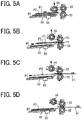
- FIGS. 5A, 5B, 5C, and 5D are schematic diagrams each illustrating an operation of the sheet feeding device 13. Each of FIGS. 5A, 5B, 5C, and 5D illustrates the operation performed when the plurality of sheets P are nipped in the nip region.
- the stacking portion 43 ascends to an appropriate position.
- the controller 70 controls the solenoid 72 to move the pickup roller 54 from the retracted position to the contact position.
- the pickup roller 54 contacts the upper face of the uppermost sheet P1 of the plurality of sheets P stacked on the stacking portion 43. While the pickup roller 54 contacts the upper face of the uppermost sheet P1, the pickup roller 54 starts rotating in the counterclockwise direction. Then, the uppermost sheet P1 and the second sheet P2 placed on the stacking portion 43 are conveyed by the pickup roller 54 toward the nip region formed between the sheet feed roller 53 and the sheet separation roller 55.
- the pickup roller 54 moves to the retracted position again.
- the torque limiter 56 is interlocked and the sheet separation roller 55 starts rotating in the counterclockwise direction.
- the second sheet P2 is conveyed in the direction indicated by black arrow, along with rotation of the sheet separation roller 55, in other words, the lower sheet (second sheet P2) is returned to the stacking portion 43, as illustrated in FIG. 5C .
- the upper sheet (uppermost sheet PI) is conveyed in the direction indicted by white arrow, along with rotation of the sheet feed roller 53, in other words, the upper sheet P1 is conveyed toward the sheet conveyance passage K in the image forming apparatus 1.
- the sheet separation roller 55 When one sheet P is nipped in the nip region after the operation of FIG. 5A , the sheet separation roller 55 does not rotate in the counterclockwise direction as illustrated in FIGS. 5B and 5C , but the uppermost sheet P1 is conveyed in the direction indicted by white arrow while the sheet separation roller 55 is rotated in the clockwise direction, as illustrated in FIG. 5D .
- FIG. 6 is a perspective view of an image forming apparatus having another configuration different from the image forming apparatus 1 of FIG. 1 .
- An image forming apparatus 1A illustrated in FIG. 6 does not include the document reading device 2 and the document conveyance device 10.
- the upper face of the housing of the image forming apparatus 1A functions as the sheet ejection tray 31 that stacks ejected sheets each having an image on the surface.
- the image forming apparatus 1A includes one sheet feeding device 12 while the image forming apparatus 1 of FIG. 1 includes the sheet feeding devices 12 and 13.
- FIG. 7 is a perspective view of the sheet feeding device 12 included in the image forming apparatus 1A of FIG. 6 .
- the sheet feeding device 12 that functions as a drawer device includes a sheet tray 12a and a handle 12b.
- the sheet tray 12a functions as a sheet container and a drawer drawable from to the housing of the image forming apparatus 1A.
- the handle 12b is attached on one side of the sheet tray 12a.
- the sheet tray 12a runs out of sheets, the sheet tray 12a is drawn (detached) from the sheet feeding device 12 to replenish new sheets in the sheet tray 12a.
- the handle 12b As a user grips and pulls the handle 12b, the sheet tray 12a is drawn from the sheet feeding device 12.
- the handle 12b When the sheets are replenished in the sheet tray 12a, the user grips and pushes the handle 12b, so that the sheet tray 12a is pushed into the sheet feeding device 12.
- the sheet tray 12a is drawn (detached) from the sheet feeding device 12 when the sheet tray 12a runs out of sheets while the printing is being performed or when paper jam occurs.
- This operation of drawing the sheet tray 12a is usually performed by a user having instructed the print job of the image.
- the handle 12b of the sheet tray 12a may be gripped by an unspecified number of users. For this reason, if the handle 12b is gripped by a user by the hand on which virus is attached, the virus may be attached to the handle 12b, and contact infection in which virus is infected to another user via the handle 12b may occur.
- an operation assisting tool is used to draw the sheet tray 12a without directly touching the handle 12b of the sheet tray 12a.
- FIGS. 8A, 8B, and 8C are schematic diagrams each illustrating an operation assisting tool 100 according to an embodiment of the present embodiment. Specifically, FIG. 8A is a front view of the operation assisting tool 100, FIG. 8B is a side view of the operation assisting tool 100, and FIG. 8C is a perspective view of the operation assisting tool 100.
- the operation assisting tool 100 is owned by each user using this image forming apparatus.
- the operation assisting tool 100 has an arc portion with the lower portion being opened.
- the inner circumferential surface of the arc portion of the operation assisting tool 100 is an engagement portion 101 that engages with the handle 12b
- the outer circumferential surface of the arc portion of the operation assisting tool 100 is a gripper 102 that is gripped by a user.
- the engagement portion 101 has a first face 101a and a second face 101b each being orthogonal to a drawing direction (moving direction) of the sheet tray 12a. Stoppers 105 in pair are disposed projecting toward each other, at lower portions of the first face 101a and the second face 101b of the engagement portion 101.
- the distance between the stoppers 105 is sufficiently greater than the thickness of the handle 12b.
- a panel operation portion 103 that is used to operate a control panel 200 (see FIG. 11 ) is attached on an upper face 102b of the gripper 102.
- the panel operation portion 103 has a tip portion 103a that functions as a pressing portion.
- the tip portion 103a is made of an elastic material with which a touch screen is operable.
- the panel operation portion 103 is formed by a material different from the body of the operation assisting tool 100.
- the tip portion 103a of the panel operation portion 103 is attached by a known method such as press-fitting, bonding, or screwing. Further, the tip portion 103a of the panel operation portion 103 is attached to the body of the operation assisting tool 100.
- the tip portion 103a of the panel operation portion 103 is easily detached from the body of the operation assisting tool 100. Due to such a structure, the tip portion 103a is preferably replaceable. As the tip portion 103a of the panel operation portion 103 is replaceable, if the tip portion 103a is damaged or broken, the operation assisting tool 100 is continuously used by simply replacing the tip portion 103a.
- the whole panel operation portion 103 may be made of a material different from the body of the operation assisting tool 100.
- the gripper 102 includes a fingertip contact face 102c that contacts the fingertip of a user when the user grips the operation assisting tool 100.
- the operation assisting tool 100 further includes rotation stoppers 104 extending in the vertical direction.
- the rotation stoppers 104 are disposed at both lateral ends (both ends in the width direction) of the upper and lower ends of the fingertip contact face 102c of the gripper 102, to face the side face of the sheet tray 12a of the sheet feeding device 12.
- the rotation stoppers 104 contact a side panel 12c (see FIGS. 9A and 9B ) of the sheet feeding device 12 to stop the operation assisting tool 100 from rotating about the handle 12b.
- the gripper 102 further includes a palm contact face 102a outside the handle 12b.
- the palm contact face 102a of the gripper 102 contacts the palm of a user when the user grips the gripper 102.
- the palm contact face 102a is longer by X mm in the downward direction than the fingertip contact face 102c.
- the operation assisting tool 100 is made of a material that is subjected to antibacterial treatment or a metallic material.
- antibacterial treatment may use a special material in which silver ions are kneaded into a resin or may use any material or treatment having sterilization, disinfection, and antibacterial effects.
- metallic material may include, for example, copper, copper alloy, aluminum, and aluminum alloy safely. Copper and copper alloy are more preferable since these metallic materials have a bactericidal effect.
- the operation assisting tool 100 made of a material that is subjected to antibacterial treatment or a metallic material prevents contact infection of virus via the operation assisting tool 100. Further, since a user grips the gripper 102, the gripper 102 alone may be made of a material that is subjected to antibacterial treatment or a metallic material.
- the engagement portion 101 in the configuration illustrated in FIGS. 8A to 8D is made with the gripper 102 as a single unit.
- the engagement portion 101 and the gripper 102 may be made of different materials.
- the engagement portion 101 may be made of a material appropriate for engagement with the handle 12b and the gripper 102 may be made of a material appropriate for gripping by a user.
- the operability and functionality of the operation assisting tool 100 are enhanced.
- the engagement portion 101 is made of a material having a high friction coefficient such as ethylene propylene diene monomer (EPDM) or silicon rubber, and the friction coefficient of the engagement portion 101 with respect to the handle 12b is set to be higher than the friction coefficient of the gripper 102 with respect to the handle 12b.
- the gripper 102 is made of a material that is subjected to antibacterial treatment or a metallic material, as described above.
- the engagement portion 101 made of a material having a high friction coefficient prevents the operation assisting tool 100 from moving about the handle 12b when operating with the handle 12b. This configuration contributes to preferable pulling and pushing of the sheet tray 12a with respect to the sheet feeding device 12.
- the gripper 102 made of a material that is subjected to antibacterial treatment or a metallic material preferably prevents contact infection of virus via the gripper 102.
- the engagement portion 101 is attached to (the arc portion of) the gripper 102 by a known method such as press-fitting, bonding, or screwing.
- the engagement portion 101 is detachably attached to the gripper 102 (arc portion) by screwing or by press-fitting, so that the engagement portion 101 are replaceable. Since the engagement portion 101 is replaceable, if the engagement portion 101 is damaged or broken, the operation assisting tool 100 is continuously used by simply replacing the engagement portion 101.
- FIGS. 9A and 9B are schematic diagrams each illustrating the operation assisting tool 100 attached to the handle 12b. Specifically, FIG. 9A is a perspective view of the operation assisting tool 100, and FIG. 9B is a cross-sectional view of the operation assisting tool 100.
- the operation assisting tool 100 is attached to the handle 12b by inserting the handle 12b into the engagement portion 101 from above. Since the distance between the stoppers 105 is sufficiently greater than the thickness of the handle 12b, the handle 12b is not caught by the stoppers 105 and is safely inserted into the engagement portion 101 when the operation assisting tool 100 is attached to the handle 12b.
- the first face 101a of the engagement portion 101 comes to face the outer circumferential face 12b1 of the handle 12b and a second face 101b of the engagement portion 101 comes to face the inner circumferential face 12b2 of the handle 12b. Further, the upper face 101c of the engagement portion 101 contacts the upper face of the handle 12b, so that the operation assisting tool 100 is supported by the handle 12b.
- the stoppers 105 formed in pair are located at a position lower than the position of the handle 12b.
- the tip portion of each of the rotation stoppers 104 comes to face the side panel 12c of the sheet feeding device 12.
- the tip portion of the lower rotation stopper 104 contacts the side panel 12c of the sheet feeding device 12, which restricts rotation of the operation assisting tool 100 about the handle 12b.
- the tip portion of the upper rotation stopper 104 contacts the side panel 12c of the sheet feeding device 12, which restricts rotation of the operation assisting tool 100 about the handle 12b.
- the rotation stoppers 104 restrict rotation of the operation assisting tool 100.
- the operation assisting tool 100 is maintained at the position at which the handle 12b is pulled as illustrated in FIG. 9B .
- the operation assisting tool 100 attached to the handle 12b is easily gripped.
- the sheet tray 12a is pulled out without changing the position of the operation assisting tool 100, and the sheet tray 12a is easily drawn (detached) from the sheet feeding device 12.
- FIGS. 10A and 10B are schematic diagrams each illustrating an operation of pulling the sheet tray 12a from the sheet feeding device 12, using the operation assisting tool 100.
- FIG. 10A is a perspective view of pulling the sheet tray 12a using the operation assisting tool 100
- FIG. 10B is a cross-sectional view of pulling the sheet tray 12a using the operation assisting tool 100.
- the user attaches the operation assisting tool 100 that is owned by the user, to the handle 12b.
- the fingertip h1 of the user contacts the fingertip contact face 102c of the gripper 102 and the palm h2 of the user contacts the palm contact face 102a of the gripper 102.
- the operation assisting tool 100 includes a panel operation portion 103 on the upper face 102b of the gripper 102. Due to this configuration, as illustrated in FIG. 10A , the user grips the gripper 102 by nipping the panel operation portion 103 with the fingers of the user. As a result, the operation assisting tool 100 is prevented from moving in the width direction with respect to the hand H of the user, so that the user firmly grips the operation assisting tool 100. As a result, the operability of pulling and pushing the sheet tray 12a with the operation assisting tool 100 are enhanced.
- the palm h2 when the user grips the gripper 102 by the hand H, the palm h2 is at a position lower than the position of the fingertip h1.
- the palm contact face 102a of the gripper 102 where the palm h2 of the user contacts is extended longer by X mm in the downward direction than the fingertip contact face 102c of the gripper 102.
- the contact area where the palm h2 of a user contacts the palm contact face 102a is greater (wider) as compared with a case where the lower end of the palm contact face 102a is at the same position as the lower end of the fingertip contact face 102c.
- the user stably grips the gripper 102 and stably pulls and pushes the sheet tray 12a with the operation assisting tool 100.
- the second face 101b of the engagement portion 101 contacts the inner circumferential face 12b2 of the handle 12b, so that the pulling force of the user is transmitted to the handle 12b via the second face 101b of the engagement portion 101.
- the sheet tray 12a is pulled out from the sheet feeding device 12.
- the second face 101b of the engagement portion 101 comes to face the inner circumferential face 12b2 of the handle 12b. Due to such a configuration, the user does not change the position of the operation assisting tool 100 but grips and pulls the gripper 102, so that the second face 101b of the engagement portion 101 contacts the inner circumferential face 12b2 of the handle 12b.
- each of the stoppers 105 on the second face 101b faces the handle 12b from below.
- force may be generated to rotate the operation assisting tool 100 in the clockwise direction in FIG. 10B when the sheet tray 12a is pulled (detached) from the sheet feeding device 12.
- the stoppers 105 on the second face 101b of the engagement portion 101 contact the lower face of the handle 12b.
- rotation of the operation assisting tool 100 is restricted, so that the operation assisting tool 100 is preferably prevented from coming off from the handle 12b while the sheet tray 12a is being pulled, and the sheet tray 12a is stably drawn (detached) from the sheet feeding device 12.
- the first face 101a of the engagement portion 101 contacts the outer circumferential face 12b1 of the handle 12b, so that the pushing force of the user is transmitted to the handle 12b via the first face 101a of the engagement portion 101. As a result, the sheet tray 12a is pushed (attached) into the sheet feeding device 12.
- the outer circumferential face 12b1 of the handle 12b comes to face the first face 101a of the engagement portion 101. Due to such a configuration, the user does not change the position of the operation assisting tool 100 but grips and pushes the gripper 102, so that the first face 101a of the engagement portion 101 contacts the outer circumferential face 12b1 of the handle 12b.
- each of the stoppers 105 on the first face 101a faces the handle 12b from below.
- force may be generated to rotate the operation assisting tool 100 in the counterclockwise direction in FIG. 10B when the sheet tray 12a is pushed (attached) into the sheet feeding device 12.
- the stoppers 105 on the first face 101a of the engagement portion 101 contact the lower face of the handle 12b.
- the sheet tray 12a As the sheet tray 12a is pushed until the rotation stoppers 104 of the operation assisting tool 100 contact the side panel 12c of the sheet feeding device 12, the sheet tray 12a is automatically inserted into the sheet feeding device 12 due to the configuration of the sheet feeding device 12. As a result, the sheet tray 12a is attached to the sheet feeding device 12, as illustrated in FIG. 10B .
- the operation assisting tool may not include the rotation stoppers 104.
- the sheet tray 12a is pushed to the far end of the sheet feeding device 12 with the operation assisting tool 100, so that the sheet tray 12a is attached to the sheet feeding device 12.
- the rotation stoppers 104 may be elastically deformable to push the sheet tray 12a to the far end of the sheet feeding device 12 using the operation assisting tool 100. As the operation assisting tool 100 is further pushed while the rotation stoppers 104 contact the side panel 12c of the sheet feeding device 12, the rotation stoppers 104 are elastically deformed, so that the sheet tray 12a is pushed to the far end of the sheet feeding device 12.
- the user pulls or pushes the sheet tray 12a without directly touching the handle 12b, and then contact infection of virus via the handle (for example, the handle 12b) of the sheet tray is prevented.
- the operation assisting tool 100 includes the gripper 102 that corresponds to the outer circumferential surface of the arc portion to which the handle 12b is inserted.
- the gripper 102 is made greater than the handle 12b and is easy to grip as compared with the case where the handle 12b is gripped. As a result, the force is applied more easily and the operation with the operation assisting tool 100 is performed stably.
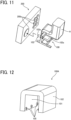
- FIG. 11 is a diagram illustrating the operation of the control panel 200 using the operation assisting tool 100 according to the present embodiment.
- the operation assisting tool 100 is gripped when operating the control panel 200 with the operation assisting tool 100.
- the control panel 200 is operated by pressing any of buttons 200a of the control panel 200 with the tip portion 103a of the panel operation portion 103.
- control panel 200 of the image forming apparatus Since the control panel 200 of the image forming apparatus is touched by an unspecified number of users for setting image quality or setting the number of print sheets, it is highly likely that virus is attached to the control panel 200.
- the control panel 200 is operated by using the operation assisting tool 100 without directly touching the control panel 200. As a result, contact infection via the control panel 200 is prevented.
- FIG. 12 is a perspective view of an operation assisting tool 100A of the modification.
- the operation assisting tool 100A of the modification is made of a soft resinous material such as polypropylene (PP) or a rubber material such as urethane or silicon.
- PP polypropylene
- the operation assisting tool 100A is elastically deformed by the gripping force of the user.
- the operation assisting tool 100A of the modification includes the stoppers 105 at the lower portion of the first face and the second face of the engagement portion.
- the stoppers 105 are disposed at given intervals in the width direction.
- Each of the stoppers 105 have a cylindrical convex shape.
- FIGS. 13A and 13B are diagrams each illustrating the operation assisting tool 100A of the modification, with the operation assisting tool 100A attached to the handle 12b.
- FIG. 13A is a perspective view of the operation assisting tool 100A
- FIG. 13B is a cross-sectional view of the operation assisting tool 100A.
- the operation assisting tool 100A is attached to the handle 12b
- the first face 101a of the engagement portion 101 comes to face the outer circumferential face 12b1 of the handle 12b and the fingertip contact face 102c comes to face the inner circumferential face 12b2 of the handle 12b.
- the second face 101b of the engagement portion 101 contacts the inner circumferential face 12b2 of the handle 12b, so that the sheet tray 12a is pulled (detached) from the sheet feeding device 12.
- the first face 101a of the engagement portion 101 contacts the outer circumferential face 12b1 of the handle 12b, so that the sheet tray 12a is pushed (attached) to the sheet feeding device 12.
- each of the stoppers 105 of the modification faces the lower face of the handle 12b when the sheet tray 12a is pulled out and pushed in the sheet feeding device 12, so that the operation assisting tool 100 is prevented from detached from the handle 12b.
- the gripper 102 is greater in size than the handle 12b, so that the gripper 102 is gripped more easily.
- the user pulls or pushes the sheet tray 12a without directly touching the handle 12b and contact infection of virus via the handle 12b is prevented.
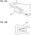
- FIGS. 14A and 14B are diagrams each illustrating the operation assisting tool 100A of the modification, the operation assisting tool 100A gripping a sheet bundle ejected to the sheet ejection tray 31.
- FIG. 14A is a perspective view of the operation assisting tool 100A
- FIG. 14B is a side view of the operation assisting tool 100A.
- the operation assisting tool 100A of the modification elastically deforms by the gripping force of the user. Due to such a configuration, as illustrated in FIGS. 14A and 14B , the operation assisting tool 100A is elastically deformed by the gripping force of the user, so that the sheet bundle ejected to the sheet ejection tray 31 is gripped by the operation assisting tool 100A. According to this configuration, the operation assisting tool 100A allows the user to remove the sheet bundle ejected from the sheet ejection tray 31 without directly touching the sheet bundle.
- the stoppers 105 contact the sheet bundle.
- the stoppers 105 have a plurality of convex shapes. Due to such a configuration, the gripping force of the user is concentrated on the stoppers 105. As a result, the sheet bundle is preferably gripped by the operation assisting tool 100A.
- Each of the stoppers 105 may be made of a material having a friction coefficient higher to the sheet than to the body of the operation assisting tool 100A or a material having a high durability and may be made a material different from the material of the body of the operation assisting tool 100A.
- Each of the stoppers 105 made of a material having a friction coefficient higher to the sheet than to the body of the operation assisting tool 100A prevents the stoppers 105 from sliding and falling from the operation assisting tool 100A due to the weight of the sheet bundle when the operation assisting tool 100A grips the sheet bundle.
- the stoppers 105 are attached to the body of the operation assisting tool 100A by a known method such as press-fitting, bonding, or screwing.
- the stoppers 105 are detachably attached to the body of the operation assisting tool 100A by screwing or by press-fitting, so that the stoppers 105 are replaceable.
- the operation assisting tool 100A is continuously used by simply replacing the stoppers 105.
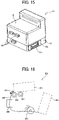
- FIG. 15 is a diagram illustrating the operation assisting tools 100 detachably attached to the image forming apparatus 1A.
- the operation assisting tools 100 are detachably attached to the side face of the image forming apparatus 1A on which the operation assisting tools 100 are used.
- the operation assisting tool 100 is held on the side face of the image forming apparatus 1A by a known method such as press-fitting, adhesion by magnetic force, holding by MAGICTAPE (registered trademark).
- the colors of the plurality of operation assisting tools held on the side face of the image forming apparatus are made different from each other so that the user of each operation assisting tool is easily identified, in other words, distinguished from another user of another operation assisting tool.
- the operation assisting tool is held not inside the housing of the image forming apparatus but on the outside of the image forming apparatus to expose the operation assisting tool.
- sanitization is easily performed by spraying, for example, alcohol when or after the operation assisting tool is used.
- the operation assisting tool is easily attached to or detached from the image forming apparatus.
- the operation assisting tool held on the image forming apparatus is easily recognized visually and avoids an inconvenience to search the place on which the operation assisting tool is held.
- the operation assisting tool is prevented from being lost as compared with the case where the user separately stores the operation assisting tool owned by the user. Further, since the user detaches the operation assisting tool held on the image forming apparatus when using the operation assisting tool, it is prevented that the user returns to the storage in which the operation assisting tool owned by the user is separately stored.
- the operation assisting tool according to the present disclosure is used for the sheet tray 12a of the image forming apparatus 1 but not limited to this configuration.
- the operation assisting tool according to the present disclosure may be used for a device including a drawer.
- FIG. 16 is a schematic diagram illustrating a banknote counter 300 as a device including a drawer.
- the banknote counter 300 includes a stacker 301 and an identification unit 306.
- the stacker 301 functions as a sheet container and a drawer in which banknotes are filled and is drawable from the housing of the banknote counter 300.
- the identification unit 306 identifies the banknotes.
- the banknote counter 300 further includes a collection unit 308 that functions as a sheet container and a drawer and a sheet container to collect and accumulate the distinguished banknotes.
- the collection unit 308 is drawable from the housing of the banknote counter 300.
- a feed roller 302 feeds the banknotes stacked in the stacker 301 to a separation nip region formed between a separation belt 303 and a conveyance roller 304 in contact with each other.
- the separation belt 303 rotates in a direction opposite to the conveyance direction of the banknotes.
- the lowermost banknote alone is conveyed toward the identification unit 306 and the rest of the multiple banknotes are returned by the separation belt 303.
- the plurality of fed banknotes are separated into one banknote.
- the lowermost banknote separated by the separation nip region is conveyed to the identification unit 306.
- the identification unit 306 detects the kind of the banknote, so that the amount of money is added in accordance to the kind of the banknote detected by the identification unit 306.
- a collection wheel 307 is disposed at the distal end of a conveyance passage 305.
- the banknotes conveyed one by one by the collection wheel 307 are accumulated to the collection unit 308.
- a detector that detects banknotes detects that no banknotes are stacked in the stacker 301, conveyance of the banknotes is finished, and the cumulative total of money is displayed on a display of a control panel.
- the handle of the stacker 301 and the handle of the collection unit 308 to be gripped when pulling the stacker 301 or the collection unit 308 from the device is likely to be touched by an unspecified number of users. As a result, it is likely that contact infection occurs via the handle of the stacker 301 and the handle of the collection unit 308. For this reason, by using the above-described operation assisting tool when pulling and pushing the stacker 301 and the collection unit 308, the stacker 301 and the collection unit 308 are pulled out without directly touching the handle of the stacker 301 and the handle of the collection unit 308, and contact infection is prevented.
- an operation assisting tool (for example, the operation assisting tool 100) includes a gripper (for example, the gripper 102), and an engagement portion (for example, the engagement portion 101) to engage with a handle (for example, the handle 12b) of a drawer (for example, the sheet feeding device 12, the sheet tray 12a) drawable from a housing (for example, the housing 1a) of an image forming apparatus (for example, the image forming apparatus 1).
- a gripper for example, the gripper 102
- an engagement portion for example, the engagement portion 101 to engage with a handle (for example, the handle 12b) of a drawer (for example, the sheet feeding device 12, the sheet tray 12a) drawable from a housing (for example, the housing 1a) of an image forming apparatus (for example, the image forming apparatus 1).
- the engagement portion (for example, the engagement portion 101) has a first counter face (for example, the first face 101a) and a second counter face (for example, the second face 101b) to face a pair of faces (for example, the outer circumferential face 12b1, the inner circumferential face 12b2) of the handle (for example, the handle 12b) that are orthogonal to a drawing direction of the drawer (for example, the sheet tray 12a).
- the first counter face of the engagement portion is to face downstream one (for example, the outer circumferential face 12b1) of the pair of faces of the handle in the moving direction
- the second counter face of the engagement portion is to face upstream one (for example, the inner circumferential face 12b2) of the pair of faces of the handle in the moving direction.
- the first counter face such as the first face 101a contacts the handle such as the handle 12b.
- the pulling force of a user is transmitted to the handle to draw out the drawer from the housing of the image forming apparatus.
- the second counter face such as the second face 101b contacts the handle.
- the pushing force of the user is transmitted to the handle to push the drawer into the housing of the image forming apparatus.
- pulling and pushing the drawer with respect to the housing of the image forming apparatus is performed with the operation assisting tool.
- the first counter face (for example, the first face 101a) and the second counter face (for example, the second face 101b) of the engagement portion (for example, the engagement portion 101) are to face the pair of faces orthogonal to the moving direction, with the operation assisting tool (for example, the operation assisting tool 100) being attached to the handle (for example, the handle 12b).
- the user omits (skips) the operation to set the first counter face such as the first face 101a to face the orthogonal face when drawing (pulling) the drawer (for example, the sheet tray 12a) and the operation to set the second counter face such as the second face 101b to face the orthogonal face when pushing the drawer.
- the drawer is pulled out or pushed to the housing (for example, the housing 1a) by gripping and pulling or pushing the operation assisting tool attached to the handle such as the handle 12b.
- the engagement portion (for example, the engagement portion 101) has an opening to which the handle (for example, the handle 12b) is to be inserted.
- the first counter face (for example, the first face 101a) has a first protrusion (for example, the stoppers 105) protruding toward the second counter face (for example, the second face 101b).
- the second counter face has a second protrusion (for example, the stoppers 105) protruding toward the first counter face.
- Each of the first protrusion and the second protrusion is disposed at a position lower than a position at which the handle is to be inserted to the opening.
- the operation assisting tool such as the operation assisting tool 100 is prevented from coming off from the handle such as the handle 12b while the drawer (for example, the sheet tray 12a) is pulled or pushed with the operation assisting tool.
- the operation assisting tool (for example, the operation assisting tool 100) further includes a rotation stopper (for example, the rotation stopper 104) to prevent rotation of the operation assisting tool while the operation assisting tool is attached to the handle (for example, the handle 12b) of the drawer (for example, the sheet tray 12a).
- a rotation stopper for example, the rotation stopper 104 to prevent rotation of the operation assisting tool while the operation assisting tool is attached to the handle (for example, the handle 12b) of the drawer (for example, the sheet tray 12a).
- the operation assisting tool attached to the handle such as the handle 12b is prevented from rotating about the handle, and the operation assisting tool is maintained at the position for the pulling operation to pull out the drawer.
- the operation assisting tool attached to the handle is easily grasped.
- the drawer is drawn (detached) without changing the position of the operation assisting tool, and the drawer is pulled out easily.
- the gripper (for example, the gripper 102) has a palm contact face (for example, the palm contact face 102a) on which the palm (for example, the palm h2) of a user contacts when the user grips the gripper and a fingertip contact face (for example, the fingertip contact face 102c) on which a fingertip (for example, the fingertip h1) of the user contacts when the user grips the gripper.
- the length of the palm contact face is longer in a vertical direction than a length of the finger contact face.
- the gripper such as the gripper 102 is stably gripped, and the drawer (for example, the sheet tray 12a) is pulled out from and pushed into the housing (for example, the housing 1a) of the image forming apparatus (for example, the image forming apparatus 1) stably with the operation assisting tool.
- the operation assisting tool (for example, the operation assisting tool 100) further includes a panel operation portion (panel operation portion 103) to operate a control panel (control panel 200) provided for the image forming apparatus (for example, the image forming apparatus 1).
- the operation assisting tool allows the user to operate without directly contacting the control panel (for example, the control panel 200), which prevents contact infection via the control panel.
- the panel operation portion (for example, the panel operation portion 103) is attached to the gripper (for example, the gripper 102).
- the user nips the panel operation portion such as the panel operation portion 103 with the fingers to grip the gripper such as the gripper 102, which allows the user to grip the operation assisting tool (for example, the operation assisting tool 100) reliably.
- the operation assisting tool for example, the operation assisting tool 100
- the operability using the operation assisting tool is enhanced for pulling and pushing the drawer (for example, the sheet tray 12a).
- the panel operation portion (for example, the panel operation portion 103) has a replaceable pressing portion (for example, the tip portion 103a) to press the control panel (for example, the control panel 200).
- the operation assisting tool (for example, the operation assisting tool 100) is continuously used by simply replacing the pressing portion.
- the pressing portion (for example, the tip portion 103a) that presses at least the control panel (for example, the control panel 200) of the panel operation portion (for example, the panel operation portion 103) is formed by a material different from a body (for example, the gripper 102) of the operation assisting tool (for example, the operation assisting tool 100).
- At least the pressing portion such as the tip portion 103a of the panel operation portion such as the panel operation portion 103 is made of a material that achieves easy operation of the control panel.
- the pressing portion is made of a material that allows the user to smoothly grip the body of the operation assisting tool.
- the engagement portion (for example, the engagement portion 101) is replaceable.
- the operation assisting tool for example, the operation assisting tool 100
- the engagement portion such as the engagement portion 101
- the operation assisting tool for example, the operation assisting tool 100
- the engagement portion (for example, the engagement portion 101) is formed by a material different from a body (for example, the gripper 102) of the operation assisting tool (for example, the operation assisting tool 100).
- the engagement portion such as the engagement portion 101 is made of a material that is suitable for engagement with the handle (for example, the handle 12b), and the gripper such as the gripper 102 is made of a material that is suitable for gripping by the user.
- a coefficient of friction of the engagement portion (for example, the engagement portion 101) on the handle (for example, the handle 12b) is greater than a coefficient of friction of the body on the handle.
- the operation assisting tool (for example, the operation assisting tool 100) is prevented from moving with respect to the handle such as the handle 12b when the engagement portion such as the engagement portion 101 contacts the handle to pull and push the drawer (for example, the sheet tray 12a).
- the pulling operation and the pushing operation of the drawer are performed favorably.
- At least the gripper (for example, the gripper 102) is subjected to antibacterial treatment.
- contact infection via the operation assisting tool (for example, the operation assisting tool 100) is preferably prevented.
- At least the gripper (for example, the gripper 102) includes metal.
- contact infection via the operation assisting tool (for example, the operation assisting tool 100) is preferably prevented.
- the engagement portion (for example, the engagement portion 101) corresponds to an inner circumferential face of an arc portion to which the handle (for example, the handle 12b) is to be inserted
- the gripper (for example, the gripper 102) corresponds to an outer circumferential face of the arc portion
- the arc portion is deformable.
- the operation assisting tool (for example, the operation assisting tool 100) is flexibly deformed for the user to grip, for example, a sheet bundle ejected from the image forming apparatus (for example, the image forming apparatus 1), and the sheet bundle is removed from the sheet ejection tray (for example, the sheet ejection tray 31) without directly contacting the sheet bundle by the operation assisting tool.
- the operation assisting tool (for example, the operation assisting tool 100) further includes a protrusion (for example, the stoppers 105) disposed at a lower end of the inner circumferential face of the arc portion.
- the protrusion faces the handle (for example, the handle 12b), so that the operation assisting tool is prevented from detached from the handle when the drawer (for example, the sheet tray 12a) is pulled out or pushed into the image forming apparatus (such as the image forming apparatus 1). Further, when a sheet bundle is gripped, the protrusion contacts the sheet bundle to grip with a relatively high contact pressure.
- the operation assisting tool for example, the operation assisting tool 100
- the operation assisting tool 100 is continuously used by simply replacing the protrusion.
- the protrusion (for example, the stoppers 105) is formed by a material different from the arc portion.
- the protrusion such as the stoppers 105 is made of a material that favorably nip the sheet bundle by the operation assisting tool (for example, the operation assisting tool 100), and the arc portion is formed of a material that is easily gripped by the user.
- the operation assisting tool for example, the operation assisting tool 100
- the arc portion is formed of a material that is easily gripped by the user.
- the operation assisting tool (for example, the operation assisting tool 100) is detachably attached to the housing (for example, the housing 1a) of the image forming apparatus (for example, the image forming apparatus 1).
- the operation assisting tool is prevented from being lost as compared with the case where the user separately stores the operation assisting tool. Further, since the user detaches the operation assisting tool held by the housing of the image forming apparatus when using the operation assisting tool, it is prevented that the user returns to the storage in which each operation assisting tool is separately stored.
- the handle (for example, the handle 12b) is a handle of the sheet container (for example, the sheet tray 12a) to contain sheets.
- an image forming apparatus (for example, the image forming apparatus 1) including a housing (for example, the housing 1a), a drawer (for example, the sheet feeding device 12, the sheet tray 12a) drawable from the housing, and the operation assisting tool (for example, the operation assisting tool 100) of any one of Modes 1 to 21.
- a housing for example, the housing 1a
- a drawer for example, the sheet feeding device 12, the sheet tray 12a
- the operation assisting tool for example, the operation assisting tool 100 of any one of Modes 1 to 21.
- Mode 23 according to Mode 22, the operation assisting tool (for example, the operation assisting tool 100) is held on a portion visible from an outside of the image forming apparatus (for example, the image forming apparatus 1).
- the operation assisting tool held by the image forming apparatus is found easily.
- a plurality of operation assisting tools (for example, the plurality of operation assisting tools 100) including the operation assisting tool (for example, the operation assisting tool 100) is held on the image forming apparatus (for example, the image forming apparatus 1).
- the plurality of operation assisting tools for a plurality of users is held by the image forming apparatus.
- the plurality of operation assisting tools (for example, the plurality of operation assisting tools 100) has different colors from each other.
- the operation assisting tool of a user is distinguished from the operation assisting tool of another user, from the plurality of operation assisting tools held by the image forming apparatus (for example, the image forming apparatus 1).
- the drawer (for example, the sheet tray 12a) includes a sheet tray.
Landscapes
- Physics & Mathematics (AREA)
- General Physics & Mathematics (AREA)
- Engineering & Computer Science (AREA)
- Computer Vision & Pattern Recognition (AREA)
- Sheets, Magazines, And Separation Thereof (AREA)
- Paper Feeding For Electrophotography (AREA)
Abstract
Description
- Embodiments of the present disclosure relate to an operation assisting tool and an image forming apparatus including the operation assisting tool.
- Various types of image forming apparatuses are known in the art to include a drawer unit that is drawable from the housing of an image forming apparatus.
-
Japanese Unexamined Patent Application Publication No. 2021-080090 - The handle of the sheet tray as a drawer is a part touched by the hand of an unspecified number of users. For this reason, if the handle is touched by the hand with virus being adhered, infection of virus may spread through the handle.
- In view of the above-described disadvantages, an object of the present disclosure is to provide an operation assisting tool that prevents spreading of virus infection via the handle of a component of an image forming apparatus including such an operation assisting tool.
- Embodiments of the present disclosure described herein provide a novel operation assisting tool including a gripper and an engagement portion to engage with a handle of a drawer drawable from a housing of an image forming apparatus.
- Further, embodiments of the present disclosure described herein provide an image forming apparatus including a housing, a drawer drawable from the housing, and the above-described operation assisting tool.
- According to the present disclosure, an operation assisting tool prevents spreading of virus infection via the handle of a component of an image forming apparatus including such an operation assisting tool.
- Exemplary embodiments of this disclosure will be described in detail based on the following figures, wherein:
-
FIG. 1 is a schematic diagram illustrating a configuration of an image forming apparatus according to an embodiment of the present disclosure; -
FIG. 2 is a schematic diagram illustrating a configuration of a sheet feeding device; -
FIG. 3 is a schematic diagram illustrating a configuration of a driving mechanism of the sheet feeding device; -
FIGS. 4A and 4B are schematic diagrams, each illustrating an operation of a contact-separation mechanism of a pickup roller in the sheet feeding device; -
FIGS. 5A, 5B, 5C, and 5D are schematic diagrams, each illustrating an operation of the sheet feeding device; -
FIG. 6 is a perspective view of an image forming apparatus having a configuration different from the image forming apparatus ofFIG. 1 ; -
FIG. 7 is a perspective view of a sheet feeding device included in the image forming apparatus ofFIG. 6 ; -
FIGS. 8A, 8B, and 8C are schematic diagrams, each illustrating an operation assisting tool according to an embodiment of the present embodiment; -
FIGS. 9A and 9B are schematic diagrams, each illustrating the operation assisting tool attached to a handle; -
FIGS. 10A and 10B are schematic diagrams, each illustrating an operation of pulling a sheet tray from the sheet feeding device, using the operation assisting tool; -
FIG. 11 is a diagram illustrating operation of a control panel using the operation assisting tool according to the present embodiment; -
FIG. 12 is a perspective view of the operation assisting tool of a modification; -
FIGS. 13A and 13B are diagrams, each illustrating the operation assisting tool of the modification attached to the handle; -
FIGS. 14A and 14B are diagrams, each illustrating the operation assisting tool of the modification gripping a bundle of sheets ejected to a sheet ejection tray; -
FIG. 15 is a diagram illustrating the operation assisting tool detachably attached to the image forming apparatus; and -
FIG. 16 is a diagram illustrating a schematic configuration of a banknote counter. - The accompanying drawings are intended to depict embodiments of the present disclosure and should not be interpreted to limit the scope thereof. The accompanying drawings are not to be considered as drawn to scale unless explicitly noted.
- It will be understood that if an element or layer is referred to as being "on," "against," "connected to" or "coupled to" another element or layer, then it can be directly on, against, connected or coupled to the other element or layer, or intervening elements or layers may be present. In contrast, if an element is referred to as being "directly on," "directly connected to" or "directly coupled to" another element or layer, then there are no intervening elements or layers present. Like numbers referred to like elements throughout. As used herein, the term "and/or" includes any and all combinations of one or more of the associated listed items.
- Spatially relative terms, such as "beneath," "below," "lower," "above," "upper" and the like may be used herein for ease of description to describe one element or feature's relationship to another element(s) or feature(s) as illustrated in the figures. It will be understood that the spatially relative terms are intended to encompass different orientations of the device in use or operation in addition to the orientation depicted in the figures. For example, if the device in the figures is turned over, elements describes as "below" or "beneath" other elements or features would then be oriented "above" the other elements or features. Thus, term such as "below" can encompass both an orientation of above and below. The device may be otherwise oriented (rotated 90 degrees or at other orientations) and the spatially relative descriptors herein interpreted accordingly.
- The terminology used herein is for describing particular embodiments and examples and is not intended to be limiting of exemplary embodiments of this disclosure. As used herein, the singular forms "a," "an," and "the" are intended to include the plural forms as well, unless the context clearly indicates otherwise. It will be further understood that the terms "includes" and/or "including," when used in this specification, specify the presence of stated features, integers, steps, operations, elements, and/or components, but do not preclude the presence or addition of one or more other features, integers, steps, operations, elements, components, and/or groups thereof.
- Referring now to the drawings, embodiments of the present disclosure are described below. In the drawings for explaining the following embodiments, the same reference codes are allocated to elements (members or components) having the same function or shape and redundant descriptions thereof are omitted below.
- Next, a description is given of a configuration and functions of an operation assisting tool and an image forming apparatus incorporating the operation assisting tool, according to an embodiment of the present disclosure, with reference to drawings. Note that identical parts or equivalents are given identical reference numerals and redundant descriptions are summarized or omitted accordingly.
- Referring now to
FIG. 1 , a description is given of an overall configuration and operations of animage forming apparatus 1 according to an embodiment of the present disclosure. -
FIG. 1 is a schematic diagram illustrating a configuration of an image forming apparatus according to an embodiment of the present disclosure. - In
FIG. 1 , theimage forming apparatus 1 includes adocument reading device 2, anexposure device 3, animage forming device 4, aphotoconductor drum 5, a transfer device 7, adocument conveyance device 10,sheet feeding devices sheet feeding device 16, aregistration roller pair 17, afixing device 20, afixing roller 21, apressure roller 22, and asheet ejection tray 31. Thedocument reading device 2 optically reads image data of an original document D. Theexposure device 3 emits an exposure light L based on the image data read by thedocument reading device 2 to irradiate the exposure light L onto a surface of thephotoconductor drum 5 that functions as an image bearer. Theimage forming device 4 forms a toner image on the surface of thephotoconductor drum 5. The transfer device 7 transfers the toner image formed on the surface of thephotoconductor drum 5 onto a sheet P serving as a recording medium. - The
document conveyance device 10 corresponding to an automatic document feeder (ADF) conveys the original document D set in thedocument conveyance device 10 to thedocument reading device 2. Thesheet feeding device 12 feeds sheets P accommodated in asheet tray 12a, and thesheet feeding device 13 feeds sheets P stored in asheet tray 13a. The bypasssheet feeding device 16 feeds sheets P that is manually set by a user. - The
registration roller pair 17 serving as a conveyance roller pair conveys the sheet P toward the transfer device 7. The fixingdevice 20 fixes a toner image (unfixed image) borne on the on the sheet P to the sheet P. The fixingdevice 20 includes the fixingroller 21 and thepressure roller 22. Thesheet ejection tray 31 stacks the sheets P ejected from the housing of theimage forming apparatus 1. - The
sheet feeding device 12 includes a stacking portion (elevation plate) 42 that is movable in the vertical direction, and asheet feeding mechanism 52 serving as a sheet feeder. Thesheet feeding device 13 includes a stacking portion (elevation plate) 43 that is movable in the vertical direction, and asheet feeding mechanism 52 serving as a sheet feeder. - With reference to
FIG. 1 , a description is given of a basic image forming operation of theimage forming apparatus 1. - The original document D is conveyed (fed) by conveyance rollers of the
document conveyance device 10 from the document loading table in a direction indicated by arrow inFIG. 1 , and then passes over thedocument reading device 2. While the original document D is passing over thedocument reading device 2, thedocument reading device 2 optically reads image data of the original document D passing over thedocument reading device 2. - The image data optically scanned by the
document reading device 2 is converted into electrical signals. The electrical signals are then transmitted to theexposure device 3 serving as an optical writer. Theexposure device 3 emits exposure light (laser light) L based on the image data of the electrical signals, toward the surface of thephotoconductor drum 5 of theimage forming device 4. - Meanwhile, while the
photoconductor drum 5 rotates in a clockwise direction inFIG. 1 , theimage forming device 4 performs a predetermined series of image forming processes, such as a charging process, an exposing process, and a developing process, to form a toner image corresponding to the image data on thephotoconductor drum 5. Thereafter, the toner image formed on the surface of thephotoconductor drum 5 is transferred by the transfer device 7 serving as an image forming portion, onto the sheet P conveyed by theregistration roller pair 17. - Now, a description is given of how the sheet P is conveyed to the transfer device 7 (image forming portion).
- First, one of the
sheet feeding devices housing 1a of theimage forming apparatus 1 is selected automatically or manually. For example, the lowersheet feeding device 13 is selected. Then, thesheet feeding mechanism 52 feeds the uppermost sheet P of the sheets P accommodated in thesheet feeding device 13, toward a sheet conveyance passage K. The uppermost sheet P (hereinafter, simply the sheet P) passes through the sheet conveyance passage K, in which multiple sheet conveyance rollers including asheet conveyance roller 59 are disposed, and then reaches theregistration roller pair 17. When the sheet P reaches theregistration roller pair 17, theregistration roller pair 17 is stopped rotating. As the leading end of the sheet P contacts the nip region formed by the rollers of theregistration roller pair 17, skew of the sheet P is corrected. - When the bypass
sheet feeding device 16 that is disposed on one side of theimage forming apparatus 1 is selected, the sheet P placed by a user on the bypass tray of the bypasssheet feeding device 16 is conveyed by the sheet feeding mechanism 52 (sheet feeder) toward the sheet conveyance passage K. When a plurality of sheets P are placed on the bypass tray of the bypasssheet feeding device 16, the uppermost sheet P is conveyed toward the sheet conveyance passage K. Then, when the sheet P reaches theregistration roller pair 17, skew of the sheet P is corrected. Thereafter, theregistration roller pair 17 starts rotating again, and the sheet P is then conveyed toward the transfer device 7 (image forming portion) in synchrony with movement of the toner image formed on the surface of thephotoconductor drum 5 for forming the toner image on the sheet P at the correct position. - As described above, the
registration roller pair 17 functions as a conveyance roller pair that corrects the skew of the sheet P as the leading end of the sheet P contacts the nip region between the rollers of theregistration roller pair 17 while stopped, and then holds and conveys the deskewed sheet P in the nip region while theregistration roller pair 17 is rotating. After the transfer device 7 transfers the toner image from thephotoconductor drum 5 onto the sheet P in the transfer process, the sheet P is conveyed to the fixingdevice 20 along the sheet conveyance passage K. In the fixingdevice 20, the sheet P is conveyed between the fixingroller 21 and thepressure roller 22, so that the toner image is fixed to the sheet P by heat applied by the fixingroller 21 and pressure applied by the fixingroller 21 and thepressure roller 22, in the fixing process. - After the toner image is fixed to the sheet P in the fixing process, the sheet P passes a fixing nip region formed between the fixing
roller 21 and thepressure roller 22. Then, the sheet P is ejected from theimage forming apparatus 1 to be stacked as an output image on thesheet ejection tray 31. Thus, a series of the image forming processes is completed. - Next, a detailed description is given of the sheet feeding device according to the present embodiment.
- Note that a description is given of the lower
sheet feeding device 13 among the plurality of sheet feeding devices, i.e., thesheet feeding devices image forming apparatus 1. However, since the uppersheet feeding device 12 has the substantially same structure as the lowersheet feeding device 13 except the respective positions. For this reason, the description of the uppersheet feeding device 12 is omitted. -
FIG. 2 is a schematic diagram illustrating a configuration of thesheet feeding device 13. - The
sheet feeding device 13 includes a stacking portion 43 (elevation plate), and asheet feeding mechanism 52. The stackingportion 43 stacks a plurality of sheets P. Thesheet feeding mechanism 52 that functions as a sheet feeder feeds the sheets P stacked on the stackingportion 43. The stackingportion 43 rotates about arotational center shaft 43a (seeFIG. 1 ) in the normal and reverse directions to move in the vertical direction. - The
sheet feeding mechanism 52 includes asheet feed roller 53, apickup roller 54, asheet separation roller 55 that functions as a separator, atorque limiter 56, and a direct current (DC) motor 77 that functions as a drive source. Thesheet feeding mechanism 52 further includes a contact-separation mechanism and a movingmechanism 80. The contact-separation mechanism brings thepickup roller 54 to contact or separate from the sheet P (uppermost sheet PI) stacked on the stackingportion 43. The movingmechanism 80 moves thesheet separation roller 55 in the width direction of the sheet P. The width direction of the sheet P is orthogonal to the sheet conveyance direction and the drawing sheet ofFIG. 2 . - The
sheet feed roller 53 is disposed near the leading end of the sheets P stacked on the stackingportion 43 in the sheet conveyance direction (direction indicted by white arrow inFIG. 2 ). Thesheet feed roller 53 rotates (in the counterclockwise direction inFIG. 2 ) along the sheet conveyance direction while contacting the upper face of the uppermost sheet P of the sheets P on the stackingportion 43, so that the sheet P is conveyed in the sheet conveyance direction indicated by the broken arrow inFIG. 2 . - The
pickup roller 54 rotates in the counterclockwise direction inFIG. 2 along the sheet conveyance direction while contacting the upper face of the uppermost sheet P stacked on the stackingportion 43, so that the sheet P is conveyed toward thesheet feed roller 53. Thepickup roller 54 is capable of contacting and separating from the sheet P (uppermost sheet PI) stacked on the stackingportion 43. In other words, thepickup roller 54 is movable between a retracted position at which thepickup roller 54 does not contact the sheet P stacked on the stacking portion 43 (seeFIG. 4B ) and a contact position at which thepickup roller 54 contacts the sheet P as illustrated inFIG. 2 . - The
sheet separation roller 55 is disposed to form a nip region with thesheet feed roller 53. Thesheet separation roller 55 functions as a separator that separates the sheets P (for example, the sheet P2) below the uppermost sheet P1 from the uppermost sheet P1, so that the uppermost sheet P1 alone is fed when a plurality of sheets P is nipped in the nip region formed between thesheet separation roller 55 and thesheet feed roller 53. - Specifically, when one sheet P is nipped in the nip region formed by the
sheet separation roller 55 serving as a separator and thesheet feed roller 53, thesheet separation roller 55 rotates in the sheet conveyance direction, in other words, rotates in the clockwise direction indicated by a broken arrow inFIG. 2 . When a plurality of sheets P are nipped in the nip region formed by thesheet separation roller 55 serving as a separator and thesheet feed roller 53, thesheet separation roller 55 rotates in the direction opposite to the sheet conveyance direction, in other words, rotates in the counterclockwise direction indicated by a solid arrow inFIG. 2 . As a result, the uppermost sheet P1 of the plurality of sheets P is conveyed in the sheet conveyance direction along with the rotation of thesheet feed roller 53 while the second sheet P2 below the uppermost sheet P1 is conveyed in the direction opposite the sheet conveyance direction. - Each of the
sheet feed roller 53, thepickup roller 54, and thesheet separation roller 55 has a roller portion including rubber material (or resin material) on the shaft, and the roller portion is a single unit or divided portions aligned along the axial direction of the shaft. Further, each roller portion of thesheet feed roller 53, thepickup roller 54, and thesheet separation roller 55 is detachably attachable (replaceable) to the shaft of each of thesheet feed roller 53, thepickup roller 54, and thesheet separation roller 55, so that maintenance of the roller portion is easily performed. - The
DC motor 77 functioning as a drive source is feedback-controlled so that the rotational speed of the motor shaft is to be a predetermined value. Specifically, thecontroller 70 performs the pulse width modulation (PWM) control to adjust the current (or voltage) applied to theDC motor 77, so that the number of rotations of theDC motor 77 remains constant regardless of the load variation influence. To be more specific, when a relatively large amount of load is applied on theDC motor 77, thecontroller 70 adjusts to apply a relatively large amount of current (or voltage) to theDC motor 77. When a relatively small amount of load is applied on theDC motor 77, thecontroller 70 adjusts to apply a relatively small amount of current (or voltage) to theDC motor 77. Thus, theDC motor 77 achieves the constant number of rotations. - In the
sheet feeding device 13, the stackingportion 43 moves in the vertical direction depending on the number of sheets P stacked on the stackingportion 43 so that thepickup roller 54 contacts the uppermost sheet P1 placed on top of the sheets P stacked on the stackingportion 43. Then, the sheet feeding operation of the sheets P starts after thepickup roller 54 is lowered to a position where thepickup roller 54 contacts the upper face of the uppermost sheet P1 on the sheets P stacked on the stackingportion 43 that is located at the vertically adjusted position. - An inlet guide plate is disposed between the stacking
portion 43 and the nip region formed between thesheet feed roller 53 and thesheet separation roller 55. Thesheet feeding device 13 includes side fences that restrict the position in the width direction of the sheet P stacked on the stackingportion 43. The width direction is a direction orthogonal to the drawing sheet ofFIG. 2 . The side fences of thesheet feeding device 13 are disposed at both lateral ends, in other words, at both ends in the width direction of the sheet P, so that the side fences sandwich the sheet P. Due to such a configuration, a manual movement mechanism such as the side fences moves the sheet P in the width direction in accordance with the lateral length of the sheet P. - The
sheet feeding device 13 includes an end fence that restricts the position of the sheet P stacked on the stackingportion 43, in the sheet conveyance direction. The sheet conveyance direction is left and right directions inFIG. 2 . The end fence of thesheet feeding device 13 is disposed to contact the trailing end of the sheet P in the sheet conveyance direction. Due to such a configuration, the manual movement mechanism such as the end fence moves the sheet P in the sheet conveyance direction in accordance with the longitudinal length of the sheet P. -
FIG. 3 is a schematic diagram illustrating a driving mechanism of thesheet feeding device 13. - As illustrated in
FIG. 3 , thesheet feed roller 53 includes a two-step gear 65 having anupper gear 65a and alower gear 65b. The two-step gear 65 is mounted on the shaft of thesheet feed roller 53. Theupper gear 65a of the two-step gear 65 meshes with asecond gear 62c of a two-step pulley gear 62. Thelower gear 65b of the two-step gear 65 meshes with anidler gear 67. Theidler gear 67 meshes with agear 68 mounted on the shaft of thepickup roller 54. - A
first gear 62b of the two-step pulley gear 62 meshes with aseparation gear 69 mounted on the shaft of thesheet separation roller 55. Atorque limiter 56 is mounted on the shaft of thesheet separation roller 55. Amotor pulley 60 is attached to the DC motor 77 (drive motor). Atiming belt 61 is wound with tension around themotor pulley 60 and apulley 62a of the two-step pulley gear 62. - The driving force is transmitted from the
DC motor 77 to theseparation gear 69 via themotor pulley 60, thetiming belt 61, thepulley 62a and thefirst gear 62b. The driving force from theseparation gear 69 is transmitted to or interrupted by thesheet separation roller 55 via thetorque limiter 56. - When the running torque (rotational load) exceeding the predetermined value is applied to the
sheet separation roller 55, thesheet separation roller 55 idles relative to thetorque limiter 56. When one sheet P or no sheet is nipped in the nip region (contact portion) formed between thesheet feed roller 53 and thesheet separation roller 55, the rotational load applied to thesheet separation roller 55 is relatively large. In order to adjust the rotational load, thetorque limiter 56 interrupts drive transmission from theDC motor 77 to thesheet separation roller 55. For this reason, thesheet separation roller 55 idles relative to thetorque limiter 56 and is rotated along with rotation of thesheet feed roller 53 in the clockwise direction inFIG. 3 . - When a plurality of sheets P is nipped in the nip region, the rotational load applied to the
sheet separation roller 55 is relatively small due to slippage of the sheets P. For this reason, thetorque limiter 56 transmits the driving force from theDC motor 77 to thesheet separation roller 55. As a result, thesheet separation roller 55 rotates in the counterclockwise direction inFIG. 3 . By so doing, the sheets P of the plurality of sheets nipped in the nip region below the uppermost sheet P1 are conveyed in the direction opposite the sheet conveyance direction to return to the stackingportion 43. Due to such a configuration, one sheet P is fed in the sheet feeding direction (sheet conveyance direction) without causing multifeeding error in which multiple sheets P are fed from the nip region formed between thesheet feed roller 53 and thesheet separation roller 55. - The driving force transmitted from the
DC motor 77 to the two-step pulley gear 62 is further transmitted to theupper gear 65a of the two-step gear 65 via thesecond gear 62c, so that thesheet feed roller 53 is driven and rotated in the counterclockwise direction inFIG. 3 . Further, the driving force is transmitted to thegear 68 via thelower gear 65b of the two-step gear 65 and theidler gear 67, so that thepickup roller 54 is driven and rotated in the counterclockwise direction inFIG. 3 . -
FIGS. 4A and 4B are schematic diagrams each illustrating an operation of a contact-separation mechanism of thepickup roller 54 in thesheet feeding device 13. - The
pickup roller 54 is rotatably held by anarm 58. Thearm 58 is rotatably held by the rotary shaft of thesheet feed roller 53. Aspring 73 and asolenoid 72 are coupled to aprotrusion 58a of thearm 58. Thespring 73 biases so that thepickup roller 54 moves to the retracted position. Thesolenoid 72 moves thepickup roller 54 to the contact position against the biasing force of thespring 73. - As the controller 70 (see
FIG. 2 ) turns on thesolenoid 72, thepickup roller 54 moves to the contact position as illustrated inFIG. 4A . When thecontroller 70 turns off thesolenoid 72, thepickup roller 54 moves to the retracted position as illustrated inFIG. 4B . Note that theidler gear 67 described above with reference toFIG. 3 is disposed on thearm 58, and then rotates together with thearm 58 while maintaining the meshing with thegear 68 of thepickup roller 54 and the meshing state with thelower gear 65b of thesheet feed roller 53. - When the sheet P is not set on the stacking
portion 43, anend detection sensor 95 detects the state. In response to the detection, the controller 70 (seeFIG. 2 ) controls thesolenoid 72 to move thepickup roller 54 to the retracted position (seeFIG. 4B ). When the sheet P is set on the stackingportion 43, theend detection sensor 95 detects the state. In response to the detection, thecontroller 70 controls thesolenoid 72 to move thepickup roller 54 from the retracted position toward the contact position (seeFIG. 4A ). - Then, the
pickup roller 54 starts to rotate in the counterclockwise direction while thepickup roller 54 is in contact with the upper face of the uppermost sheet P1 of the sheets P stacked on the stackingportion 43. In synchrony with this movement, thesheet feed roller 53 and thesheet separation roller 55 start to rotate. As a result, the uppermost sheet P1 of the sheets P stacked on the stackingportion 43 is fed by thepickup roller 54 to be conveyed toward the nip region between thesheet feed roller 53 and thesheet separation roller 55. Further, one sheet P is separated and conveyed from the nip region toward theimage forming device 4. - When the sheets P stacked on the stacking
portion 43 are totally conveyed and no sheet is left on the stackingportion 43, the state of the stackingportion 43 is detected by theend detection sensor 95. When theend detection sensor 95 detects that no sheet is set on the stackingportion 43, thecontroller 70 controls thesolenoid 72 to move thepickup roller 54 to the retracted position again (seeFIG. 4B ). -
FIGS. 5A, 5B, 5C, and 5D are schematic diagrams each illustrating an operation of thesheet feeding device 13. Each ofFIGS. 5A, 5B, 5C, and 5D illustrates the operation performed when the plurality of sheets P are nipped in the nip region. - First, as illustrated in
FIG. 5A , when the sheets P are set on the stackingportion 43, the stackingportion 43 ascends to an appropriate position. Then, the controller 70 (seeFIG. 2 ) controls thesolenoid 72 to move thepickup roller 54 from the retracted position to the contact position. Then, thepickup roller 54 contacts the upper face of the uppermost sheet P1 of the plurality of sheets P stacked on the stackingportion 43. While thepickup roller 54 contacts the upper face of the uppermost sheet P1, thepickup roller 54 starts rotating in the counterclockwise direction. Then, the uppermost sheet P1 and the second sheet P2 placed on the stackingportion 43 are conveyed by thepickup roller 54 toward the nip region formed between thesheet feed roller 53 and thesheet separation roller 55. Now, a description is given of a case when the uppermost sheet P1 and the second sheet P2 are fed together (multiple feeding). When the uppermost sheet P1 and the second sheet P2 are not nipped in the nip region, thetorque limiter 56 idles and thesheet separation roller 55 rotates in the clockwise direction. - As illustrated in
FIG. 5B , when the uppermost sheet P1 and the second sheet P2 fed together are conveyed to the nip region (multiple feeding), thepickup roller 54 moves to the retracted position again. As the uppermost sheet P1 and the second sheet P2 are nipped in the nip region, thetorque limiter 56 is interlocked and thesheet separation roller 55 starts rotating in the counterclockwise direction. As thesheet separation roller 55 rotates in the counterclockwise direction, the second sheet P2 is conveyed in the direction indicated by black arrow, along with rotation of thesheet separation roller 55, in other words, the lower sheet (second sheet P2) is returned to the stackingportion 43, as illustrated inFIG. 5C . The upper sheet (uppermost sheet PI) is conveyed in the direction indicted by white arrow, along with rotation of thesheet feed roller 53, in other words, the upper sheet P1 is conveyed toward the sheet conveyance passage K in theimage forming apparatus 1. - As illustrated in
FIG. 5D , after thesheet separation roller 55 returns the lower sheet (second sheet) P2 toward the stackingportion 43, the lower sheet P2 passes through the nip region. Then, thetorque limiter 56 idles again, and thesheet separation roller 55 rotates in the clockwise direction again. - When one sheet P is nipped in the nip region after the operation of
FIG. 5A , thesheet separation roller 55 does not rotate in the counterclockwise direction as illustrated inFIGS. 5B and 5C , but the uppermost sheet P1 is conveyed in the direction indicted by white arrow while thesheet separation roller 55 is rotated in the clockwise direction, as illustrated inFIG. 5D . -
FIG. 6 is a perspective view of an image forming apparatus having another configuration different from theimage forming apparatus 1 ofFIG. 1 . - An
image forming apparatus 1A illustrated inFIG. 6 does not include thedocument reading device 2 and thedocument conveyance device 10. The upper face of the housing of theimage forming apparatus 1A functions as thesheet ejection tray 31 that stacks ejected sheets each having an image on the surface. Moreover, theimage forming apparatus 1A includes onesheet feeding device 12 while theimage forming apparatus 1 ofFIG. 1 includes thesheet feeding devices -
FIG. 7 is a perspective view of thesheet feeding device 12 included in theimage forming apparatus 1A ofFIG. 6 . - As illustrated in
FIG. 7 , thesheet feeding device 12 that functions as a drawer device includes asheet tray 12a and ahandle 12b. Thesheet tray 12a functions as a sheet container and a drawer drawable from to the housing of theimage forming apparatus 1A. Thehandle 12b is attached on one side of thesheet tray 12a. When thesheet tray 12a runs out of sheets, thesheet tray 12a is drawn (detached) from thesheet feeding device 12 to replenish new sheets in thesheet tray 12a. As a user grips and pulls thehandle 12b, thesheet tray 12a is drawn from thesheet feeding device 12. When the sheets are replenished in thesheet tray 12a, the user grips and pushes thehandle 12b, so that thesheet tray 12a is pushed into thesheet feeding device 12. - The
sheet tray 12a is drawn (detached) from thesheet feeding device 12 when thesheet tray 12a runs out of sheets while the printing is being performed or when paper jam occurs. This operation of drawing thesheet tray 12a is usually performed by a user having instructed the print job of the image. When performing this operation, thehandle 12b of thesheet tray 12a may be gripped by an unspecified number of users. For this reason, if thehandle 12b is gripped by a user by the hand on which virus is attached, the virus may be attached to thehandle 12b, and contact infection in which virus is infected to another user via thehandle 12b may occur. - In order to address this inconvenience, in the present embodiment, an operation assisting tool is used to draw the
sheet tray 12a without directly touching thehandle 12b of thesheet tray 12a. Now, a detailed description is given of the drive device 50 of the pressure adjustment mechanism 40 according to the present embodiment of this disclosure, with reference toFIGS. 5 ,6 ,7 and8 . -
FIGS. 8A, 8B, and 8C are schematic diagrams each illustrating anoperation assisting tool 100 according to an embodiment of the present embodiment. Specifically,FIG. 8A is a front view of theoperation assisting tool 100,FIG. 8B is a side view of theoperation assisting tool 100, andFIG. 8C is a perspective view of theoperation assisting tool 100. - The
operation assisting tool 100 is owned by each user using this image forming apparatus. - As illustrated in
FIGS. 8A, 8B, and 8C , theoperation assisting tool 100 has an arc portion with the lower portion being opened. The inner circumferential surface of the arc portion of theoperation assisting tool 100 is anengagement portion 101 that engages with thehandle 12b, and the outer circumferential surface of the arc portion of theoperation assisting tool 100 is agripper 102 that is gripped by a user. Theengagement portion 101 has afirst face 101a and asecond face 101b each being orthogonal to a drawing direction (moving direction) of thesheet tray 12a.Stoppers 105 in pair are disposed projecting toward each other, at lower portions of thefirst face 101a and thesecond face 101b of theengagement portion 101. - The distance between the
stoppers 105 is sufficiently greater than the thickness of thehandle 12b. - As described below, a
panel operation portion 103 that is used to operate a control panel 200 (seeFIG. 11 ) is attached on anupper face 102b of thegripper 102. Thepanel operation portion 103 has atip portion 103a that functions as a pressing portion. Thetip portion 103a is made of an elastic material with which a touch screen is operable. Thepanel operation portion 103 is formed by a material different from the body of theoperation assisting tool 100. Thetip portion 103a of thepanel operation portion 103 is attached by a known method such as press-fitting, bonding, or screwing. Further, thetip portion 103a of thepanel operation portion 103 is attached to the body of theoperation assisting tool 100. - By so doing, the
tip portion 103a of thepanel operation portion 103 is easily detached from the body of theoperation assisting tool 100. Due to such a structure, thetip portion 103a is preferably replaceable. As thetip portion 103a of thepanel operation portion 103 is replaceable, if thetip portion 103a is damaged or broken, theoperation assisting tool 100 is continuously used by simply replacing thetip portion 103a. - Note that the whole
panel operation portion 103 may be made of a material different from the body of theoperation assisting tool 100. - Moreover, the
gripper 102 includes afingertip contact face 102c that contacts the fingertip of a user when the user grips theoperation assisting tool 100. Theoperation assisting tool 100 further includesrotation stoppers 104 extending in the vertical direction. Therotation stoppers 104 are disposed at both lateral ends (both ends in the width direction) of the upper and lower ends of thefingertip contact face 102c of thegripper 102, to face the side face of thesheet tray 12a of thesheet feeding device 12. Therotation stoppers 104 contact aside panel 12c (seeFIGS. 9A and 9B ) of thesheet feeding device 12 to stop theoperation assisting tool 100 from rotating about thehandle 12b. - As illustrated in
FIG. 8B , thegripper 102 further includes apalm contact face 102a outside thehandle 12b. Thepalm contact face 102a of thegripper 102 contacts the palm of a user when the user grips thegripper 102. Thepalm contact face 102a is longer by X mm in the downward direction than thefingertip contact face 102c. - Preferably, the
operation assisting tool 100 is made of a material that is subjected to antibacterial treatment or a metallic material. Such antibacterial treatment may use a special material in which silver ions are kneaded into a resin or may use any material or treatment having sterilization, disinfection, and antibacterial effects. Such metallic material may include, for example, copper, copper alloy, aluminum, and aluminum alloy safely. Copper and copper alloy are more preferable since these metallic materials have a bactericidal effect. Theoperation assisting tool 100 made of a material that is subjected to antibacterial treatment or a metallic material prevents contact infection of virus via theoperation assisting tool 100. Further, since a user grips thegripper 102, thegripper 102 alone may be made of a material that is subjected to antibacterial treatment or a metallic material. - Further, the
engagement portion 101 in the configuration illustrated inFIGS. 8A to 8D is made with thegripper 102 as a single unit. However, theengagement portion 101 and thegripper 102 may be made of different materials. By making theengagement portion 101 and thegripper 102 of different materials, theengagement portion 101 may be made of a material appropriate for engagement with thehandle 12b and thegripper 102 may be made of a material appropriate for gripping by a user. As a result, the operability and functionality of theoperation assisting tool 100 are enhanced. - For example, the
engagement portion 101 is made of a material having a high friction coefficient such as ethylene propylene diene monomer (EPDM) or silicon rubber, and the friction coefficient of theengagement portion 101 with respect to thehandle 12b is set to be higher than the friction coefficient of thegripper 102 with respect to thehandle 12b. Moreover, thegripper 102 is made of a material that is subjected to antibacterial treatment or a metallic material, as described above. Theengagement portion 101 made of a material having a high friction coefficient prevents theoperation assisting tool 100 from moving about thehandle 12b when operating with thehandle 12b. This configuration contributes to preferable pulling and pushing of thesheet tray 12a with respect to thesheet feeding device 12. Thegripper 102 made of a material that is subjected to antibacterial treatment or a metallic material preferably prevents contact infection of virus via thegripper 102. - The
engagement portion 101 is attached to (the arc portion of) thegripper 102 by a known method such as press-fitting, bonding, or screwing. Preferably, theengagement portion 101 is detachably attached to the gripper 102 (arc portion) by screwing or by press-fitting, so that theengagement portion 101 are replaceable. Since theengagement portion 101 is replaceable, if theengagement portion 101 is damaged or broken, theoperation assisting tool 100 is continuously used by simply replacing theengagement portion 101. -
FIGS. 9A and 9B are schematic diagrams each illustrating theoperation assisting tool 100 attached to thehandle 12b. Specifically,FIG. 9A is a perspective view of theoperation assisting tool 100, andFIG. 9B is a cross-sectional view of theoperation assisting tool 100. - The
operation assisting tool 100 is attached to thehandle 12b by inserting thehandle 12b into theengagement portion 101 from above. Since the distance between thestoppers 105 is sufficiently greater than the thickness of thehandle 12b, thehandle 12b is not caught by thestoppers 105 and is safely inserted into theengagement portion 101 when theoperation assisting tool 100 is attached to thehandle 12b. - As the
operation assisting tool 100 is attached to thehandle 12b, thefirst face 101a of theengagement portion 101 comes to face the outer circumferential face 12b1 of thehandle 12b and asecond face 101b of theengagement portion 101 comes to face the inner circumferential face 12b2 of thehandle 12b. Further, theupper face 101c of theengagement portion 101 contacts the upper face of thehandle 12b, so that theoperation assisting tool 100 is supported by thehandle 12b. When theoperation assisting tool 100 is attached to thehandle 12b, thestoppers 105 formed in pair are located at a position lower than the position of thehandle 12b. - Further, as the
operation assisting tool 100 is attached to thehandle 12b, the tip portion of each of therotation stoppers 104 comes to face theside panel 12c of thesheet feeding device 12. When theoperation assisting tool 100 is to rotate in the clockwise direction inFIG. 9B , the tip portion of thelower rotation stopper 104 contacts theside panel 12c of thesheet feeding device 12, which restricts rotation of theoperation assisting tool 100 about thehandle 12b. When theoperation assisting tool 100 is to rotate in the counterclockwise direction inFIG. 9B , the tip portion of theupper rotation stopper 104 contacts theside panel 12c of thesheet feeding device 12, which restricts rotation of theoperation assisting tool 100 about thehandle 12b. - As described above, the
rotation stoppers 104 restrict rotation of theoperation assisting tool 100. By so doing, theoperation assisting tool 100 is maintained at the position at which thehandle 12b is pulled as illustrated inFIG. 9B . As a result, theoperation assisting tool 100 attached to thehandle 12b is easily gripped. Moreover, thesheet tray 12a is pulled out without changing the position of theoperation assisting tool 100, and thesheet tray 12a is easily drawn (detached) from thesheet feeding device 12. -
FIGS. 10A and 10B are schematic diagrams each illustrating an operation of pulling thesheet tray 12a from thesheet feeding device 12, using theoperation assisting tool 100. Specifically,FIG. 10A is a perspective view of pulling thesheet tray 12a using theoperation assisting tool 100, andFIG. 10B is a cross-sectional view of pulling thesheet tray 12a using theoperation assisting tool 100. - When the
sheet tray 12a is pulled (drawn), the user attaches theoperation assisting tool 100 that is owned by the user, to thehandle 12b. As illustrated inFIGS. 10A and 10B , as the user grips thegripper 102 of theoperation assisting tool 100 by the hand H, the fingertip h1 of the user contacts thefingertip contact face 102c of thegripper 102 and the palm h2 of the user contacts thepalm contact face 102a of thegripper 102. - Further, the
operation assisting tool 100 according to the present embodiment includes apanel operation portion 103 on theupper face 102b of thegripper 102. Due to this configuration, as illustrated inFIG. 10A , the user grips thegripper 102 by nipping thepanel operation portion 103 with the fingers of the user. As a result, theoperation assisting tool 100 is prevented from moving in the width direction with respect to the hand H of the user, so that the user firmly grips theoperation assisting tool 100. As a result, the operability of pulling and pushing thesheet tray 12a with theoperation assisting tool 100 are enhanced. - As illustrated in
FIG. 10B , when the user grips thegripper 102 by the hand H, the palm h2 is at a position lower than the position of the fingertip h1. In the present embodiment, thepalm contact face 102a of thegripper 102 where the palm h2 of the user contacts is extended longer by X mm in the downward direction than thefingertip contact face 102c of thegripper 102. By so doing, the contact area where the palm h2 of a user contacts thepalm contact face 102a is greater (wider) as compared with a case where the lower end of thepalm contact face 102a is at the same position as the lower end of thefingertip contact face 102c. As a result, the user stably grips thegripper 102 and stably pulls and pushes thesheet tray 12a with theoperation assisting tool 100. - As the user grips and pulls the
gripper 102 of theoperation assisting tool 100, thesecond face 101b of theengagement portion 101 contacts the inner circumferential face 12b2 of thehandle 12b, so that the pulling force of the user is transmitted to thehandle 12b via thesecond face 101b of theengagement portion 101. As a result, thesheet tray 12a is pulled out from thesheet feeding device 12. - In the present embodiment, as the
operation assisting tool 100 is attached to thehandle 12b, thesecond face 101b of theengagement portion 101 comes to face the inner circumferential face 12b2 of thehandle 12b. Due to such a configuration, the user does not change the position of theoperation assisting tool 100 but grips and pulls thegripper 102, so that thesecond face 101b of theengagement portion 101 contacts the inner circumferential face 12b2 of thehandle 12b. - Further, as the
sheet tray 12a is pulled from thesheet feeding device 12 while thesecond face 101b of theengagement portion 101 contacts the inner circumferential face 12b2 of thehandle 12b, each of thestoppers 105 on thesecond face 101b faces thehandle 12b from below. Depending on how the user pulls thesheet tray 12a, force may be generated to rotate theoperation assisting tool 100 in the clockwise direction inFIG. 10B when thesheet tray 12a is pulled (detached) from thesheet feeding device 12. When the force to rotate theoperation assisting tool 100 in the clockwise direction inFIG. 10B is generated when thesheet tray 12a is pulled out, thestoppers 105 on thesecond face 101b of theengagement portion 101 contact the lower face of thehandle 12b. According to this configuration, rotation of theoperation assisting tool 100 is restricted, so that theoperation assisting tool 100 is preferably prevented from coming off from thehandle 12b while thesheet tray 12a is being pulled, and thesheet tray 12a is stably drawn (detached) from thesheet feeding device 12. - As the
sheet tray 12a is pushed into thesheet feeding device 12, thefirst face 101a of theengagement portion 101 contacts the outer circumferential face 12b1 of thehandle 12b, so that the pushing force of the user is transmitted to thehandle 12b via thefirst face 101a of theengagement portion 101. As a result, thesheet tray 12a is pushed (attached) into thesheet feeding device 12. - In the present embodiment, as the
operation assisting tool 100 is attached to thehandle 12b, the outer circumferential face 12b1 of thehandle 12b comes to face thefirst face 101a of theengagement portion 101. Due to such a configuration, the user does not change the position of theoperation assisting tool 100 but grips and pushes thegripper 102, so that thefirst face 101a of theengagement portion 101 contacts the outer circumferential face 12b1 of thehandle 12b. - Further, as the
sheet tray 12a is pushed into thesheet feeding device 12 while thefirst face 101a of theengagement portion 101 contacts the outer circumferential face 12b1 of thehandle 12b, each of thestoppers 105 on thefirst face 101a faces thehandle 12b from below. Depending on how the user pushes thesheet tray 12a, force may be generated to rotate theoperation assisting tool 100 in the counterclockwise direction inFIG. 10B when thesheet tray 12a is pushed (attached) into thesheet feeding device 12. In a case where force is generated to rotate theoperation assisting tool 100 in the counterclockwise direction inFIG. 10B when thesheet tray 12a is pushed into thesheet feeding device 12, thestoppers 105 on thefirst face 101a of theengagement portion 101 contact the lower face of thehandle 12b. As a result, rotation of theoperation assisting tool 100 is restricted, so that theoperation assisting tool 100 is preferably prevented from coming off from thehandle 12b while thesheet tray 12a is being pushed, and thesheet tray 12a is stably pushed into thesheet feeding device 12. - As the
sheet tray 12a is pushed until therotation stoppers 104 of theoperation assisting tool 100 contact theside panel 12c of thesheet feeding device 12, thesheet tray 12a is automatically inserted into thesheet feeding device 12 due to the configuration of thesheet feeding device 12. As a result, thesheet tray 12a is attached to thesheet feeding device 12, as illustrated inFIG. 10B . - In a case where the operation assisting tool is applied to a
sheet feeding device 12 in which thesheet tray 12a is to be attached to thesheet feeding device 12 only when thesheet tray 12a is inserted to the far end of thesheet feeding device 12, the operation assisting tool may not include therotation stoppers 104. By removing therotation stoppers 104 from the operation assisting tool, thesheet tray 12a is pushed to the far end of thesheet feeding device 12 with theoperation assisting tool 100, so that thesheet tray 12a is attached to thesheet feeding device 12. - Further, the
rotation stoppers 104 may be elastically deformable to push thesheet tray 12a to the far end of thesheet feeding device 12 using theoperation assisting tool 100. As theoperation assisting tool 100 is further pushed while therotation stoppers 104 contact theside panel 12c of thesheet feeding device 12, therotation stoppers 104 are elastically deformed, so that thesheet tray 12a is pushed to the far end of thesheet feeding device 12. - According to this configuration, in the present embodiment, the user pulls or pushes the
sheet tray 12a without directly touching thehandle 12b, and then contact infection of virus via the handle (for example, thehandle 12b) of the sheet tray is prevented. - Further, the
operation assisting tool 100 according to the present embodiment includes thegripper 102 that corresponds to the outer circumferential surface of the arc portion to which thehandle 12b is inserted. By so doing, thegripper 102 is made greater than thehandle 12b and is easy to grip as compared with the case where thehandle 12b is gripped. As a result, the force is applied more easily and the operation with theoperation assisting tool 100 is performed stably. -
FIG. 11 is a diagram illustrating the operation of thecontrol panel 200 using theoperation assisting tool 100 according to the present embodiment. - As in the case where the
sheet tray 12a is pulled out, theoperation assisting tool 100 is gripped when operating thecontrol panel 200 with theoperation assisting tool 100. Thecontrol panel 200 is operated by pressing any ofbuttons 200a of thecontrol panel 200 with thetip portion 103a of thepanel operation portion 103. - Since the
control panel 200 of the image forming apparatus is touched by an unspecified number of users for setting image quality or setting the number of print sheets, it is highly likely that virus is attached to thecontrol panel 200. In the present embodiment, thecontrol panel 200 is operated by using theoperation assisting tool 100 without directly touching thecontrol panel 200. As a result, contact infection via thecontrol panel 200 is prevented. - Next, a description is given of a modification of the operation assisting tool.
-
FIG. 12 is a perspective view of anoperation assisting tool 100A of the modification. - The
operation assisting tool 100A of the modification is made of a soft resinous material such as polypropylene (PP) or a rubber material such as urethane or silicon. Theoperation assisting tool 100A is elastically deformed by the gripping force of the user. - The
operation assisting tool 100A of the modification includes thestoppers 105 at the lower portion of the first face and the second face of the engagement portion. Thestoppers 105 are disposed at given intervals in the width direction. Each of thestoppers 105 have a cylindrical convex shape. -
FIGS. 13A and 13B are diagrams each illustrating theoperation assisting tool 100A of the modification, with theoperation assisting tool 100A attached to thehandle 12b.FIG. 13A is a perspective view of theoperation assisting tool 100A, andFIG. 13B is a cross-sectional view of theoperation assisting tool 100A. - In this modification, as the
operation assisting tool 100A is attached to thehandle 12b, thefirst face 101a of theengagement portion 101 comes to face the outer circumferential face 12b1 of thehandle 12b and thefingertip contact face 102c comes to face the inner circumferential face 12b2 of thehandle 12b. By so doing, as in the above-described embodiments, as the user grips thegripper 102 to pull thehandle 12b, thesecond face 101b of theengagement portion 101 contacts the inner circumferential face 12b2 of thehandle 12b, so that thesheet tray 12a is pulled (detached) from thesheet feeding device 12. As the user grips thegripper 102 to push thehandle 12b, thefirst face 101a of theengagement portion 101 contacts the outer circumferential face 12b1 of thehandle 12b, so that thesheet tray 12a is pushed (attached) to thesheet feeding device 12. - Moreover, as in the above-described embodiments, each of the
stoppers 105 of the modification faces the lower face of thehandle 12b when thesheet tray 12a is pulled out and pushed in thesheet feeding device 12, so that theoperation assisting tool 100 is prevented from detached from thehandle 12b. Further, as in the above-described embodiments, thegripper 102 is greater in size than thehandle 12b, so that thegripper 102 is gripped more easily. - As a result, the force is applied more easily and the operation with the
operation assisting tool 100 is performed stably. - In the modification, the user pulls or pushes the
sheet tray 12a without directly touching thehandle 12b and contact infection of virus via thehandle 12b is prevented. -
FIGS. 14A and 14B are diagrams each illustrating theoperation assisting tool 100A of the modification, theoperation assisting tool 100A gripping a sheet bundle ejected to thesheet ejection tray 31.FIG. 14A is a perspective view of theoperation assisting tool 100A, andFIG. 14B is a side view of theoperation assisting tool 100A. - The
operation assisting tool 100A of the modification elastically deforms by the gripping force of the user. Due to such a configuration, as illustrated inFIGS. 14A and 14B , theoperation assisting tool 100A is elastically deformed by the gripping force of the user, so that the sheet bundle ejected to thesheet ejection tray 31 is gripped by theoperation assisting tool 100A. According to this configuration, theoperation assisting tool 100A allows the user to remove the sheet bundle ejected from thesheet ejection tray 31 without directly touching the sheet bundle. - Further, when the sheet bundle is gripped with the
operation assisting tool 100A as illustrated inFIG. 14B , thestoppers 105 contact the sheet bundle. In the modification, thestoppers 105 have a plurality of convex shapes. Due to such a configuration, the gripping force of the user is concentrated on thestoppers 105. As a result, the sheet bundle is preferably gripped by theoperation assisting tool 100A. - Each of the
stoppers 105 may be made of a material having a friction coefficient higher to the sheet than to the body of theoperation assisting tool 100A or a material having a high durability and may be made a material different from the material of the body of theoperation assisting tool 100A. Each of thestoppers 105 made of a material having a friction coefficient higher to the sheet than to the body of theoperation assisting tool 100A prevents thestoppers 105 from sliding and falling from theoperation assisting tool 100A due to the weight of the sheet bundle when theoperation assisting tool 100A grips the sheet bundle. - The
stoppers 105 are attached to the body of theoperation assisting tool 100A by a known method such as press-fitting, bonding, or screwing. Preferably, thestoppers 105 are detachably attached to the body of theoperation assisting tool 100A by screwing or by press-fitting, so that thestoppers 105 are replaceable. As thestoppers 105 are replaceable, if thestoppers 105 are damaged or broken, theoperation assisting tool 100A is continuously used by simply replacing thestoppers 105. -
FIG. 15 is a diagram illustrating theoperation assisting tools 100 detachably attached to theimage forming apparatus 1A. - As illustrated in
FIG. 15 , it is desired that theoperation assisting tools 100 are detachably attached to the side face of theimage forming apparatus 1A on which theoperation assisting tools 100 are used. Theoperation assisting tool 100 is held on the side face of theimage forming apparatus 1A by a known method such as press-fitting, adhesion by magnetic force, holding by MAGICTAPE (registered trademark). - Moreover, it is preferable that the colors of the plurality of operation assisting tools held on the side face of the image forming apparatus are made different from each other so that the user of each operation assisting tool is easily identified, in other words, distinguished from another user of another operation assisting tool. Preferably, the operation assisting tool is held not inside the housing of the image forming apparatus but on the outside of the image forming apparatus to expose the operation assisting tool. As a result, for example, sanitization is easily performed by spraying, for example, alcohol when or after the operation assisting tool is used. According to this configuration, the operation assisting tool is easily attached to or detached from the image forming apparatus. Moreover, the operation assisting tool held on the image forming apparatus is easily recognized visually and avoids an inconvenience to search the place on which the operation assisting tool is held.
- As described above, by holding the operation assisting tool on the image forming apparatus to which the operation assisting tool is used, the operation assisting tool is prevented from being lost as compared with the case where the user separately stores the operation assisting tool owned by the user. Further, since the user detaches the operation assisting tool held on the image forming apparatus when using the operation assisting tool, it is prevented that the user returns to the storage in which the operation assisting tool owned by the user is separately stored.
- In the above description, the operation assisting tool according to the present disclosure is used for the
sheet tray 12a of theimage forming apparatus 1 but not limited to this configuration. For example, the operation assisting tool according to the present disclosure may be used for a device including a drawer. -
FIG. 16 is a schematic diagram illustrating abanknote counter 300 as a device including a drawer. - The
banknote counter 300 includes astacker 301 and anidentification unit 306. Thestacker 301 functions as a sheet container and a drawer in which banknotes are filled and is drawable from the housing of thebanknote counter 300. Theidentification unit 306 identifies the banknotes. Thebanknote counter 300 further includes acollection unit 308 that functions as a sheet container and a drawer and a sheet container to collect and accumulate the distinguished banknotes. Thecollection unit 308 is drawable from the housing of thebanknote counter 300. - A
feed roller 302 feeds the banknotes stacked in thestacker 301 to a separation nip region formed between aseparation belt 303 and aconveyance roller 304 in contact with each other. Theseparation belt 303 rotates in a direction opposite to the conveyance direction of the banknotes. In a case where multiple banknotes are fed together (multi-feeding), the lowermost banknote alone is conveyed toward theidentification unit 306 and the rest of the multiple banknotes are returned by theseparation belt 303. By so doing, the plurality of fed banknotes are separated into one banknote. The lowermost banknote separated by the separation nip region is conveyed to theidentification unit 306. Theidentification unit 306 detects the kind of the banknote, so that the amount of money is added in accordance to the kind of the banknote detected by theidentification unit 306. Acollection wheel 307 is disposed at the distal end of aconveyance passage 305. The banknotes conveyed one by one by thecollection wheel 307 are accumulated to thecollection unit 308. When a detector that detects banknotes detects that no banknotes are stacked in thestacker 301, conveyance of the banknotes is finished, and the cumulative total of money is displayed on a display of a control panel. - The handle of the
stacker 301 and the handle of thecollection unit 308 to be gripped when pulling thestacker 301 or thecollection unit 308 from the device is likely to be touched by an unspecified number of users. As a result, it is likely that contact infection occurs via the handle of thestacker 301 and the handle of thecollection unit 308. For this reason, by using the above-described operation assisting tool when pulling and pushing thestacker 301 and thecollection unit 308, thestacker 301 and thecollection unit 308 are pulled out without directly touching the handle of thestacker 301 and the handle of thecollection unit 308, and contact infection is prevented. - The above-described embodiments are limited examples, and the present disclosure includes, for example, the following aspects (modes) having advantageous effects.
- In
Mode 1, an operation assisting tool (for example, the operation assisting tool 100) includes a gripper (for example, the gripper 102), and an engagement portion (for example, the engagement portion 101) to engage with a handle (for example, thehandle 12b) of a drawer (for example, thesheet feeding device 12, thesheet tray 12a) drawable from a housing (for example, thehousing 1a) of an image forming apparatus (for example, the image forming apparatus 1). - According to this configuration, as described in the embodiments above, by using the operation assisting tool, a user draws out (detaches) the drawer from the housing of the image forming apparatus and pushes (attaches) the drawer into the housing of the image forming apparatus, without touching the handle. As a result, spread of infection via the handle is prevented.
- In
Mode 2, according toMode 1, the engagement portion (for example, the engagement portion 101) has a first counter face (for example, thefirst face 101a) and a second counter face (for example, thesecond face 101b) to face a pair of faces (for example, the outer circumferential face 12b1, the inner circumferential face 12b2) of the handle (for example, thehandle 12b) that are orthogonal to a drawing direction of the drawer (for example, thesheet tray 12a). The first counter face of the engagement portion is to face downstream one (for example, the outer circumferential face 12b1) of the pair of faces of the handle in the moving direction, and the second counter face of the engagement portion is to face upstream one (for example, the inner circumferential face 12b2) of the pair of faces of the handle in the moving direction. - According to this configuration, as described in the embodiments above, when the drawer such as the
sheet tray 12a is drawn out from the housing (for example, thehousing 1a), the first counter face such as thefirst face 101a contacts the handle such as thehandle 12b. By so doing, the pulling force of a user is transmitted to the handle to draw out the drawer from the housing of the image forming apparatus. - To push (attach) the drawer to the housing, the second counter face such as the
second face 101b contacts the handle. By so doing, the pushing force of the user is transmitted to the handle to push the drawer into the housing of the image forming apparatus. As a result, pulling and pushing the drawer with respect to the housing of the image forming apparatus is performed with the operation assisting tool. - In
Mode 3, according toMode 2, the first counter face (for example, thefirst face 101a) and the second counter face (for example, thesecond face 101b) of the engagement portion (for example, the engagement portion 101) are to face the pair of faces orthogonal to the moving direction, with the operation assisting tool (for example, the operation assisting tool 100) being attached to the handle (for example, thehandle 12b). - According to this configuration, as described in the embodiments above, the user omits (skips) the operation to set the first counter face such as the
first face 101a to face the orthogonal face when drawing (pulling) the drawer (for example, thesheet tray 12a) and the operation to set the second counter face such as thesecond face 101b to face the orthogonal face when pushing the drawer. As a result, the drawer is pulled out or pushed to the housing (for example, thehousing 1a) by gripping and pulling or pushing the operation assisting tool attached to the handle such as thehandle 12b. - In
Mode 4, according toModes handle 12b) is to be inserted. The first counter face (for example, thefirst face 101a) has a first protrusion (for example, the stoppers 105) protruding toward the second counter face (for example, thesecond face 101b). The second counter face has a second protrusion (for example, the stoppers 105) protruding toward the first counter face. Each of the first protrusion and the second protrusion is disposed at a position lower than a position at which the handle is to be inserted to the opening. - According to this configuration, as described in the embodiments above, the operation assisting tool such as the
operation assisting tool 100 is prevented from coming off from the handle such as thehandle 12b while the drawer (for example, thesheet tray 12a) is pulled or pushed with the operation assisting tool. - In
Mode 5, according to any one ofModes 1 to 4, the operation assisting tool (for example, the operation assisting tool 100) further includes a rotation stopper (for example, the rotation stopper 104) to prevent rotation of the operation assisting tool while the operation assisting tool is attached to the handle (for example, thehandle 12b) of the drawer (for example, thesheet tray 12a). - According to this configuration, as described in the embodiments above, the operation assisting tool attached to the handle such as the
handle 12b is prevented from rotating about the handle, and the operation assisting tool is maintained at the position for the pulling operation to pull out the drawer. As a result, the operation assisting tool attached to the handle is easily grasped. Moreover, the drawer is drawn (detached) without changing the position of the operation assisting tool, and the drawer is pulled out easily. - In Mode 6, according to any one of
Modes 1 to 5, the gripper (for example, the gripper 102) has a palm contact face (for example, thepalm contact face 102a) on which the palm (for example, the palm h2) of a user contacts when the user grips the gripper and a fingertip contact face (for example, thefingertip contact face 102c) on which a fingertip (for example, the fingertip h1) of the user contacts when the user grips the gripper. The length of the palm contact face is longer in a vertical direction than a length of the finger contact face. - According to this configuration, as described in the embodiments above, the gripper such as the
gripper 102 is stably gripped, and the drawer (for example, thesheet tray 12a) is pulled out from and pushed into the housing (for example, thehousing 1a) of the image forming apparatus (for example, the image forming apparatus 1) stably with the operation assisting tool. - In Mode 7, according to any one of
Modes 1 to 6, the operation assisting tool (for example, the operation assisting tool 100) further includes a panel operation portion (panel operation portion 103) to operate a control panel (control panel 200) provided for the image forming apparatus (for example, the image forming apparatus 1). - According to this configuration, as described in the embodiments above, the operation assisting tool allows the user to operate without directly contacting the control panel (for example, the control panel 200), which prevents contact infection via the control panel.
- In Mode 8, according to Mode 7, the panel operation portion (for example, the panel operation portion 103) is attached to the gripper (for example, the gripper 102).
- According to this configuration, as described in the embodiments above, the user nips the panel operation portion such as the
panel operation portion 103 with the fingers to grip the gripper such as thegripper 102, which allows the user to grip the operation assisting tool (for example, the operation assisting tool 100) reliably. As a result, the operability using the operation assisting tool is enhanced for pulling and pushing the drawer (for example, thesheet tray 12a). - In Mode 9, according to Modes 7 or 8, the panel operation portion (for example, the panel operation portion 103) has a replaceable pressing portion (for example, the
tip portion 103a) to press the control panel (for example, the control panel 200). - According to this configuration, as described in the embodiments above, if the pressing portion such as the
tip portion 103a is damaged or broken, the operation assisting tool (for example, the operation assisting tool 100) is continuously used by simply replacing the pressing portion. - In
Mode 10, according to any one of Modes 7 to 9, the pressing portion (for example, thetip portion 103a) that presses at least the control panel (for example, the control panel 200) of the panel operation portion (for example, the panel operation portion 103) is formed by a material different from a body (for example, the gripper 102) of the operation assisting tool (for example, the operation assisting tool 100). - According to this configuration, at least the pressing portion such as the
tip portion 103a of the panel operation portion such as thepanel operation portion 103 is made of a material that achieves easy operation of the control panel. Thus, the pressing portion is made of a material that allows the user to smoothly grip the body of the operation assisting tool. As a result, this configuration ofMode 10 easily achieves both the good operability of the control panel such as thecontrol panel 200 and the good operability of the drawer such as thesheet tray 12a. - In Mode 11, according to any one of
Modes 1 to 10, the engagement portion (for example, the engagement portion 101) is replaceable. - According to this configuration, as described in the embodiments above, if the engagement portion such as the
engagement portion 101 is damaged or broken, the operation assisting tool (for example, the operation assisting tool 100) is continuously used by simply replacing the engagement portion. - In
Mode 12, according to any one ofModes 1 to 11, the engagement portion (for example, the engagement portion 101) is formed by a material different from a body (for example, the gripper 102) of the operation assisting tool (for example, the operation assisting tool 100). - According to this configuration, as described in the embodiments above, the engagement portion such as the
engagement portion 101 is made of a material that is suitable for engagement with the handle (for example, thehandle 12b), and the gripper such as thegripper 102 is made of a material that is suitable for gripping by the user. - As a result, the operation of the drawer such as the
sheet tray 12a is performed favorably. - In
Mode 13, according toMode 12, a coefficient of friction of the engagement portion (for example, the engagement portion 101) on the handle (for example, thehandle 12b) is greater than a coefficient of friction of the body on the handle. - According to this configuration, as described in the embodiments above, the operation assisting tool (for example, the operation assisting tool 100) is prevented from moving with respect to the handle such as the
handle 12b when the engagement portion such as theengagement portion 101 contacts the handle to pull and push the drawer (for example, thesheet tray 12a). As a result, the pulling operation and the pushing operation of the drawer are performed favorably. - In Mode 14, according to any one of
Modes 1 to 13, at least the gripper (for example, the gripper 102) is subjected to antibacterial treatment. - According to this configuration, as described in the embodiments above, contact infection via the operation assisting tool (for example, the operation assisting tool 100) is preferably prevented.
- In Mode 15, according to any one of
Modes 1 to 13, at least the gripper (for example, the gripper 102) includes metal. - According to this configuration, as described in the embodiments above, contact infection via the operation assisting tool (for example, the operation assisting tool 100) is preferably prevented.
- In
Mode 16, according toModes 1 to 15, the engagement portion (for example, the engagement portion 101) corresponds to an inner circumferential face of an arc portion to which the handle (for example, thehandle 12b) is to be inserted, the gripper (for example, the gripper 102) corresponds to an outer circumferential face of the arc portion, and the arc portion is deformable. - According to this configuration, as described in the modification, the operation assisting tool (for example, the operation assisting tool 100) is flexibly deformed for the user to grip, for example, a sheet bundle ejected from the image forming apparatus (for example, the image forming apparatus 1), and the sheet bundle is removed from the sheet ejection tray (for example, the sheet ejection tray 31) without directly contacting the sheet bundle by the operation assisting tool.
- In
Mode 17, according toMode 16, the operation assisting tool (for example, the operation assisting tool 100) further includes a protrusion (for example, the stoppers 105) disposed at a lower end of the inner circumferential face of the arc portion. - According to this configuration, as described in the modification, the protrusion faces the handle (for example, the
handle 12b), so that the operation assisting tool is prevented from detached from the handle when the drawer (for example, thesheet tray 12a) is pulled out or pushed into the image forming apparatus (such as the image forming apparatus 1). Further, when a sheet bundle is gripped, the protrusion contacts the sheet bundle to grip with a relatively high contact pressure. - In Mode 18, according to
Mode 17, the protrusion (for example, the stoppers 105) is replaceable. - According to this configuration, as described in the modification, if the protrusion such as the
stoppers 105 is damaged or broken, the operation assisting tool (for example, the operation assisting tool 100) is continuously used by simply replacing the protrusion. - In Mode 19, according to
Modes 17 or 18, the protrusion (for example, the stoppers 105) is formed by a material different from the arc portion. - According to this configuration, as described in the modification, the protrusion such as the
stoppers 105 is made of a material that favorably nip the sheet bundle by the operation assisting tool (for example, the operation assisting tool 100), and the arc portion is formed of a material that is easily gripped by the user. As a result, this configuration of Mode 19 easily achieves both the good performance of gripping a sheet bundle with the operation assisting tool and the good operability of the drawer. - In
Mode 20, according to any one ofModes 1 to 19, the operation assisting tool (for example, the operation assisting tool 100) is detachably attached to the housing (for example, thehousing 1a) of the image forming apparatus (for example, the image forming apparatus 1). - According to this configuration, as described with reference to
FIG. 15 , the operation assisting tool is prevented from being lost as compared with the case where the user separately stores the operation assisting tool. Further, since the user detaches the operation assisting tool held by the housing of the image forming apparatus when using the operation assisting tool, it is prevented that the user returns to the storage in which each operation assisting tool is separately stored. - In
Mode 21, according to any one ofModes 1 to 20, the handle (for example, thehandle 12b) is a handle of the sheet container (for example, thesheet tray 12a) to contain sheets. - According to this configuration, as described in the embodiments above, infection of virus via the handle of the sheet container is prevented.
- In
Mode 22, an image forming apparatus (for example, the image forming apparatus 1) including a housing (for example, thehousing 1a), a drawer (for example, thesheet feeding device 12, thesheet tray 12a) drawable from the housing, and the operation assisting tool (for example, the operation assisting tool 100) of any one ofModes 1 to 21. - According to this configuration, as described in the embodiments above, infection of virus via the handle of the drawer is prevented.
- In Mode 23, according to
Mode 22, the operation assisting tool (for example, the operation assisting tool 100) is held on a portion visible from an outside of the image forming apparatus (for example, the image forming apparatus 1). - According to this, as described with reference to
FIG. 15 , the operation assisting tool held by the image forming apparatus is found easily. - In Mode 24, according to
Modes 22 or 23, a plurality of operation assisting tools (for example, the plurality of operation assisting tools 100) including the operation assisting tool (for example, the operation assisting tool 100) is held on the image forming apparatus (for example, the image forming apparatus 1). - According to this configuration, the plurality of operation assisting tools for a plurality of users is held by the image forming apparatus.
- In Mode 25, according to Mode 24, the plurality of operation assisting tools (for example, the plurality of operation assisting tools 100) has different colors from each other.
- According to this configuration, as described with reference to
FIG. 15 , the operation assisting tool of a user is distinguished from the operation assisting tool of another user, from the plurality of operation assisting tools held by the image forming apparatus (for example, the image forming apparatus 1). - In Mode 26, according to any one of
Modes 22 to 25, the drawer (for example, thesheet tray 12a) includes a sheet tray. - According to this configuration, as described in the embodiments above, infection of virus via the handle (for example, the
handle 12b) of the sheet tray is prevented. - The present disclosure is not limited to specific embodiments described above, and numerous additional modifications and variations are possible in light of the teachings within the technical scope of the appended claims. It is therefore to be understood that, the disclosure of this patent specification may be practiced otherwise by those skilled in the art than as specifically described herein, and such, modifications, alternatives are within the technical scope of the appended claims. Such embodiments and variations thereof are included in the scope and gist of the embodiments of the present disclosure and are included in the embodiments described in claims and the equivalent scope thereof.
- The effects described in the embodiments of this disclosure are listed as the examples of preferable effects derived from this disclosure, and therefore are not intended to limit to the embodiments of this disclosure.
- The embodiments described above are presented as an example to implement this disclosure. The embodiments described above are not intended to limit the scope of the invention. These novel embodiments can be implemented in various other forms, and various omissions, replacements, or changes can be made without departing from the gist of the invention. These embodiments and their variations are included in the scope and gist of this disclosure and are included in the scope of the invention recited in the claims and its equivalent.
- Any one of the above-described operations may be performed in various other ways, for example, in an order different from the one described above.
Claims (15)
- An operation assisting tool (100) comprising:a gripper (102); andan engagement portion (101) to engage with a handle (12b) of a drawer (12, 12a) drawable from a housing (1a) of an image forming apparatus (1).
- The operation assisting tool (100) according to claim 1,wherein the engagement portion (101) has a first counter face (101a) and a second counter face (101b) to face a pair of faces (12b1, 12b2) of the handle (12b) that are orthogonal to a moving direction of the drawer (12, 12a),wherein the first counter face (101a) of the engagement portion (101) is to face downstream one (12b1) of the pair of faces (12b1, 12b2) of the handle (12b) in the moving direction, andwherein the second counter face (101b) of the engagement portion (101) is to face upstream one (12b2) of the pair of faces (12b1, 12b2) of the handle (12b) in the moving direction.
- The operation assisting tool (100) according to claim 2,
wherein the first counter face (101a) and the second counter face (101b) of the engagement portion (101) are to face the pair of faces (12b1, 12b2) orthogonal to the moving direction, with the operation assisting tool (100) being attached to the handle (12b). - The operation assisting tool (100) according to claim 2,wherein the engagement portion (101) has an opening to which the handle (12b) is to be inserted,wherein the first counter face (101a) has a first protrusion (105) protruding toward the second counter face (101b),wherein the second counter face (101b) has a second protrusion (105) protruding toward the first counter face (101a), andwherein each of the first protrusion (105) and the second protrusion (105) is disposed at a position lower than a position at which the handle (12b) is to be inserted to the opening.
- The operation assisting tool (100) according to claim 1, further comprising a rotation stopper (104) to prevent rotation of the operation assisting tool (100) while the operation assisting tool (100) is attached to the handle (12b) of the drawer (12, 12a).
- The operation assisting tool (100) according to claim 1, further comprising a panel operation portion (103) to operate a control panel (200) provided for the image forming apparatus (1).
- The operation assisting tool (100) according to claim 6,
wherein the panel operation portion (103) is attached to the gripper (102). - The operation assisting tool (100) according to claim 1,
wherein at least the gripper (102) is subjected to antibacterial treatment. - The operation assisting tool (100) according to claim 1,wherein the engagement portion (101) corresponds to an inner circumferential face of an arc portion (101, 102) to which the handle (12b) is to be inserted,wherein the gripper (102) corresponds to an outer circumferential face of the arc portion (101, 102), andwherein the arc portion (101, 102) is deformable.
- The operation assisting tool (100) according to claim 9, further comprising a protrusion (105) disposed at a lower end of the inner circumferential face of the arc portion (101, 102).
- An image forming apparatus (1) comprising:a housing (1a);a drawer (12, 12a) drawable from the housing (1a); andthe operation assisting tool (100) according to claim 1.
- The image forming apparatus (1) according to claim 11,
wherein the operation assisting tool (100) is held on a portion visible from an outside of the image forming apparatus (1). - The image forming apparatus (1) according to claim 11,
wherein a plurality of operation assisting tools (100) including the operation assisting tool (100) is held on the image forming apparatus (1). - The image forming apparatus (1) according to claim 13,
wherein the plurality of operation assisting tools (100) has different colors from each other. - The image forming apparatus (1) according to claim 11,
wherein the drawer (12, 12a) includes a sheet tray (12a).
Applications Claiming Priority (1)
| Application Number | Priority Date | Filing Date | Title |
|---|---|---|---|
| JP2021138375A JP7713169B2 (en) | 2021-08-26 | 2021-08-26 | Image forming device |
Publications (2)
| Publication Number | Publication Date |
|---|---|
| EP4141573A1 true EP4141573A1 (en) | 2023-03-01 |
| EP4141573B1 EP4141573B1 (en) | 2025-06-25 |
Family
ID=83059245
Family Applications (1)
| Application Number | Title | Priority Date | Filing Date |
|---|---|---|---|
| EP22191921.0A Active EP4141573B1 (en) | 2021-08-26 | 2022-08-24 | Operation assisting tool and image forming apparatus including the operation assisting tool |
Country Status (4)
| Country | Link |
|---|---|
| US (1) | US12105464B2 (en) |
| EP (1) | EP4141573B1 (en) |
| JP (1) | JP7713169B2 (en) |
| CN (1) | CN115729065B (en) |
Citations (1)
| Publication number | Priority date | Publication date | Assignee | Title |
|---|---|---|---|---|
| EP3825769A1 (en) * | 2019-11-22 | 2021-05-26 | Ricoh Company, Ltd. | Sheet storage apparatus and image forming apparatus |
Family Cites Families (18)
| Publication number | Priority date | Publication date | Assignee | Title |
|---|---|---|---|---|
| JP4731901B2 (en) | 2004-12-20 | 2011-07-27 | 京セラミタ株式会社 | Image forming apparatus |
| JP4789204B2 (en) | 2005-12-28 | 2011-10-12 | 株式会社リコー | Storage container and image forming apparatus |
| JP2008118528A (en) * | 2006-11-07 | 2008-05-22 | Fuji Xerox Co Ltd | Image forming apparatus |
| JP2008213678A (en) | 2007-03-05 | 2008-09-18 | Autoliv Development Ab | Airbag device |
| JP5319178B2 (en) | 2008-06-19 | 2013-10-16 | 株式会社リコー | Paper feeding device and image forming apparatus |
| US8934830B2 (en) * | 2010-01-19 | 2015-01-13 | Xerox Corporation | Generic permanently attached looped pull item for a document handler |
| JP5880841B2 (en) | 2012-03-01 | 2016-03-09 | 株式会社リコー | Feeding apparatus and image forming apparatus |
| JP2014039739A (en) | 2012-08-23 | 2014-03-06 | Yoshikazu Katayanagi | Umbrella leaving-behind prevention device |
| JP6405649B2 (en) * | 2013-05-02 | 2018-10-17 | 株式会社リコー | Image forming apparatus |
| JP6236741B2 (en) | 2013-12-06 | 2017-11-29 | 株式会社リコー | Developer container and image forming apparatus |
| JP2017181778A (en) * | 2016-03-30 | 2017-10-05 | 京セラドキュメントソリューションズ株式会社 | Fixture, image formation device |
| JP2018118020A (en) | 2017-01-27 | 2018-08-02 | 正仁 櫨田 | Method for preventing bad odor or infection of bacteria by using metals or alloys having bactericidal action in parts that man touches or place where bacteria proliferate such as door knob, balustrade and inside of car air conditioner |
| JP7098916B2 (en) | 2017-11-22 | 2022-07-12 | 株式会社リコー | Sheet feeding device and image forming device |
| US11214451B2 (en) | 2019-01-09 | 2022-01-04 | Ricoh Company, Ltd. | Sheet container, sheet feeding incorporating the sheet container, and image forming apparatus incorporating the sheet container |
| US11078048B2 (en) | 2019-01-29 | 2021-08-03 | Otis Elevator Company | Elevator sheave cleaner |
| CN212773794U (en) | 2020-05-26 | 2021-03-23 | 深圳四合达业科技有限公司 | Door opener |
| JP3227521U (en) | 2020-06-05 | 2020-09-03 | 株式会社キャステム | Operation tool that can be operated without touching |
| JP3230734U (en) | 2020-12-03 | 2021-02-18 | 株式会社マイティーワークス | Functional members for mobile terminals |
-
2021
- 2021-08-26 JP JP2021138375A patent/JP7713169B2/en active Active
-
2022
- 2022-07-07 CN CN202210807154.6A patent/CN115729065B/en active Active
- 2022-07-20 US US17/868,781 patent/US12105464B2/en active Active
- 2022-08-24 EP EP22191921.0A patent/EP4141573B1/en active Active
Patent Citations (2)
| Publication number | Priority date | Publication date | Assignee | Title |
|---|---|---|---|---|
| EP3825769A1 (en) * | 2019-11-22 | 2021-05-26 | Ricoh Company, Ltd. | Sheet storage apparatus and image forming apparatus |
| JP2021080090A (en) | 2019-11-22 | 2021-05-27 | 株式会社リコー | Sheet storage device and image formation device |
Non-Patent Citations (1)
| Title |
|---|
| UNKNOWN: "Stay Safe Carabiner", 9 April 2020 (2020-04-09), pages 1 - 16, XP093015436, Retrieved from the Internet <URL:https://www.kickstarter.com/projects/stay-safe-lab/stay-safe-carabiner-anti-microbial-copper-coronavirus-covid> [retrieved on 20230118] * |
Also Published As
| Publication number | Publication date |
|---|---|
| CN115729065A (en) | 2023-03-03 |
| EP4141573B1 (en) | 2025-06-25 |
| US20230065095A1 (en) | 2023-03-02 |
| CN115729065B (en) | 2026-04-24 |
| JP2023032322A (en) | 2023-03-09 |
| US12105464B2 (en) | 2024-10-01 |
| JP7713169B2 (en) | 2025-07-25 |
Similar Documents
| Publication | Publication Date | Title |
|---|---|---|
| JP4541906B2 (en) | Sheet bundle back folding unit flat processing apparatus, sheet processing apparatus, and image forming apparatus | |
| US10584006B2 (en) | Sheet conveying apparatus and image forming apparatus provided with the sheet conveying apparatus | |
| US9869959B2 (en) | Image forming apparatus | |
| US9150378B2 (en) | Sheet stack tray having sheet pressurizing member | |
| CN101782730B (en) | Sheet conveyance apparatus, sheet processing apparatus, and image forming apparatus | |
| JP2009263028A (en) | Sheet processing apparatus and image formation system using the apparatus | |
| JP5094768B2 (en) | Recording medium conveying apparatus and image forming apparatus | |
| US8167303B2 (en) | Sheet processing apparatus and image forming apparatus | |
| US8061707B2 (en) | Paper supply apparatus and image forming apparatus equipped with the same | |
| US20180148283A1 (en) | Sheet conveying apparatus, method for detaching rotation member unit from the sheet conveying apparatus, and image forming apparatus provided with the sheet conveying apparatus | |
| EP4141573B1 (en) | Operation assisting tool and image forming apparatus including the operation assisting tool | |
| US20180265315A1 (en) | Sheet feeder, sheet conveyer having the same, and image forming device having the same | |
| KR101427003B1 (en) | Paper feeding apparatus and image forming apparatus | |
| JP2009263027A (en) | Sheet treatment device, and image forming system using the same | |
| JP4058391B2 (en) | Sheet bundle discharge device, sheet bundle processing apparatus, and image forming apparatus | |
| US20030227122A1 (en) | Sheet separating and feeding with variable position stack edge fluffing | |
| US6209862B1 (en) | Print media pick and feed anti-wrap method and apparatus | |
| JP5135043B2 (en) | Sheet processing apparatus and image forming system provided with the same | |
| JP2023122999A (en) | Sheet processing device and image formation system | |
| JPH1111720A (en) | Paper feeder separation mechanism | |
| JP4028138B2 (en) | Sheet feeding device | |
| JP2001287865A (en) | Sheet bundle alignment device and image forming device equipped therewith | |
| JP2006188292A (en) | Paper feeder and printing system | |
| JP2003182923A (en) | Sheet processing apparatus and image forming apparatus | |
| JP2009292637A (en) | Sheet post-processing device, and image forming device having the same |
Legal Events
| Date | Code | Title | Description |
|---|---|---|---|
| PUAI | Public reference made under article 153(3) epc to a published international application that has entered the european phase |
Free format text: ORIGINAL CODE: 0009012 |
|
| STAA | Information on the status of an ep patent application or granted ep patent |
Free format text: STATUS: REQUEST FOR EXAMINATION WAS MADE |
|
| 17P | Request for examination filed |
Effective date: 20220824 |
|
| AK | Designated contracting states |
Kind code of ref document: A1 Designated state(s): AL AT BE BG CH CY CZ DE DK EE ES FI FR GB GR HR HU IE IS IT LI LT LU LV MC MK MT NL NO PL PT RO RS SE SI SK SM TR |
|
| GRAP | Despatch of communication of intention to grant a patent |
Free format text: ORIGINAL CODE: EPIDOSNIGR1 |
|
| STAA | Information on the status of an ep patent application or granted ep patent |
Free format text: STATUS: GRANT OF PATENT IS INTENDED |
|
| INTG | Intention to grant announced |
Effective date: 20250130 |
|
| GRAS | Grant fee paid |
Free format text: ORIGINAL CODE: EPIDOSNIGR3 |
|
| GRAA | (expected) grant |
Free format text: ORIGINAL CODE: 0009210 |
|
| STAA | Information on the status of an ep patent application or granted ep patent |
Free format text: STATUS: THE PATENT HAS BEEN GRANTED |
|
| AK | Designated contracting states |
Kind code of ref document: B1 Designated state(s): AL AT BE BG CH CY CZ DE DK EE ES FI FR GB GR HR HU IE IS IT LI LT LU LV MC MK MT NL NO PL PT RO RS SE SI SK SM TR |
|
| P01 | Opt-out of the competence of the unified patent court (upc) registered |
Free format text: CASE NUMBER: APP_24219/2025 Effective date: 20250521 |
|
| REG | Reference to a national code |
Ref country code: GB Ref legal event code: FG4D |
|
| REG | Reference to a national code |
Ref country code: CH Ref legal event code: EP |
|
| REG | Reference to a national code |
Ref country code: CH Ref legal event code: EP |
|
| REG | Reference to a national code |
Ref country code: IE Ref legal event code: FG4D |
|
| REG | Reference to a national code |
Ref country code: DE Ref legal event code: R096 Ref document number: 602022016346 Country of ref document: DE |
|
| PGFP | Annual fee paid to national office [announced via postgrant information from national office to epo] |
Ref country code: NL Payment date: 20250821 Year of fee payment: 4 |
|
| PG25 | Lapsed in a contracting state [announced via postgrant information from national office to epo] |
Ref country code: FI Free format text: LAPSE BECAUSE OF FAILURE TO SUBMIT A TRANSLATION OF THE DESCRIPTION OR TO PAY THE FEE WITHIN THE PRESCRIBED TIME-LIMIT Effective date: 20250625 |
|
| PGFP | Annual fee paid to national office [announced via postgrant information from national office to epo] |
Ref country code: DE Payment date: 20250820 Year of fee payment: 4 |
|
| REG | Reference to a national code |
Ref country code: LT Ref legal event code: MG9D |
|
| PG25 | Lapsed in a contracting state [announced via postgrant information from national office to epo] |
Ref country code: NO Free format text: LAPSE BECAUSE OF FAILURE TO SUBMIT A TRANSLATION OF THE DESCRIPTION OR TO PAY THE FEE WITHIN THE PRESCRIBED TIME-LIMIT Effective date: 20250925 Ref country code: GR Free format text: LAPSE BECAUSE OF FAILURE TO SUBMIT A TRANSLATION OF THE DESCRIPTION OR TO PAY THE FEE WITHIN THE PRESCRIBED TIME-LIMIT Effective date: 20250926 |
|
| REG | Reference to a national code |
Ref country code: NL Ref legal event code: FP |
|
| PG25 | Lapsed in a contracting state [announced via postgrant information from national office to epo] |
Ref country code: BG Free format text: LAPSE BECAUSE OF FAILURE TO SUBMIT A TRANSLATION OF THE DESCRIPTION OR TO PAY THE FEE WITHIN THE PRESCRIBED TIME-LIMIT Effective date: 20250625 |
|
| PG25 | Lapsed in a contracting state [announced via postgrant information from national office to epo] |
Ref country code: HR Free format text: LAPSE BECAUSE OF FAILURE TO SUBMIT A TRANSLATION OF THE DESCRIPTION OR TO PAY THE FEE WITHIN THE PRESCRIBED TIME-LIMIT Effective date: 20250625 |
|
| PGFP | Annual fee paid to national office [announced via postgrant information from national office to epo] |
Ref country code: AT Payment date: 20251020 Year of fee payment: 4 Ref country code: FR Payment date: 20250828 Year of fee payment: 4 |
|
| PG25 | Lapsed in a contracting state [announced via postgrant information from national office to epo] |
Ref country code: RS Free format text: LAPSE BECAUSE OF FAILURE TO SUBMIT A TRANSLATION OF THE DESCRIPTION OR TO PAY THE FEE WITHIN THE PRESCRIBED TIME-LIMIT Effective date: 20250925 |
|
| PG25 | Lapsed in a contracting state [announced via postgrant information from national office to epo] |
Ref country code: LV Free format text: LAPSE BECAUSE OF FAILURE TO SUBMIT A TRANSLATION OF THE DESCRIPTION OR TO PAY THE FEE WITHIN THE PRESCRIBED TIME-LIMIT Effective date: 20250625 |
|
| PG25 | Lapsed in a contracting state [announced via postgrant information from national office to epo] |
Ref country code: PT Free format text: LAPSE BECAUSE OF FAILURE TO SUBMIT A TRANSLATION OF THE DESCRIPTION OR TO PAY THE FEE WITHIN THE PRESCRIBED TIME-LIMIT Effective date: 20251027 |
|
| REG | Reference to a national code |
Ref country code: AT Ref legal event code: MK05 Ref document number: 1807085 Country of ref document: AT Kind code of ref document: T Effective date: 20250625 |
|
| PG25 | Lapsed in a contracting state [announced via postgrant information from national office to epo] |
Ref country code: IS Free format text: LAPSE BECAUSE OF FAILURE TO SUBMIT A TRANSLATION OF THE DESCRIPTION OR TO PAY THE FEE WITHIN THE PRESCRIBED TIME-LIMIT Effective date: 20251025 |
|
| PG25 | Lapsed in a contracting state [announced via postgrant information from national office to epo] |
Ref country code: AT Free format text: LAPSE BECAUSE OF FAILURE TO SUBMIT A TRANSLATION OF THE DESCRIPTION OR TO PAY THE FEE WITHIN THE PRESCRIBED TIME-LIMIT Effective date: 20250625 Ref country code: SM Free format text: LAPSE BECAUSE OF FAILURE TO SUBMIT A TRANSLATION OF THE DESCRIPTION OR TO PAY THE FEE WITHIN THE PRESCRIBED TIME-LIMIT Effective date: 20250625 |
|
| PG25 | Lapsed in a contracting state [announced via postgrant information from national office to epo] |
Ref country code: CZ Free format text: LAPSE BECAUSE OF FAILURE TO SUBMIT A TRANSLATION OF THE DESCRIPTION OR TO PAY THE FEE WITHIN THE PRESCRIBED TIME-LIMIT Effective date: 20250625 |
|
| PG25 | Lapsed in a contracting state [announced via postgrant information from national office to epo] |
Ref country code: PL Free format text: LAPSE BECAUSE OF FAILURE TO SUBMIT A TRANSLATION OF THE DESCRIPTION OR TO PAY THE FEE WITHIN THE PRESCRIBED TIME-LIMIT Effective date: 20250625 |
|
| PG25 | Lapsed in a contracting state [announced via postgrant information from national office to epo] |
Ref country code: EE Free format text: LAPSE BECAUSE OF FAILURE TO SUBMIT A TRANSLATION OF THE DESCRIPTION OR TO PAY THE FEE WITHIN THE PRESCRIBED TIME-LIMIT Effective date: 20250625 |
|
| PG25 | Lapsed in a contracting state [announced via postgrant information from national office to epo] |
Ref country code: SK Free format text: LAPSE BECAUSE OF FAILURE TO SUBMIT A TRANSLATION OF THE DESCRIPTION OR TO PAY THE FEE WITHIN THE PRESCRIBED TIME-LIMIT Effective date: 20250625 |
|
| PG25 | Lapsed in a contracting state [announced via postgrant information from national office to epo] |
Ref country code: ES Free format text: LAPSE BECAUSE OF FAILURE TO SUBMIT A TRANSLATION OF THE DESCRIPTION OR TO PAY THE FEE WITHIN THE PRESCRIBED TIME-LIMIT Effective date: 20250625 |
|
| PG25 | Lapsed in a contracting state [announced via postgrant information from national office to epo] |
Ref country code: RO Free format text: LAPSE BECAUSE OF FAILURE TO SUBMIT A TRANSLATION OF THE DESCRIPTION OR TO PAY THE FEE WITHIN THE PRESCRIBED TIME-LIMIT Effective date: 20250625 |
|
| REG | Reference to a national code |
Ref country code: CH Ref legal event code: H13 Free format text: ST27 STATUS EVENT CODE: U-0-0-H10-H13 (AS PROVIDED BY THE NATIONAL OFFICE) Effective date: 20260324 |
|
| REG | Reference to a national code |
Ref country code: DE Ref legal event code: R097 Ref document number: 602022016346 Country of ref document: DE |
|
| PG25 | Lapsed in a contracting state [announced via postgrant information from national office to epo] |
Ref country code: MC Free format text: LAPSE BECAUSE OF FAILURE TO SUBMIT A TRANSLATION OF THE DESCRIPTION OR TO PAY THE FEE WITHIN THE PRESCRIBED TIME-LIMIT Effective date: 20250625 |
|
| PG25 | Lapsed in a contracting state [announced via postgrant information from national office to epo] |
Ref country code: DK Free format text: LAPSE BECAUSE OF FAILURE TO SUBMIT A TRANSLATION OF THE DESCRIPTION OR TO PAY THE FEE WITHIN THE PRESCRIBED TIME-LIMIT Effective date: 20250625 |
|
| PG25 | Lapsed in a contracting state [announced via postgrant information from national office to epo] |
Ref country code: LU Free format text: LAPSE BECAUSE OF NON-PAYMENT OF DUE FEES Effective date: 20250824 Ref country code: IT Free format text: LAPSE BECAUSE OF FAILURE TO SUBMIT A TRANSLATION OF THE DESCRIPTION OR TO PAY THE FEE WITHIN THE PRESCRIBED TIME-LIMIT Effective date: 20250625 |
|
| PG25 | Lapsed in a contracting state [announced via postgrant information from national office to epo] |
Ref country code: CH Free format text: LAPSE BECAUSE OF NON-PAYMENT OF DUE FEES Effective date: 20250831 |
|
| PLBE | No opposition filed within time limit |
Free format text: ORIGINAL CODE: 0009261 |
|
| STAA | Information on the status of an ep patent application or granted ep patent |
Free format text: STATUS: NO OPPOSITION FILED WITHIN TIME LIMIT |
|
| REG | Reference to a national code |
Ref country code: CH Ref legal event code: L10 Free format text: ST27 STATUS EVENT CODE: U-0-0-L10-L00 (AS PROVIDED BY THE NATIONAL OFFICE) Effective date: 20260507 |