EP4141564A1 - Image forming apparatus - Google Patents
Image forming apparatus Download PDFInfo
- Publication number
- EP4141564A1 EP4141564A1 EP22166238.0A EP22166238A EP4141564A1 EP 4141564 A1 EP4141564 A1 EP 4141564A1 EP 22166238 A EP22166238 A EP 22166238A EP 4141564 A1 EP4141564 A1 EP 4141564A1
- Authority
- EP
- European Patent Office
- Prior art keywords
- image forming
- belt
- image
- distance
- roller
- Prior art date
- Legal status (The legal status is an assumption and is not a legal conclusion. Google has not performed a legal analysis and makes no representation as to the accuracy of the status listed.)
- Granted
Links
Images


Classifications
-
- G—PHYSICS
- G03—PHOTOGRAPHY; CINEMATOGRAPHY; ANALOGOUS TECHNIQUES USING WAVES OTHER THAN OPTICAL WAVES; ELECTROGRAPHY; HOLOGRAPHY
- G03G—ELECTROGRAPHY; ELECTROPHOTOGRAPHY; MAGNETOGRAPHY
- G03G15/00—Apparatus for electrographic processes using a charge pattern
- G03G15/14—Apparatus for electrographic processes using a charge pattern for transferring a pattern to a second base
- G03G15/16—Apparatus for electrographic processes using a charge pattern for transferring a pattern to a second base of a toner pattern, e.g. a powder pattern, e.g. magnetic transfer
- G03G15/1605—Apparatus for electrographic processes using a charge pattern for transferring a pattern to a second base of a toner pattern, e.g. a powder pattern, e.g. magnetic transfer using at least one intermediate support
- G03G15/1615—Apparatus for electrographic processes using a charge pattern for transferring a pattern to a second base of a toner pattern, e.g. a powder pattern, e.g. magnetic transfer using at least one intermediate support relating to the driving mechanism for the intermediate support, e.g. gears, couplings, belt tensioning
-
- G—PHYSICS
- G03—PHOTOGRAPHY; CINEMATOGRAPHY; ANALOGOUS TECHNIQUES USING WAVES OTHER THAN OPTICAL WAVES; ELECTROGRAPHY; HOLOGRAPHY
- G03G—ELECTROGRAPHY; ELECTROPHOTOGRAPHY; MAGNETOGRAPHY
- G03G15/00—Apparatus for electrographic processes using a charge pattern
- G03G15/65—Apparatus which relate to the handling of copy material
- G03G15/6529—Transporting
-
- G—PHYSICS
- G03—PHOTOGRAPHY; CINEMATOGRAPHY; ANALOGOUS TECHNIQUES USING WAVES OTHER THAN OPTICAL WAVES; ELECTROGRAPHY; HOLOGRAPHY
- G03G—ELECTROGRAPHY; ELECTROPHOTOGRAPHY; MAGNETOGRAPHY
- G03G15/00—Apparatus for electrographic processes using a charge pattern
- G03G15/65—Apparatus which relate to the handling of copy material
- G03G15/6555—Handling of sheet copy material taking place in a specific part of the copy material feeding path
- G03G15/6558—Feeding path after the copy sheet preparation and up to the transfer point, e.g. registering; Deskewing; Correct timing of sheet feeding to the transfer point
- G03G15/6567—Feeding path after the copy sheet preparation and up to the transfer point, e.g. registering; Deskewing; Correct timing of sheet feeding to the transfer point for deskewing or aligning
-
- G—PHYSICS
- G03—PHOTOGRAPHY; CINEMATOGRAPHY; ANALOGOUS TECHNIQUES USING WAVES OTHER THAN OPTICAL WAVES; ELECTROGRAPHY; HOLOGRAPHY
- G03G—ELECTROGRAPHY; ELECTROPHOTOGRAPHY; MAGNETOGRAPHY
- G03G2215/00—Apparatus for electrophotographic processes
- G03G2215/00135—Handling of parts of the apparatus
- G03G2215/00139—Belt
- G03G2215/00143—Meandering prevention
-
- G—PHYSICS
- G03—PHOTOGRAPHY; CINEMATOGRAPHY; ANALOGOUS TECHNIQUES USING WAVES OTHER THAN OPTICAL WAVES; ELECTROGRAPHY; HOLOGRAPHY
- G03G—ELECTROGRAPHY; ELECTROPHOTOGRAPHY; MAGNETOGRAPHY
- G03G2215/00—Apparatus for electrophotographic processes
- G03G2215/00135—Handling of parts of the apparatus
- G03G2215/00139—Belt
- G03G2215/00143—Meandering prevention
- G03G2215/00156—Meandering prevention by controlling drive mechanism
Definitions
- the present disclosure relates to an image forming apparatus.
- Japanese Unexamined Patent Application Publication No. 63-11967 discloses an image forming apparatus including a plurality of image formers around an annular belt to be circulated by a driving roller and configured to transport paper (image forming target) to be subjected to image formation.
- the image formers face the belt and form images on the paper.
- the image forming apparatus may have an image forming target winding motion correcting roller that corrects a winding motion of the image forming target.
- an image forming apparatus comprising an image forming target to be transported along one direction, three or more image formers arranged away from each other along the one direction and configured to form images on the image forming target, and an image forming target winding motion correcting roller rotatably in contact with an inner peripheral surface of the image forming target and positioned on a downstream side of the image former at an upstream end in a transport direction of the image forming target so that a plurality of the image formers are positioned on a downstream side of the image forming target winding motion correcting roller, wherein a distance between the plurality of the image formers positioned on the downstream side of the image forming target winding motion correcting roller is an integral multiple of an outer peripheral length of the image forming target winding motion correcting roller.
- an image forming apparatus comprising an annular belt configured to circulate in one direction, three or more image formers arranged away from each other along the belt and configured to form images on an image forming target that is the belt or a recording medium transported by the belt, and a belt winding motion correcting roller rotatably in contact with an inner peripheral surface of the belt and positioned on a downstream side of the image former at an upstream end in the one direction so that a plurality of the image formers are positioned on a downstream side of the belt winding motion correcting roller.
- a distance between the plurality of the image formers positioned on the downstream side of the belt winding motion correcting roller is an integral multiple of an outer peripheral length of the belt winding motion correcting roller.
- the image forming apparatus further comprises a driving roller rotatably in contact with the inner peripheral surface of the belt and configured to circulate the belt.
- the distance between the image formers is an integral multiple of an outer peripheral length of the driving roller.
- the driving roller is positioned on an upstream side of the belt winding motion correcting roller.
- a first distance between a plurality of the image formers positioned on a downstream side of the driving roller and on an upstream side of the belt winding motion correcting roller is an integral multiple of the outer peripheral length of the driving roller.
- a second distance between a plurality of the image formers positioned on the downstream side of the belt winding motion correcting roller is shorter than the first distance.
- the three or more image formers positioned on the downstream side of the driving roller and on the upstream side of the belt winding motion correcting roller are arranged along one straight portion of the belt. All the first distances are equal to each other.
- the three or more image formers positioned on the downstream side of the belt winding motion correcting roller are arranged along another straight portion different from the one straight portion of the belt. All the second distances are equal to each other.
- the image forming apparatus further comprises a loop roller rotatably in contact with the inner peripheral surface of the belt, and a push roller positioned between the driving roller and the loop roller, rotatably in contact with an outer peripheral surface of the belt, and configured to push the belt toward an inner periphery.
- the image formers are photoconductor drums configured to transfer toner images onto the image forming target.
- the distance is a distance between rotation axes of the photoconductor drums adjacent to each other.
- an image forming apparatus comprising an image forming target to be transported along one direction, a plurality of image formers arranged away from each other along the one direction and configured to form images on the image forming target, and an image forming target winding motion correcting roller rotatably in contact with an inner peripheral surface of the image forming target and positioned on an upstream side of the plurality of image formers in a transport direction of the image forming target.
- a distance between the plurality of image formers is an integral multiple of an outer peripheral length of the image forming target winding motion correcting roller.
- an image forming apparatus comprising an annular belt configured to circulate in one direction, a plurality of image formers arranged away from each other along the belt and configured to form images on an image forming target that is the belt or a recording medium transported by the belt, and a belt winding motion correcting roller rotatably in contact with an inner peripheral surface of the belt and positioned on an upstream side of the plurality of image formers in the one direction.
- a distance between the plurality of image formers is an integral multiple of an outer peripheral length of the belt winding motion correcting roller.
- the increase in the misalignment amount of the images formed on the image forming target by the plurality of image formers positioned on the downstream side of the image forming target winding motion correcting roller in the transport direction of the image forming target is suppressed compared with the case where the distance between the image formers positioned on the downstream side of the image forming target winding motion correcting roller is not the integral multiple of the outer peripheral length of the image forming target winding motion correcting roller.
- the increase in the misalignment amount of the images formed on the image forming target by the plurality of image formers positioned on the downstream side of the belt winding motion correcting roller in the circulating direction of the belt is suppressed compared with a case where the distance between the image formers positioned on the downstream side of the belt winding motion correcting roller differs from the integral multiple of the outer peripheral length of the belt winding motion correcting roller.
- the increase in the misalignment amount of the images formed on the image forming target by the image formers positioned on the downstream side of the belt winding motion correcting roller is suppressed compared with a case where the distance between the image formers differs from the integral multiple of the outer peripheral length of the driving roller.
- the increase in the misalignment amount of the images formed on the image forming target by the plurality of image formers positioned on the downstream side of the belt winding motion correcting roller is suppressed compared with a case where the second distance is equal to the first distance.
- the horizontal dimension of the image forming apparatus may be reduced compared with a case where at least one first distance differs from the other first distance.
- the horizontal dimension of the image forming apparatus may be reduced compared with a case where at least one second distance differs from the other second distance.
- the overlap angle between the driving roller and the belt increases compared with a case where the belt is shaped straight between the driving roller and the loop roller.
- the increase in the misalignment amount of the images formed on the image forming target by the plurality of image formers positioned on the downstream side of the belt winding motion correcting roller is suppressed compared with a case where the distance between the image formers positioned on the downstream side of the belt winding motion correcting roller differs from the integral multiple of the outer peripheral length of the belt winding motion correcting roller in the structure in which the image formers form toner images on the image forming target.
- the increase in the misalignment amount of the images formed on the image forming target by the plurality of image formers positioned on the downstream side of the image forming target winding motion correcting roller in the transport direction of the image forming target is suppressed compared with the case where the distance between the image formers positioned on the downstream side of the image forming target winding motion correcting roller is not the integral multiple of the outer peripheral length of the image forming target winding motion correcting roller.
- the increase in the misalignment amount of the images formed on the image forming target by the plurality of image formers positioned on the downstream side of the belt winding motion correcting roller in the circulating direction of the belt is suppressed compared with the case where the distance between the image formers positioned on the downstream side of the belt winding motion correcting roller differs from the integral multiple of the outer peripheral length of the belt winding motion correcting roller.
- An upstream side in a transport direction of recording paper P that is an example of a recording medium may hereinafter be referred to simply as "upstream side”.
- a downstream side in the transport direction may hereinafter be referred to simply as "downstream side”.
- An upstream side in a circulating direction (transport direction) of a transfer belt (belt) (image forming target) 52 may hereinafter be referred to simply as "upstream side”.
- a downstream side in the circulating direction (transport direction) may hereinafter be referred to simply as "downstream side”.
- an image forming apparatus 10 uses, for example, an electrophotographic system that forms a toner image (example of an image) on the recording paper P.
- the image forming apparatus 10 includes an image forming unit 12, a container 14, a transporter 16, and a fixing device 18 in an apparatus body (not illustrated).
- the components of the image forming apparatus 10 are described below.
- a width direction (horizontal direction) of the apparatus body is an X direction
- an up-and-down direction (vertical direction) of the apparatus body is a Y direction
- a direction orthogonal to the X direction and the Y direction is a Z direction.
- the image forming unit 12 has a function of forming toner images on the recording paper P.
- the image forming unit 12 includes first photoconductor units 20, second photoconductor units 30, and a transfer device 50.
- the image forming apparatus 10 of this exemplary embodiment includes first photoconductor units 20Y and 20M for two colors that are yellow (Y) and magenta (M), and second photoconductor units 30C and 30K for two colors that are cyan (C) and black (K).
- the transfer belt 52 made of an elastic material has two straight portions shaped straight when viewed in the Z direction.
- the two straight portions are an upper portion 52A and a lower portion 52B.
- the upper portion 52A extends along the X direction, and the lower portion 52B is inclined with respect to the X direction. That is, when viewed in the Z direction, an angle ⁇ B (see Fig. 1 ) between the lower portion 52B and the X direction is an acute angle and is larger than an angle ⁇ A (not illustrated) between the upper portion 52A and the X direction.
- the angle ⁇ A is 0° or an acute angle slightly larger than 0°.
- the upper portion 52A and the lower portion 52B are arranged in the Y direction.
- the term "straight portion" in this specification and in the claims is not limited to a portion shaped completely straight.
- the upper portion 52A positioned between a steering roller 45 and a loop roller 48 described later is slightly concave at a part pushed by two first photoconductor drums 22 and two first transfer rollers 41, but corresponds to the "straight portion”.
- the lower portion 52B positioned between the steering roller 45 and a loop roller 47 is slightly concave at a part pushed by two second photoconductor drums 32 and two first transfer rollers 41, but corresponds to the "straight portion”.
- the two first photoconductor units 20 face the outer peripheral surface (upper surface) of the upper portion 52A, and are arranged in the X direction along the upper portion 52A.
- the two first photoconductor units 20 are arranged so that the flat lower surfaces of support plates 28 of the first photoconductor units 20 described later are parallel to the outer peripheral surface (upper surface) of the upper portion 52A.
- the lower surface of the support plate 28 and the outer peripheral surface of the upper portion 52A face each other in the Y direction at a short distance therebetween.
- the length of the apparatus body in the Y direction is reduced.
- Each first photoconductor unit 20 includes the first photoconductor drum 22 that rotates in one direction (e.g., a counterclockwise direction in Fig. 1 ). Each first photoconductor drum 22 is rotatable about a rotation axis 20X extending in the Z direction. When viewed in the Z direction, a distance (adjacency distance) between the rotation axes 20X of the two first photoconductor units 20 is a first distance 20B.
- Each first photoconductor unit 20 includes a first charger 24, a first exposer 25, a first developer 26, and a first remover 27 in order from an upstream side in the rotating direction of the first photoconductor drum 22.
- Each first photoconductor unit 20 includes a pair of support plates 28 spaced away from each other in the Z direction. In Fig. 1 , illustration of one support plate 28 is omitted.
- the first charger 24, the first exposer 25, the first developer 26, and the first remover 27 extend in the Z direction. Both ends of each of the first charger 24, the first exposer 25, the first developer 26, and the first remover 27 in the Z direction are supported by the pair of support plates 28. Relative movement of the pair of support plates 28 is restricted.
- the dimension of each first photoconductor unit 20 in the X direction is a horizontal dimension 20L.
- the two second photoconductor units 30 face the outer peripheral surface (lower surface) of the lower portion 52B, and are arranged along the lower portion 52B.
- Each second photoconductor unit 30 includes the second photoconductor drum 32 that rotates in one direction (e.g., a counterclockwise direction in Fig. 1 ).
- Each second photoconductor drum 32 is rotatable about a rotation axis 30X extending in the Z direction. When viewed in the Z direction, a distance (adjacency distance) between the rotation axes 30X of the two second photoconductor units 30 is a second distance 30B.
- Each second photoconductor unit 30 includes a second charger 34, a second exposer 35, a second developer 36, and a second remover 37 in order from an upstream side in the rotating direction of the second photoconductor drum 32.
- Each second photoconductor unit 30 includes a pair of second support plates 38 spaced away from each other in the Z direction. In Fig. 1 , illustration of one second support plate 38 is omitted.
- the second charger 34, the second exposer 35, the second developer 36, and the second remover 37 extend in the Z direction. Both ends of each of the second charger 34, the second exposer 35, the second developer 36, and the second remover 37 in the Z direction are supported by the pair of second support plates 38. Relative movement of the pair of second support plates 38 is restricted.
- the dimension of each second photoconductor unit 30 in the X direction is a horizontal dimension 30L.
- image former in this specification and in the claims causes a toner or ink to adhere to the image forming target (e.g., the transfer belt 52). That is, the first photoconductor drum 22 of the first photoconductor unit 20 corresponds to the "image former", and the second photoconductor drum 32 of the second photoconductor unit 30 corresponds to the "image former". That is, the first charger 24, the first exposer 25, the first developer 26, and the first remover 27 do not correspond to the "image former”. Similarly, the second charger 34, the second exposer 35, the second developer 36, and the second remover 37 do not correspond to the "image former". When the image forming apparatus 10 uses an ink jet system as described later, an ink jet head corresponds to the "image former".
- the first developer 26 includes a developing roller 26A, a collection auger 26B, a supply auger 26C, and a stirring auger 26D.
- the second developer 36 includes a developing roller 36A, a collection auger 36B, a supply auger 36C, and a stirring auger 36D.
- the supply auger 26C and the stirring auger 26D are arranged in the X direction.
- the supply auger 36C and the stirring auger 36D are arranged in the Y direction. Therefore, the horizontal dimension of the second developer 36 is smaller than the horizontal dimension of the first developer 26.
- the horizontal dimension 30L is smaller than the horizontal dimension 20L.
- a horizontal dimension 30V is a dimension of the parts of the two second photoconductor units 30 in the X direction.
- a horizontal dimension 30E is a horizontal dimension of a portion including the two second photoconductor units 30.
- a horizontal dimension 30G is a horizontal dimension of a portion including the lower portion 52B and the two second photoconductor units 30.
- the first charger 24 charges the outer peripheral surface of the first photoconductor drum 22.
- the first exposer 25 exposes the charged outer peripheral surface of the first photoconductor drum 22 to light to form an electrostatic latent image on the outer peripheral surface of the first photoconductor drum 22.
- the first developer 26 develops the formed electrostatic latent image to form a toner image.
- the first remover 27 removes the residual toner on the outer peripheral surface of the first photoconductor drum 22.
- the second charger 34 charges the outer peripheral surface of the second photoconductor drum 32.
- the second exposer 35 exposes the charged outer peripheral surface of the second photoconductor drum 32 to light to form an electrostatic latent image on the outer peripheral surface of the second photoconductor drum 32.
- the second developer 36 develops the formed electrostatic latent image to form a toner image.
- the second remover 37 removes the residual toner on the outer peripheral surface of the second photoconductor drum 32.
- the transfer device 50 includes four first transfer rollers 41 that are examples of a first transferer, the transfer belt 52 that is an example of an intermediate transferer, and a transfer barrel 60 that is an example of a second transferer.
- the toner images formed on the outer peripheral surfaces of the first photoconductor drums 22 are firstly transferred onto the transfer belt 52 while being laid over one another, and the laid toner images are secondly transferred onto the recording paper P.
- each first transfer roller 41 facing the upper portion 52A transfers the toner image formed on the outer peripheral surface of each first photoconductor drum 22 onto the outer peripheral surface of the transfer belt 52 at a first transfer position T1 between the first photoconductor drum 22 and the first transfer roller 41.
- Each first transfer roller 41 facing the lower portion 52B transfers the toner image formed on the outer peripheral surface of each second photoconductor drum 32 onto the outer peripheral surface of the transfer belt 52 at a first transfer position T1 between the second photoconductor drum 32 and the first transfer roller 41.
- a distance between the first transfer positions T1 of the two first photoconductor drums 22 corresponds to the first distance 20B.
- a distance between the first transfer positions T1 of the two second photoconductor drums 32 corresponds to the second distance 30B.
- the toner image formed on the outer peripheral surface of the first photoconductor drum 22 is transferred onto the outer peripheral surface of the transfer belt 52 at the first transfer position T1 by applying a first transfer voltage between the first transfer roller 41 and the first photoconductor drum 22.
- the toner image formed on the outer peripheral surface of the second photoconductor drum 32 is transferred onto the outer peripheral surface of the transfer belt 52 at the first transfer position T1 by applying the first transfer voltage between the first transfer roller 41 and the second photoconductor drum 32.
- the transfer belt 52 has an annular shape so that the toner images are transferred onto the outer peripheral surface, and is looped around a driving roller 44, the steering roller 45, a backup roller 46, the loop roller 47, the loop roller 48, and a push roller 49 to determine the posture.
- the steering roller 45 is an example of a belt winding motion correcting roller (image forming target winding motion correcting roller).
- the driving roller 44 having a circular cross section is driven by a driver (not illustrated) to rotate about an axis 44X extending in the Z direction, thereby circulating the transfer belt 52 in a circulating direction indicated by an arrow A at a predetermined speed.
- the diameter of the steering roller 45 having a circular cross section is equal to the diameter of the driving roller 44 within a tolerance.
- an outer peripheral length 45C of the steering roller 45 is equal to an outer peripheral length 44C of the driving roller 44 within a tolerance.
- the steering roller 45 is rotatable about an axis 45X extending in the Z direction.
- the steering roller 45 is configured to swivel about a center in the direction of the axis 45X. Therefore, the steering roller 45 suppresses a winding motion of the transfer belt 52.
- Each of the first distance 20B between the two first photoconductor drums 22 and the second distance 30B between the two second photoconductor drums 32 is set to an integral multiple of each of the outer peripheral length 44C of the driving roller 44 and the outer peripheral length 45C of the steering roller 45.
- the second distance 30B is shorter than the first distance 20B.
- the first distance 20B is set to four times as large as each of the outer peripheral length 44C and the outer peripheral length 45C
- the second distance 30B is set to three times as large as each of the outer peripheral length 44C and the outer peripheral length 45C.
- a distance along the transfer belt 52 between the first transfer position T1 of the first photoconductor drum 22 on the downstream side and the first transfer position T1 of the second photoconductor drum 32 on the upstream side differs from the first distance 20B and the second distance 30B. That is, the distance along the transfer belt 52 between the first transfer position T1 of the first photoconductor drum 22 on the downstream side and the first transfer position T1 of the second photoconductor drum 32 on the upstream side does not correspond to the "adjacency distance (first distance, second distance)" in the claims.
- the distance along the transfer belt 52 between the first transfer position T1 of the first photoconductor drum 22 on the downstream side and the first transfer position T1 of the second photoconductor drum 32 on the upstream side is also set to an integral multiple of each of the outer peripheral length 44C of the driving roller 44 and the outer peripheral length 45C of the steering roller 45.
- the backup roller 46 faces the transfer barrel 60 across the transfer belt 52.
- a contact area between the transfer barrel 60 and the transfer belt 52 is a nip area Np (see Fig. 1 ).
- the nip area Np is a second transfer position T2 where the toner images are transferred from the transfer belt 52 onto the recording paper P.
- the loop roller 47 positioned on a downstream side of the second photoconductor unit 30K and on an upstream side of the backup roller 46 is rotatably in contact with the inner peripheral surface of the transfer belt 52.
- the loop roller 48 positioned on an upstream side of the first photoconductor unit 20Y and on a downstream side of the driving roller 44 is rotatably in contact with the inner peripheral surface of the transfer belt 52.
- the push roller 49 positioned on an upstream side of the loop roller 48 and on a downstream side of the driving roller 44 is rotatably in contact with the outer peripheral surface of the transfer belt 52 and pushes the transfer belt 52 toward the inner periphery.
- a portion of the transfer belt 52 between the driving roller 44 and the loop roller 48 is shaped as indicated by an imaginary line in Fig. 2 .
- an overlap angle between the transfer belt 52 and the driving roller 44 is ⁇ I.
- the overlap angle between the transfer belt 52 and the driving roller 44 is ⁇ because the push roller 49 is provided.
- Fig. 2 demonstrates that the overlap angle ⁇ is larger than the overlap angle ⁇ I.
- the transporter 16 includes a transport device (not illustrated) that transports the recording paper P fed out from the container 14 in an arrow B direction.
- the transport device transports the recording paper P from the container 14 to the transfer barrel 60. After the toner images are secondly transferred onto the recording paper P passing over the transfer barrel 60 (second transfer position T2), the transport device transports the recording paper P to the fixing device 18.
- the fixing device 18 includes a heating roller 42 that is an example of a heating member, and a pressurizing roller 43 that is an example of a pressurizing member.
- the toner images transferred onto the recording paper P at the transfer barrel 60 are fixed onto the recording paper P by heating and pressurizing the recording paper P between the heating roller 42 and the pressurizing roller 43.
- the second distance (adjacency distance) 30B between the rotation axes 30X of the two second photoconductor drums 32 (image formers) positioned on the downstream side of the steering roller 45 and on the upstream side of the transfer position for the recording paper P is an integral multiple of the outer peripheral length 45C of the steering roller 45.
- each of the first distance 20B between the two first photoconductor drums 22 and the second distance 30B between the two second photoconductor drums 32 is set to an integral multiple of the outer peripheral length 44C of the driving roller 44.
- the increase in the misregistration amount of the toner images formed on the transfer belt (image forming target) 52 by the two second photoconductor drums 32 positioned on the downstream side of the steering roller 45 is suppressed compared with a case where each of the first distance 20B and the second distance 30B is set to a value different from the integral multiple of the outer peripheral length 44C.
- the second distance 30B between the two second photoconductor drums 32 positioned on the downstream side of the first photoconductor drums 22 is shorter than the first distance 20B.
- the second distance 30B is adjusted to the first distance 20B. Therefore, a distance along the transfer belt 52 from the driving roller 44 to the second photoconductor unit 30K is shorter in this exemplary embodiment than in the comparative example. As this distance increases, the cumulative amounts of variation in the speed of the transfer belt 52 and variation in the adjacency distance increase.
- the misregistration amount of the toner images on the second photoconductor unit 30C and the second photoconductor unit 30K tends to increase compared with the misregistration amount of the toner images on the first photoconductor unit 20Y and the first photoconductor unit 20M.
- the distance between the second photoconductor unit 30C and the second photoconductor unit 30K (second distance 30B) is shorter than in the comparative example. Therefore, the cumulative amounts of the variation in the speed and the variation in the adjacency distance are smaller than in the comparative example.
- the increase in the misregistration amount of the toner images for the photoconductor drum positioned on the downstream side on the transfer belt 52 is suppressed compared with a case where the first distance 20B is equal to the second distance 30B.
- the push roller 49 that is positioned between the driving roller 44 and the loop roller 48 and is rotatably in contact with the outer peripheral surface of the transfer belt 52 pushes the transfer belt 52 toward the inner periphery.
- the overlap angle ( ⁇ ) between the driving roller 44 and the transfer belt 52 increases compared with a case where the transfer belt 52 is shaped straight between the driving roller 44 and the loop roller 48.
- a transfer belt 52 of an image forming apparatus 10 includes one straight portion 52E.
- illustration of the developing roller 26A, the collection auger 26B, the supply auger 26C, the stirring auger 26D, the developing roller 36A, the collection auger 36B, the supply auger 36C, and the stirring auger 26D is omitted.
- the end of the straight portion 52E on the upstream side is looped around the steering roller 45, and the end of the straight portion 52E on the downstream side is looped around the driving roller 44. That is, the steering roller 45 is positioned on the upstream side of the driving roller 44.
- This image forming apparatus 10 includes two first photoconductor units 20 and two second photoconductor units 30 arranged along the straight portion 52E. That is, all the photoconductor units (first photoconductor units 20 and second photoconductor units 30) of the image forming apparatus 10 are positioned on the downstream side of the steering roller 45 and on the upstream side of the driving roller 44.
- An adjacency distance 23B between the rotation axis 20X of the first photoconductor drum 22 on the downstream side and the rotation axis 30X of the second photoconductor drum 32 on the upstream side is set to an integral multiple of each of the outer peripheral length 44C of the driving roller 44 and the outer peripheral length 45C of the steering roller 45.
- the first distance 20B is set to four times as large as each of the outer peripheral length 44C and the outer peripheral length 45C
- the adjacency distance 23B is set to 3.5 times as large as each of the outer peripheral length 44C and the outer peripheral length 45C
- the second distance 30B is set to three times as large as each of the outer peripheral length 44C and the outer peripheral length 45C.
- each of the first distance 20B, the adjacency distance 23B, and the second distance 30B is set to the integral multiple of each of the outer peripheral length 45C of the steering roller 45 and the outer peripheral length 44C of the driving roller 44.
- the misregistration between the toner images formed in different colors on the transfer belt 52 by the first photoconductor units 20 and the second photoconductor units 30 is unlikely to occur compared with a case where each of the first distance 20B, the adjacency distance 23B, and the second distance 30B is set to a value different from the integral multiple of each of the outer peripheral length 45C and the outer peripheral length 44C.
- the adjacency distance 23B is smaller than the first distance 20B, and the second distance 30B is smaller than the adjacency distance 23B.
- the increase in the misregistration amount of the toner images for the photoconductor drum positioned on the downstream side on the transfer belt 52 is suppressed compared with a case where the first distance 20B, the adjacency distance 23B, and the second distance 30B are equal to each other.
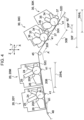
- Fig. 4 illustrates a second modified example of the exemplary embodiment of the present disclosure.
- an acute angle between the X direction and an upstream portion 52C that is a straight portion of the transfer belt 52 positioned on an upstream side of the steering roller 45 and on a downstream side of the loop roller 48 is ⁇ 1.
- An acute angle between the X direction and a downstream portion 52D that is a straight portion positioned on a downstream side of the steering roller 45 and continuous with the upstream portion 52C is ⁇ 2 larger than ⁇ 1.
- Fig. 4 demonstrates that the upstream portion 52C and the downstream portion 52D are not arranged in the Y direction but are arranged in the X direction.
- Two first photoconductor units 20 are provided along the upper surface (outer peripheral surface) of the upstream portion 52C, and two second photoconductor units 30 are provided along the upper surface (outer peripheral surface) of the downstream portion 52D.
- the first photoconductor unit 20 of the second modified example has the same specifications as the first photoconductor unit 20 of the exemplary embodiment.
- the second photoconductor unit 30 of the second modified example has the same specifications as the second photoconductor unit 30 of the exemplary embodiment.
- a distance (adjacency distance) between the rotation axes 20X of the two first photoconductor units 20 is the first distance 20B.
- a distance (adjacency distance) between the rotation axes 30X of the two second photoconductor units 30 is the second distance 30B.
- the horizontal dimension of each first photoconductor unit 20 is 20HL
- the horizontal dimension of each second photoconductor unit 30 is 30HL.
- the horizontal dimension 30HL is smaller than the horizontal dimension 20HL.
- a horizontal dimension 30P is a dimension of the parts of the two second photoconductor units 30 in the X direction.
- a dimension 30F is a dimension of a portion including the two second photoconductor units 30 in the X direction.
- the horizontal dimension 30P is larger than the horizontal dimension 30V in Fig. 1 . Therefore, the horizontal dimension 30F is smaller than the horizontal dimension 30E in Fig. 1 .
- the angle ⁇ 2 is larger than the angle ⁇ 1.
- the two second photoconductor units 30 are provided along the downstream portion 52D.
- the second distance 30B is shorter than the first distance 20B. Therefore, the horizontal dimension of a portion including the downstream portion 52D and the two second photoconductor units 30 is small compared with a case where the downstream portion 52D is parallel to the horizontal direction and the second distance 30B is equal to the first distance 20B.
- the horizontal dimension of the image forming apparatus 10 of the second modified example is reduced compared with the case where the downstream portion 52D is parallel to the horizontal direction and the second distance 30B is equal to the first distance 20B.
- the horizontal dimension 30HL of the second photoconductor unit 30 is smaller than the horizontal dimension 20HL of the first photoconductor unit 20.
- the horizontal dimension of the image forming apparatus 10 of the second modified example is reduced compared with a case where the horizontal dimension 30HL is equal to or larger than the horizontal dimension 20HL.
- the two second photoconductor units 30 When viewed in the Z direction, the two second photoconductor units 30 are partly arranged in the Y direction. Therefore, the horizontal dimension 30F of the portion including the two second photoconductor units 30 is small compared with a case where the two second photoconductor units 30 are arranged away from each other in the X direction when viewed in the Z direction. Thus, the horizontal dimension of the image forming apparatus 10 of the second modified example is reduced compared with a case where the two second photoconductor units 30 are arranged away from each other in the X direction when viewed in the Z direction.
- photoconductor drums image formers
- Any number of photoconductor drums (image formers) may be arranged along the transfer belt 52 as long as the number is three or more.
- Any number of image formers may be provided in the area on the downstream side of the steering roller 45 and on the upstream side of the transfer position for the recording paper P as long as the number is plural.
- the first photoconductor units 20 and the second photoconductor units 30 may form the toner images on the recording paper P (image forming target) transported by a transport belt (not illustrated) provided in place of the transfer belt 52.
- the toner image is described as an example of the image, and is formed by a dry type electrophotographic system.
- the exemplary embodiment of the present disclosure is not limited thereto.
- the toner image may be formed by a wet type electrophotographic system, or the image may be formed by an ink jet system.
- an ink or toner image may be formed on long non-annular continuous paper (image forming target) placed over a plurality of rotators including the driving roller 44, having at least one straight portion by the rotators, and transported by the driving roller 44 and the rotators, and the steering roller (image forming target winding motion correcting roller) 45 may rotatably be in contact with the inner peripheral surface of the continuous paper.
- each of a first distance between the centers of ink jet heads (image formers) corresponding to the first photoconductor units 20 and a second distance between the centers of ink jet heads (image formers) corresponding to the second photoconductor units 30 is set to an integral multiple of each of the outer peripheral length 44C and the outer peripheral length 45C.
- the adjacency distances may be equal to each other within a tolerance. In the case where the image forming apparatus 10 includes the ink jet heads, the adjacency distances may similarly be equal to each other within a tolerance.
- each adjacency distance need not be an integral multiple of each of the outer peripheral length 44C and the outer peripheral length 45C.
- the diameter of the steering roller 45 may differ from the diameter of the driving roller 44. Also in this case, the diameter of the steering roller 45 and the diameter of the driving roller 44 may be set so that each adjacency distance is an integral multiple of each of the outer peripheral length 45C and the outer peripheral length 44C.
- the colors of the images (toner or ink images) to be formed on the image forming target (transfer belt 52 or recording medium P) need not be four colors. For example, six colors may be used for the images.
- all the plurality of first distances may be equal to each other within a tolerance, or at least one first distance may differ from the other first distance.
- description "all the first distances are equal to each other" means that all the plurality of first distances are equal to each other within the tolerance.
- the first distance between the first photoconductor unit 20 at the downstream end and the first photoconductor unit 20 adjacent to this first photoconductor unit 20 may be shorter than the first distance between the first photoconductor unit 20 at the upstream end and the first photoconductor unit 20 adjacent to this first photoconductor unit 20.
- the horizontal dimension of the image forming apparatus 10 may be reduced compared with the case where at least one first distance differs from the other first distance. That is, by setting all the first distances to be equal to the smallest first distance in the case where the first distances differ from each other, the horizontal dimension of the image forming apparatus 10 may be reduced compared with the case where at least one first distance differs from the other first distance.
- all the plurality of second distances may be equal to each other within a tolerance, or at least one second distance may differ from the other second distance.
- description "all the second distances are equal to each other” means that all the plurality of second distances are equal to each other within the tolerance.
- the second distance between the second photoconductor unit 30 at the downstream end and the second photoconductor unit 30 adjacent to this second photoconductor unit 30 may be shorter than the second distance between the second photoconductor unit 30 at the upstream end and the second photoconductor unit 30 adjacent to this second photoconductor unit 30.
- the horizontal dimension of the image forming apparatus 10 may be reduced compared with the case where at least one second distance differs from the other second distance.
Landscapes
- Physics & Mathematics (AREA)
- General Physics & Mathematics (AREA)
- Electrostatic Charge, Transfer And Separation In Electrography (AREA)
- Ink Jet (AREA)
- Electrophotography Configuration And Component (AREA)
- Color Electrophotography (AREA)
Abstract
Description
- The present disclosure relates to an image forming apparatus.
-
Japanese Unexamined Patent Application Publication No. 63-11967 - The image forming apparatus may have an image forming target winding motion correcting roller that corrects a winding motion of the image forming target.
- Accordingly, it is an object of the present disclosure to suppress an increase in a misalignment amount of images formed on the image forming target by a plurality of image formers positioned on a downstream side of the image forming target winding motion correcting roller in a transport direction of the image forming target compared with a case where the distance between the image formers positioned on the downstream side of the image forming target winding motion correcting roller is not an integral multiple of the outer peripheral length of the image forming target winding motion correcting roller.
- According to a first aspect of the present disclosure, there is provided an image forming apparatus comprising an image forming target to be transported along one direction, three or more image formers arranged away from each other along the one direction and configured to form images on the image forming target, and an image forming target winding motion correcting roller rotatably in contact with an inner peripheral surface of the image forming target and positioned on a downstream side of the image former at an upstream end in a transport direction of the image forming target so that a plurality of the image formers are positioned on a downstream side of the image forming target winding motion correcting roller, wherein a distance between the plurality of the image formers positioned on the downstream side of the image forming target winding motion correcting roller is an integral multiple of an outer peripheral length of the image forming target winding motion correcting roller.
- According to a second aspect of the present disclosure, there is provided an image forming apparatus comprising an annular belt configured to circulate in one direction, three or more image formers arranged away from each other along the belt and configured to form images on an image forming target that is the belt or a recording medium transported by the belt, and a belt winding motion correcting roller rotatably in contact with an inner peripheral surface of the belt and positioned on a downstream side of the image former at an upstream end in the one direction so that a plurality of the image formers are positioned on a downstream side of the belt winding motion correcting roller. A distance between the plurality of the image formers positioned on the downstream side of the belt winding motion correcting roller is an integral multiple of an outer peripheral length of the belt winding motion correcting roller.
- According to a third aspect of the present disclosure, the image forming apparatus further comprises a driving roller rotatably in contact with the inner peripheral surface of the belt and configured to circulate the belt. The distance between the image formers is an integral multiple of an outer peripheral length of the driving roller.
- According to a fourth aspect of the present disclosure, the driving roller is positioned on an upstream side of the belt winding motion correcting roller. A first distance between a plurality of the image formers positioned on a downstream side of the driving roller and on an upstream side of the belt winding motion correcting roller is an integral multiple of the outer peripheral length of the driving roller. A second distance between a plurality of the image formers positioned on the downstream side of the belt winding motion correcting roller is shorter than the first distance.
- According to a fifth aspect of the present disclosure, the three or more image formers positioned on the downstream side of the driving roller and on the upstream side of the belt winding motion correcting roller are arranged along one straight portion of the belt. All the first distances are equal to each other.
- According to a sixth aspect of the present disclosure, the three or more image formers positioned on the downstream side of the belt winding motion correcting roller are arranged along another straight portion different from the one straight portion of the belt. All the second distances are equal to each other.
- According to a seventh aspect of the present disclosure, the image forming apparatus further comprises a loop roller rotatably in contact with the inner peripheral surface of the belt, and a push roller positioned between the driving roller and the loop roller, rotatably in contact with an outer peripheral surface of the belt, and configured to push the belt toward an inner periphery.
- According to an eighth aspect of the present disclosure, the image formers are photoconductor drums configured to transfer toner images onto the image forming target. The distance is a distance between rotation axes of the photoconductor drums adjacent to each other.
- According to a ninth aspect of the present disclosure, there is provided an image forming apparatus comprising an image forming target to be transported along one direction, a plurality of image formers arranged away from each other along the one direction and configured to form images on the image forming target, and an image forming target winding motion correcting roller rotatably in contact with an inner peripheral surface of the image forming target and positioned on an upstream side of the plurality of image formers in a transport direction of the image forming target. A distance between the plurality of image formers is an integral multiple of an outer peripheral length of the image forming target winding motion correcting roller.
- According to a tenth aspect of the present disclosure, there is provided an image forming apparatus comprising an annular belt configured to circulate in one direction, a plurality of image formers arranged away from each other along the belt and configured to form images on an image forming target that is the belt or a recording medium transported by the belt, and a belt winding motion correcting roller rotatably in contact with an inner peripheral surface of the belt and positioned on an upstream side of the plurality of image formers in the one direction. A distance between the plurality of image formers is an integral multiple of an outer peripheral length of the belt winding motion correcting roller.
- According to the first aspect of the present disclosure, the increase in the misalignment amount of the images formed on the image forming target by the plurality of image formers positioned on the downstream side of the image forming target winding motion correcting roller in the transport direction of the image forming target is suppressed compared with the case where the distance between the image formers positioned on the downstream side of the image forming target winding motion correcting roller is not the integral multiple of the outer peripheral length of the image forming target winding motion correcting roller.
- According to the second aspect of the present disclosure, the increase in the misalignment amount of the images formed on the image forming target by the plurality of image formers positioned on the downstream side of the belt winding motion correcting roller in the circulating direction of the belt is suppressed compared with a case where the distance between the image formers positioned on the downstream side of the belt winding motion correcting roller differs from the integral multiple of the outer peripheral length of the belt winding motion correcting roller.
- According to the third aspect of the present disclosure, the increase in the misalignment amount of the images formed on the image forming target by the image formers positioned on the downstream side of the belt winding motion correcting roller is suppressed compared with a case where the distance between the image formers differs from the integral multiple of the outer peripheral length of the driving roller.
- According to the fourth aspect of the present disclosure, the increase in the misalignment amount of the images formed on the image forming target by the plurality of image formers positioned on the downstream side of the belt winding motion correcting roller is suppressed compared with a case where the second distance is equal to the first distance.
- According to the fifth aspect of the present disclosure, the horizontal dimension of the image forming apparatus may be reduced compared with a case where at least one first distance differs from the other first distance.
- According to the sixth aspect of the present disclosure, the horizontal dimension of the image forming apparatus may be reduced compared with a case where at least one second distance differs from the other second distance.
- According to the seventh aspect of the present disclosure, the overlap angle between the driving roller and the belt increases compared with a case where the belt is shaped straight between the driving roller and the loop roller.
- According to the eighth aspect of the present disclosure, the increase in the misalignment amount of the images formed on the image forming target by the plurality of image formers positioned on the downstream side of the belt winding motion correcting roller is suppressed compared with a case where the distance between the image formers positioned on the downstream side of the belt winding motion correcting roller differs from the integral multiple of the outer peripheral length of the belt winding motion correcting roller in the structure in which the image formers form toner images on the image forming target.
- According to the ninth aspect of the present disclosure, the increase in the misalignment amount of the images formed on the image forming target by the plurality of image formers positioned on the downstream side of the image forming target winding motion correcting roller in the transport direction of the image forming target is suppressed compared with the case where the distance between the image formers positioned on the downstream side of the image forming target winding motion correcting roller is not the integral multiple of the outer peripheral length of the image forming target winding motion correcting roller.
- According to the tenth aspect of the present disclosure, the increase in the misalignment amount of the images formed on the image forming target by the plurality of image formers positioned on the downstream side of the belt winding motion correcting roller in the circulating direction of the belt is suppressed compared with the case where the distance between the image formers positioned on the downstream side of the belt winding motion correcting roller differs from the integral multiple of the outer peripheral length of the belt winding motion correcting roller.
- An exemplary embodiment of the present disclosure will be described in detail based on the following figures, wherein:
-
Fig. 1 is a schematic structural view illustrating an image forming apparatus according to an exemplary embodiment; -
Fig. 2 is a side view illustrating a transfer belt, a driving roller, a loop roller, and a push roller according to the exemplary embodiment; -
Fig. 3 is a schematic structural view illustrating a part of an image forming apparatus according to a first modified example of the exemplary embodiment; and -
Fig. 4 is a schematic structural view illustrating a part of an image forming apparatus according to a second modified example of the exemplary embodiment. - An exemplary embodiment of the present disclosure is described in detail below with reference to the drawings. An upstream side in a transport direction of recording paper P that is an example of a recording medium may hereinafter be referred to simply as "upstream side". A downstream side in the transport direction may hereinafter be referred to simply as "downstream side". An upstream side in a circulating direction (transport direction) of a transfer belt (belt) (image forming target) 52 may hereinafter be referred to simply as "upstream side". A downstream side in the circulating direction (transport direction) may hereinafter be referred to simply as "downstream side".
- As illustrated in
Fig. 1 , animage forming apparatus 10 uses, for example, an electrophotographic system that forms a toner image (example of an image) on the recording paper P. Theimage forming apparatus 10 includes animage forming unit 12, a container 14, atransporter 16, and afixing device 18 in an apparatus body (not illustrated). The components of the image forming apparatus 10 (image forming unit 12, container 14,transporter 16, and fixing device 18) are described below. - In the following description, a width direction (horizontal direction) of the apparatus body is an X direction, an up-and-down direction (vertical direction) of the apparatus body is a Y direction, and a direction orthogonal to the X direction and the Y direction (direction orthogonal to each drawing sheet) is a Z direction.
- The
image forming unit 12 has a function of forming toner images on the recording paper P. Specifically, theimage forming unit 12 includes first photoconductor units 20, second photoconductor units 30, and atransfer device 50. - As illustrated in
Fig. 1 , two first photoconductor units 20 and two second photoconductor units 30 are provided. The first photoconductor units 20 and the second photoconductor units 30 are detachable from the apparatus body. Theimage forming apparatus 10 of this exemplary embodiment includes first photoconductor units 20Y and 20M for two colors that are yellow (Y) and magenta (M), and second photoconductor units 30C and 30K for two colors that are cyan (C) and black (K). - To distinguish yellow (Y), magenta (M), cyan (C), and black (K), the reference numerals of the members may be suffixed with letters "Y", "M", "C", and "K". Without the color distinction, the letters "Y", "M", "C", and "K" may be omitted.
- In the
transfer device 50 described later, thetransfer belt 52 made of an elastic material has two straight portions shaped straight when viewed in the Z direction. The two straight portions are anupper portion 52A and alower portion 52B. When viewed in the Z direction, theupper portion 52A extends along the X direction, and thelower portion 52B is inclined with respect to the X direction. That is, when viewed in the Z direction, an angle θB (seeFig. 1 ) between thelower portion 52B and the X direction is an acute angle and is larger than an angle θA (not illustrated) between theupper portion 52A and the X direction. The angle θA is 0° or an acute angle slightly larger than 0°. When viewed in the Z direction, theupper portion 52A and thelower portion 52B are arranged in the Y direction. The term "straight portion" in this specification and in the claims is not limited to a portion shaped completely straight. For example, theupper portion 52A positioned between a steeringroller 45 and aloop roller 48 described later is slightly concave at a part pushed by two first photoconductor drums 22 and twofirst transfer rollers 41, but corresponds to the "straight portion". Similarly, thelower portion 52B positioned between the steeringroller 45 and aloop roller 47 is slightly concave at a part pushed by two second photoconductor drums 32 and twofirst transfer rollers 41, but corresponds to the "straight portion". - The two first photoconductor units 20 face the outer peripheral surface (upper surface) of the
upper portion 52A, and are arranged in the X direction along theupper portion 52A. In particular, the two first photoconductor units 20 are arranged so that the flat lower surfaces ofsupport plates 28 of the first photoconductor units 20 described later are parallel to the outer peripheral surface (upper surface) of theupper portion 52A. Thus, the length of the apparatus body in the Y direction is reduced compared with a case where the lower surfaces are not parallel to the outer peripheral surface. The lower surface of thesupport plate 28 and the outer peripheral surface of theupper portion 52A face each other in the Y direction at a short distance therebetween. Thus, the length of the apparatus body in the Y direction is reduced. Each first photoconductor unit 20 includes thefirst photoconductor drum 22 that rotates in one direction (e.g., a counterclockwise direction inFig. 1 ). Eachfirst photoconductor drum 22 is rotatable about arotation axis 20X extending in the Z direction. When viewed in the Z direction, a distance (adjacency distance) between the rotation axes 20X of the two first photoconductor units 20 is afirst distance 20B. Each first photoconductor unit 20 includes afirst charger 24, afirst exposer 25, afirst developer 26, and afirst remover 27 in order from an upstream side in the rotating direction of thefirst photoconductor drum 22. Each first photoconductor unit 20 includes a pair ofsupport plates 28 spaced away from each other in the Z direction. InFig. 1 , illustration of onesupport plate 28 is omitted. Thefirst charger 24, thefirst exposer 25, thefirst developer 26, and thefirst remover 27 extend in the Z direction. Both ends of each of thefirst charger 24, thefirst exposer 25, thefirst developer 26, and thefirst remover 27 in the Z direction are supported by the pair ofsupport plates 28. Relative movement of the pair ofsupport plates 28 is restricted. As illustrated inFig. 1 , the dimension of each first photoconductor unit 20 in the X direction is ahorizontal dimension 20L. - The two second photoconductor units 30 face the outer peripheral surface (lower surface) of the
lower portion 52B, and are arranged along thelower portion 52B. Each second photoconductor unit 30 includes thesecond photoconductor drum 32 that rotates in one direction (e.g., a counterclockwise direction inFig. 1 ). Eachsecond photoconductor drum 32 is rotatable about arotation axis 30X extending in the Z direction. When viewed in the Z direction, a distance (adjacency distance) between the rotation axes 30X of the two second photoconductor units 30 is asecond distance 30B. Each second photoconductor unit 30 includes asecond charger 34, asecond exposer 35, asecond developer 36, and asecond remover 37 in order from an upstream side in the rotating direction of thesecond photoconductor drum 32. Each second photoconductor unit 30 includes a pair ofsecond support plates 38 spaced away from each other in the Z direction. InFig. 1 , illustration of onesecond support plate 38 is omitted. Thesecond charger 34, thesecond exposer 35, thesecond developer 36, and thesecond remover 37 extend in the Z direction. Both ends of each of thesecond charger 34, thesecond exposer 35, thesecond developer 36, and thesecond remover 37 in the Z direction are supported by the pair ofsecond support plates 38. Relative movement of the pair ofsecond support plates 38 is restricted. As illustrated inFig. 1 , the dimension of each second photoconductor unit 30 in the X direction is ahorizontal dimension 30L. - The term "image former" in this specification and in the claims causes a toner or ink to adhere to the image forming target (e.g., the transfer belt 52). That is, the
first photoconductor drum 22 of the first photoconductor unit 20 corresponds to the "image former", and thesecond photoconductor drum 32 of the second photoconductor unit 30 corresponds to the "image former". That is, thefirst charger 24, thefirst exposer 25, thefirst developer 26, and thefirst remover 27 do not correspond to the "image former". Similarly, thesecond charger 34, thesecond exposer 35, thesecond developer 36, and thesecond remover 37 do not correspond to the "image former". When theimage forming apparatus 10 uses an ink jet system as described later, an ink jet head corresponds to the "image former". - As illustrated in
Fig. 1 , thefirst developer 26 includes a developingroller 26A, acollection auger 26B, asupply auger 26C, and a stirringauger 26D. Similarly, thesecond developer 36 includes a developingroller 36A, acollection auger 36B, asupply auger 36C, and a stirringauger 36D. Thesupply auger 26C and the stirringauger 26D are arranged in the X direction. Thesupply auger 36C and the stirringauger 36D are arranged in the Y direction. Therefore, the horizontal dimension of thesecond developer 36 is smaller than the horizontal dimension of thefirst developer 26. Thus, thehorizontal dimension 30L is smaller than thehorizontal dimension 20L. - As illustrated in
Fig. 1 , the two first photoconductor units 20 are arranged in the X direction when viewed in the Z direction. That is, the two first photoconductor units 20 are not arranged in the Y direction. When viewed in the Z direction, the two second photoconductor units 30 are partly arranged in the Y direction. InFig. 1 , ahorizontal dimension 30V is a dimension of the parts of the two second photoconductor units 30 in the X direction. InFig. 1 , ahorizontal dimension 30E is a horizontal dimension of a portion including the two second photoconductor units 30. InFig. 1 , ahorizontal dimension 30G is a horizontal dimension of a portion including thelower portion 52B and the two second photoconductor units 30. - In each first photoconductor unit 20, the
first charger 24 charges the outer peripheral surface of thefirst photoconductor drum 22. Thefirst exposer 25 exposes the charged outer peripheral surface of thefirst photoconductor drum 22 to light to form an electrostatic latent image on the outer peripheral surface of thefirst photoconductor drum 22. Thefirst developer 26 develops the formed electrostatic latent image to form a toner image. After the toner image is transferred onto thetransfer belt 52, thefirst remover 27 removes the residual toner on the outer peripheral surface of thefirst photoconductor drum 22. - In each second photoconductor unit 30, the
second charger 34 charges the outer peripheral surface of thesecond photoconductor drum 32. Thesecond exposer 35 exposes the charged outer peripheral surface of thesecond photoconductor drum 32 to light to form an electrostatic latent image on the outer peripheral surface of thesecond photoconductor drum 32. Thesecond developer 36 develops the formed electrostatic latent image to form a toner image. After the toner image is transferred onto thetransfer belt 52, thesecond remover 37 removes the residual toner on the outer peripheral surface of thesecond photoconductor drum 32. - As illustrated in
Fig. 1 , thetransfer device 50 includes fourfirst transfer rollers 41 that are examples of a first transferer, thetransfer belt 52 that is an example of an intermediate transferer, and atransfer barrel 60 that is an example of a second transferer. In thetransfer device 50, the toner images formed on the outer peripheral surfaces of the first photoconductor drums 22 are firstly transferred onto thetransfer belt 52 while being laid over one another, and the laid toner images are secondly transferred onto the recording paper P. - As illustrated in
Fig. 1 , eachfirst transfer roller 41 facing theupper portion 52A transfers the toner image formed on the outer peripheral surface of eachfirst photoconductor drum 22 onto the outer peripheral surface of thetransfer belt 52 at a first transfer position T1 between thefirst photoconductor drum 22 and thefirst transfer roller 41. Eachfirst transfer roller 41 facing thelower portion 52B transfers the toner image formed on the outer peripheral surface of eachsecond photoconductor drum 32 onto the outer peripheral surface of thetransfer belt 52 at a first transfer position T1 between thesecond photoconductor drum 32 and thefirst transfer roller 41. A distance between the first transfer positions T1 of the two first photoconductor drums 22 corresponds to thefirst distance 20B. Similarly, a distance between the first transfer positions T1 of the two second photoconductor drums 32 corresponds to thesecond distance 30B. In this exemplary embodiment, the toner image formed on the outer peripheral surface of thefirst photoconductor drum 22 is transferred onto the outer peripheral surface of thetransfer belt 52 at the first transfer position T1 by applying a first transfer voltage between thefirst transfer roller 41 and thefirst photoconductor drum 22. Similarly, the toner image formed on the outer peripheral surface of thesecond photoconductor drum 32 is transferred onto the outer peripheral surface of thetransfer belt 52 at the first transfer position T1 by applying the first transfer voltage between thefirst transfer roller 41 and thesecond photoconductor drum 32. - As illustrated in
Fig. 1 , thetransfer belt 52 has an annular shape so that the toner images are transferred onto the outer peripheral surface, and is looped around a drivingroller 44, the steeringroller 45, abackup roller 46, theloop roller 47, theloop roller 48, and apush roller 49 to determine the posture. The steeringroller 45 is an example of a belt winding motion correcting roller (image forming target winding motion correcting roller). - The driving
roller 44 having a circular cross section is driven by a driver (not illustrated) to rotate about anaxis 44X extending in the Z direction, thereby circulating thetransfer belt 52 in a circulating direction indicated by an arrow A at a predetermined speed. - The diameter of the steering
roller 45 having a circular cross section is equal to the diameter of the drivingroller 44 within a tolerance. In other words, an outer peripheral length 45C of the steeringroller 45 is equal to an outer peripheral length 44C of the drivingroller 44 within a tolerance. The steeringroller 45 is rotatable about anaxis 45X extending in the Z direction. The steeringroller 45 is configured to swivel about a center in the direction of theaxis 45X. Therefore, the steeringroller 45 suppresses a winding motion of thetransfer belt 52. - Each of the
first distance 20B between the two first photoconductor drums 22 and thesecond distance 30B between the two second photoconductor drums 32 is set to an integral multiple of each of the outer peripheral length 44C of the drivingroller 44 and the outer peripheral length 45C of the steeringroller 45. Thesecond distance 30B is shorter than thefirst distance 20B. For example, in this exemplary embodiment, thefirst distance 20B is set to four times as large as each of the outer peripheral length 44C and the outer peripheral length 45C, and thesecond distance 30B is set to three times as large as each of the outer peripheral length 44C and the outer peripheral length 45C. - A distance along the
transfer belt 52 between the first transfer position T1 of thefirst photoconductor drum 22 on the downstream side and the first transfer position T1 of thesecond photoconductor drum 32 on the upstream side differs from thefirst distance 20B and thesecond distance 30B. That is, the distance along thetransfer belt 52 between the first transfer position T1 of thefirst photoconductor drum 22 on the downstream side and the first transfer position T1 of thesecond photoconductor drum 32 on the upstream side does not correspond to the "adjacency distance (first distance, second distance)" in the claims. The distance along thetransfer belt 52 between the first transfer position T1 of thefirst photoconductor drum 22 on the downstream side and the first transfer position T1 of thesecond photoconductor drum 32 on the upstream side is also set to an integral multiple of each of the outer peripheral length 44C of the drivingroller 44 and the outer peripheral length 45C of the steeringroller 45. - The
backup roller 46 faces thetransfer barrel 60 across thetransfer belt 52. A contact area between thetransfer barrel 60 and thetransfer belt 52 is a nip area Np (seeFig. 1 ). The nip area Np is a second transfer position T2 where the toner images are transferred from thetransfer belt 52 onto the recording paper P. - The
loop roller 47 positioned on a downstream side of the second photoconductor unit 30K and on an upstream side of thebackup roller 46 is rotatably in contact with the inner peripheral surface of thetransfer belt 52. Theloop roller 48 positioned on an upstream side of the first photoconductor unit 20Y and on a downstream side of the drivingroller 44 is rotatably in contact with the inner peripheral surface of thetransfer belt 52. Thepush roller 49 positioned on an upstream side of theloop roller 48 and on a downstream side of the drivingroller 44 is rotatably in contact with the outer peripheral surface of thetransfer belt 52 and pushes thetransfer belt 52 toward the inner periphery. If thepush roller 49 is not provided, a portion of thetransfer belt 52 between the drivingroller 44 and theloop roller 48 is shaped as indicated by an imaginary line inFig. 2 . In this case, an overlap angle between thetransfer belt 52 and the drivingroller 44 is θI. In this exemplary embodiment, the overlap angle between thetransfer belt 52 and the drivingroller 44 is θ because thepush roller 49 is provided.Fig. 2 demonstrates that the overlap angle θ is larger than the overlap angle θI. - As illustrated in
Fig. 1 , thetransporter 16 includes a transport device (not illustrated) that transports the recording paper P fed out from the container 14 in an arrow B direction. The transport device transports the recording paper P from the container 14 to thetransfer barrel 60. After the toner images are secondly transferred onto the recording paper P passing over the transfer barrel 60 (second transfer position T2), the transport device transports the recording paper P to the fixingdevice 18. - As illustrated in
Fig. 1 , the fixingdevice 18 includes aheating roller 42 that is an example of a heating member, and a pressurizingroller 43 that is an example of a pressurizing member. In the fixingdevice 18, the toner images transferred onto the recording paper P at thetransfer barrel 60 are fixed onto the recording paper P by heating and pressurizing the recording paper P between theheating roller 42 and the pressurizingroller 43. - Next, the
image forming apparatus 10 having the structure described above is described in detail. - In the
image forming apparatus 10 of this exemplary embodiment, the second distance (adjacency distance) 30B between the rotation axes 30X of the two second photoconductor drums 32 (image formers) positioned on the downstream side of the steeringroller 45 and on the upstream side of the transfer position for the recording paper P is an integral multiple of the outer peripheral length 45C of the steeringroller 45. Thus, the increase in the misregistration amount of the toner images formed on the transfer belt (image forming target) 52 by the two second photoconductor drums 32 positioned on the downstream side of the steeringroller 45 is suppressed compared with a case where thesecond distance 30B differs from the integral multiple of the outer peripheral length 45C. - In the
image forming apparatus 10, each of thefirst distance 20B between the two first photoconductor drums 22 and thesecond distance 30B between the two second photoconductor drums 32 is set to an integral multiple of the outer peripheral length 44C of the drivingroller 44. Thus, the increase in the misregistration amount of the toner images formed on the transfer belt (image forming target) 52 by the two second photoconductor drums 32 positioned on the downstream side of the steeringroller 45 is suppressed compared with a case where each of thefirst distance 20B and thesecond distance 30B is set to a value different from the integral multiple of the outer peripheral length 44C. - The
second distance 30B between the two second photoconductor drums 32 positioned on the downstream side of the first photoconductor drums 22 is shorter than thefirst distance 20B. In a comparative example (not illustrated) in which thefirst distance 20B is equal to thesecond distance 30B, thesecond distance 30B is adjusted to thefirst distance 20B. Therefore, a distance along thetransfer belt 52 from the drivingroller 44 to the second photoconductor unit 30K is shorter in this exemplary embodiment than in the comparative example. As this distance increases, the cumulative amounts of variation in the speed of thetransfer belt 52 and variation in the adjacency distance increase. In the comparative example, the misregistration amount of the toner images on the second photoconductor unit 30C and the second photoconductor unit 30K tends to increase compared with the misregistration amount of the toner images on the first photoconductor unit 20Y and the first photoconductor unit 20M. In the exemplary embodiment, the distance between the second photoconductor unit 30C and the second photoconductor unit 30K (second distance 30B) is shorter than in the comparative example. Therefore, the cumulative amounts of the variation in the speed and the variation in the adjacency distance are smaller than in the comparative example. Thus, in this exemplary embodiment, the increase in the misregistration amount of the toner images for the photoconductor drum positioned on the downstream side on thetransfer belt 52 is suppressed compared with a case where thefirst distance 20B is equal to thesecond distance 30B. - The
push roller 49 that is positioned between the drivingroller 44 and theloop roller 48 and is rotatably in contact with the outer peripheral surface of thetransfer belt 52 pushes thetransfer belt 52 toward the inner periphery. Thus, the overlap angle (θ) between the drivingroller 44 and thetransfer belt 52 increases compared with a case where thetransfer belt 52 is shaped straight between the drivingroller 44 and theloop roller 48. - For example, a
transfer belt 52 of animage forming apparatus 10 according to a first modified example illustrated inFig. 3 includes onestraight portion 52E. InFig. 3 , illustration of the developingroller 26A, thecollection auger 26B, thesupply auger 26C, the stirringauger 26D, the developingroller 36A, thecollection auger 36B, thesupply auger 36C, and the stirringauger 26D is omitted. The end of thestraight portion 52E on the upstream side is looped around the steeringroller 45, and the end of thestraight portion 52E on the downstream side is looped around the drivingroller 44. That is, the steeringroller 45 is positioned on the upstream side of the drivingroller 44. Thisimage forming apparatus 10 includes two first photoconductor units 20 and two second photoconductor units 30 arranged along thestraight portion 52E. That is, all the photoconductor units (first photoconductor units 20 and second photoconductor units 30) of theimage forming apparatus 10 are positioned on the downstream side of the steeringroller 45 and on the upstream side of the drivingroller 44. - An
adjacency distance 23B between therotation axis 20X of thefirst photoconductor drum 22 on the downstream side and therotation axis 30X of thesecond photoconductor drum 32 on the upstream side is set to an integral multiple of each of the outer peripheral length 44C of the drivingroller 44 and the outer peripheral length 45C of the steeringroller 45. There is a relationship offirst distance 20B >adjacency distance 23B >second distance 30B. For example, thefirst distance 20B is set to four times as large as each of the outer peripheral length 44C and the outer peripheral length 45C, theadjacency distance 23B is set to 3.5 times as large as each of the outer peripheral length 44C and the outer peripheral length 45C, and thesecond distance 30B is set to three times as large as each of the outer peripheral length 44C and the outer peripheral length 45C. - In the
image forming apparatus 10 according to the first modified example, each of thefirst distance 20B, theadjacency distance 23B, and thesecond distance 30B is set to the integral multiple of each of the outer peripheral length 45C of the steeringroller 45 and the outer peripheral length 44C of the drivingroller 44. Thus, the misregistration between the toner images formed in different colors on thetransfer belt 52 by the first photoconductor units 20 and the second photoconductor units 30 is unlikely to occur compared with a case where each of thefirst distance 20B, theadjacency distance 23B, and thesecond distance 30B is set to a value different from the integral multiple of each of the outer peripheral length 45C and the outer peripheral length 44C. - The
adjacency distance 23B is smaller than thefirst distance 20B, and thesecond distance 30B is smaller than theadjacency distance 23B. Thus, the increase in the misregistration amount of the toner images for the photoconductor drum positioned on the downstream side on thetransfer belt 52 is suppressed compared with a case where thefirst distance 20B, theadjacency distance 23B, and thesecond distance 30B are equal to each other. -
Fig. 4 illustrates a second modified example of the exemplary embodiment of the present disclosure. In animage forming apparatus 10 of the second modified example, an acute angle between the X direction and anupstream portion 52C that is a straight portion of thetransfer belt 52 positioned on an upstream side of the steeringroller 45 and on a downstream side of theloop roller 48 is θ1. An acute angle between the X direction and adownstream portion 52D that is a straight portion positioned on a downstream side of the steeringroller 45 and continuous with theupstream portion 52C is θ2 larger than θ1.Fig. 4 demonstrates that theupstream portion 52C and thedownstream portion 52D are not arranged in the Y direction but are arranged in the X direction. Two first photoconductor units 20 are provided along the upper surface (outer peripheral surface) of theupstream portion 52C, and two second photoconductor units 30 are provided along the upper surface (outer peripheral surface) of thedownstream portion 52D. The first photoconductor unit 20 of the second modified example has the same specifications as the first photoconductor unit 20 of the exemplary embodiment. The second photoconductor unit 30 of the second modified example has the same specifications as the second photoconductor unit 30 of the exemplary embodiment. - When viewed in the Z direction, a distance (adjacency distance) between the rotation axes 20X of the two first photoconductor units 20 is the
first distance 20B. When viewed in the Z direction, a distance (adjacency distance) between the rotation axes 30X of the two second photoconductor units 30 is thesecond distance 30B. As illustrated inFig. 4 , the horizontal dimension of each first photoconductor unit 20 is 20HL, and the horizontal dimension of each second photoconductor unit 30 is 30HL. The horizontal dimension 30HL is smaller than the horizontal dimension 20HL. - When viewed in the Z direction, the two second photoconductor units 30 are partly arranged in the Y direction. In
Fig. 4 , ahorizontal dimension 30P is a dimension of the parts of the two second photoconductor units 30 in the X direction. InFig. 4 , adimension 30F is a dimension of a portion including the two second photoconductor units 30 in the X direction. Thehorizontal dimension 30P is larger than thehorizontal dimension 30V inFig. 1 . Therefore, thehorizontal dimension 30F is smaller than thehorizontal dimension 30E inFig. 1 . - In the
image forming apparatus 10 of the second modified example illustrated inFig. 4 , the angle θ2 is larger than the angle θ1. The two second photoconductor units 30 are provided along thedownstream portion 52D. Thesecond distance 30B is shorter than thefirst distance 20B. Therefore, the horizontal dimension of a portion including thedownstream portion 52D and the two second photoconductor units 30 is small compared with a case where thedownstream portion 52D is parallel to the horizontal direction and thesecond distance 30B is equal to thefirst distance 20B. Thus, when viewed in the Z direction, the horizontal dimension of theimage forming apparatus 10 of the second modified example is reduced compared with the case where thedownstream portion 52D is parallel to the horizontal direction and thesecond distance 30B is equal to thefirst distance 20B. - The horizontal dimension 30HL of the second photoconductor unit 30 is smaller than the horizontal dimension 20HL of the first photoconductor unit 20. Thus, when viewed in the Z direction, the horizontal dimension of the
image forming apparatus 10 of the second modified example is reduced compared with a case where the horizontal dimension 30HL is equal to or larger than the horizontal dimension 20HL. - When viewed in the Z direction, the two second photoconductor units 30 are partly arranged in the Y direction. Therefore, the
horizontal dimension 30F of the portion including the two second photoconductor units 30 is small compared with a case where the two second photoconductor units 30 are arranged away from each other in the X direction when viewed in the Z direction. Thus, the horizontal dimension of theimage forming apparatus 10 of the second modified example is reduced compared with a case where the two second photoconductor units 30 are arranged away from each other in the X direction when viewed in the Z direction. - Any number of photoconductor drums (image formers) may be arranged along the
transfer belt 52 as long as the number is three or more. - Any number of image formers may be provided in the area on the downstream side of the steering
roller 45 and on the upstream side of the transfer position for the recording paper P as long as the number is plural. - In the
image forming apparatus 10, the first photoconductor units 20 and the second photoconductor units 30 may form the toner images on the recording paper P (image forming target) transported by a transport belt (not illustrated) provided in place of thetransfer belt 52. - The toner image is described as an example of the image, and is formed by a dry type electrophotographic system. The exemplary embodiment of the present disclosure is not limited thereto. For example, the toner image may be formed by a wet type electrophotographic system, or the image may be formed by an ink jet system.
- In the
image forming apparatus 10, an ink or toner image may be formed on long non-annular continuous paper (image forming target) placed over a plurality of rotators including the drivingroller 44, having at least one straight portion by the rotators, and transported by the drivingroller 44 and the rotators, and the steering roller (image forming target winding motion correcting roller) 45 may rotatably be in contact with the inner peripheral surface of the continuous paper. - In a case where the
image forming apparatus 10 uses the ink jet system, each of a first distance between the centers of ink jet heads (image formers) corresponding to the first photoconductor units 20 and a second distance between the centers of ink jet heads (image formers) corresponding to the second photoconductor units 30 is set to an integral multiple of each of the outer peripheral length 44C and the outer peripheral length 45C. - In the case where the
image forming apparatus 10 includes the first photoconductor units 20 and the second photoconductor units 30, the adjacency distances may be equal to each other within a tolerance. In the case where theimage forming apparatus 10 includes the ink jet heads, the adjacency distances may similarly be equal to each other within a tolerance. - Both in the cases where the
image forming apparatus 10 includes the first photoconductor units 20 and the second photoconductor units 30 and where theimage forming apparatus 10 includes the ink jet heads, each adjacency distance need not be an integral multiple of each of the outer peripheral length 44C and the outer peripheral length 45C. - The diameter of the steering
roller 45 may differ from the diameter of the drivingroller 44. Also in this case, the diameter of the steeringroller 45 and the diameter of the drivingroller 44 may be set so that each adjacency distance is an integral multiple of each of the outer peripheral length 45C and the outer peripheral length 44C. - The colors of the images (toner or ink images) to be formed on the image forming target (transfer
belt 52 or recording medium P) need not be four colors. For example, six colors may be used for the images. - For example, in a case where three or more first photoconductor units 20 are arranged along the
upper portion 52A or theupstream portion 52C, all the plurality of first distances may be equal to each other within a tolerance, or at least one first distance may differ from the other first distance. In the claims, description "all the first distances are equal to each other" means that all the plurality of first distances are equal to each other within the tolerance. For example, the first distance between the first photoconductor unit 20 at the downstream end and the first photoconductor unit 20 adjacent to this first photoconductor unit 20 may be shorter than the first distance between the first photoconductor unit 20 at the upstream end and the first photoconductor unit 20 adjacent to this first photoconductor unit 20. In the case where all the plurality of first distances are equal to each other within the tolerance, the horizontal dimension of theimage forming apparatus 10 may be reduced compared with the case where at least one first distance differs from the other first distance. That is, by setting all the first distances to be equal to the smallest first distance in the case where the first distances differ from each other, the horizontal dimension of theimage forming apparatus 10 may be reduced compared with the case where at least one first distance differs from the other first distance. - For example, in a case where three or more second photoconductor units 30 are arranged along the
lower portion 52B or thedownstream portion 52D, all the plurality of second distances may be equal to each other within a tolerance, or at least one second distance may differ from the other second distance. In the claims, description "all the second distances are equal to each other" means that all the plurality of second distances are equal to each other within the tolerance. For example, the second distance between the second photoconductor unit 30 at the downstream end and the second photoconductor unit 30 adjacent to this second photoconductor unit 30 may be shorter than the second distance between the second photoconductor unit 30 at the upstream end and the second photoconductor unit 30 adjacent to this second photoconductor unit 30. In the case where all the plurality of second distances are equal to each other within the tolerance, the horizontal dimension of theimage forming apparatus 10 may be reduced compared with the case where at least one second distance differs from the other second distance. - The foregoing description of the exemplary embodiments of the present disclosure has been provided for the purposes of illustration and description. It is not intended to be exhaustive or to limit the disclosure to the precise forms disclosed. Obviously, many modifications and variations will be apparent to practitioners skilled in the art. The embodiments were chosen and described in order to best explain the principles of the disclosure and its practical applications, thereby enabling others skilled in the art to understand the disclosure for various embodiments and with the various modifications as are suited to the particular use contemplated. It is intended that the scope of the disclosure be defined by the following claims and their equivalents.
Claims (10)
- An image forming apparatus comprising:an image forming target to be transported along one direction;three or more image formers arranged away from each other along the one direction and configured to form images on the image forming target; andan image forming target winding motion correcting roller rotatably in contact with an inner peripheral surface of the image forming target and positioned on a downstream side of the image former at an upstream end in a transport direction of the image forming target so that a plurality of the image formers are positioned on a downstream side of the image forming target winding motion correcting roller,wherein a distance between the plurality of the image formers positioned on the downstream side of the image forming target winding motion correcting roller is an integral multiple of an outer peripheral length of the image forming target winding motion correcting roller.
- An image forming apparatus comprising:an annular belt configured to circulate in one direction;three or more image formers arranged away from each other along the belt and configured to form images on an image forming target that is the belt or a recording medium transported by the belt; anda belt winding motion correcting roller rotatably in contact with an inner peripheral surface of the belt and positioned on a downstream side of the image former at an upstream end in the one direction so that a plurality of the image formers are positioned on a downstream side of the belt winding motion correcting roller,wherein a distance between the plurality of the image formers positioned on the downstream side of the belt winding motion correcting roller is an integral multiple of an outer peripheral length of the belt winding motion correcting roller.
- The image forming apparatus according to Claim 2, further comprising a driving roller rotatably in contact with the inner peripheral surface of the belt and configured to circulate the belt,
wherein the distance between the image formers is an integral multiple of an outer peripheral length of the driving roller. - The image forming apparatus according to Claim 3,wherein the driving roller is positioned on an upstream side of the belt winding motion correcting roller,wherein a first distance between a plurality of the image formers positioned on a downstream side of the driving roller and on an upstream side of the belt winding motion correcting roller is an integral multiple of the outer peripheral length of the driving roller, andwherein a second distance between a plurality of the image formers positioned on the downstream side of the belt winding motion correcting roller is shorter than the first distance.
- The image forming apparatus according to Claim 4,wherein the three or more image formers positioned on the downstream side of the driving roller and on the upstream side of the belt winding motion correcting roller are arranged along one straight portion of the belt, andwherein all the first distances are equal to each other.
- The image forming apparatus according to Claim 5,wherein the three or more image formers positioned on the downstream side of the belt winding motion correcting roller are arranged along another straight portion different from the one straight portion of the belt, andwherein all the second distances are equal to each other.
- The image forming apparatus according to any one of Claims 3 to 6, further comprising:a loop roller rotatably in contact with the inner peripheral surface of the belt; anda push roller positioned between the driving roller and the loop roller, rotatably in contact with an outer peripheral surface of the belt, and configured to push the belt toward an inner periphery.
- The image forming apparatus according to any one of Claims 1 to 7,wherein the image formers are photoconductor drums configured to transfer toner images onto the image forming target, andwherein the distance is a distance between rotation axes of the photoconductor drums adjacent to each other.
- An image forming apparatus comprising:an image forming target to be transported along one direction;a plurality of image formers arranged away from each other along the one direction and configured to form images on the image forming target; andan image forming target winding motion correcting roller rotatably in contact with an inner peripheral surface of the image forming target and positioned on an upstream side of the plurality of image formers in a transport direction of the image forming target,wherein a distance between the plurality of image formers is an integral multiple of an outer peripheral length of the image forming target winding motion correcting roller.
- An image forming apparatus comprising:an annular belt configured to circulate in one direction;a plurality of image formers arranged away from each other along the belt and configured to form images on an image forming target that is the belt or a recording medium transported by the belt; anda belt winding motion correcting roller rotatably in contact with an inner peripheral surface of the belt and positioned on an upstream side of the plurality of image formers in the one direction,wherein a distance between the plurality of image formers is an integral multiple of an outer peripheral length of the belt winding motion correcting roller.
Applications Claiming Priority (1)
| Application Number | Priority Date | Filing Date | Title |
|---|---|---|---|
| JP2021137625A JP7700581B2 (en) | 2021-08-25 | 2021-08-25 | Image forming device |
Publications (2)
| Publication Number | Publication Date |
|---|---|
| EP4141564A1 true EP4141564A1 (en) | 2023-03-01 |
| EP4141564B1 EP4141564B1 (en) | 2025-10-08 |
Family
ID=81326991
Family Applications (1)
| Application Number | Title | Priority Date | Filing Date |
|---|---|---|---|
| EP22166238.0A Active EP4141564B1 (en) | 2021-08-25 | 2022-04-01 | Image forming apparatus |
Country Status (4)
| Country | Link |
|---|---|
| US (1) | US11860562B2 (en) |
| EP (1) | EP4141564B1 (en) |
| JP (1) | JP7700581B2 (en) |
| CN (1) | CN115903417A (en) |
Citations (5)
| Publication number | Priority date | Publication date | Assignee | Title |
|---|---|---|---|---|
| JPS6311967A (en) | 1986-07-03 | 1988-01-19 | Canon Inc | image forming device |
| JP2002108045A (en) * | 2000-09-27 | 2002-04-10 | Sharp Corp | Image forming device |
| US20030108366A1 (en) * | 2001-12-12 | 2003-06-12 | Minolta Co., Ltd. | Image forming apparatus |
| EP2003512A2 (en) * | 2007-06-13 | 2008-12-17 | Canon Kabushiki Kaisha | Image forming apparatus with belt control device |
| US20150078792A1 (en) * | 2013-09-18 | 2015-03-19 | Canon Kabushiki Kaisha | Belt conveyance apparatus and image forming apparatus |
Family Cites Families (9)
| Publication number | Priority date | Publication date | Assignee | Title |
|---|---|---|---|---|
| JP2002207341A (en) * | 2000-11-13 | 2002-07-26 | Canon Inc | Image forming device |
| JP2002341620A (en) * | 2001-05-14 | 2002-11-29 | Canon Inc | Image forming device |
| JP2007322774A (en) * | 2006-06-01 | 2007-12-13 | Fuji Xerox Co Ltd | Image forming apparatus |
| JP4562147B2 (en) | 2007-09-26 | 2010-10-13 | 株式会社沖データ | Image forming apparatus |
| KR20100075200A (en) * | 2008-12-24 | 2010-07-02 | 삼성전자주식회사 | Image formimg apparatus and method to control the same |
| JP6168818B2 (en) * | 2012-04-03 | 2017-07-26 | キヤノン株式会社 | Image forming apparatus |
| JP6156731B2 (en) * | 2013-05-08 | 2017-07-05 | 株式会社リコー | Belt drive device and image forming apparatus using the same |
| JP2014219593A (en) * | 2013-05-09 | 2014-11-20 | キヤノン株式会社 | Belt driving device and image forming apparatus |
| JP6859025B2 (en) * | 2016-03-25 | 2021-04-14 | キヤノン株式会社 | Image forming device |
-
2021
- 2021-08-25 JP JP2021137625A patent/JP7700581B2/en active Active
-
2022
- 2022-02-01 US US17/590,360 patent/US11860562B2/en active Active
- 2022-04-01 CN CN202210338198.9A patent/CN115903417A/en active Pending
- 2022-04-01 EP EP22166238.0A patent/EP4141564B1/en active Active
Patent Citations (5)
| Publication number | Priority date | Publication date | Assignee | Title |
|---|---|---|---|---|
| JPS6311967A (en) | 1986-07-03 | 1988-01-19 | Canon Inc | image forming device |
| JP2002108045A (en) * | 2000-09-27 | 2002-04-10 | Sharp Corp | Image forming device |
| US20030108366A1 (en) * | 2001-12-12 | 2003-06-12 | Minolta Co., Ltd. | Image forming apparatus |
| EP2003512A2 (en) * | 2007-06-13 | 2008-12-17 | Canon Kabushiki Kaisha | Image forming apparatus with belt control device |
| US20150078792A1 (en) * | 2013-09-18 | 2015-03-19 | Canon Kabushiki Kaisha | Belt conveyance apparatus and image forming apparatus |
Also Published As
| Publication number | Publication date |
|---|---|
| CN115903417A (en) | 2023-04-04 |
| JP7700581B2 (en) | 2025-07-01 |
| US20230060717A1 (en) | 2023-03-02 |
| EP4141564B1 (en) | 2025-10-08 |
| US11860562B2 (en) | 2024-01-02 |
| JP2023031871A (en) | 2023-03-09 |
Similar Documents
| Publication | Publication Date | Title |
|---|---|---|
| US9213306B2 (en) | Cartridge and image forming apparatus | |
| JP5126268B2 (en) | Developer cartridge | |
| US6853829B2 (en) | Multi-color printer and method therefor | |
| EP4141566A1 (en) | Image forming apparatus | |
| US20150284197A1 (en) | Belt conveyance apparatus and image forming apparatus | |
| US20020057931A1 (en) | Image forming apparatus including transfer belt having first and second image transfer surface planes arranged at an angle, and plural image bearing members facing same | |
| EP4141564B1 (en) | Image forming apparatus | |
| JP5165077B2 (en) | Displacement mechanism of secondary transfer unit and image forming apparatus | |
| JP6150611B2 (en) | Belt conveying apparatus and image forming apparatus | |
| EP4141565A1 (en) | Image forming apparatus | |
| US9864305B2 (en) | Image forming apparatus | |
| JP7687139B2 (en) | Image forming device | |
| US11209763B2 (en) | Paper guide member and image forming apparatus | |
| US11592762B1 (en) | Image forming apparatus with change roller and flywheel | |
| JP4947078B2 (en) | Image forming apparatus | |
| JP2017142543A (en) | Belt conveying apparatus and image forming apparatus | |
| JP6639104B2 (en) | Belt transport device and image forming device | |
| JP2004126122A (en) | Image forming device | |
| JP2001183890A (en) | Image forming device | |
| JP2015114485A (en) | Belt conveying apparatus and image forming apparatus | |
| JP2020008783A (en) | Image forming apparatus | |
| JP2004117543A (en) | Image forming device | |
| CN106292224A (en) | Transfer device and image processing system | |
| JPH05134498A (en) | Image forming device |
Legal Events
| Date | Code | Title | Description |
|---|---|---|---|
| PUAI | Public reference made under article 153(3) epc to a published international application that has entered the european phase |
Free format text: ORIGINAL CODE: 0009012 |
|
| STAA | Information on the status of an ep patent application or granted ep patent |
Free format text: STATUS: THE APPLICATION HAS BEEN PUBLISHED |
|
| AK | Designated contracting states |
Kind code of ref document: A1 Designated state(s): AL AT BE BG CH CY CZ DE DK EE ES FI FR GB GR HR HU IE IS IT LI LT LU LV MC MK MT NL NO PL PT RO RS SE SI SK SM TR |
|
| STAA | Information on the status of an ep patent application or granted ep patent |
Free format text: STATUS: REQUEST FOR EXAMINATION WAS MADE |
|
| 17P | Request for examination filed |
Effective date: 20230817 |
|
| RBV | Designated contracting states (corrected) |
Designated state(s): AL AT BE BG CH CY CZ DE DK EE ES FI FR GB GR HR HU IE IS IT LI LT LU LV MC MK MT NL NO PL PT RO RS SE SI SK SM TR |
|
| GRAP | Despatch of communication of intention to grant a patent |
Free format text: ORIGINAL CODE: EPIDOSNIGR1 |
|
| STAA | Information on the status of an ep patent application or granted ep patent |
Free format text: STATUS: GRANT OF PATENT IS INTENDED |
|
| RIC1 | Information provided on ipc code assigned before grant |
Ipc: G03G 15/00 20060101ALI20250519BHEP Ipc: G03G 15/16 20060101AFI20250519BHEP |
|
| INTG | Intention to grant announced |
Effective date: 20250603 |
|
| GRAS | Grant fee paid |
Free format text: ORIGINAL CODE: EPIDOSNIGR3 |
|
| GRAA | (expected) grant |
Free format text: ORIGINAL CODE: 0009210 |
|
| STAA | Information on the status of an ep patent application or granted ep patent |
Free format text: STATUS: THE PATENT HAS BEEN GRANTED |
|
| AK | Designated contracting states |
Kind code of ref document: B1 Designated state(s): AL AT BE BG CH CY CZ DE DK EE ES FI FR GB GR HR HU IE IS IT LI LT LU LV MC MK MT NL NO PL PT RO RS SE SI SK SM TR |
|
| REG | Reference to a national code |
Ref country code: GB Ref legal event code: FG4D Ref country code: CH Ref legal event code: F10 Free format text: ST27 STATUS EVENT CODE: U-0-0-F10-F00 (AS PROVIDED BY THE NATIONAL OFFICE) Effective date: 20251008 |
|
| REG | Reference to a national code |
Ref country code: DE Ref legal event code: R096 Ref document number: 602022022566 Country of ref document: DE |
|
| REG | Reference to a national code |
Ref country code: IE Ref legal event code: FG4D |
|
| REG | Reference to a national code |
Ref country code: NL Ref legal event code: MP Effective date: 20251008 |
|
| REG | Reference to a national code |
Ref country code: AT Ref legal event code: MK05 Ref document number: 1845321 Country of ref document: AT Kind code of ref document: T Effective date: 20251008 |
|
| PG25 | Lapsed in a contracting state [announced via postgrant information from national office to epo] |
Ref country code: NL Free format text: LAPSE BECAUSE OF FAILURE TO SUBMIT A TRANSLATION OF THE DESCRIPTION OR TO PAY THE FEE WITHIN THE PRESCRIBED TIME-LIMIT Effective date: 20251008 |
|
| PGFP | Annual fee paid to national office [announced via postgrant information from national office to epo] |
Ref country code: GB Payment date: 20260313 Year of fee payment: 5 |
|
| PG25 | Lapsed in a contracting state [announced via postgrant information from national office to epo] |
Ref country code: ES Free format text: LAPSE BECAUSE OF FAILURE TO SUBMIT A TRANSLATION OF THE DESCRIPTION OR TO PAY THE FEE WITHIN THE PRESCRIBED TIME-LIMIT Effective date: 20251008 |
|
| REG | Reference to a national code |
Ref country code: LT Ref legal event code: MG9D |
|
| PG25 | Lapsed in a contracting state [announced via postgrant information from national office to epo] |
Ref country code: NO Free format text: LAPSE BECAUSE OF FAILURE TO SUBMIT A TRANSLATION OF THE DESCRIPTION OR TO PAY THE FEE WITHIN THE PRESCRIBED TIME-LIMIT Effective date: 20260108 |
|
| PG25 | Lapsed in a contracting state [announced via postgrant information from national office to epo] |
Ref country code: AT Free format text: LAPSE BECAUSE OF FAILURE TO SUBMIT A TRANSLATION OF THE DESCRIPTION OR TO PAY THE FEE WITHIN THE PRESCRIBED TIME-LIMIT Effective date: 20251008 Ref country code: HR Free format text: LAPSE BECAUSE OF FAILURE TO SUBMIT A TRANSLATION OF THE DESCRIPTION OR TO PAY THE FEE WITHIN THE PRESCRIBED TIME-LIMIT Effective date: 20251008 Ref country code: FI Free format text: LAPSE BECAUSE OF FAILURE TO SUBMIT A TRANSLATION OF THE DESCRIPTION OR TO PAY THE FEE WITHIN THE PRESCRIBED TIME-LIMIT Effective date: 20251008 |
|
| PG25 | Lapsed in a contracting state [announced via postgrant information from national office to epo] |
Ref country code: RS Free format text: LAPSE BECAUSE OF FAILURE TO SUBMIT A TRANSLATION OF THE DESCRIPTION OR TO PAY THE FEE WITHIN THE PRESCRIBED TIME-LIMIT Effective date: 20260108 |
|
| PG25 | Lapsed in a contracting state [announced via postgrant information from national office to epo] |
Ref country code: IS Free format text: LAPSE BECAUSE OF FAILURE TO SUBMIT A TRANSLATION OF THE DESCRIPTION OR TO PAY THE FEE WITHIN THE PRESCRIBED TIME-LIMIT Effective date: 20260208 |
|
| PGFP | Annual fee paid to national office [announced via postgrant information from national office to epo] |
Ref country code: FR Payment date: 20260309 Year of fee payment: 5 |
|
| PG25 | Lapsed in a contracting state [announced via postgrant information from national office to epo] |
Ref country code: PT Free format text: LAPSE BECAUSE OF FAILURE TO SUBMIT A TRANSLATION OF THE DESCRIPTION OR TO PAY THE FEE WITHIN THE PRESCRIBED TIME-LIMIT Effective date: 20260209 |
|
| PG25 | Lapsed in a contracting state [announced via postgrant information from national office to epo] |
Ref country code: PL Free format text: LAPSE BECAUSE OF FAILURE TO SUBMIT A TRANSLATION OF THE DESCRIPTION OR TO PAY THE FEE WITHIN THE PRESCRIBED TIME-LIMIT Effective date: 20251008 |
|
| PG25 | Lapsed in a contracting state [announced via postgrant information from national office to epo] |
Ref country code: LV Free format text: LAPSE BECAUSE OF FAILURE TO SUBMIT A TRANSLATION OF THE DESCRIPTION OR TO PAY THE FEE WITHIN THE PRESCRIBED TIME-LIMIT Effective date: 20251008 |
|
| PG25 | Lapsed in a contracting state [announced via postgrant information from national office to epo] |
Ref country code: BG Free format text: LAPSE BECAUSE OF FAILURE TO SUBMIT A TRANSLATION OF THE DESCRIPTION OR TO PAY THE FEE WITHIN THE PRESCRIBED TIME-LIMIT Effective date: 20251008 |