EP4141516A1 - Vehicular display device - Google Patents
Vehicular display device Download PDFInfo
- Publication number
- EP4141516A1 EP4141516A1 EP21793206.0A EP21793206A EP4141516A1 EP 4141516 A1 EP4141516 A1 EP 4141516A1 EP 21793206 A EP21793206 A EP 21793206A EP 4141516 A1 EP4141516 A1 EP 4141516A1
- Authority
- EP
- European Patent Office
- Prior art keywords
- image
- microprisms
- pixels
- display device
- light beams
- Prior art date
- Legal status (The legal status is an assumption and is not a legal conclusion. Google has not performed a legal analysis and makes no representation as to the accuracy of the status listed.)
- Withdrawn
Links
Images


Classifications
-
- B—PERFORMING OPERATIONS; TRANSPORTING
- B60—VEHICLES IN GENERAL
- B60K—ARRANGEMENT OR MOUNTING OF PROPULSION UNITS OR OF TRANSMISSIONS IN VEHICLES; ARRANGEMENT OR MOUNTING OF PLURAL DIVERSE PRIME-MOVERS IN VEHICLES; AUXILIARY DRIVES FOR VEHICLES; INSTRUMENTATION OR DASHBOARDS FOR VEHICLES; ARRANGEMENTS IN CONNECTION WITH COOLING, AIR INTAKE, GAS EXHAUST OR FUEL SUPPLY OF PROPULSION UNITS IN VEHICLES
- B60K35/00—Instruments specially adapted for vehicles; Arrangement of instruments in or on vehicles
- B60K35/60—Instruments characterised by their location or relative disposition in or on vehicles
-
- B—PERFORMING OPERATIONS; TRANSPORTING
- B60—VEHICLES IN GENERAL
- B60K—ARRANGEMENT OR MOUNTING OF PROPULSION UNITS OR OF TRANSMISSIONS IN VEHICLES; ARRANGEMENT OR MOUNTING OF PLURAL DIVERSE PRIME-MOVERS IN VEHICLES; AUXILIARY DRIVES FOR VEHICLES; INSTRUMENTATION OR DASHBOARDS FOR VEHICLES; ARRANGEMENTS IN CONNECTION WITH COOLING, AIR INTAKE, GAS EXHAUST OR FUEL SUPPLY OF PROPULSION UNITS IN VEHICLES
- B60K35/00—Instruments specially adapted for vehicles; Arrangement of instruments in or on vehicles
- B60K35/20—Output arrangements, i.e. from vehicle to user, associated with vehicle functions or specially adapted therefor
- B60K35/21—Output arrangements, i.e. from vehicle to user, associated with vehicle functions or specially adapted therefor using visual output, e.g. blinking lights or matrix displays
- B60K35/23—Head-up displays [HUD]
-
- G—PHYSICS
- G02—OPTICS
- G02B—OPTICAL ELEMENTS, SYSTEMS OR APPARATUS
- G02B27/00—Optical systems or apparatus not provided for by any of the groups G02B1/00 - G02B26/00, G02B30/00
- G02B27/01—Head-up displays
- G02B27/0101—Head-up displays characterised by optical features
-
- G—PHYSICS
- G02—OPTICS
- G02B—OPTICAL ELEMENTS, SYSTEMS OR APPARATUS
- G02B27/00—Optical systems or apparatus not provided for by any of the groups G02B1/00 - G02B26/00, G02B30/00
- G02B27/01—Head-up displays
- G02B27/0101—Head-up displays characterised by optical features
- G02B2027/014—Head-up displays characterised by optical features comprising information/image processing systems
-
- G—PHYSICS
- G02—OPTICS
- G02B—OPTICAL ELEMENTS, SYSTEMS OR APPARATUS
- G02B27/00—Optical systems or apparatus not provided for by any of the groups G02B1/00 - G02B26/00, G02B30/00
- G02B27/01—Head-up displays
- G02B27/0179—Display position adjusting means not related to the information to be displayed
- G02B2027/0183—Adaptation to parameters characterising the motion of the vehicle
-
- G—PHYSICS
- G02—OPTICS
- G02B—OPTICAL ELEMENTS, SYSTEMS OR APPARATUS
- G02B27/00—Optical systems or apparatus not provided for by any of the groups G02B1/00 - G02B26/00, G02B30/00
- G02B27/01—Head-up displays
- G02B27/0179—Display position adjusting means not related to the information to be displayed
- G02B2027/0185—Displaying image at variable distance
Definitions
- the present invention relates to a display device mounted on a vehicle such as an automobile, and more particularly to a head-up display device (hereinafter, the HUD device).
- a display device mounted on a vehicle such as an automobile
- a head-up display device hereinafter, the HUD device
- Patent Literature 1 proposes an HUD device that emits light beams of a plurality of images (hereinafter, image light beams) displayed on an image display unit including a liquid crystal display (hereinafter, a liquid crystal device), in different directions by using an optical element, thereby independently displaying each image.
- the optical element including a light guide is disposed on a display surface of the image display unit, and an emission surface from which image light beams are emitted through the optical element is inclined, whereby the image light beams emitted from the display surface of the image display unit are refracted. Then, angles of refraction, that is, directions of deflection of the plurality of image light beams are made different, and thus each image is displayed.
- the emission surface of the light guide forming the optical element is formed as one continuous inclined surface corresponding to an image. Therefore, when a plurality of images is displayed by using such an optical element, each image to be displayed can be inclined and shifted in a depth direction. However, at a boundary of a prism that creates a plurality of image light beams, an image light space spreading considerably from the image display unit becomes uncontrollable light. This tends to reduce quality of a virtual image.
- An object of the present invention is to provide a vehicle display device that displays a plurality of images without inclining the images and includes a thinned image display unit to achieve reduction in size.
- the present invention is a vehicle display device including: an image display unit including a plurality of pixels for displaying an image on an image display surface; and an optical system that projects image light beams of the displayed image onto a windshield of a vehicle, the vehicle display device making a virtual image of the image visually recognizable by using light reflected by the windshield.
- the image display unit includes a prism sheet disposed on the image display surface, and the prism sheet includes a plurality of microprisms that is disposed to face the plurality of pixels forming the one image and that individually deflects the image light beams emitted from the pixels.
- the optical system includes a concave mirror that reflects the image light beams emitted from the image display unit toward the windshield.
- the image display unit is capable of displaying a plurality of images on the image display surface, and the microprisms deflect image light beams at the same angle for the same image and deflect image light beams at a different angle for a different image. It is preferable that the microprisms in the same image region deflect the image light beams at a certain same angle and that the microprisms in another image region different from the image region deflect the image light beams at another same angle in the another image region, the another same angle being different from the certain same angle.
- the plurality of pixels on the image display surface is arranged in a matrix, and each of the plurality of microprisms is arranged to face one column of the pixels or a plurality of columns of the pixels.
- the pixel of the image display surface includes a plurality of subpixels, and the microprisms are arranged to face the subpixels.
- a deflection angle of the microprisms disposed in a region away from an optical axis of the optical system is larger than a deflection angle of the microprisms disposed in a region close to the optical axis.
- the plurality of microprisms be integrally formed on the same prism sheet. It is also preferable that the microprisms include an optical layer that radiates or diffuses light on an emission surface from which the image light beams are emitted.
- the image light beams emitted from the plurality of pixels are individually deflected by the microprisms of the prism sheet disposed on the image display surface. This makes it possible to control a direction of the image light beams projected onto the windshield to control an image to be displayed. Therefore, there is provided the vehicle display device that displays the plurality of images in a suitable state and achieves reduction in size of the image display unit.
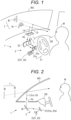
- Fig. 1 is a conceptual configuration diagram of an HUD device applied to an automobile.
- An HUD device 1 is disposed in a dashboard DB of the automobile, and image light L emitted from the HUD device 1 is projected onto a windshield WS of the automobile through an upper surface opening Ho of the dashboard.
- the projected image light L is reflected by the windshield WS and is directed to an occupant M such as a driver of the automobile.
- the image light L enters eyes of the occupant M, the occupant M can visually recognize a virtual image I of the image light in front of the automobile through the windshield WS.
- the image is displayed.
- the HUD device 1 includes an image display unit 2 and an optical system 3 that projects an image displayed on the image display unit 2 onto the windshield WS.
- the image display unit 2 can display a plurality of images, here, two images.
- the optical system 3 projects image light beams of the two images displayed on the image display unit 2 onto the windshield WS at different angles, respectively. Therefore, a plurality of image light beams L reflected by the windshield enters the eyes of the occupant M, and the occupant M can visually recognize a plurality of virtual images Ia and Ib.
- an image light beam La and an image light beam Lb of the two independent images displayed on the image display unit 2 are projected onto the windshield WS in respective optical paths aligned in a horizontal direction.
- the image light beams La and Lb are variously affected by being reflected by a convex mirror 31 and a concave mirror 32 of the optical system 3 and further by the windshield WS, and, when the image light beams enter the eyes of the occupant M, the occupant can visually recognize the virtual images Ia and Ib of the respective images in desired positions and inclinations.
- display is performed such that the virtual image Ia of a speed meter can be visually recognized on a left side through the windshield WS, and the virtual image Ib of navigation can be visually recognized on a right side at a position deeper than that of the virtual image Ia.
- Fig. 2 is a schematic view of the HUD device 1 as viewed from a side direction.
- the optical system 3 includes the first reflection unit 31 that reflects the image light L of the image displayed on the image display unit 2 and the second reflection unit 32 that further reflects the light reflected by the first reflection unit 31 and projects the light onto the windshield WS.
- the first reflection unit 31 includes a convex mirror
- the second reflection unit 32 includes a concave mirror.
- the convex mirror 31 includes two convex mirrors 31a and 31b of which reflecting surfaces are different in radius of curvature.
- the image light beam La is reflected by the convex mirror 31a having a predetermined radius of curvature
- the image light beam Lb is reflected by the convex mirror 3 1b having a radius of curvature larger than that of the convex mirror 31a.
- the convex mirror 31a may be disposed at a position closer to the image display unit 2 than the convex mirror 3 1b to display the virtual image Ib at a position deeper than the virtual image Ia.
- the concave mirror 32 has a spherical surface, aspherical surface, or free-form surface having a curvature that achieves a required focal length. Aberration in the concave mirror 32 is improved by the convex mirror 31, and the focal length of the concave mirror 32 is substantially extended.
- the HUD device 1 is configured such that the image displayed on the image display unit 2 is placed within the focal length of the concave mirror 32. Therefore, the occupant M can visually recognize the virtual image I of the displayed image.
- Fig. 3 is an exploded perspective view illustrating a schematic configuration of the image display unit 2 according to a first embodiment.
- the image display unit 2 includes a liquid crystal device 21 and a prism sheet 22.
- the liquid crystal device 21 can display a desired image on an image display surface 23 and can be an existing liquid crystal device.
- the liquid crystal device 21 is such that the image display surface 23 includes a large number of pixels 24 arranged in a matrix direction.
- the image display surface 23 is divided into two regions in a row direction, and an A image Oa is displayed in one A region 23a, whereas a B image Ob is displayed in the other B region 23b.
- the A image Oa corresponds to the speed meter image
- the B image Ob corresponds to the navigation image.
- the liquid crystal device 21 is configured as a color liquid crystal device in which each pixel 24 includes three RGB subpixels 25 (25r, 25g, and 25b), and can therefore display a color image.
- the subpixels 25 are arranged side by side in the row direction.
- the plurality of pixels 24 arranged side by side in a column direction is in the same array as the RGB subpixels 25 (25r, 25g, and 25b).
- the actual pixels 24 have an extremely small size, and the A image Oa and the B image Ob are displayed by the minute pixels 24.
- Fig. 3 illustrates the pixels with a large size in order to describe a correspondence with the prism sheet 22.
- the prism sheet 22 includes a sheet made from a material having light transmittance and a refractive index and also having high transferability such as, but not limited to, resin.
- a large number of wedge-shaped (triangular) microprisms 26 are arrayed and integrally formed on a plane.
- the microprisms 26 include two types of microprisms each having an emission surface inclined in the row direction, i.e., a plurality of A microprisms 26a and a plurality of B microprisms 26b.
- the A microprisms 26a and the B microprisms 26b are disposed corresponding to the pixels 24 of the liquid crystal device 21.
- each microprism is disposed for each column of the pixels 24 arranged in a matrix and forms a so-called lenticular lens.
- the emission surfaces of the A microprism 26a and the B microprism 26b are formed as inclined surfaces of which inclination angles are the same but inclination directions are opposite in the row direction.
- Both the microprisms 26a and 26b have the same height dimension, that is, the same thickness dimension.
- the prism sheet 22 has a flat back surface, and the back surface is attached to the image display surface 23 of the liquid crystal device 21 while being in close contact with the image display surface with a predetermined positional relationship. That is, the plurality of A microprisms 26a and the plurality of B microprisms 26b are attached to the pixels 24 in each column of the liquid crystal device 21 while being positioned with respect to the pixels. Therefore, the image light beams La emitted from a pixel group of the A region 21a are refracted by the A microprisms 26a outward (leftward in Fig. 4 ) with respect to the center and are emitted from the emission surfaces.
- the image light beams Lb emitted from a pixel group of the B region 21b are refracted by the B microprisms 26b outward (rightward in Fig. 4 ) with respect to the center and are emitted from the emission surfaces.
- the B microprisms 26b outward (rightward in Fig. 4 ) with respect to the center and are emitted from the emission surfaces.
- only either the image light beams La or the image light beams Lb may be directed outward.
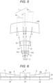
- Fig. 5 is a schematic plan view for describing a form of image display in the HUD device 1.
- the image light beams La of the A image Oa (hereinafter, the A image light beams) are deflected leftward with respect to the optical axis by the A microprisms 26a
- the image light beams Lb of the B image Ob (hereinafter, the B image light beams) are deflected rightward with respect to the optical axis by the B microprisms 26b.
- an optical path through which light emitted vertically from the center of the liquid crystal display surface 23 passes is defined as an optical axis Lx.
- the A image light beams La and the B image light beams Lb deflected in opposite directions are reflected by the convex mirrors 31a and 31b, are then reflected by the concave mirror 32, and are thereafter projected onto the windshield WS. Therefore, when those image light beams La and Lb are reflected by the windshield WS and enter the eyes of the occupant, the occupant can visually recognize the A image Oa and the B image Ob, here, the virtual images of the speed meter image and the navigation image, that is, the A virtual image Ia and the B virtual image Ib. Thus, each image is displayed. At this time, the B virtual image Ib is displayed at a position deeper than the A virtual image Ia.
- the image light beams of the A image Oa and the B image Ob to be displayed are displayed on the image display surface 23 while being close to each other in the image display unit 2 including the liquid crystal device 21, the A virtual image Ia and the B virtual image Ib are also displayed while being close to each other.
- both the images may not be visually recognized separately.
- the prism sheet 22 is disposed on the image display surface 23 of the liquid crystal device 21, the image light beams La and Lb of the images Oa and Ob can be deflected by the prism sheet 22 so as to have a desired angle difference.
- the A virtual image Ia and the B virtual image Ib can be visually recognized at a desired interval. This makes it possible to perform preferable display.
- the angle difference can be changed by adjusting an angle of the emission surfaces of the A microprisms 26a or the B microprisms 26b. Therefore, the A virtual image Ia and the B virtual image Ib can be observed in arbitrary directions as viewed from the occupant. For example, directions of the A virtual image Ia and the B virtual image Ib can also be individually set by making the angles of the emission surfaces of the A microprisms 26a and the B microprism 26b different.
- the microprisms 26 are formed as one prism sheet 22, and thus, even in a case where the prism sheet is attached to the image display surface 23 of the liquid crystal device 21, a thickness dimension of the liquid crystal device 21, that is, a thickness dimension of the image display unit 2 is increased only by a thickness dimension of the prism sheet 22. Further, one microprism 26 is formed corresponding to one column of the pixels 24 of the liquid crystal device 21, and thus a dimension in the row direction is extremely small. Therefore, even in a case where the inclination angle of the emission surfaces of the microprisms 26 is increased in order to increase a deflection angle of image light, an increase in a thickness dimension of each microprism 26 can be extremely small. Accordingly, the thickness dimension of the prism sheet 22 can also be small, and the thickness dimension of the image display unit 2 is not significantly increased. Thus, a small HUD device is formed.
- the microprisms 26 including the A microprisms 26a and the B microprisms 26b can be manufactured as the prism sheet 22 by integral molding using a light-transmissive resin or the like.
- the microprisms 26 can be easily manufactured to have the dimensions of the pixels 24 or the subpixels 25.
- the microprisms 26 can be accurately positioned with respect to the corresponding pixels 24. Also from this point, the image display unit 2 can be easily manufactured.
- Fig. 6 is a cross-sectional view of a first modification example of the image display unit 2. Parts equivalent to those in the first embodiment are denoted by the same reference signs.
- one microprism 26c of the prism sheet 22 is disposed for each two columns of the pixels 24 of the liquid crystal device 21. That is, one microprism 26c is arranged to face two columns of the pixels 24, and one microprism 26c deflects pixel light of the two columns of the pixels 24 facing the microprism 26c.
- the virtual images of the A image and the B image can be visually recognized at a required interval. Further, because the image light is deflected for each two columns of the pixels 24, it is possible to restrain inclination of the virtual images to be visually recognized, as compared with the technique of Patent Literature 1. Furthermore, in a case where the first modification example is applied to a liquid crystal device of the same standard, the number of microprisms 26c formed on the prism sheet 22 can be reduced. Therefore, the prism sheet 22 can be easily manufactured.
- the first modification example when an inclination angle of emission surfaces of the microprisms 26c increases, a height dimension of the microprisms 26c, that is, the thickness dimension of the prism sheet 22 also increases.
- the first modification example is suitable for an HUD device that deflects image light at a relatively small angle.
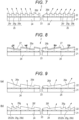
- Fig. 7 is a cross-sectional view of a second modification example of the image display unit 2.
- microprisms 26d are formed in the prism sheet 22 so as to correspond to the three RGB subpixels 25 (25r, 25g, and 25b) included in one pixel 24 of the liquid crystal device 21. That is, image light beams of the three subpixels 25r, 25g, and 25b of one pixel 24 are independently deflected by the microprisms 26d.
- the virtual images of the A image and the B image can be observed at a desired interval. Further, because the image light is deflected for each subpixel, it is possible to restrain inclination of the virtual images to be visually recognized.
- a dimension in the row direction of the microprisms 26d can be reduced corresponding to a dimension of the subpixel 25, and thus, even in a case where an inclination angle of emission surfaces is increased, it is possible to restrain an increase in a height dimension of the microprisms 26d, that is, an increase in the thickness dimension of the prism sheet 22. Therefore, even in a case where the modification example is applied to an HUD device that requires a larger interval dimension between the virtual images of the A image and the B image, it is possible to prevent an increase in the thickness dimension of the image display unit 2.
- Fig. 8 is a cross-sectional view of a third modification example of the image display unit 2.
- an optical layer 27 that radiates or diffuses image light to be emitted is laminated on the emission surfaces of the A microprisms 26a and the B microprisms 26b of the first embodiment.
- the optical layer 27 may be formed as a concave lens microprism that radiates light.
- a luminous flux of image light emitted from each of the microprisms 26a and 26b is spread on the optical layer 27. Therefore, even in a case where image light is emitted from only a part of the RGB subpixels 25 in each pixel 24, it is possible to obtain a luminous flux substantially equal to that in a case where image light is emitted from one pixel 24, that is, three subpixels 25r, 25g, and 25b. This makes it possible to visually recognize a virtual image with uniform brightness.
- one microprism may be disposed for each pixel of the pixels arranged in a matrix as long as the prism sheet can be finely processed or manufactured.
- one microprism may be disposed for each subpixel.
- one microprism may be disposed for each group including a plurality of pixels in the row direction and/or the column direction.
- a microprism may be disposed to face only a part of all the pixels included in the image display surface. In this case, image light of the other pixels is not deflected and is emitted in a vertical direction of the image display surface.
- the liquid crystal device may display three different images on the image display surface, and the prism sheet may include three different microprisms having different inclination angles, such as A microprisms, B microprisms, and C microprisms.
- the A microprisms deflect A image light leftward
- the B microprisms deflect B image light rightward
- the C microprisms do not deflect C image light. This makes it possible to display three different images side by side in the horizontal direction.
- the liquid crystal device may display four or more images.
- the liquid crystal device 21 in the HUD device including the liquid crystal device 21 as in the present invention, image light emitted from the image display surface 23 of the liquid crystal device 21 is required to be emitted from the image display surface 23 as a substantially parallel luminous flux in a substantially vertical direction. Therefore, contrast in an image to be displayed may be reduced. That is, as a characteristic of the liquid crystal device 21, in a case where light is obliquely incident on the liquid crystal device 21, the liquid crystal device 21 substantially blocks the light or substantially transmits the light because elements in the liquid crystal device 21 are not in an appropriate positional relationship, and light leakage occurs at that time. When the light leakage occurs, a brightness ratio between white and black that can be displayed by the liquid crystal device, that is, contrast decreases.
- the HUD device 1 of the first embodiment light emitted from the image display unit 2 is deflected in the same direction in the same display region.
- image light is vertically emitted at the center of the image display surface 23, and image light at an end portion thereof spreads outward with respect to the optical axis Lx. Therefore, a virtual image at the end portion is displayed by light traveling obliquely through a liquid crystal, and the contrast decreases due to the above-described liquid crystal characteristic.
- Fig. 10 schematically illustrates an optical path of light emitted from the liquid crystal device 21, in a case where the center of the image display surface 23 of the liquid crystal device 21 is set to the optical axis Lx, an image light beam Lc is vertical at the center of the image display surface 23.
- the above-described contrast is improved by controlling deflection of image light beams Ls emitted from a region away from the optical axis Lx, that is, a peripheral region away from the center of the image display surface 23.
- an inclination angle of emission surfaces of microprisms corresponding to the peripheral region of the image display surface 23 is made relatively larger than an inclination angle of emission surfaces of microprisms corresponding to the center thereof.
- Fig. 9(a) is a cross-sectional view of a first example of the image display unit 2 according to the second embodiment.
- one microprism 26 is disposed for one column of the pixels 24 of the liquid crystal device as in the first embodiment, but an inclination angle of emission surfaces of microprisms 26e in a region away from the optical axis of the image display surface 23 is made larger than an inclination angle of emission surfaces of the microprisms 26d in a region close to the optical axis.
- microprisms 26f corresponding to the pixels 24 may be disposed in the region close to the optical axis, and microprisms 26g corresponding to the subpixels 25 (25r, 25g, and 25b) may be disposed in the region away from the optical axis.
- the image display unit only needs to emit image light and thus may be formed for an intermediate image in an optical system including a DMD device that includes micromirrors arranged in a matrix to selectively reflect light of a light source and emit image light.
- the image display unit may be formed as an organic EL.
- the first reflection unit of the optical system is not limited to the convex mirror and may be a flat mirror. Optical members other than the concave mirror may be omitted as long as a failure such as interference of the HUD device with another device of the automobile does not occur.
- At least one of the optical systems 3 may be divided into two or more and may be formed as dedicated optical systems for a plurality of images.
- the windshield of the present invention is not limited to the windshield of the automobile described in the embodiments and may be a part of a vehicle body, such as a light-transmissive window provided in a vehicle.
Landscapes
- Engineering & Computer Science (AREA)
- Chemical & Material Sciences (AREA)
- Combustion & Propulsion (AREA)
- Transportation (AREA)
- Mechanical Engineering (AREA)
- Physics & Mathematics (AREA)
- General Physics & Mathematics (AREA)
- Optics & Photonics (AREA)
- Instrument Panels (AREA)
Abstract
Description
- The present invention relates to a display device mounted on a vehicle such as an automobile, and more particularly to a head-up display device (hereinafter, the HUD device).
- As the HUD device, there has been proposed a device that projects light forming an image onto a windshield of an automobile so that an occupant such as a driver can visually recognize a virtual image of the image with reflected light thereof. Hereinafter, making a virtual image visually recognizable will also be referred to as displaying an image. There has also been proposed an HUD device that can display a plurality of images. For example,
Patent Literature 1 proposes an HUD device that emits light beams of a plurality of images (hereinafter, image light beams) displayed on an image display unit including a liquid crystal display (hereinafter, a liquid crystal device), in different directions by using an optical element, thereby independently displaying each image. - That is, in the technique of
Patent Literature 1, the optical element including a light guide is disposed on a display surface of the image display unit, and an emission surface from which image light beams are emitted through the optical element is inclined, whereby the image light beams emitted from the display surface of the image display unit are refracted. Then, angles of refraction, that is, directions of deflection of the plurality of image light beams are made different, and thus each image is displayed. - PATENT LITERATURE 1:
JP-A-2018-173589 - In the technique of
Patent Literature 1, the emission surface of the light guide forming the optical element is formed as one continuous inclined surface corresponding to an image. Therefore, when a plurality of images is displayed by using such an optical element, each image to be displayed can be inclined and shifted in a depth direction. However, at a boundary of a prism that creates a plurality of image light beams, an image light space spreading considerably from the image display unit becomes uncontrollable light. This tends to reduce quality of a virtual image. - This problem particularly tends to occur in a case where display images are close to each other. However, in order to increase an interval between a plurality of images to be displayed, a large image display unit is required. This leads not only to an increase in cost but also to an increase in an angle of deflection of image light. This also leads to an increase in an angle of inclination of the emission surface. Therefore, a dimension of the optical element in an optical axis direction is increased to increase a thickness dimension of the optical element, and thus a thickness dimension of the image display unit including the optical element is also increased.
- An object of the present invention is to provide a vehicle display device that displays a plurality of images without inclining the images and includes a thinned image display unit to achieve reduction in size.
- The present invention is a vehicle display device including: an image display unit including a plurality of pixels for displaying an image on an image display surface; and an optical system that projects image light beams of the displayed image onto a windshield of a vehicle, the vehicle display device making a virtual image of the image visually recognizable by using light reflected by the windshield. The image display unit includes a prism sheet disposed on the image display surface, and the prism sheet includes a plurality of microprisms that is disposed to face the plurality of pixels forming the one image and that individually deflects the image light beams emitted from the pixels.
- In the present invention, the optical system includes a concave mirror that reflects the image light beams emitted from the image display unit toward the windshield. Further, the image display unit is capable of displaying a plurality of images on the image display surface, and the microprisms deflect image light beams at the same angle for the same image and deflect image light beams at a different angle for a different image. It is preferable that the microprisms in the same image region deflect the image light beams at a certain same angle and that the microprisms in another image region different from the image region deflect the image light beams at another same angle in the another image region, the another same angle being different from the certain same angle.
- As a preferred form of the present invention, the plurality of pixels on the image display surface is arranged in a matrix, and each of the plurality of microprisms is arranged to face one column of the pixels or a plurality of columns of the pixels. Alternatively, the pixel of the image display surface includes a plurality of subpixels, and the microprisms are arranged to face the subpixels. Further, a deflection angle of the microprisms disposed in a region away from an optical axis of the optical system is larger than a deflection angle of the microprisms disposed in a region close to the optical axis.
- In the present invention, it is preferable that the plurality of microprisms be integrally formed on the same prism sheet. It is also preferable that the microprisms include an optical layer that radiates or diffuses light on an emission surface from which the image light beams are emitted.
- According to the present invention, the image light beams emitted from the plurality of pixels are individually deflected by the microprisms of the prism sheet disposed on the image display surface. This makes it possible to control a direction of the image light beams projected onto the windshield to control an image to be displayed. Therefore, there is provided the vehicle display device that displays the plurality of images in a suitable state and achieves reduction in size of the image display unit.
-
-
Fig. 1 is a conceptual configuration diagram of an HUD device. -
Fig. 2 is a schematic view of the HUD device as viewed from the side. -
Fig. 3 is an exploded perspective view of a schematic configuration of an image display unit. -
Fig. 4 is a cross-sectional view of a schematic configuration of the image display unit. -
Fig. 5 is a schematic plan view for describing a form of image display. -
Fig. 6 is a cross-sectional view of a schematic configuration of a first modification example of the image display unit. -
Fig. 7 is a cross-sectional view of a schematic configuration of a second modification example of the image display unit. -
Fig. 8 is a cross-sectional view of a schematic configuration of a third modification example of the image display unit. -
Fig. 9 is a cross-sectional view of a schematic configuration of a second embodiment of the image display unit. -
Fig. 10 is a schematic optical path diagram for describing an operation of the second embodiment. - Next, embodiments of the present invention will be described with reference to the drawings.
Fig. 1 is a conceptual configuration diagram of an HUD device applied to an automobile. AnHUD device 1 is disposed in a dashboard DB of the automobile, and image light L emitted from theHUD device 1 is projected onto a windshield WS of the automobile through an upper surface opening Ho of the dashboard. The projected image light L is reflected by the windshield WS and is directed to an occupant M such as a driver of the automobile. When the image light L enters eyes of the occupant M, the occupant M can visually recognize a virtual image I of the image light in front of the automobile through the windshield WS. Thus, the image is displayed. - The
HUD device 1 includes animage display unit 2 and anoptical system 3 that projects an image displayed on theimage display unit 2 onto the windshield WS. Theimage display unit 2 can display a plurality of images, here, two images. Theoptical system 3 projects image light beams of the two images displayed on theimage display unit 2 onto the windshield WS at different angles, respectively. Therefore, a plurality of image light beams L reflected by the windshield enters the eyes of the occupant M, and the occupant M can visually recognize a plurality of virtual images Ia and Ib. - That is, an image light beam La and an image light beam Lb of the two independent images displayed on the
image display unit 2 are projected onto the windshield WS in respective optical paths aligned in a horizontal direction. The image light beams La and Lb are variously affected by being reflected by aconvex mirror 31 and aconcave mirror 32 of theoptical system 3 and further by the windshield WS, and, when the image light beams enter the eyes of the occupant M, the occupant can visually recognize the virtual images Ia and Ib of the respective images in desired positions and inclinations. In this example, display is performed such that the virtual image Ia of a speed meter can be visually recognized on a left side through the windshield WS, and the virtual image Ib of navigation can be visually recognized on a right side at a position deeper than that of the virtual image Ia. -
Fig. 2 is a schematic view of theHUD device 1 as viewed from a side direction. Theoptical system 3 includes thefirst reflection unit 31 that reflects the image light L of the image displayed on theimage display unit 2 and thesecond reflection unit 32 that further reflects the light reflected by thefirst reflection unit 31 and projects the light onto the windshield WS. Thefirst reflection unit 31 includes a convex mirror, and thesecond reflection unit 32 includes a concave mirror. Here, theconvex mirror 31 includes twoconvex mirrors convex mirror 31a having a predetermined radius of curvature, and the image light beam Lb is reflected by theconvex mirror 3 1b having a radius of curvature larger than that of theconvex mirror 31a. In a case where theconvex mirror 31a and theconvex mirror 31b have the same curvature, theconvex mirror 31a may be disposed at a position closer to theimage display unit 2 than theconvex mirror 3 1b to display the virtual image Ib at a position deeper than the virtual image Ia. - The
concave mirror 32 has a spherical surface, aspherical surface, or free-form surface having a curvature that achieves a required focal length. Aberration in theconcave mirror 32 is improved by theconvex mirror 31, and the focal length of theconcave mirror 32 is substantially extended. TheHUD device 1 is configured such that the image displayed on theimage display unit 2 is placed within the focal length of theconcave mirror 32. Therefore, the occupant M can visually recognize the virtual image I of the displayed image. -
Fig. 3 is an exploded perspective view illustrating a schematic configuration of theimage display unit 2 according to a first embodiment. Theimage display unit 2 includes aliquid crystal device 21 and aprism sheet 22. Theliquid crystal device 21 can display a desired image on animage display surface 23 and can be an existing liquid crystal device. Although briefly illustrated inFig. 3 , theliquid crystal device 21 is such that theimage display surface 23 includes a large number ofpixels 24 arranged in a matrix direction. Theimage display surface 23 is divided into two regions in a row direction, and an A image Oa is displayed in one Aregion 23a, whereas a B image Ob is displayed in theother B region 23b. Here, the A image Oa corresponds to the speed meter image, and the B image Ob corresponds to the navigation image. - The
liquid crystal device 21 is configured as a color liquid crystal device in which eachpixel 24 includes three RGB subpixels 25 (25r, 25g, and 25b), and can therefore display a color image. The subpixels 25 are arranged side by side in the row direction. The plurality ofpixels 24 arranged side by side in a column direction is in the same array as the RGB subpixels 25 (25r, 25g, and 25b). Note that theactual pixels 24 have an extremely small size, and the A image Oa and the B image Ob are displayed by theminute pixels 24. However,Fig. 3 illustrates the pixels with a large size in order to describe a correspondence with theprism sheet 22. - The
prism sheet 22 includes a sheet made from a material having light transmittance and a refractive index and also having high transferability such as, but not limited to, resin. A large number of wedge-shaped (triangular) microprisms 26 are arrayed and integrally formed on a plane. Themicroprisms 26 include two types of microprisms each having an emission surface inclined in the row direction, i.e., a plurality of Amicroprisms 26a and a plurality ofB microprisms 26b. TheA microprisms 26a and theB microprisms 26b are disposed corresponding to thepixels 24 of theliquid crystal device 21. Here, each microprism is disposed for each column of thepixels 24 arranged in a matrix and forms a so-called lenticular lens. The emission surfaces of theA microprism 26a and theB microprism 26b are formed as inclined surfaces of which inclination angles are the same but inclination directions are opposite in the row direction. Both themicroprisms - As
Fig. 4 illustrates a cross-sectional configuration of theimage display unit 2, theprism sheet 22 has a flat back surface, and the back surface is attached to theimage display surface 23 of theliquid crystal device 21 while being in close contact with the image display surface with a predetermined positional relationship. That is, the plurality of Amicroprisms 26a and the plurality ofB microprisms 26b are attached to thepixels 24 in each column of theliquid crystal device 21 while being positioned with respect to the pixels. Therefore, the image light beams La emitted from a pixel group of the A region 21a are refracted by theA microprisms 26a outward (leftward inFig. 4 ) with respect to the center and are emitted from the emission surfaces. The image light beams Lb emitted from a pixel group of the B region 21b are refracted by theB microprisms 26b outward (rightward inFig. 4 ) with respect to the center and are emitted from the emission surfaces. However, in a case where a distance between the image light beams La and Lb increases as the image light beams travel from the microprisms toward the convex surfaces, only either the image light beams La or the image light beams Lb may be directed outward. -
Fig. 5 is a schematic plan view for describing a form of image display in theHUD device 1. When the A image and the B image are displayed on theimage display unit 2, as illustrated inFig. 4 , the image light beams La of the A image Oa (hereinafter, the A image light beams) are deflected leftward with respect to the optical axis by theA microprisms 26a, and the image light beams Lb of the B image Ob (hereinafter, the B image light beams) are deflected rightward with respect to the optical axis by theB microprisms 26b. Note that an optical path through which light emitted vertically from the center of the liquidcrystal display surface 23 passes is defined as an optical axis Lx. - The A image light beams La and the B image light beams Lb deflected in opposite directions are reflected by the
convex mirrors concave mirror 32, and are thereafter projected onto the windshield WS. Therefore, when those image light beams La and Lb are reflected by the windshield WS and enter the eyes of the occupant, the occupant can visually recognize the A image Oa and the B image Ob, here, the virtual images of the speed meter image and the navigation image, that is, the A virtual image Ia and the B virtual image Ib. Thus, each image is displayed. At this time, the B virtual image Ib is displayed at a position deeper than the A virtual image Ia. - Conventionally, when the image light beams of the A image Oa and the B image Ob to be displayed are displayed on the
image display surface 23 while being close to each other in theimage display unit 2 including theliquid crystal device 21, the A virtual image Ia and the B virtual image Ib are also displayed while being close to each other. Thus, both the images may not be visually recognized separately. In theHUD device 1, because theprism sheet 22 is disposed on theimage display surface 23 of theliquid crystal device 21, the image light beams La and Lb of the images Oa and Ob can be deflected by theprism sheet 22 so as to have a desired angle difference. - Therefore, the A virtual image Ia and the B virtual image Ib can be visually recognized at a desired interval. This makes it possible to perform preferable display. The angle difference can be changed by adjusting an angle of the emission surfaces of the
A microprisms 26a or theB microprisms 26b. Therefore, the A virtual image Ia and the B virtual image Ib can be observed in arbitrary directions as viewed from the occupant. For example, directions of the A virtual image Ia and the B virtual image Ib can also be individually set by making the angles of the emission surfaces of theA microprisms 26a and theB microprism 26b different. - The
microprisms 26 are formed as oneprism sheet 22, and thus, even in a case where the prism sheet is attached to theimage display surface 23 of theliquid crystal device 21, a thickness dimension of theliquid crystal device 21, that is, a thickness dimension of theimage display unit 2 is increased only by a thickness dimension of theprism sheet 22. Further, onemicroprism 26 is formed corresponding to one column of thepixels 24 of theliquid crystal device 21, and thus a dimension in the row direction is extremely small. Therefore, even in a case where the inclination angle of the emission surfaces of themicroprisms 26 is increased in order to increase a deflection angle of image light, an increase in a thickness dimension of eachmicroprism 26 can be extremely small. Accordingly, the thickness dimension of theprism sheet 22 can also be small, and the thickness dimension of theimage display unit 2 is not significantly increased. Thus, a small HUD device is formed. - The
microprisms 26 including theA microprisms 26a and theB microprisms 26b can be manufactured as theprism sheet 22 by integral molding using a light-transmissive resin or the like. Thus, themicroprisms 26 can be easily manufactured to have the dimensions of thepixels 24 or thesubpixels 25. Further, in a case where theprism sheet 22 is positioned with respect to theliquid crystal device 21, themicroprisms 26 can be accurately positioned with respect to the correspondingpixels 24. Also from this point, theimage display unit 2 can be easily manufactured. -
Fig. 6 is a cross-sectional view of a first modification example of theimage display unit 2. Parts equivalent to those in the first embodiment are denoted by the same reference signs. In the first modification example, onemicroprism 26c of theprism sheet 22 is disposed for each two columns of thepixels 24 of theliquid crystal device 21. That is, onemicroprism 26c is arranged to face two columns of thepixels 24, and onemicroprism 26c deflects pixel light of the two columns of thepixels 24 facing themicroprism 26c. - In the first modification example, as well as in the first embodiment, the virtual images of the A image and the B image can be visually recognized at a required interval. Further, because the image light is deflected for each two columns of the
pixels 24, it is possible to restrain inclination of the virtual images to be visually recognized, as compared with the technique ofPatent Literature 1. Furthermore, in a case where the first modification example is applied to a liquid crystal device of the same standard, the number ofmicroprisms 26c formed on theprism sheet 22 can be reduced. Therefore, theprism sheet 22 can be easily manufactured. Meanwhile, in the first modification example, when an inclination angle of emission surfaces of themicroprisms 26c increases, a height dimension of themicroprisms 26c, that is, the thickness dimension of theprism sheet 22 also increases. Thus, the first modification example is suitable for an HUD device that deflects image light at a relatively small angle. -
Fig. 7 is a cross-sectional view of a second modification example of theimage display unit 2. In this modification example,microprisms 26d are formed in theprism sheet 22 so as to correspond to the three RGB subpixels 25 (25r, 25g, and 25b) included in onepixel 24 of theliquid crystal device 21. That is, image light beams of the threesubpixels pixel 24 are independently deflected by themicroprisms 26d. - Also in the second modification example, the virtual images of the A image and the B image can be observed at a desired interval. Further, because the image light is deflected for each subpixel, it is possible to restrain inclination of the virtual images to be visually recognized. In the second modification example, a dimension in the row direction of the
microprisms 26d can be reduced corresponding to a dimension of thesubpixel 25, and thus, even in a case where an inclination angle of emission surfaces is increased, it is possible to restrain an increase in a height dimension of themicroprisms 26d, that is, an increase in the thickness dimension of theprism sheet 22. Therefore, even in a case where the modification example is applied to an HUD device that requires a larger interval dimension between the virtual images of the A image and the B image, it is possible to prevent an increase in the thickness dimension of theimage display unit 2. -
Fig. 8 is a cross-sectional view of a third modification example of theimage display unit 2. In the third modification example, anoptical layer 27 that radiates or diffuses image light to be emitted is laminated on the emission surfaces of theA microprisms 26a and theB microprisms 26b of the first embodiment. Alternatively, theoptical layer 27 may be formed as a concave lens microprism that radiates light. - In the third modification example, a luminous flux of image light emitted from each of the
microprisms optical layer 27. Therefore, even in a case where image light is emitted from only a part of the RGB subpixels 25 in eachpixel 24, it is possible to obtain a luminous flux substantially equal to that in a case where image light is emitted from onepixel 24, that is, threesubpixels - Although not illustrated, as a fourth modification example, one microprism may be disposed for each pixel of the pixels arranged in a matrix as long as the prism sheet can be finely processed or manufactured. Alternatively, one microprism may be disposed for each subpixel. Conversely, in a case where it is difficult to finely process or manufacture the prism sheet, one microprism may be disposed for each group including a plurality of pixels in the row direction and/or the column direction.
- Although not illustrated, as a fifth modification example, a microprism may be disposed to face only a part of all the pixels included in the image display surface. In this case, image light of the other pixels is not deflected and is emitted in a vertical direction of the image display surface.
- Although not illustrated, as a sixth modification example, the liquid crystal device may display three different images on the image display surface, and the prism sheet may include three different microprisms having different inclination angles, such as A microprisms, B microprisms, and C microprisms. For example, the A microprisms deflect A image light leftward, the B microprisms deflect B image light rightward, and the C microprisms do not deflect C image light. This makes it possible to display three different images side by side in the horizontal direction. The liquid crystal device may display four or more images.
- By the way, in the HUD device including the
liquid crystal device 21 as in the present invention, image light emitted from theimage display surface 23 of theliquid crystal device 21 is required to be emitted from theimage display surface 23 as a substantially parallel luminous flux in a substantially vertical direction. Therefore, contrast in an image to be displayed may be reduced. That is, as a characteristic of theliquid crystal device 21, in a case where light is obliquely incident on theliquid crystal device 21, theliquid crystal device 21 substantially blocks the light or substantially transmits the light because elements in theliquid crystal device 21 are not in an appropriate positional relationship, and light leakage occurs at that time. When the light leakage occurs, a brightness ratio between white and black that can be displayed by the liquid crystal device, that is, contrast decreases. - In the
HUD device 1 of the first embodiment, light emitted from theimage display unit 2 is deflected in the same direction in the same display region. However, in a small HUD device that displays a large virtual image, image light is vertically emitted at the center of theimage display surface 23, and image light at an end portion thereof spreads outward with respect to the optical axis Lx. Therefore, a virtual image at the end portion is displayed by light traveling obliquely through a liquid crystal, and the contrast decreases due to the above-described liquid crystal characteristic. - In the second embodiment, as
Fig. 10 schematically illustrates an optical path of light emitted from theliquid crystal device 21, in a case where the center of theimage display surface 23 of theliquid crystal device 21 is set to the optical axis Lx, an image light beam Lc is vertical at the center of theimage display surface 23. The above-described contrast is improved by controlling deflection of image light beams Ls emitted from a region away from the optical axis Lx, that is, a peripheral region away from the center of theimage display surface 23. That is, regarding microprisms formed on a prism sheet, an inclination angle of emission surfaces of microprisms corresponding to the peripheral region of theimage display surface 23 is made relatively larger than an inclination angle of emission surfaces of microprisms corresponding to the center thereof. -
Fig. 9(a) is a cross-sectional view of a first example of theimage display unit 2 according to the second embodiment. In the first example, onemicroprism 26 is disposed for one column of thepixels 24 of the liquid crystal device as in the first embodiment, but an inclination angle of emission surfaces ofmicroprisms 26e in a region away from the optical axis of theimage display surface 23 is made larger than an inclination angle of emission surfaces of themicroprisms 26d in a region close to the optical axis. With this configuration, a deflection angle of image light emitted from themicroprisms 26e in the region away therefrom is increased, but light traveling in a nearly vertical direction through the liquid crystal is used, and thus it is possible to provide high-quality display without causing a decrease in contrast. - In the second embodiment, as in a cross-sectional view of
Fig. 9(b) ,microprisms 26f corresponding to thepixels 24 may be disposed in the region close to the optical axis, andmicroprisms 26g corresponding to the subpixels 25 (25r, 25g, and 25b) may be disposed in the region away from the optical axis. With this configuration, it is possible to prevent an increase in a height dimension of themicroprisms 26g and to prevent an increase in the thickness dimension of theprism sheet 22, as compared with a case where the inclination angle is increased as in themicroprisms 26e disposed for the respective pixels as illustrated inFig. 9(a) . - In the embodiments and the modification examples described above, there have been described examples where a plurality of images is displayed side by side in the horizontal direction. However, the present invention can be similarly applied to a case where virtual images are displayed side by side in the vertical direction. In this case, image light may be deflected in the column direction by the microprisms formed on the prism sheet.
- In the present invention, the image display unit only needs to emit image light and thus may be formed for an intermediate image in an optical system including a DMD device that includes micromirrors arranged in a matrix to selectively reflect light of a light source and emit image light. Alternatively, the image display unit may be formed as an organic EL. The first reflection unit of the optical system is not limited to the convex mirror and may be a flat mirror. Optical members other than the concave mirror may be omitted as long as a failure such as interference of the HUD device with another device of the automobile does not occur. At least one of the
optical systems 3 may be divided into two or more and may be formed as dedicated optical systems for a plurality of images. - The windshield of the present invention is not limited to the windshield of the automobile described in the embodiments and may be a part of a vehicle body, such as a light-transmissive window provided in a vehicle.
- The present international application claims priority based on
Japanese Patent Application No. 2020-077022 filed on April 24, 2020 Japanese Patent Application No. 2020-077022 - The above description of specific embodiments of the present invention has been presented for the purpose of illustration. The description is not intended to be exhaustive or to limit the present invention to the described forms. It is obvious to those skilled in the art that many modifications and changes can be made according to the above description.
-
- 1
- HUD device
- 2
- Image display unit
- 3
- Optical system
- 21
- Liquid crystal device
- 22
- Prism sheet
- 23
- Image display surface
- 24
- Pixel
- 25 (25r, 25g, 25b)
- Subpixel
- 26 (26a, 26b, 26c, 26d, 26e, 26f, 26g)
- Microprism
- 27
- Optical layer
- 31 (31a, 31b)
- First reflection unit (convex mirror)
- 32
- Second reflection unit (concave mirror)
- WS
- Windshield
- Oa, Ob
- Image
- I, Ia, Ib
- Virtual image
- L, La,
- Lb Image light, image light beam
- Lx
- Optical axis
Claims (10)
- A vehicle display device comprising:an image display unit including a plurality of pixels for displaying an image on an image display surface; andan optical system that projects image light beams of the displayed image onto a windshield of a vehicle,the vehicle display device making a virtual image of the image visually recognizable by using light reflected by the windshield,wherein the image display unit includes a prism sheet disposed on the image display surface, andthe prism sheet includes a plurality of microprisms that is disposed to face the plurality of pixels forming the one image and that individually deflects the image light beams emitted from the pixels.
- The vehicle display device according to claim 1, wherein
the optical system includes a concave mirror that reflects the image light beams emitted from the image display unit toward the windshield. - The vehicle display device according to claim 2, whereinthe image display unit is capable of displaying a plurality of images on the image display surface, andthe microprisms in a same image region deflect the image light beams at a certain same angle, and the microprisms in another image region different from the image region deflect the image light beams at another same angle in the another image region, the another same angle being different from the certain same angle.
- The vehicle display device according to claim 3, whereinthe plurality of pixels on the image display surface is arranged in a matrix, andeach of the plurality of microprisms is arranged to face one column of the pixels or a plurality of columns of the pixels.
- The vehicle display device according to claim 3, whereinthe pixel includes a plurality of subpixels, andthe microprisms are arranged to face the subpixels.
- The vehicle display device according to claim 5, wherein
the microprisms are configured such that a deflection angle of the microprisms arranged to face the pixels is smaller than a deflection angle of the microprisms arranged to face the subpixels. - The vehicle display device according to any one of claims 1 to 6, wherein
the microprisms are configured such that a deflection angle of the microprisms disposed in a region away from an optical axis of the optical system is larger than a deflection angle of the microprisms disposed in a region close to the optical axis. - The vehicle display device according to any one of claims 1 to 7, wherein
the microprisms include an inclined emission surface that refracts and emits the image light beams and are configured such that an inclination angle of an emission surface of the microprism having a large deflection angle is larger than an inclination angle of an emission surface of the microprism having a small deflection angle. - The vehicle display device according to any one of claims 1 to 8, wherein
the plurality of microprisms is integrally formed on a same prism sheet. - The vehicle display device according to claim 8 or 9, wherein
the microprisms include an optical layer that radiates or diffuses light on the emission surface from which the image light beams are emitted.
Applications Claiming Priority (2)
| Application Number | Priority Date | Filing Date | Title |
|---|---|---|---|
| JP2020077022A JP7497201B2 (en) | 2020-04-24 | 2020-04-24 | Vehicle display device |
| PCT/JP2021/015882 WO2021215400A1 (en) | 2020-04-24 | 2021-04-19 | Vehicular display device |
Publications (2)
| Publication Number | Publication Date |
|---|---|
| EP4141516A1 true EP4141516A1 (en) | 2023-03-01 |
| EP4141516A4 EP4141516A4 (en) | 2023-11-01 |
Family
ID=78269253
Family Applications (1)
| Application Number | Title | Priority Date | Filing Date |
|---|---|---|---|
| EP21793206.0A Withdrawn EP4141516A4 (en) | 2020-04-24 | 2021-04-19 | VEHICLE DISPLAY DEVICE |
Country Status (4)
| Country | Link |
|---|---|
| EP (1) | EP4141516A4 (en) |
| JP (1) | JP7497201B2 (en) |
| CN (1) | CN115362406A (en) |
| WO (1) | WO2021215400A1 (en) |
Cited By (1)
| Publication number | Priority date | Publication date | Assignee | Title |
|---|---|---|---|---|
| EP4481468A4 (en) * | 2022-03-30 | 2025-05-28 | Huawei Technologies Co., Ltd. | Head-up display apparatus, head-up display method, and vehicle |
Family Cites Families (18)
| Publication number | Priority date | Publication date | Assignee | Title |
|---|---|---|---|---|
| JPH07340Y2 (en) * | 1990-02-27 | 1995-01-11 | 矢崎総業株式会社 | Reflective display device for vehicles |
| JPH11133403A (en) * | 1997-10-30 | 1999-05-21 | Casio Comput Co Ltd | Display element |
| TW448312B (en) * | 2000-11-02 | 2001-08-01 | Ind Tech Res Inst | Microprism automatic stereoscopic display |
| CN101750772A (en) * | 2008-12-11 | 2010-06-23 | 嘉威光电股份有限公司 | Display method of multiple pictures |
| JP6031741B2 (en) * | 2011-10-06 | 2016-11-24 | 日本精機株式会社 | Display device |
| CN103292219A (en) * | 2013-06-04 | 2013-09-11 | 北京京东方光电科技有限公司 | Backlight module and display device |
| JP6409015B2 (en) * | 2016-03-29 | 2018-10-17 | 矢崎総業株式会社 | Projection display device for vehicle |
| JP2018095157A (en) * | 2016-12-15 | 2018-06-21 | アルプス電気株式会社 | On-vehicle display device |
| EP3557307B1 (en) * | 2016-12-15 | 2025-03-26 | Dualitas Ltd. | Image display device |
| JP6900666B2 (en) * | 2016-12-15 | 2021-07-07 | 大日本印刷株式会社 | Dimming system for mobiles |
| KR101909374B1 (en) * | 2017-02-23 | 2018-10-17 | 엘지전자 주식회사 | Head up display for vehicle |
| CN107247361A (en) * | 2017-08-14 | 2017-10-13 | 京东方科技集团股份有限公司 | A kind of bore hole 3D display devices and liquid crystal display device |
| JP6711337B2 (en) * | 2017-09-07 | 2020-06-17 | 株式会社デンソー | Head-up display device and image projection unit |
| CN108287388A (en) * | 2018-02-23 | 2018-07-17 | 京东方科技集团股份有限公司 | Light guide plate, backlight module, display device and its driving method |
| US20210088711A1 (en) * | 2018-03-28 | 2021-03-25 | 3M Innovative Properties Company | Wedge lightguide |
| JP7122673B2 (en) * | 2018-06-29 | 2022-08-22 | パナソニックIpマネジメント株式会社 | display, display system, moving object |
| JP6587300B1 (en) | 2018-11-05 | 2019-10-09 | Necプラットフォームズ株式会社 | Product imaging apparatus, product imaging method, and image recognition POS system |
| CN210323443U (en) * | 2019-09-29 | 2020-04-14 | 长沙湘计海盾科技有限公司 | Composite wide-half-brightness-angle optical brightness enhancement film |
-
2020
- 2020-04-24 JP JP2020077022A patent/JP7497201B2/en active Active
-
2021
- 2021-04-19 WO PCT/JP2021/015882 patent/WO2021215400A1/en not_active Ceased
- 2021-04-19 CN CN202180025396.3A patent/CN115362406A/en active Pending
- 2021-04-19 EP EP21793206.0A patent/EP4141516A4/en not_active Withdrawn
Cited By (1)
| Publication number | Priority date | Publication date | Assignee | Title |
|---|---|---|---|---|
| EP4481468A4 (en) * | 2022-03-30 | 2025-05-28 | Huawei Technologies Co., Ltd. | Head-up display apparatus, head-up display method, and vehicle |
Also Published As
| Publication number | Publication date |
|---|---|
| JP2021173854A (en) | 2021-11-01 |
| CN115362406A (en) | 2022-11-18 |
| JP7497201B2 (en) | 2024-06-10 |
| EP4141516A4 (en) | 2023-11-01 |
| WO2021215400A1 (en) | 2021-10-28 |
Similar Documents
| Publication | Publication Date | Title |
|---|---|---|
| US11294173B2 (en) | Display device and head-up display device | |
| US10859826B2 (en) | Head-up display device | |
| US10534112B2 (en) | Microlens array, image display apparatus, object apparatus, and mold | |
| US9538165B2 (en) | Image display apparatus | |
| US20170115553A1 (en) | Scanning projector transmissive screen, and scanning projector system | |
| US20190317322A1 (en) | Head-up display device | |
| US9864195B2 (en) | Image display apparatus | |
| JP7172840B2 (en) | virtual image display | |
| US20180045970A1 (en) | Stereoscopic display device | |
| US10488657B2 (en) | Head-up display device with uniform brightness | |
| JP2015225216A (en) | Image display device | |
| KR20220028117A (en) | planar lighting device | |
| JP7497201B2 (en) | Vehicle display device | |
| US11275241B2 (en) | Head-up display and moving object equipped with head-up display | |
| US10527923B2 (en) | Scanning projector transmissive screen, and scanning projector system | |
| CN221175130U (en) | Optical element, head-up display system and vehicle | |
| US10852539B2 (en) | Projection optical system, head-up display device, and vehicle | |
| CN220473724U (en) | Diffusion member, display device, head-up display device, and vehicle | |
| WO2022019101A1 (en) | Head-up display device and diffusion plate for head-up display | |
| US11415800B2 (en) | Head-up display | |
| US20240411139A1 (en) | Image display apparatus and image display system | |
| JP7795382B2 (en) | Image Projection Device | |
| US20250110335A1 (en) | Head-up display | |
| CN110308588B (en) | Backlight module and display device | |
| JP2025017214A (en) | Head-up display device |
Legal Events
| Date | Code | Title | Description |
|---|---|---|---|
| STAA | Information on the status of an ep patent application or granted ep patent |
Free format text: STATUS: THE INTERNATIONAL PUBLICATION HAS BEEN MADE |
|
| PUAI | Public reference made under article 153(3) epc to a published international application that has entered the european phase |
Free format text: ORIGINAL CODE: 0009012 |
|
| STAA | Information on the status of an ep patent application or granted ep patent |
Free format text: STATUS: REQUEST FOR EXAMINATION WAS MADE |
|
| 17P | Request for examination filed |
Effective date: 20220921 |
|
| AK | Designated contracting states |
Kind code of ref document: A1 Designated state(s): AL AT BE BG CH CY CZ DE DK EE ES FI FR GB GR HR HU IE IS IT LI LT LU LV MC MK MT NL NO PL PT RO RS SE SI SK SM TR |
|
| DAV | Request for validation of the european patent (deleted) | ||
| DAX | Request for extension of the european patent (deleted) | ||
| A4 | Supplementary search report drawn up and despatched |
Effective date: 20230929 |
|
| RIC1 | Information provided on ipc code assigned before grant |
Ipc: B60K 35/00 20060101ALI20230925BHEP Ipc: G02B 27/01 20060101AFI20230925BHEP |
|
| STAA | Information on the status of an ep patent application or granted ep patent |
Free format text: STATUS: EXAMINATION IS IN PROGRESS |
|
| 17Q | First examination report despatched |
Effective date: 20250327 |
|
| STAA | Information on the status of an ep patent application or granted ep patent |
Free format text: STATUS: THE APPLICATION HAS BEEN WITHDRAWN |
|
| 18W | Application withdrawn |
Effective date: 20250512 |