EP4141405A1 - Method for determining a sidewall toughness index - Google Patents
Method for determining a sidewall toughness index Download PDFInfo
- Publication number
- EP4141405A1 EP4141405A1 EP22191563.0A EP22191563A EP4141405A1 EP 4141405 A1 EP4141405 A1 EP 4141405A1 EP 22191563 A EP22191563 A EP 22191563A EP 4141405 A1 EP4141405 A1 EP 4141405A1
- Authority
- EP
- European Patent Office
- Prior art keywords
- tire
- sidewall
- test
- physical test
- result
- Prior art date
- Legal status (The legal status is an assumption and is not a legal conclusion. Google has not performed a legal analysis and makes no representation as to the accuracy of the status listed.)
- Pending
Links
Images



Classifications
-
- G—PHYSICS
- G01—MEASURING; TESTING
- G01M—TESTING STATIC OR DYNAMIC BALANCE OF MACHINES OR STRUCTURES; TESTING OF STRUCTURES OR APPARATUS, NOT OTHERWISE PROVIDED FOR
- G01M17/00—Testing of vehicles
- G01M17/007—Wheeled or endless-tracked vehicles
- G01M17/02—Tyres
Definitions
- the invention relates generally to tires. More particularly, the invention relates to the testing of tires, and particularly tire sidewalls. Specifically, the invention is directed to a method for testing the resistance of tire sidewalls to damage that includes conducting separate physical tests, normalizing the results, and creating a composite sidewall toughness index.
- Pneumatic tires have been widely employed. Such tires include a pair of beads that are mounted on a wheel. Each one of pair of sidewalls extends from a respective bead to a groundengaging tread. A carcass, which is made of one or more plies, toroidally extends between the beads to reinforce the sidewalls and the tread. An innerliner is formed on the inside surface of the carcass. The wheel cooperates with the innerliner to define an interior cavity that is inflated with air.
- the torque tear test includes mounting a tire to be tested on a vehicle.
- a test fixture is positioned in front of the tire and includes two parallel plates.
- a sharp object is mounted in one of the plates, and may be a bolt that includes an end which has been machined down to a diameter of about one-third of an inch.
- the vehicle is driven forward into the fixture until the tire passes between the two plates.
- the parallel plates of the fixture guide the tire and prevent lateral movement.
- the sharp object is positioned laterally so that the sharp end makes minimal contact with the tire sidewall.
- the vehicle is driven slowly through the fixture until the tire exits the plates.
- the sharp object is moved in the direction of the tire, so that the sharp end protrudes further towards the tire sidewall.
- the vehicle is again driven through the fixture. This process repeats until the tire loses air due to the sharp end tearing the sidewall.
- the amount of movement of the sharp object that leads to air loss of the tire is recorded.
- the lateral location of the sharp object when the tire loses air determines the performance of the sidewall, in which a greater amount of movement of the sharp object indicates a higher sidewall torque tear resistance.
- the torque tear resistance test provides a measure of the resistance of the tire to sidewall damage.
- One type of tire may be compared to another using such a method, based upon the amount of movement of the sharp object that lead to air loss.
- the invention relates to a method in accordance with claim 1.
- a method for determining a sidewall toughness index for a tire includes the steps of providing a first tire that includes a pair of bead areas, a tread, and a pair of sidewalls, in which each one of the sidewalls extends from a respective one of the bead areas to the tread.
- a first physical test is conducted on a selected one of the sidewalls of the first tire, and a result of the first physical test is recorded.
- a second tire of the same type as the first tire is provided.
- the second tire includes a pair of bead areas, a tread, and a pair of sidewalls, in which each one of the sidewalls extends from a respective one of the bead areas to the tread.
- a second physical test is conducted on a selected one of the sidewalls of the second tire, and a result of the second physical test is recorded.
- the result of the first physical test is normalized, and the result of the second physical test is normalized.
- a sidewall toughness index is generated by combining the normalized result of the first physical test and the normalized result of the second physical test.
- Axial and “axially” mean lines or directions that are parallel to the axis of rotation of the tire.
- “Circumferential” means lines or directions extending along the perimeter of the surface of the annular tread perpendicular to the axial direction.
- Ring and radially mean lines or directions that are perpendicular to the axis of rotation of the tire.
- the method tests the resistance of a sidewall of a tire 10 to damage, as will be described in greater detail below. It is to be understood that the method tests a sidewall of any tire type, including passenger car tires, sport utility vehicle tires, light truck tires, heavy duty truck tires, airplane tires, or tire for off the road vehicles.
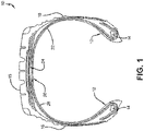
- the tire 10 includes a pair of bead areas 12 and a respective bead core 14 embedded in each bead area.
- a respective sidewall 16 extends radially outward from each bead area 12 to a ground-contacting tread 18.
- the tire 10 is reinforced by a carcass 20 that toroidally extends from one of the bead areas 12 to the other one of the bead areas.
- the carcass 20 includes at least one ply 22 that preferably winds around each bead core 14.
- a belt reinforcement package 24 is disposed between the carcass 20 and the tread 18.
- An innerliner 26 is formed on the inside surface of the carcass.
- the tire 10 is mounted on a wheel 28, as known in the art.
- the method for determining a sidewall toughness index 30 preferably includes conducting different physical tests to evaluate the robustness of the tire sidewall 16. At least two tests are conducted.
- a first test may be a torque tear performance test 32, as shown in Figure 2 .
- the torque tear performance test 32 includes mounting the tire 10 to be tested on a vehicle 34.
- a test fixture 36 is positioned in front of the tire 10 and includes a first plate 38 and a second plate (not shown).
- a preferably sharp object 40 is mounted in the first plate 38, and preferably includes a sharpened end, such as an end that has been machined down to a diameter of 7 mm to 10 mm such as 8.5 mm.
- the vehicle 34 is driven forward into the fixture 36 until the tire 10 passes between the plates.
- the preferably sharp object 40 is positioned laterally so that the machined end makes minimal contact with the tire sidewall 16.
- the vehicle 34 is driven slowly through the test fixture 36 until the tire exits the fixture.
- the object 40 which may be a bolt, is moved or turned in the direction of the tire by one revolution, so that the machined end protrudes further towards the tire sidewall 16, and the vehicle is again driven through the fixture. This process repeats until the tire 10 loses air due to the machined end of the sharp object or bolt 40 tearing the sidewall 16.
- the result of the torque tear performance test 32 is initially indicated as a number of revolutions of the object or bolt 40, which dictates the lateral location of the bolt when the tire 10 loses air.
- the number of revolutions of the bolt 40 determines the performance of the sidewall 16, as a higher number of revolutions of the bolt indicates a higher resistance of the sidewall to torque tearing.
- the method for determining a sidewall toughness index 30 preferably includes conducting at least two different physical tests to evaluate the robustness of the tire sidewall 16.
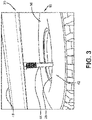
- a second test to evaluate the robustness of the tire sidewall 16 includes a sidewall plunger test 42, which is shown in Figure 3 .
- the sidewall plunger test 42 evaluates a puncture from a preferably sharp object 44 entering the sidewall 16 of the tire 10 from a direction that is normal to the surface of the sidewall.
- the preferably sharp object 44 may be a chisel, and is mounted on an arm or platen 46 of a press that may be hydraulically, pneumatically, or electrically actuated. The load on the chisel 44 at a puncture of the sidewall 16 resulting in loss of air from the tire 10 is recorded.
- the performance of the tire 10 is determined by the load on chisel 44 at a puncture of the sidewall 16 resulting in air loss.
- the result of the sidewall plunger test 42 is initially indicated as the load on the chisel 44 at air loss. Specifically, a higher load on the chisel 44 at puncture of the tire 10 indicates a higher resistance of the sidewall 16 to puncture.
- the result of each test is normalized for each tire type 10, which includes adjusting the values of the results to a common scale 52.
- the result of each test may be converted to a scale ranging from 1 to 5, with 1 being the minimum observable value and 5 being the maximum observable value.
- the number of revolutions from the torque tear performance test 32 is normalized to a torque tear normalized result 48, which in this example is a scale ranging from 1 to 5.
- a higher number of revolutions of the sharp object or bolt 40 and thus a higher torque tear normalized result 48 indicates a higher resistance of the tire sidewall 16 to torque tearing.
- the load on the chisel 44 at tire loss from the sidewall plunger test 42 is normalized to a sidewall plunger normalized result 50, which is in this example is a scale ranging from 1 to 5.
- a higher load on the chisel 44 at puncture of the tire 10 and thus a higher sidewall plunger normalized result 50 indicates a higher resistance of the sidewall 16 to puncture.
- the normalized test results such as the torque tear normalized result 48 and the sidewall plunger normalized result 50, may be combined by summing or weighting to generate a composite score, which is referred to as a sidewall toughness index 54.
- the sidewall toughness index 54 may thus be the sum of the normalized tests being equally weighted, or may be a weighted result of the normalized tests, to provide a composite rating of robustness of the sidewall 16 of the tire 10.
- a value of the sidewall toughness index 54 may range from 2 to 10, which corresponds to summing the result of each individual test, which ranges from 1 to 5.
- a higher value for the sidewall toughness index 54 correlates to a sidewall 16 that is more robust and more resistant to damage. More particularly, as described above, a higher torque tear normalized result 48 indicates a higher resistance of the tire sidewall 16 to torque tearing, and a higher sidewall plunger normalized result 50 indicates a higher resistance of the sidewall to puncture. When both results are added together, a higher sidewall toughness index 54 is achieved, which indicates that the sidewall 16 is more robust and resistant to damage.
- the sidewall toughness index 54 for one type of tire, indicated at Tire 1 may be compared to the sidewall toughness index for another type of tire, indicated at Tire 2.
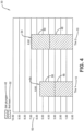
- the torque tear normalized result 48 for Tire 1 is about 3.00 and the sidewall plunger normalized result 50 is about 2.50, yielding a sidewall toughness index 54 of about 5.50.
- the torque tear normalized test result 48 for Tire 2 is about 3.80 and the sidewall plunger normalized result 50 is about 3.12, yielding a sidewall toughness index 54 of about 6.92.
- Tire 2 Based on the higher sidewall toughness index 54, Tire 2 has a more robust sidewall 16, indicating that the sidewall of Tire 2 is more resistant to damage than Tire 1.
- the method for determining a sidewall toughness index 30 enables a respective sidewall toughness index 54 for each one of many types of tires 10 may be compared to one another.
- the sidewall toughness index 54 comprises the torque tear normalized result 48 and the sidewall plunger normalized result 50 for the sidewall 16 of each respective type of tire 10.
- the chart shown in Figure 5 demonstrates a convenient display of individual test performances of each respective type of tire 10 for a normalized comparison.
- the method for determining a sidewall toughness index 30 preferably includes conducting at least two different physical tests to evaluate the robustness of the tire sidewall 16. As shown in Figure 7 , three different tests may be conducted.
- the first test may be the torque tear performance test 32, resulting in the torque tear normalized result 48, which may be in a scale ranging from 1 to 5.
- the second test may be the sidewall plunger test 42, resulting in the sidewall plunger normalized result 50, which may be in a scale ranging from 1 to 5.
- a third test may be a test that measures damage to the sidewall 16 from pinching of the sidewall in the wheel or rim 28, which is known as a rim pinch test 56.
- the tire 10 which preferably is a separate tire from the one used in the torque tear performance test 32 and the sidewall plunger test 42, but is of the same type and construction, is mounted on a wheel 28.
- a wedge object 62 is mounted on an arm or platen 46 of a press that may be hydraulically, pneumatically, or electrically actuated. The wedge 62 is pressed into the crown area of the tire 10, which pinches the sidewall 16 between the wedge and a flange of the rim or wheel 28.
- the load on the wedge 62 is measured, and it is known in the art that internal damage of the tire 10 occurs when there is an abrupt change in the load on the wedge.
- the result of the rim pinch test 56 is initially indicated as the maximum load on the wedge 62 when the abrupt load change occurs.
- a higher value for the result of the rim pinch test 56 indicates a higher resistance of the sidewall 16 to puncture.
- the result of the rim pinch test 56 preferably is normalized to a rim pinch normalized result 60, which is in this example is in a scale ranging from 1 to 5.
- the normalized test results such as the torque tear normalized result 48, the sidewall plunger normalized result 50, and the rim pinch normalized result 60, may be combined by summing or weighting to generate the sidewall toughness index 54.
- a value of the sidewall toughness index 54 may range from 3 to 15, which corresponds to summing the result of each individual test, which ranges from 1 to 5.
- a higher value for the sidewall toughness index 54 correlates to a sidewall 16 that is more robust and more resistant to damage.
- the sidewall toughness index 54 for a first type of tire, indicated at Tire 1 may be compared to the sidewall toughness index for a second type of tire, indicated at Tire 2, and to the sidewall toughness index for a third type of tire, indicated at Tire 3.
- Tire 2 has a higher sidewall toughness index 54, and thus has a more robust sidewall 16 than Tire 1 and Tire 3, indicating that the sidewall of Tire 2 is more resistant to damage than Tire 1 and Tire 3.
- the method for determining a sidewall toughness index 30 enables a respective sidewall toughness index 54 for each one of multiple types of tires 10 may be compared to one another.
- the chart shown in Figure 7 demonstrates a convenient display of individual test performances of each respective type of tire 10 for a normalized comparison.
- tests may be other than those shown and described above without affecting the overall concept or operation of the invention.
- tests may include the torque tear performance test 32, the sidewall plunger test 42, the rim pinch test 56, a sharp object slicing test, and/or materials tests that evaluate a specific material property, such as a Demattia flex test.
- the method for determining a sidewall toughness index 30 is described above employing two different physical tests and three different physical tests, any number or combination of two or more tests may be employed without affecting the overall concept or operation of the invention.
- the method for determining a sidewall toughness index 30 of the present invention provides a method for testing the resistance of tire sidewalls 16 to damage that includes conducting separate physical tests, normalizing the results of each test, and creating a composite sidewall toughness index 54 from the normalized test results.
- the method 30 enables the robustness of tire sidewalls 16 to be determined with increased accuracy and repeatability, regardless of design features that are included on each sidewall.
Landscapes
- Physics & Mathematics (AREA)
- General Physics & Mathematics (AREA)
- Tires In General (AREA)
Abstract
Description
- The invention relates generally to tires. More particularly, the invention relates to the testing of tires, and particularly tire sidewalls. Specifically, the invention is directed to a method for testing the resistance of tire sidewalls to damage that includes conducting separate physical tests, normalizing the results, and creating a composite sidewall toughness index.
- Pneumatic tires have been widely employed. Such tires include a pair of beads that are mounted on a wheel. Each one of pair of sidewalls extends from a respective bead to a groundengaging tread. A carcass, which is made of one or more plies, toroidally extends between the beads to reinforce the sidewalls and the tread. An innerliner is formed on the inside surface of the carcass. The wheel cooperates with the innerliner to define an interior cavity that is inflated with air.
- It has been desirable to test the resistance of the tire sidewalls to damage, and particularly punctures. Sidewall punctures can be a function of a sharp object entering the sidewall at a direction normal to the surface of the sidewall, a torque tear in which the tire rolls past a semi-sharp object, pinching of the sidewall in the wheel or rim, and/or slicing of the tire sidewall by a sharp object. In the prior art, tests have been developed to test the resistance of a sidewall to damage.
- For example, a torque tear test has been used for such testing. The torque tear test includes mounting a tire to be tested on a vehicle. A test fixture is positioned in front of the tire and includes two parallel plates. A sharp object is mounted in one of the plates, and may be a bolt that includes an end which has been machined down to a diameter of about one-third of an inch.
- The vehicle is driven forward into the fixture until the tire passes between the two plates. The parallel plates of the fixture guide the tire and prevent lateral movement. Initially, the sharp object is positioned laterally so that the sharp end makes minimal contact with the tire sidewall. The vehicle is driven slowly through the fixture until the tire exits the plates. After the first pass through the fixture, the sharp object is moved in the direction of the tire, so that the sharp end protrudes further towards the tire sidewall. The vehicle is again driven through the fixture. This process repeats until the tire loses air due to the sharp end tearing the sidewall.
- The amount of movement of the sharp object that leads to air loss of the tire is recorded. The lateral location of the sharp object when the tire loses air determines the performance of the sidewall, in which a greater amount of movement of the sharp object indicates a higher sidewall torque tear resistance. In this manner, the torque tear resistance test provides a measure of the resistance of the tire to sidewall damage. One type of tire may be compared to another using such a method, based upon the amount of movement of the sharp object that lead to air loss.
- While the torque tear performance provides a measure of the resistance of the tire to sidewall damage, and particularly punctures, the test only accounts for a single mode of damage from punctures. It is desirable to improve sidewall testing to account for additional modes of sidewall damage from punctures.
- As a result, there is a need in the art for a method for testing the resistance of a tire sidewall to damage that accounts for multiple modes of sidewall damage from punctures.
- The invention relates to a method in accordance with
claim 1. - Dependent claims refer to preferred embodiments of the invention.
- According to a preferred aspect of the invention, a method for determining a sidewall toughness index for a tire is provided. The method includes the steps of providing a first tire that includes a pair of bead areas, a tread, and a pair of sidewalls, in which each one of the sidewalls extends from a respective one of the bead areas to the tread. A first physical test is conducted on a selected one of the sidewalls of the first tire, and a result of the first physical test is recorded. A second tire of the same type as the first tire is provided. The second tire includes a pair of bead areas, a tread, and a pair of sidewalls, in which each one of the sidewalls extends from a respective one of the bead areas to the tread. A second physical test is conducted on a selected one of the sidewalls of the second tire, and a result of the second physical test is recorded. The result of the first physical test is normalized, and the result of the second physical test is normalized. A sidewall toughness index is generated by combining the normalized result of the first physical test and the normalized result of the second physical test.
- The invention will be described by way of example and with reference to the accompanying drawings, in which:
-
Figure 1 is a cross sectional view of a tire that may be tested in accordance with an exemplary embodiment of the method for determining a sidewall toughness index of the present invention; -
Figure 2 is a schematic perspective view of a first test procedure of an exemplary embodiment of the method for determining a sidewall toughness index of the present invention; -
Figure 3 is a schematic perspective view of a second test procedure of an exemplary embodiment of the method for determining a sidewall toughness index of the present invention; -
Figure 4 is a first graphical representation of a composite sidewall toughness index in accordance with an exemplary embodiment of the method for determining a sidewall toughness index of the present invention; -
Figure 5 is a second graphical representation of a composite sidewall toughness index in accordance with an exemplary embodiment of the method for determining a sidewall toughness index of the present invention; -
Figure 6 is a schematic perspective view of a third test procedure of an exemplary embodiment of the method for determining a sidewall toughness index of the present invention; and -
Figure 7 is a third graphical representation of a composite sidewall toughness index in accordance with an exemplary embodiment of the method for determining a sidewall toughness index of the present invention. - Similar numerals refer to similar parts throughout the drawings.
- "Axial" and "axially" mean lines or directions that are parallel to the axis of rotation of the tire.
- "Circumferential" means lines or directions extending along the perimeter of the surface of the annular tread perpendicular to the axial direction.
- "Radial" and "radially" mean lines or directions that are perpendicular to the axis of rotation of the tire.
- With reference to
Figures 1 through 7 , an exemplary embodiment of themethod 30 for determining a sidewall toughness index of the present invention is explained. The method tests the resistance of a sidewall of atire 10 to damage, as will be described in greater detail below. It is to be understood that the method tests a sidewall of any tire type, including passenger car tires, sport utility vehicle tires, light truck tires, heavy duty truck tires, airplane tires, or tire for off the road vehicles. - Turning to
Figure 1 , thetire 10 includes a pair ofbead areas 12 and arespective bead core 14 embedded in each bead area. Arespective sidewall 16 extends radially outward from eachbead area 12 to a ground-contactingtread 18. Thetire 10 is reinforced by acarcass 20 that toroidally extends from one of thebead areas 12 to the other one of the bead areas. Thecarcass 20 includes at least oneply 22 that preferably winds around eachbead core 14. Abelt reinforcement package 24 is disposed between thecarcass 20 and thetread 18. Aninnerliner 26 is formed on the inside surface of the carcass. As shown inFigure 2 , thetire 10 is mounted on awheel 28, as known in the art. - The method for determining a
sidewall toughness index 30 preferably includes conducting different physical tests to evaluate the robustness of thetire sidewall 16. At least two tests are conducted. By way of example, a first test may be a torquetear performance test 32, as shown inFigure 2 . The torquetear performance test 32 includes mounting thetire 10 to be tested on avehicle 34. Atest fixture 36 is positioned in front of thetire 10 and includes afirst plate 38 and a second plate (not shown). A preferablysharp object 40 is mounted in thefirst plate 38, and preferably includes a sharpened end, such as an end that has been machined down to a diameter of 7 mm to 10 mm such as 8.5 mm. Thevehicle 34 is driven forward into thefixture 36 until thetire 10 passes between the plates. - Initially, the preferably
sharp object 40 is positioned laterally so that the machined end makes minimal contact with thetire sidewall 16. Thevehicle 34 is driven slowly through thetest fixture 36 until the tire exits the fixture. After the first pass of thetire 10 through thefixture 36, theobject 40, which may be a bolt, is moved or turned in the direction of the tire by one revolution, so that the machined end protrudes further towards thetire sidewall 16, and the vehicle is again driven through the fixture. This process repeats until thetire 10 loses air due to the machined end of the sharp object or bolt 40 tearing thesidewall 16. - When the
bolt 40 tears thetire sidewall 16, the number of bolt revolutions that lead to tire air loss is recorded. The result of the torquetear performance test 32 is initially indicated as a number of revolutions of the object orbolt 40, which dictates the lateral location of the bolt when thetire 10 loses air. The number of revolutions of thebolt 40 determines the performance of thesidewall 16, as a higher number of revolutions of the bolt indicates a higher resistance of the sidewall to torque tearing. - As mentioned above, the method for determining a
sidewall toughness index 30 preferably includes conducting at least two different physical tests to evaluate the robustness of thetire sidewall 16. A second test to evaluate the robustness of thetire sidewall 16 includes asidewall plunger test 42, which is shown inFigure 3 . Thesidewall plunger test 42 evaluates a puncture from a preferablysharp object 44 entering thesidewall 16 of thetire 10 from a direction that is normal to the surface of the sidewall. - The
tire 10, which preferably is a separate tire from the one used in the torquetear performance test 32, but is of the same type and construction, is mounted on awheel 28. The preferablysharp object 44 may be a chisel, and is mounted on an arm orplaten 46 of a press that may be hydraulically, pneumatically, or electrically actuated. The load on thechisel 44 at a puncture of thesidewall 16 resulting in loss of air from thetire 10 is recorded. - The performance of the
tire 10 is determined by the load onchisel 44 at a puncture of thesidewall 16 resulting in air loss. The result of thesidewall plunger test 42 is initially indicated as the load on thechisel 44 at air loss. Specifically, a higher load on thechisel 44 at puncture of thetire 10 indicates a higher resistance of thesidewall 16 to puncture. - Turning to
Figure 4 , the result of each test is normalized for eachtire type 10, which includes adjusting the values of the results to acommon scale 52. For example, the result of each test may be converted to a scale ranging from 1 to 5, with 1 being the minimum observable value and 5 being the maximum observable value. - In this manner, the number of revolutions from the torque
tear performance test 32 is normalized to a torque tear normalizedresult 48, which in this example is a scale ranging from 1 to 5. A higher number of revolutions of the sharp object orbolt 40 and thus a higher torque tear normalizedresult 48 indicates a higher resistance of thetire sidewall 16 to torque tearing. Likewise, the load on thechisel 44 at tire loss from thesidewall plunger test 42 is normalized to a sidewall plunger normalizedresult 50, which is in this example is a scale ranging from 1 to 5. A higher load on thechisel 44 at puncture of thetire 10 and thus a higher sidewall plunger normalizedresult 50 indicates a higher resistance of thesidewall 16 to puncture. - To provide a comprehensive evaluation of the robustness of the
sidewall 16 of thetire 10, the normalized test results, such as the torque tear normalizedresult 48 and the sidewall plunger normalizedresult 50, may be combined by summing or weighting to generate a composite score, which is referred to as asidewall toughness index 54. Thesidewall toughness index 54 may thus be the sum of the normalized tests being equally weighted, or may be a weighted result of the normalized tests, to provide a composite rating of robustness of thesidewall 16 of thetire 10. - In this example, a value of the
sidewall toughness index 54 may range from 2 to 10, which corresponds to summing the result of each individual test, which ranges from 1 to 5. A higher value for thesidewall toughness index 54 correlates to asidewall 16 that is more robust and more resistant to damage. More particularly, as described above, a higher torque tear normalizedresult 48 indicates a higher resistance of thetire sidewall 16 to torque tearing, and a higher sidewall plunger normalizedresult 50 indicates a higher resistance of the sidewall to puncture. When both results are added together, a highersidewall toughness index 54 is achieved, which indicates that thesidewall 16 is more robust and resistant to damage. - As shown in
Figure 4 , thesidewall toughness index 54 for one type of tire, indicated atTire 1, may be compared to the sidewall toughness index for another type of tire, indicated atTire 2. In this example, the torque tear normalizedresult 48 forTire 1 is about 3.00 and the sidewall plunger normalizedresult 50 is about 2.50, yielding asidewall toughness index 54 of about 5.50. The torque tear normalizedtest result 48 forTire 2 is about 3.80 and the sidewall plunger normalizedresult 50 is about 3.12, yielding asidewall toughness index 54 of about 6.92. Based on the highersidewall toughness index 54,Tire 2 has a morerobust sidewall 16, indicating that the sidewall ofTire 2 is more resistant to damage thanTire 1. - Turning now to
Figure 5 , the method for determining asidewall toughness index 30 enables a respectivesidewall toughness index 54 for each one of many types oftires 10 may be compared to one another. As described above, thesidewall toughness index 54 comprises the torque tear normalizedresult 48 and the sidewall plunger normalizedresult 50 for thesidewall 16 of each respective type oftire 10. The chart shown inFigure 5 demonstrates a convenient display of individual test performances of each respective type oftire 10 for a normalized comparison. - As mentioned above, the method for determining a
sidewall toughness index 30 preferably includes conducting at least two different physical tests to evaluate the robustness of thetire sidewall 16. As shown inFigure 7 , three different tests may be conducted. The first test may be the torquetear performance test 32, resulting in the torque tear normalizedresult 48, which may be in a scale ranging from 1 to 5. The second test may be thesidewall plunger test 42, resulting in the sidewall plunger normalizedresult 50, which may be in a scale ranging from 1 to 5. - Referring to
Figure 6 , a third test may be a test that measures damage to thesidewall 16 from pinching of the sidewall in the wheel orrim 28, which is known as arim pinch test 56. In therim pinch test 56, thetire 10, which preferably is a separate tire from the one used in the torquetear performance test 32 and thesidewall plunger test 42, but is of the same type and construction, is mounted on awheel 28. Awedge object 62 is mounted on an arm orplaten 46 of a press that may be hydraulically, pneumatically, or electrically actuated. Thewedge 62 is pressed into the crown area of thetire 10, which pinches thesidewall 16 between the wedge and a flange of the rim orwheel 28. The load on thewedge 62 is measured, and it is known in the art that internal damage of thetire 10 occurs when there is an abrupt change in the load on the wedge. The result of therim pinch test 56 is initially indicated as the maximum load on thewedge 62 when the abrupt load change occurs. - Returning to
Figure 7 , a higher value for the result of therim pinch test 56 indicates a higher resistance of thesidewall 16 to puncture. The result of therim pinch test 56 preferably is normalized to a rim pinch normalizedresult 60, which is in this example is in a scale ranging from 1 to 5. - To provide a comprehensive evaluation of the robustness of the
sidewall 16 of thetire 10, the normalized test results, such as the torque tear normalizedresult 48, the sidewall plunger normalizedresult 50, and the rim pinch normalizedresult 60, may be combined by summing or weighting to generate thesidewall toughness index 54. In this example, a value of thesidewall toughness index 54 may range from 3 to 15, which corresponds to summing the result of each individual test, which ranges from 1 to 5. A higher value for thesidewall toughness index 54 correlates to asidewall 16 that is more robust and more resistant to damage. - As shown in
Figure 7 , thesidewall toughness index 54 for a first type of tire, indicated atTire 1, may be compared to the sidewall toughness index for a second type of tire, indicated atTire 2, and to the sidewall toughness index for a third type of tire, indicated atTire 3. In this example,Tire 2 has a highersidewall toughness index 54, and thus has a morerobust sidewall 16 thanTire 1 andTire 3, indicating that the sidewall ofTire 2 is more resistant to damage thanTire 1 andTire 3. - In this manner, the method for determining a
sidewall toughness index 30 enables a respectivesidewall toughness index 54 for each one of multiple types oftires 10 may be compared to one another. The chart shown inFigure 7 demonstrates a convenient display of individual test performances of each respective type oftire 10 for a normalized comparison. - It is to be understood that more than two or three different physical tests may be conducted in the method for determining a
sidewall toughness index 30. The tests may be other than those shown and described above without affecting the overall concept or operation of the invention. For example, tests may include the torquetear performance test 32, thesidewall plunger test 42, therim pinch test 56, a sharp object slicing test, and/or materials tests that evaluate a specific material property, such as a Demattia flex test. In addition, while the method for determining asidewall toughness index 30 is described above employing two different physical tests and three different physical tests, any number or combination of two or more tests may be employed without affecting the overall concept or operation of the invention. - In this manner, the method for determining a
sidewall toughness index 30 of the present invention provides a method for testing the resistance of tire sidewalls 16 to damage that includes conducting separate physical tests, normalizing the results of each test, and creating a compositesidewall toughness index 54 from the normalized test results. Themethod 30 enables the robustness of tire sidewalls 16 to be determined with increased accuracy and repeatability, regardless of design features that are included on each sidewall.
Claims (14)
- A method for determining a sidewall toughness index (54) for a tire (10), the method comprising the steps of:providing a first tire (10) that includes a pair of bead areas (12), a tread (18), and a pair of sidewalls (16), each one of the sidewalls (16) extending from a respective one of the bead areas (12) to the tread (18);conducting a first physical test on a selected one of the sidewalls (16) of the first tire (10);recording a result of the first physical test;providing a second tire (10) of the same type as the first tire, the second tire including a pair of bead areas (12), a tread (18), and a pair of sidewalls (16), each one of the sidewalls (16) extending from a respective one of the bead areas (12) to the tread (18);conducting a second physical test on a selected one of the sidewalls (16) of the second tire (10);recording a result of the second physical test;normalizing the result of the first physical test;normalizing the result of the second physical test; andgenerating a sidewall toughness index (54) by combining the normalized result of the first physical test and the normalized result of the second physical test.
- The method of claim 1, wherein the step of generating a sidewall toughness index (54) by combining the normalized result of the first physical test and the normalized result of the second physical test includes summing the normalized result of the first physical test and the normalized result of the second physical test.
- The method of claim 1 or 2, wherein the step of generating a sidewall toughness index (54) by combining the normalized result of the first physical test and the normalized result of the second physical test includes weighting the normalized result of the first physical test and the normalized result of the second physical test.
- The method of at least one of the previous claims, wherein at least one of the first physical test and the second physical test includes at least one of a torque tear performance test (32), a sidewall plunger test (42), a rim pinch test (56), a sharp object slicing test, and a materials test.
- The method of at least one of the previous claims, wherein the step of conducting the first physical test includes a torque tear performance test (32), and, preferably, wherein the torque tear performance test (32) includes passing the first tire (10) through a fixture (36), the fixture (36) including an object or a bolt (40) with a machined end for engaging the selected one of the tire sidewalls (16).
- The method of claim 5, wherein each time the first tire (10) passes through the fixture (36), the object or bolt (40) is turned in the direction of the first tire (10) by one revolution, until the first tire (10) loses air, and optionally, wherein the result of the first physical test is indicated by a number of revolutions of the object or bolt (40).
- The method of at least one of the previous claims, wherein the step of conducting the second physical test includes a sidewall plunger test (42), and, preferably, wherein the sidewall plunger test (42) evaluates a puncture from a bold or object (44), preferably a sharp bolt or object, entering the selected one of the sidewalls (16) of the second tire (10) from a direction that is normal to the surface of the selected one of the sidewalls (16).
- The method of claim 7, wherein the object (44) is a chisel and wherein the result of the second physical test is indicated by a load on the chisel at a puncture of the selected one of the sidewalls (16) that results in loss of air from the second tire (10).
- The method of at least one of the previous claims, wherein the step of normalizing the results of the first physical test and the second physical test includes converting the result of each test to a scale ranging from 1 to 5, with 1 being a minimum observable value and 5 being a maximum observable value.
- The method of at least one of the previous claims, wherein the step of generating a sidewall toughness index (54) provides a composite rating of robustness of the selected sidewalls (16) of the first and second tires (10), which are of the same type, in a range from 2 to 10, and, optionally, wherein a higher value of the sidewall toughness index (54) indicates that the selected sidewalls (16)are more resistant to damage.
- The method of at least one of the previous claims, wherein the step of generating a sidewall toughness index (54) is a first sidewall toughness index corresponding to the first and second tire type, and the method further comprises the steps of:generating a second sidewall toughness index for a tire type that is different from the first and second tire type; andcomparing the first sidewall toughness index and the second sidewall toughness index.
- The method of at least one of the previous claims, wherein the step of generating a sidewall toughness index (54) is a first sidewall toughness index corresponding to the first and second tire type, and the method further comprises the steps of:generating a plurality of additional sidewall toughness indexes for respective tire types that are different from the first and second tire type; andcomparing the first sidewall toughness index to each of the plurality of additional sidewall toughness indexes.
- The method of at least one of the previous claims, further comprising the steps of:providing a third tire (10) of the same type as the first tire and the second tire, the third tire including a pair of bead areas (14), a tread (18), and a pair of sidewalls (16), each one of the sidewalls (16) extending from a respective one of the bead areas (14) to the tread (18);conducting a third physical test on a selected one of the sidewalls (16) of the third tire (10);recording a result of the third physical test;normalizing the result of the third physical test; andwherein the step of generating a sidewall toughness index includes combining the normalized result of the first physical test, the normalized result of the second physical test, and the normalized result of the third physical test.
- The method of claim 13, wherein at least one of the first physical test, the second physical test, and the third physical test includes at least one of a torque tear performance test (32), a sidewall plunger test (42), a rim pinch test (56), a sharp object slicing test, and a materials test.
Applications Claiming Priority (1)
| Application Number | Priority Date | Filing Date | Title |
|---|---|---|---|
| US17/411,754 US11781945B2 (en) | 2021-08-25 | 2021-08-25 | Tire sidewall toughness index method |
Publications (1)
| Publication Number | Publication Date |
|---|---|
| EP4141405A1 true EP4141405A1 (en) | 2023-03-01 |
Family
ID=83115463
Family Applications (1)
| Application Number | Title | Priority Date | Filing Date |
|---|---|---|---|
| EP22191563.0A Pending EP4141405A1 (en) | 2021-08-25 | 2022-08-22 | Method for determining a sidewall toughness index |
Country Status (2)
| Country | Link |
|---|---|
| US (1) | US11781945B2 (en) |
| EP (1) | EP4141405A1 (en) |
Citations (1)
| Publication number | Priority date | Publication date | Assignee | Title |
|---|---|---|---|---|
| US20120245859A1 (en) * | 2009-11-24 | 2012-09-27 | Compagnie Generale Des Etablissements Michelin | Method of determining sidewall aggression performance parameters |
Family Cites Families (8)
| Publication number | Priority date | Publication date | Assignee | Title |
|---|---|---|---|---|
| US3406566A (en) * | 1964-09-25 | 1968-10-22 | Goodyear Tire & Rubber | Puncture strength tester |
| JPS5568406A (en) | 1978-11-20 | 1980-05-23 | Bridgestone Corp | Air-filled safety tire with effective puncture-proof drivability |
| US6729179B2 (en) * | 2000-04-12 | 2004-05-04 | Pirelli Pneumatici S.P.A. | Method and apparatus for destructive and/or nondestructive testing of one or more tires |
| US20020174019A1 (en) * | 2001-04-06 | 2002-11-21 | Henderson Sheryl Walker | Method for assisting a user in selecting and purchasing tires |
| US7677077B2 (en) | 2006-12-21 | 2010-03-16 | The Goodyear Tire & Rubber Company | Sensor calibration device and method for a tire |
| CN103205031B (en) * | 2012-01-12 | 2017-07-04 | 住友橡胶工业株式会社 | Rubber composition for tire and pneumatic tire |
| JP6012558B2 (en) * | 2013-07-11 | 2016-10-25 | 株式会社ブリヂストン | Tire testing apparatus and tire testing method |
| CN105492222A (en) * | 2013-07-22 | 2016-04-13 | 株式会社普利司通 | pneumatic tire |
-
2021
- 2021-08-25 US US17/411,754 patent/US11781945B2/en active Active
-
2022
- 2022-08-22 EP EP22191563.0A patent/EP4141405A1/en active Pending
Patent Citations (1)
| Publication number | Priority date | Publication date | Assignee | Title |
|---|---|---|---|---|
| US20120245859A1 (en) * | 2009-11-24 | 2012-09-27 | Compagnie Generale Des Etablissements Michelin | Method of determining sidewall aggression performance parameters |
Non-Patent Citations (1)
| Title |
|---|
| HARRIS J.R. ET AL: "Evaluation of Laboratory Tire Tread and Sidewall Strength (Plunger Energy) Test Methods", 31 July 2013 (2013-07-31), XP093005480, Retrieved from the Internet <URL:http://web.archive.org/web/20170303144043/https://www.nhtsa.gov/DOT/NHTSA/NVS/Vehicle%20Research%20&%20Test%20Center%20(VRTC)/ca/Tires/811797.pdf> [retrieved on 20221206] * |
Also Published As
| Publication number | Publication date |
|---|---|
| US11781945B2 (en) | 2023-10-10 |
| US20230067174A1 (en) | 2023-03-02 |
Similar Documents
| Publication | Publication Date | Title |
|---|---|---|
| US10960714B2 (en) | Tire with printed shear sensors | |
| JP5666603B2 (en) | Tires with low permeability carcass reinforcement cords and rubber compounds of various thicknesses | |
| US4351382A (en) | Tire and wheel rim assemblies | |
| JP5719304B2 (en) | Tire with low permeability carcass reinforced cable and reduced thickness rubber compound | |
| US20210370728A1 (en) | Pneumatic tire | |
| US7434607B2 (en) | Pneumatic tire with specified bead apex and sidewall reinforcing rubber layer | |
| US10953710B2 (en) | Tire with printed strain sensors | |
| US10538131B2 (en) | Pneumatic tire | |
| AU2012329419B2 (en) | Heavy load pneumatic radial tire | |
| US11554610B2 (en) | Pneumatic tire | |
| US9956828B2 (en) | Heavy duty pneumatic tire | |
| WO1997001452A1 (en) | Pneumatic radial tyre | |
| US11781945B2 (en) | Tire sidewall toughness index method | |
| US20240109371A1 (en) | Tire | |
| US20240051342A1 (en) | Tire | |
| JP2000127718A (en) | Pneumatic radial tire for heavy loads | |
| EP0967093B1 (en) | Heavy-duty radial tyre | |
| EP1720720A1 (en) | Process for repairing punctured pneumatic tire in tire-rim assembly and repairing system | |
| US3623527A (en) | Pneumatic tire | |
| JP3400005B2 (en) | Pneumatic radial tire | |
| AU2017340843B2 (en) | Bias tire | |
| JP2020060479A (en) | Tire test method | |
| US20240416689A1 (en) | Tire with a set of printed sensors | |
| JP7815927B2 (en) | tire | |
| JP4843157B2 (en) | Formulation evaluation method of rubber composition of tread rubber |
Legal Events
| Date | Code | Title | Description |
|---|---|---|---|
| PUAI | Public reference made under article 153(3) epc to a published international application that has entered the european phase |
Free format text: ORIGINAL CODE: 0009012 |
|
| STAA | Information on the status of an ep patent application or granted ep patent |
Free format text: STATUS: THE APPLICATION HAS BEEN PUBLISHED |
|
| AK | Designated contracting states |
Kind code of ref document: A1 Designated state(s): AL AT BE BG CH CY CZ DE DK EE ES FI FR GB GR HR HU IE IS IT LI LT LU LV MC MK MT NL NO PL PT RO RS SE SI SK SM TR |
|
| STAA | Information on the status of an ep patent application or granted ep patent |
Free format text: STATUS: REQUEST FOR EXAMINATION WAS MADE |
|
| 17P | Request for examination filed |
Effective date: 20230901 |
|
| RBV | Designated contracting states (corrected) |
Designated state(s): AL AT BE BG CH CY CZ DE DK EE ES FI FR GB GR HR HU IE IS IT LI LT LU LV MC MK MT NL NO PL PT RO RS SE SI SK SM TR |
|
| STAA | Information on the status of an ep patent application or granted ep patent |
Free format text: STATUS: EXAMINATION IS IN PROGRESS |
|
| 17Q | First examination report despatched |
Effective date: 20240614 |
|
| 17Q | First examination report despatched |
Effective date: 20240626 |
|
| GRAP | Despatch of communication of intention to grant a patent |
Free format text: ORIGINAL CODE: EPIDOSNIGR1 |
|
| STAA | Information on the status of an ep patent application or granted ep patent |
Free format text: STATUS: GRANT OF PATENT IS INTENDED |
|
| INTG | Intention to grant announced |
Effective date: 20260414 |
|
| RIN1 | Information on inventor provided before grant (corrected) |
Inventor name: DRISCOLL, MICHAEL THOMAS Inventor name: GUBA, STEVEN EMERY Inventor name: GULLATTA, NICHOLAS ANTHONY |
|
| GRAS | Grant fee paid |
Free format text: ORIGINAL CODE: EPIDOSNIGR3 |