EP4141401A1 - Pressure sensor - Google Patents
Pressure sensor Download PDFInfo
- Publication number
- EP4141401A1 EP4141401A1 EP22191927.7A EP22191927A EP4141401A1 EP 4141401 A1 EP4141401 A1 EP 4141401A1 EP 22191927 A EP22191927 A EP 22191927A EP 4141401 A1 EP4141401 A1 EP 4141401A1
- Authority
- EP
- European Patent Office
- Prior art keywords
- concave portion
- pressure sensor
- cover
- housing
- filter
- Prior art date
- Legal status (The legal status is an assumption and is not a legal conclusion. Google has not performed a legal analysis and makes no representation as to the accuracy of the status listed.)
- Granted
Links
Images




Classifications
-
- G—PHYSICS
- G01—MEASURING; TESTING
- G01L—MEASURING FORCE, STRESS, TORQUE, WORK, MECHANICAL POWER, MECHANICAL EFFICIENCY, OR FLUID PRESSURE
- G01L19/00—Details of, or accessories for, apparatus for measuring steady or quasi-steady pressure of a fluent medium insofar as such details or accessories are not special to particular types of pressure gauges
- G01L19/06—Means for preventing overload or deleterious influence of the measured medium on the measuring device or vice versa
- G01L19/0627—Protection against aggressive medium in general
- G01L19/0636—Protection against aggressive medium in general using particle filters
-
- G—PHYSICS
- G01—MEASURING; TESTING
- G01L—MEASURING FORCE, STRESS, TORQUE, WORK, MECHANICAL POWER, MECHANICAL EFFICIENCY, OR FLUID PRESSURE
- G01L19/00—Details of, or accessories for, apparatus for measuring steady or quasi-steady pressure of a fluent medium insofar as such details or accessories are not special to particular types of pressure gauges
- G01L19/14—Housings
-
- G—PHYSICS
- G01—MEASURING; TESTING
- G01L—MEASURING FORCE, STRESS, TORQUE, WORK, MECHANICAL POWER, MECHANICAL EFFICIENCY, OR FLUID PRESSURE
- G01L19/00—Details of, or accessories for, apparatus for measuring steady or quasi-steady pressure of a fluent medium insofar as such details or accessories are not special to particular types of pressure gauges
- G01L19/0007—Fluidic connecting means
- G01L19/003—Fluidic connecting means using a detachable interface or adapter between the process medium and the pressure gauge
-
- G—PHYSICS
- G01—MEASURING; TESTING
- G01L—MEASURING FORCE, STRESS, TORQUE, WORK, MECHANICAL POWER, MECHANICAL EFFICIENCY, OR FLUID PRESSURE
- G01L19/00—Details of, or accessories for, apparatus for measuring steady or quasi-steady pressure of a fluent medium insofar as such details or accessories are not special to particular types of pressure gauges
- G01L19/0061—Electrical connection means
- G01L19/0069—Electrical connection means from the sensor to its support
-
- G—PHYSICS
- G01—MEASURING; TESTING
- G01L—MEASURING FORCE, STRESS, TORQUE, WORK, MECHANICAL POWER, MECHANICAL EFFICIENCY, OR FLUID PRESSURE
- G01L19/00—Details of, or accessories for, apparatus for measuring steady or quasi-steady pressure of a fluent medium insofar as such details or accessories are not special to particular types of pressure gauges
- G01L19/06—Means for preventing overload or deleterious influence of the measured medium on the measuring device or vice versa
- G01L19/0627—Protection against aggressive medium in general
- G01L19/0654—Protection against aggressive medium in general against moisture or humidity
-
- G—PHYSICS
- G01—MEASURING; TESTING
- G01L—MEASURING FORCE, STRESS, TORQUE, WORK, MECHANICAL POWER, MECHANICAL EFFICIENCY, OR FLUID PRESSURE
- G01L19/00—Details of, or accessories for, apparatus for measuring steady or quasi-steady pressure of a fluent medium insofar as such details or accessories are not special to particular types of pressure gauges
- G01L19/14—Housings
- G01L19/142—Multiple part housings
-
- G—PHYSICS
- G01—MEASURING; TESTING
- G01L—MEASURING FORCE, STRESS, TORQUE, WORK, MECHANICAL POWER, MECHANICAL EFFICIENCY, OR FLUID PRESSURE
- G01L19/00—Details of, or accessories for, apparatus for measuring steady or quasi-steady pressure of a fluent medium insofar as such details or accessories are not special to particular types of pressure gauges
- G01L19/14—Housings
- G01L19/142—Multiple part housings
- G01L19/144—Multiple part housings with dismountable parts, e.g. for maintenance purposes or for ensuring sterile conditions
-
- G—PHYSICS
- G01—MEASURING; TESTING
- G01L—MEASURING FORCE, STRESS, TORQUE, WORK, MECHANICAL POWER, MECHANICAL EFFICIENCY, OR FLUID PRESSURE
- G01L9/00—Measuring steady of quasi-steady pressure of fluid or fluent solid material by electric or magnetic pressure-sensitive elements; Transmitting or indicating the displacement of mechanical pressure-sensitive elements, used to measure the steady or quasi-steady pressure of a fluid or fluent solid material, by electric or magnetic means
- G01L9/02—Measuring steady of quasi-steady pressure of fluid or fluent solid material by electric or magnetic pressure-sensitive elements; Transmitting or indicating the displacement of mechanical pressure-sensitive elements, used to measure the steady or quasi-steady pressure of a fluid or fluent solid material, by electric or magnetic means by making use of variations in ohmic resistance, e.g. of potentiometers, electric circuits therefor, e.g. bridges, amplifiers or signal conditioning
- G01L9/04—Measuring steady of quasi-steady pressure of fluid or fluent solid material by electric or magnetic pressure-sensitive elements; Transmitting or indicating the displacement of mechanical pressure-sensitive elements, used to measure the steady or quasi-steady pressure of a fluid or fluent solid material, by electric or magnetic means by making use of variations in ohmic resistance, e.g. of potentiometers, electric circuits therefor, e.g. bridges, amplifiers or signal conditioning of resistance-strain gauges
Definitions
- the present invention relates to a pressure sensor.
- Japanese Unexamined Patent Application Publication No. 2001-296196 discloses a technique related to a pressure sensor in which a filter for preventing the passing through of moisture, dust, and the like while allowing the flow of air is mounted on the atmospheric opening hole.
- a water repellent filter is exemplified as a filter. Since the water repellent filter is exposed to the outside, it may not be possible to prevent clogging due to water or dust that cannot be fully repelled. Further, in this pressure sensor, the shape of the passage related to the opening to the atmosphere is complicated in the interior, and a simpler structure is desired.
- a pressure sensor includes a pressure detector that detects a pressure of a detection target, a housing portion that includes a housing part housing the pressure detector, a concave portion facing the housing part across an inner wall, and a through hole part formed in the inner wall and allowing the housing part and the concave portion to communicate with each other, a filter that covers the through hole part, and a cover that is mounted on the housing portion while covering the concave portion and includes an atmospheric opening part, wherein the concave portion is formed with a bottom surface that is one surface of the inner wall, and two side surfaces that are perpendicular to the bottom surface and are opposed to each other, the cover is formed with an upper plate having a rectangular shape and two side plates having a rectangular shape that are continuous with edges of the upper plate in a vertical direction and are opposed to each other, the upper plate is arranged to face the bottom surface of the concave portion, and the two side plates are arranged between the two side surfaces of the concave portion that are opposed to each other.
- FIG. 1 is a perspective view of a pressure sensor 1 according to a first embodiment.
- FIG. 2 is a perspective view of the pressure sensor 1 before a cover 50 is mounted thereon.
- FIG. 3 is a cross-sectional view of the pressure sensor 1 taken along the line II-II of FIG. 1 .
- the pressure sensor 1 is a gauge pressure type for measuring a pressure of a detection target based on the atmospheric pressure.
- the pressure sensor 1 detects the intake pressure (negative pressure) of an engine serving as a booster, with respect to a brake booster serving as an auxiliary device for reducing the operating force of a brake provided in a vehicle such as an automobile.
- the pressure sensor 1 includes a pressure sensor module 10, a housing portion 20, a terminal portion 30, a filter 40, a cover 50, and a mounting portion 60.
- the pressure sensor module 10 is a pressure detector that detects a pressure of a detection target.
- the pressure sensor module 10 includes a pressure sensor element 11, a wiring board 12, a signal processing circuit 13, and a unit case 14.
- the pressure sensor element 11 is a sensor unit used to detect a pressure of a detection target.
- the pressure range of the pressure sensor element 11 is, for example, 10 to 120 kPa. Note that the pressure sensor element 11 can be appropriately changed depending on the type of detection target, use conditions, or the like.
- the wiring board 12 is, for example, a printed circuit board, on which the pressure sensor element 11, the signal processing circuit 13, and the like are mounted.
- the signal processing circuit 13 is an IC chip that performs predetermined processing and the like on a sensor signal output from the pressure sensor element 11.
- the signal processing circuit 13 is electrically connected to the terminal portion 30.
- the unit case 14 is a resin unit body having a housing space portion 14a for housing the pressure sensor element 11, the wiring board 12, and the signal processing circuit 13.
- the pressure sensor module 10 may include a diaphragm 15, a glass pedestal 16, and a stem 17.
- the diaphragm 15 transmits a pressure change in the detection target as a deformation force to the pressure sensor element 11.
- the glass pedestal 16 in a tubular shape supports the diaphragm 15.
- the stem 17 is an intermediate member that supports the glass pedestal 16 and is interposed for connecting the pressure sensor module 10 and the mounting portion 60.
- the stem 17 includes a hole 17a passing therethrough along the central axis. Air sucked from the outside toward the inside of the engine reaches the diaphragm 15 through the hole 17a from near the mounting portion 60.
- the pressure sensor module 10 is manufactured in advance as one unit. For example, multiple pressure sensor modules 10 having different pressure ranges are prepared in advance, and thus when assembling the pressure sensor 1, the worker can select a pressure sensor module 10 having an appropriate pressure range and start the work quickly.
- the housing portion 20 is formed from a resin material such as PPS resin and serves as a part of the exterior of the pressure sensor 1.
- the housing portion 20 includes a housing body 20a, a connector part 20b, and a connection part 20c, which are continuous with each other as one body.
- the housing body 20a includes a housing part 20d and a concave portion 20s.
- the housing part 20d and the concave portion 20s face each other across an inner wall 20r.
- the inner wall 20r is a flat plate portion perpendicular to the direction in which the mounting portion 60 is connected to the housing portion 20.
- the housing part 20d includes one end to which the mounting portion 60 is connected as an open portion, and houses the pressure sensor module 10.
- the concave portion 20s includes an open portion opposite to where the mounting portion 60 is connected, and in combination with the cover 50, makes the inside a space portion for atmospheric opening.
- the concave portion 20s is formed by a bottom surface 20g, which is one surface of the inner wall 20r, and two side surfaces 20f, which are perpendicular to the bottom surface 20g and are opposed to each other.
- the planar shape of the bottom surface 20g is approximately rectangular.
- the shape of the concave portion 20s has no side surfaces that are perpendicular to the bottom surface 20g and perpendicular to the direction in which the two side surfaces 20f are opposed to each other.
- Each of the side surfaces 20f may be provided with a support part 20j for supporting a part of the back surface of the cover 50 when the cover 50 is mounted on the housing portion 20.
- Each of the support parts 20j faces the cover 50 in the direction in which the cover 50 is mounted, and thus deformation of the cover 50 to the inside of the concave portion 20s is prevented, for example, when the cover 50 receives an impact from the outside.
- the housing body 20a includes two side walls 20h whose surfaces are continuous with the bottom surface 20g of the concave portion 20s and are positioned at the sides of the housing part 20d.
- Each of the side walls 20h includes a projecting part 20i projecting outward.
- Each of the projecting parts 20i engages with an engagement hole 50c provided in the cover 50 when the cover 50 is mounted on the housing portion 20.
- each of the support parts 20j facing the cover 50 and each of the side walls 20h may be recessed to the inside of the housing body 20a by an amount corresponding to the thickness of the cover 50 with respect to the entire outer surface of the housing body 20a.
- the inner wall 20r includes a through hole part 20m that allows the housing part 20d and the concave portion 20s to communicate with each other.
- One opening of the through hole part 20m is positioned at the approximate center of the bottom surface 20g of the concave portion 20s.
- the inner wall 20r includes an open edge 20k for providing the filter 40 to close the opening of the through hole part 20m at the center of the bottom surface 20g of the concave portion 20s.
- the inner wall 20r includes two first groove parts 20n on the bottom surface 20g of the concave portion 20s along the side surfaces 20f of the concave portion 20s with the open edge 20k therebetween, the open edge 20k being the provision position of the filter 40.
- one of the first groove parts 20n is provided in a linear shape in the vicinity of one of the side surfaces 20f along the one side surface 20f.
- the other of the first groove parts 20n is provided in a linear shape in the vicinity of the other of the side surfaces 20f along the other side surface 20f.
- One end of each of the first groove parts 20n is continuous with one of the side walls 20h, and the other end is continuous with the other of the side walls 20h.
- the connector part 20b connects with an external connector of an external wiring member such as a wire harness routed in a vehicle.
- the connector part 20b is continuous to the housing body 20a in a direction perpendicular to the direction in which the mounting portion 60 is connected to the housing portion 20.
- the connector part 20b includes an open part 20e having one end that is open to the outside and exposing a part of the terminal portion 30.
- connection part 20c is formed in a flange shape and connects with the mounting portion 60.
- the connection part 20c is connected to a housing connection part 60b of the mounting portion 60 by being adhered thereto, for example.
- the terminal portion 30 includes multiple terminals that are metal rods for electrically connecting the pressure sensor module 10 and the external wiring of the external connector.
- the terminal portion 30 may include, for example, multiple terminals such as power supply terminals, signal terminals, or ground terminals.
- the filter 40 is a water-repellent filter in a disk sheet shape, which makes it difficult for moisture, dust, and the like to pass therethrough, while allowing air to pass.
- the filter 40 may be fluorine resin formed in a porous state, to which a water repellent treatment is applied.
- the filter 40 is provided on the open edge 20k arranged at the center on the bottom surface 20g of the concave portion 20s of the inner wall 20r.
- the filter 40 may be fixed to the open edge 20k with welding, for example. Thus, one opening of the through hole part 20m facing the concave portion 20s is closed by the filter 40.
- the cover 50 is a member formed from a resin material such as PPS resin and is mounted on the housing portion 20 while covering the concave portion 20s.
- the cover 50 is formed with an upper plate 50a in a rectangular shape and two side plates 50b in a rectangular shape.
- the side plates 50b are continuous from the edges of the upper plate 50a in the vertical direction and thus are opposed to each other.
- the upper plate 50a is arranged to face the bottom surface 20g of the concave portion 20s.
- the side plates 50b are arranged between the two opposed side surfaces 20f of the concave portion 20s.
- each side plate 50b includes the engagement hole 50c that engages with the projecting part 20i formed on the side wall 20h at a part facing the side wall 20h.
- FIG. 4 is a perspective view of the cover 50 as seen from the rear surface side.
- the cover 50 includes an atmospheric opening part for opening a space portion formed between the cover 50 and the concave portion 20s to the atmosphere outside of the pressure sensor 1.
- the atmospheric opening part in the present embodiment includes four cutout parts 50d, each formed in the cover 50 to be continuous from a corner part of the upper plate 50a to a corner part of one of the side plates 50b. Note that in the present embodiment, the total of four cutout parts 50d in one-to-one correspondence to the four corners of the upper plate 50a are formed, but for example, multiple cutout parts 50d corresponding to only some of the four corners of the upper plate 50a may be formed.
- the cover 50 includes multiple ribs 50e on the back surface of the upper plate 50a.
- the back surface of the upper plate 50a corresponds to a surface facing the bottom surface 20g of the concave portion 20s when the cover 50 is mounted on the housing portion 20.
- the ribs 50e are shaped such that when the cover 50 is mounted on the housing portion 20, they each project toward the bottom surface 20g at the outer periphery side of the filter 40 and partially face in a direction in which a corresponding cutout part 50d is formed.
- the tip of each rib 50e may be in contact with the bottom surface 20g when the cover 50 is mounted on the housing portion 20.
- the four ribs 50e are provided in one-to-one correspondence to the four cutout parts 50d.
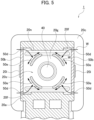
- the four ribs 50e are provided at equal intervals along a circumference of a diameter larger than the outer diameter of the filter 40 to correspond to the respective cutout parts 50d, and are formed of curved wall portions not in contact with each other (see FIG. 5 ).
- a chamfered part 50f may be formed at the open edge 50g of each side plate 50b of the cover 50, which is positioned opposite to the edge of the side plate 50b continuous with the edge of the upper plate 50a. Provision of the chamfered parts 50f facilitates, for example, engagement of the engagement holes 50c with the projecting parts 20i when a worker mounts the cover 50 to the housing portion 20.
- the mounting portion 60 is formed from a resin material such as PPS resin and serves as a part of the exterior of the pressure sensor 1 together with the housing portion 20.
- the mounting portion 60 includes a mounting tube part 60a and a housing connection part 60b, which are continuous with each other as one body.
- the mounting tube part 60a is connected to a mounting hole of a mounted member on which the pressure sensor 1 is mounted.
- the mounting tube part 60a includes on the inner peripheral side a first introduction hole 60c having one end open to the outside. For example, when the pressure sensor 1 is mounted on the mounted member, the first introduction hole 60c is open into a flow path through which air sucked toward the inside of the engine flows.
- the housing connection part 60b is formed in a flange shape and is connected to the connection part 20c of the housing portion 20.
- the housing connection part 60b includes a second introduction hole 60d having a diameter smaller than that of the first introduction hole 60c. One end of the second introduction hole 60d communicates with the first introduction hole 60c. The other end of the second introduction hole 60d is open to the housing part 20d of the housing portion 20.
- the housing connection part 60b tightly holds the pressure sensor module 10 on the housing part 20d side.
- the second introduction hole 60d supports a part of the stem 17 of the pressure sensor module 10 and communicates with the hole 17a of the stem 17.
- one side of the pressure sensor element 11 is open to the atmosphere through the cutout parts 50d, which serves as the atmospheric opening part provided with the cover 50, the concave portion 20s, the through hole part 20m, and the housing part 20d. Then, the pressure sensor element 11 detects the pressure of a detection target reaching the diaphragm 15 through the first introduction hole 60c and the second introduction hole 60d of the mounting portion 60 and the hole 17a of the stem 17.
- the filter 40 is provided according to the position of the through hole part 20m on the passage for the atmospheric opening, the entry of moisture, dust, and the like contained in the atmosphere toward the pressure sensor module 10 is approximately prevented. Further, in the present embodiment, since the filter 40 is not directly exposed to the outside and is arranged inside the space portion surrounded by the cover 50 and the concave portion 20s, moisture, dust, and the like contained in the atmosphere are less likely to reach the filter 40.
- FIG. 5 is a cross-sectional view along the line V-V of FIG. 3 for illustrating the water-blocking action on the filter 40.
- the ribs 50e are arranged between the cutout parts 50d and the filter 40.
- the moisture and the like W entering from the cutout parts 50d hardly adheres to the filter 40. Note that since the ribs 50e adjacent to each other are not in contact with each other, the ribs 50e do not block the atmospheric opening through the filter 40.
- the two first groove parts 20n provided on the inner wall 20r and facing the concave portion 20s act to discharge to the outside the moisture and the like W that has entered the space portion surrounded by the cover 50 and the concave portion 20s. Even if the moisture and the like W enters the space portion surrounded by the cover 50 and the concave portion 20s from the outside through the cutout parts 50d, the moisture and the like W goes to the first groove parts 20n as illustrated by arrows in FIG. 2 . Since both ends of each of the first groove parts 20n are continuous with the side walls 20h, the moisture and the like W flows on the surfaces of the side walls 20h and is subsequently discharged to the outside from the minute space between the side walls 20h and the cover 50.
- the pressure sensor 1 includes a pressure detector (pressure sensor module 10) that detects a pressure of a detection target.
- the pressure sensor 1 includes the housing portion 20 that includes the housing part 20 housing the pressure detector, the concave portion 20s facing the housing part 20d across the inner wall 20r, and the through hole part 20m formed in the inner wall 20r and allowing the housing part 20d and the concave portion 20s to communicate with each other.
- the pressure sensor 1 includes the filter 40 that closes the through hole part 20m, and the cover 50 that is mounted on the housing portion 20 while covering the concave portion 20s and includes the atmospheric opening part.
- the concave portion 20s is formed with the bottom surface 20g, which is one surface of the inner wall 20r, and the two side surfaces 20f that are perpendicular to the bottom surface 20g and are opposed to each other.
- the cover 50 is formed with the upper plate 50a, and the two side plates 50b that are continuous from both edges of the upper plate 50a in the vertical direction and are opposed to each other.
- the upper plate 50a is arranged to face the bottom surface 20g of the concave portion 20s.
- the side plates 50b are arranged between the two opposed side surfaces 20f of the concave portion 20s.
- the filter 40 is provided according to the position of the through hole part 20m serving as the passage for the atmospheric opening, the entry of moisture, dust, and the like contained in the atmosphere toward the pressure sensor module 10 is approximately prevented. Further, in the pressure sensor 1, since the filter 40 is arranged inside the space portion surrounded by the cover 50 and the concave portion 20s, moisture, dust, and the like contained in the atmosphere are less likely to reach the filter 40 than when a filter is directly exposed to the outside. Thus, the pressure sensor 1 is likely to prevent clogging of the filter 40 due to the moisture, dust, and the like contained in the atmosphere.
- the space portion provided for not to directly exposing the filter 40 to the outside is formed with the cover 50 formed only of the upper plate 50a and the two side plates 50b, and the concave portion 20s of the housing portion 20 made to fit to the shape of the cover 50.
- the atmospheric opening part that makes the space portion surrounded by the cover 50 and the concave portion 20s open to the atmosphere is provided in the cover 50.
- the pressure sensor 1 that prevents, with a simple structure, the clogging of the filter 40 provided at a portion maintaining the atmospheric pressure.
- the housing portion 20 may include the two side walls 20h, whose surfaces are positioned at the sides of the housing part 20d and are continuous with the bottom surface 20g of the concave portion 20s, the two side walls 20h including the projecting parts 20i projecting outward.
- the side plates 50b of the cover 50 may have the engagement hole 50c facing one of the two side walls 20h and engaged with one of the projecting parts 20i.
- the cover 50 is mounted on the housing portion 20 with one touch, which is advantageous in terms of improving the ease of assembly.
- the atmospheric opening part may be constituted by the multiple cutout parts 50d, each formed in the cover 50 to be continuous from a corner part of the upper plate 50a to a corner part of one of the side plates 50b.
- the space portion surrounded by the cover 50 and the concave portion 20s is open to the atmosphere through the end parts of the space portion, and thus even if moisture, dust, and the like enters the space portion, it is possible to make it difficult for the moisture, dust, and the like to reach the filter 40. Consequently, it is possible to prevent the clogging of the filter 40 with more ease.
- the filter 40 may be provided at the center of the bottom surface 20g of the concave portion 20s of the inner wall 20r.
- the inner wall 20r may include the two first groove parts 20n, each having one end continuous with one side wall 20h and the other end continuous with the other side wall 20h, on the bottom surface 20g of the concave portion 20s along the side surfaces 20f of the concave portion 20s with the filter 40 provided therebetween.
- the cover 50 may include the ribs 50e on the surface facing the bottom surface 20g of the concave portion 20s.
- the ribs 50e each project toward the bottom surface 20g at the outer periphery side of the filter 40 and partially face in a direction in which a corresponding cutout part 50d is formed.
- the cutout parts 50d are exemplified as the atmospheric opening part included in the cover 50.
- the shape of the cover is further simplified.
- FIG. 6 is a perspective view of a pressure sensor 2 according to the second embodiment.
- FIG. 7 is a perspective view of the pressure sensor 2 before a cover 70 is mounted thereon.
- FIG. 8 is a perspective view of the cover 70 as seen from the rear surface side.
- FIG. 6 corresponds to FIG. 1 of the first embodiment.
- FIG. 7 corresponds to FIG. 2 of the first embodiment.
- FIG. 8 corresponds to FIG. 4 of the first embodiment.
- components having the same configuration as the pressure sensor 1 according to the first embodiment are denoted by the same reference numerals, and the description thereof will be omitted below.
- the cover 70 includes an upper plate 70a, two side plates 70b, two engaging holes 70c, and two chamfered parts 70f. However, the cover 70 does not include the cutout parts 50d and the ribs 50e provided on the cover 50.
- the atmospheric opening part in the present embodiment is constituted by open edges 70g of the side plates 70b, each of the open edges 70g is positioned opposite to the edge of the side plate 70b continuous with one of the edges of the upper plate 70a.
- the height of each of the side plates 70b is shorter than the height of each of the side plates 50b in the first embodiment. Consequently, as illustrated in FIG. 6 , when the cover 70 is mounted on the housing portion 20, a gap G is formed between each of the open edges 70g and the connection portion 20c.
- the inner wall 20r and the side walls 20h include two second groove parts 20p instead of the two first groove parts 20n in the first embodiment.
- the two second groove parts 20p are formed to be continuous from the bottom surface 20g of the concave portion 20s to the surfaces of the side walls 20h along the side surfaces 20f of the concave portion 20s with the filter 40 provided therebetween.
- a space portion surrounded by the cover 70 and the concave portion 20s is open to the atmosphere through the gap G.
- a part of the second groove part 20p continuous from the gap G to the bottom surface 20g exists in a region between the each of the side walls 20h and each of the side plates 70b of the cover 70.
- the second groove parts 20p it is possible for the second groove parts 20p to act as a flow path for opening to the atmosphere in addition to the drainage action in a similar manner in the first embodiment.
- the cover 70 since the open edges 70g of the cover 70 serves as the atmospheric opening part, it is practically difficult for moisture and the like from the outside to directly adhere to the filter 40. Thus, the cover 70 need not be provided with parts like the ribs 50e of the cover 50 in the first embodiment.
- the atmospheric opening part may be constituted by the open edges 70g of the side plates 70b, each of the open edges 70g is positioned opposite to the side continuous with one of the edges of the upper plate 70a.
- the inner wall 20r and the side walls 20h may be continuous on the bottom surface 20g of the concave portion 20s and the surfaces of the side walls 20h and may include the two second groove parts 20p along the side surfaces 20f of the concave portion 20s with the filter 40 provided therebetween.
- the second groove parts 20p act as a flow path for promoting the opening to the atmosphere while acting to discharge water and the like W to the outside as in the first embodiment.
- the shape of the cover 70 is simplified, it is possible to prevent the clogging of the filter 40.
Landscapes
- Physics & Mathematics (AREA)
- General Physics & Mathematics (AREA)
- Chemical & Material Sciences (AREA)
- Analytical Chemistry (AREA)
- Measuring Fluid Pressure (AREA)
Abstract
Description
- The present invention relates to a pressure sensor.
- In conventional gauge pressure type pressure sensors, which measure based on atmospheric pressure, one end of the pressure detector is open to the atmosphere. However, if the pressure detector is simply open to the atmosphere, there is a concern that a failure due to moisture or dust entering the sensor through the atmospheric opening hole or a decrease in detection accuracy due to clogging of the atmospheric opening hole may occur. Thus,
Japanese Unexamined Patent Application Publication No. 2001-296196 - In the pressure sensor disclosed in
Japanese Unexamined Patent Application Publication No. 2001-296196 - It is an object of the present invention to provide a pressure sensor that prevents the clogging of a filter provided at a portion maintaining the atmospheric pressure, with a simple structure.
- A pressure sensor according to an aspect of the present invention includes a pressure detector that detects a pressure of a detection target, a housing portion that includes a housing part housing the pressure detector, a concave portion facing the housing part across an inner wall, and a through hole part formed in the inner wall and allowing the housing part and the concave portion to communicate with each other, a filter that covers the through hole part, and a cover that is mounted on the housing portion while covering the concave portion and includes an atmospheric opening part, wherein the concave portion is formed with a bottom surface that is one surface of the inner wall, and two side surfaces that are perpendicular to the bottom surface and are opposed to each other, the cover is formed with an upper plate having a rectangular shape and two side plates having a rectangular shape that are continuous with edges of the upper plate in a vertical direction and are opposed to each other, the upper plate is arranged to face the bottom surface of the concave portion, and the two side plates are arranged between the two side surfaces of the concave portion that are opposed to each other.
-
-
FIG. 1 is a perspective view of a pressure sensor according to a first embodiment. -
FIG. 2 is a perspective view of the pressure sensor before a cover is mounted thereon in the first embodiment. -
FIG. 3 is a cross-sectional view of the pressure sensor according to the first embodiment. -
FIG. 4 is a perspective view of the cover as seen from the rear surface side in the first embodiment. -
FIG. 5 is a cross-sectional view for explaining a water-blocking action on a filter in the first embodiment. -
FIG. 6 is a perspective view of a pressure sensor according to a second embodiment. -
FIG. 7 is a perspective view of the pressure sensor before a cover is mounted thereon in the second embodiment. -
FIG. 8 is a perspective view of the cover as seen from the rear surface side in the second embodiment. - Various embodiments will be described hereinafter with reference to the accompanying drawings.
- The pressure sensor according to each embodiment will be described in detail below with reference to the drawings. Note that dimension ratios in the drawings are exaggerated for convenience of explanation and are sometimes different from actual ratios.
-
FIG. 1 is a perspective view of apressure sensor 1 according to a first embodiment.FIG. 2 is a perspective view of thepressure sensor 1 before acover 50 is mounted thereon.FIG. 3 is a cross-sectional view of thepressure sensor 1 taken along the line II-II ofFIG. 1 . - The
pressure sensor 1 is a gauge pressure type for measuring a pressure of a detection target based on the atmospheric pressure. In the present embodiment, as an example, thepressure sensor 1 detects the intake pressure (negative pressure) of an engine serving as a booster, with respect to a brake booster serving as an auxiliary device for reducing the operating force of a brake provided in a vehicle such as an automobile. Thepressure sensor 1 includes apressure sensor module 10, ahousing portion 20, aterminal portion 30, afilter 40, acover 50, and amounting portion 60. - The
pressure sensor module 10 is a pressure detector that detects a pressure of a detection target. Thepressure sensor module 10 includes apressure sensor element 11, awiring board 12, asignal processing circuit 13, and aunit case 14. Thepressure sensor element 11 is a sensor unit used to detect a pressure of a detection target. The pressure range of thepressure sensor element 11 is, for example, 10 to 120 kPa. Note that thepressure sensor element 11 can be appropriately changed depending on the type of detection target, use conditions, or the like. Thewiring board 12 is, for example, a printed circuit board, on which thepressure sensor element 11, thesignal processing circuit 13, and the like are mounted. Thesignal processing circuit 13 is an IC chip that performs predetermined processing and the like on a sensor signal output from thepressure sensor element 11. Thesignal processing circuit 13 is electrically connected to theterminal portion 30. Theunit case 14 is a resin unit body having ahousing space portion 14a for housing thepressure sensor element 11, thewiring board 12, and thesignal processing circuit 13. - The
pressure sensor module 10 may include adiaphragm 15, aglass pedestal 16, and astem 17. Thediaphragm 15 transmits a pressure change in the detection target as a deformation force to thepressure sensor element 11. Theglass pedestal 16 in a tubular shape supports thediaphragm 15. Thestem 17 is an intermediate member that supports theglass pedestal 16 and is interposed for connecting thepressure sensor module 10 and themounting portion 60. Thestem 17 includes ahole 17a passing therethrough along the central axis. Air sucked from the outside toward the inside of the engine reaches thediaphragm 15 through thehole 17a from near themounting portion 60. - Further, the
pressure sensor module 10 is manufactured in advance as one unit. For example, multiplepressure sensor modules 10 having different pressure ranges are prepared in advance, and thus when assembling thepressure sensor 1, the worker can select apressure sensor module 10 having an appropriate pressure range and start the work quickly. - The
housing portion 20 is formed from a resin material such as PPS resin and serves as a part of the exterior of thepressure sensor 1. Thehousing portion 20 includes ahousing body 20a, aconnector part 20b, and aconnection part 20c, which are continuous with each other as one body. - The
housing body 20a includes ahousing part 20d and aconcave portion 20s. Thehousing part 20d and theconcave portion 20s face each other across aninner wall 20r. Theinner wall 20r is a flat plate portion perpendicular to the direction in which themounting portion 60 is connected to thehousing portion 20. - The
housing part 20d includes one end to which themounting portion 60 is connected as an open portion, and houses thepressure sensor module 10. - The
concave portion 20s includes an open portion opposite to where themounting portion 60 is connected, and in combination with thecover 50, makes the inside a space portion for atmospheric opening. Specifically, theconcave portion 20s is formed by abottom surface 20g, which is one surface of theinner wall 20r, and twoside surfaces 20f, which are perpendicular to thebottom surface 20g and are opposed to each other. The planar shape of thebottom surface 20g is approximately rectangular. Here, the shape of theconcave portion 20s has no side surfaces that are perpendicular to thebottom surface 20g and perpendicular to the direction in which the twoside surfaces 20f are opposed to each other. - Each of the
side surfaces 20f may be provided with asupport part 20j for supporting a part of the back surface of thecover 50 when thecover 50 is mounted on thehousing portion 20. Each of thesupport parts 20j faces thecover 50 in the direction in which thecover 50 is mounted, and thus deformation of thecover 50 to the inside of theconcave portion 20s is prevented, for example, when thecover 50 receives an impact from the outside. - The
housing body 20a includes twoside walls 20h whose surfaces are continuous with thebottom surface 20g of theconcave portion 20s and are positioned at the sides of thehousing part 20d. Each of theside walls 20h includes a projectingpart 20i projecting outward. Each of the projectingparts 20i engages with anengagement hole 50c provided in thecover 50 when thecover 50 is mounted on thehousing portion 20. - The end part of each of the
support parts 20j facing thecover 50 and each of theside walls 20h may be recessed to the inside of thehousing body 20a by an amount corresponding to the thickness of thecover 50 with respect to the entire outer surface of thehousing body 20a. With the above-described shape, when thecover 50 is mounted on thehousing portion 20, the height positions of thehousing body 20a and thecover 50 are matched to each other, and the entire outer surface of thehousing portion 20 becomes uniform, which is advantageous in terms of ease of handling due to the simple shape or in terms of appearance. - The
inner wall 20r includes a throughhole part 20m that allows thehousing part 20d and theconcave portion 20s to communicate with each other. One opening of the throughhole part 20m is positioned at the approximate center of thebottom surface 20g of theconcave portion 20s. Theinner wall 20r includes anopen edge 20k for providing thefilter 40 to close the opening of the throughhole part 20m at the center of thebottom surface 20g of theconcave portion 20s. - The
inner wall 20r includes twofirst groove parts 20n on thebottom surface 20g of theconcave portion 20s along the side surfaces 20f of theconcave portion 20s with theopen edge 20k therebetween, theopen edge 20k being the provision position of thefilter 40. Specifically, as illustrated inFIG. 2 , one of thefirst groove parts 20n is provided in a linear shape in the vicinity of one of theside surfaces 20f along the oneside surface 20f. In a similar manner, the other of thefirst groove parts 20n is provided in a linear shape in the vicinity of the other of theside surfaces 20f along theother side surface 20f. One end of each of thefirst groove parts 20n is continuous with one of theside walls 20h, and the other end is continuous with the other of theside walls 20h. - The
connector part 20b connects with an external connector of an external wiring member such as a wire harness routed in a vehicle. In the present embodiment, theconnector part 20b is continuous to thehousing body 20a in a direction perpendicular to the direction in which the mountingportion 60 is connected to thehousing portion 20. Theconnector part 20b includes anopen part 20e having one end that is open to the outside and exposing a part of theterminal portion 30. - The
connection part 20c is formed in a flange shape and connects with the mountingportion 60. Theconnection part 20c is connected to ahousing connection part 60b of the mountingportion 60 by being adhered thereto, for example. - The
terminal portion 30 includes multiple terminals that are metal rods for electrically connecting thepressure sensor module 10 and the external wiring of the external connector. Theterminal portion 30 may include, for example, multiple terminals such as power supply terminals, signal terminals, or ground terminals. - The
filter 40 is a water-repellent filter in a disk sheet shape, which makes it difficult for moisture, dust, and the like to pass therethrough, while allowing air to pass. For example, thefilter 40 may be fluorine resin formed in a porous state, to which a water repellent treatment is applied. Thefilter 40 is provided on theopen edge 20k arranged at the center on thebottom surface 20g of theconcave portion 20s of theinner wall 20r. Here, thefilter 40 may be fixed to theopen edge 20k with welding, for example. Thus, one opening of the throughhole part 20m facing theconcave portion 20s is closed by thefilter 40. - The
cover 50 is a member formed from a resin material such as PPS resin and is mounted on thehousing portion 20 while covering theconcave portion 20s. Thecover 50 is formed with anupper plate 50a in a rectangular shape and twoside plates 50b in a rectangular shape. Theside plates 50b are continuous from the edges of theupper plate 50a in the vertical direction and thus are opposed to each other. When thecover 50 is mounted on thehousing portion 20, theupper plate 50a is arranged to face thebottom surface 20g of theconcave portion 20s. In contrast, theside plates 50b are arranged between the two opposed side surfaces 20f of theconcave portion 20s. When thecover 50 is mounted on thehousing portion 20, a part of oneside plate 50b faces oneside wall 20h, and a part of theother side plate 50b faces theother side wall 20h. Eachside plate 50b includes theengagement hole 50c that engages with the projectingpart 20i formed on theside wall 20h at a part facing theside wall 20h. -
FIG. 4 is a perspective view of thecover 50 as seen from the rear surface side. Thecover 50 includes an atmospheric opening part for opening a space portion formed between thecover 50 and theconcave portion 20s to the atmosphere outside of thepressure sensor 1. The atmospheric opening part in the present embodiment includes fourcutout parts 50d, each formed in thecover 50 to be continuous from a corner part of theupper plate 50a to a corner part of one of theside plates 50b. Note that in the present embodiment, the total of fourcutout parts 50d in one-to-one correspondence to the four corners of theupper plate 50a are formed, but for example,multiple cutout parts 50d corresponding to only some of the four corners of theupper plate 50a may be formed. - The
cover 50 includesmultiple ribs 50e on the back surface of theupper plate 50a. Here, the back surface of theupper plate 50a corresponds to a surface facing thebottom surface 20g of theconcave portion 20s when thecover 50 is mounted on thehousing portion 20. Theribs 50e are shaped such that when thecover 50 is mounted on thehousing portion 20, they each project toward thebottom surface 20g at the outer periphery side of thefilter 40 and partially face in a direction in which acorresponding cutout part 50d is formed. The tip of eachrib 50e may be in contact with thebottom surface 20g when thecover 50 is mounted on thehousing portion 20. In the present embodiment, the fourribs 50e are provided in one-to-one correspondence to the fourcutout parts 50d. The fourribs 50e are provided at equal intervals along a circumference of a diameter larger than the outer diameter of thefilter 40 to correspond to therespective cutout parts 50d, and are formed of curved wall portions not in contact with each other (seeFIG. 5 ). - Note that as illustrated in
FIG. 4 , achamfered part 50f may be formed at theopen edge 50g of eachside plate 50b of thecover 50, which is positioned opposite to the edge of theside plate 50b continuous with the edge of theupper plate 50a. Provision of the chamferedparts 50f facilitates, for example, engagement of theengagement holes 50c with the projectingparts 20i when a worker mounts thecover 50 to thehousing portion 20. - The mounting
portion 60 is formed from a resin material such as PPS resin and serves as a part of the exterior of thepressure sensor 1 together with thehousing portion 20. The mountingportion 60 includes a mountingtube part 60a and ahousing connection part 60b, which are continuous with each other as one body. - The mounting
tube part 60a is connected to a mounting hole of a mounted member on which thepressure sensor 1 is mounted. The mountingtube part 60a includes on the inner peripheral side afirst introduction hole 60c having one end open to the outside. For example, when thepressure sensor 1 is mounted on the mounted member, thefirst introduction hole 60c is open into a flow path through which air sucked toward the inside of the engine flows. - The
housing connection part 60b is formed in a flange shape and is connected to theconnection part 20c of thehousing portion 20. Thehousing connection part 60b includes asecond introduction hole 60d having a diameter smaller than that of thefirst introduction hole 60c. One end of thesecond introduction hole 60d communicates with thefirst introduction hole 60c. The other end of thesecond introduction hole 60d is open to thehousing part 20d of thehousing portion 20. Thehousing connection part 60b tightly holds thepressure sensor module 10 on thehousing part 20d side. Thesecond introduction hole 60d supports a part of thestem 17 of thepressure sensor module 10 and communicates with thehole 17a of thestem 17. - Next, the operation of the
pressure sensor 1 will be described. - First, in the
pressure sensor 1, one side of thepressure sensor element 11 is open to the atmosphere through thecutout parts 50d, which serves as the atmospheric opening part provided with thecover 50, theconcave portion 20s, the throughhole part 20m, and thehousing part 20d. Then, thepressure sensor element 11 detects the pressure of a detection target reaching thediaphragm 15 through thefirst introduction hole 60c and thesecond introduction hole 60d of the mountingportion 60 and thehole 17a of thestem 17. - Here, in the present embodiment, since the
filter 40 is provided according to the position of the throughhole part 20m on the passage for the atmospheric opening, the entry of moisture, dust, and the like contained in the atmosphere toward thepressure sensor module 10 is approximately prevented. Further, in the present embodiment, since thefilter 40 is not directly exposed to the outside and is arranged inside the space portion surrounded by thecover 50 and theconcave portion 20s, moisture, dust, and the like contained in the atmosphere are less likely to reach thefilter 40. - In the present embodiment, the
multiple ribs 50e provided on thecover 50 act to prevent thefilter 40 from being wet.FIG. 5 is a cross-sectional view along the line V-V ofFIG. 3 for illustrating the water-blocking action on thefilter 40. In the space portion surrounded by thecover 50 and theconcave portion 20s, theribs 50e are arranged between thecutout parts 50d and thefilter 40. Thus, even if moisture and the like W enters the space portion surrounded by thecover 50 and theconcave portion 20s from the outside through thecutout parts 50d, as indicated by arrows inFIG. 5 , the moisture and the like W is blocked by thecutout parts 50d and cannot directly go to thefilter 40. That is, the moisture and the like W entering from thecutout parts 50d hardly adheres to thefilter 40. Note that since theribs 50e adjacent to each other are not in contact with each other, theribs 50e do not block the atmospheric opening through thefilter 40. - Further, in the present embodiment, the two
first groove parts 20n provided on theinner wall 20r and facing theconcave portion 20s act to discharge to the outside the moisture and the like W that has entered the space portion surrounded by thecover 50 and theconcave portion 20s. Even if the moisture and the like W enters the space portion surrounded by thecover 50 and theconcave portion 20s from the outside through thecutout parts 50d, the moisture and the like W goes to thefirst groove parts 20n as illustrated by arrows inFIG. 2 . Since both ends of each of thefirst groove parts 20n are continuous with theside walls 20h, the moisture and the like W flows on the surfaces of theside walls 20h and is subsequently discharged to the outside from the minute space between theside walls 20h and thecover 50. - Next, the effect of the
pressure sensor 1 will be described. - The
pressure sensor 1 according to the present embodiment includes a pressure detector (pressure sensor module 10) that detects a pressure of a detection target. Thepressure sensor 1 includes thehousing portion 20 that includes thehousing part 20 housing the pressure detector, theconcave portion 20s facing thehousing part 20d across theinner wall 20r, and the throughhole part 20m formed in theinner wall 20r and allowing thehousing part 20d and theconcave portion 20s to communicate with each other. Thepressure sensor 1 includes thefilter 40 that closes the throughhole part 20m, and thecover 50 that is mounted on thehousing portion 20 while covering theconcave portion 20s and includes the atmospheric opening part. Theconcave portion 20s is formed with thebottom surface 20g, which is one surface of theinner wall 20r, and the twoside surfaces 20f that are perpendicular to thebottom surface 20g and are opposed to each other. Thecover 50 is formed with theupper plate 50a, and the twoside plates 50b that are continuous from both edges of theupper plate 50a in the vertical direction and are opposed to each other. Theupper plate 50a is arranged to face thebottom surface 20g of theconcave portion 20s. Theside plates 50b are arranged between the two opposed side surfaces 20f of theconcave portion 20s. - First, in the
pressure sensor 1, since thefilter 40 is provided according to the position of the throughhole part 20m serving as the passage for the atmospheric opening, the entry of moisture, dust, and the like contained in the atmosphere toward thepressure sensor module 10 is approximately prevented. Further, in thepressure sensor 1, since thefilter 40 is arranged inside the space portion surrounded by thecover 50 and theconcave portion 20s, moisture, dust, and the like contained in the atmosphere are less likely to reach thefilter 40 than when a filter is directly exposed to the outside. Thus, thepressure sensor 1 is likely to prevent clogging of thefilter 40 due to the moisture, dust, and the like contained in the atmosphere. - In the
pressure sensor 1, the space portion provided for not to directly exposing thefilter 40 to the outside is formed with thecover 50 formed only of theupper plate 50a and the twoside plates 50b, and theconcave portion 20s of thehousing portion 20 made to fit to the shape of thecover 50. The atmospheric opening part that makes the space portion surrounded by thecover 50 and theconcave portion 20s open to the atmosphere is provided in thecover 50. This enables the structure of thepressure sensor 1 as a whole to be simplified because it is not necessary to separately configure a flow path, a hole, and the like functioning as the atmospheric opening part in thehousing portion 20 while avoiding the complicated shape of thecover 50. - As described above, according to the present embodiment, it is possible to provide the
pressure sensor 1 that prevents, with a simple structure, the clogging of thefilter 40 provided at a portion maintaining the atmospheric pressure. - In the
pressure sensor 1 according to the present embodiment, thehousing portion 20 may include the twoside walls 20h, whose surfaces are positioned at the sides of thehousing part 20d and are continuous with thebottom surface 20g of theconcave portion 20s, the twoside walls 20h including the projectingparts 20i projecting outward. Apart of each of theside plates 50b of thecover 50 may have theengagement hole 50c facing one of the twoside walls 20h and engaged with one of the projectingparts 20i. - In the
pressure sensor 1, for example, when a worker assembles thepressure sensor 1, it is possible for thecover 50 to be mounted on thehousing portion 20 with one touch, which is advantageous in terms of improving the ease of assembly. - In the
pressure sensor 1 according to the present embodiment, the atmospheric opening part may be constituted by themultiple cutout parts 50d, each formed in thecover 50 to be continuous from a corner part of theupper plate 50a to a corner part of one of theside plates 50b. - In the
pressure sensor 1, the space portion surrounded by thecover 50 and theconcave portion 20s is open to the atmosphere through the end parts of the space portion, and thus even if moisture, dust, and the like enters the space portion, it is possible to make it difficult for the moisture, dust, and the like to reach thefilter 40. Consequently, it is possible to prevent the clogging of thefilter 40 with more ease. - In the
pressure sensor 1 according to the present embodiment, thefilter 40 may be provided at the center of thebottom surface 20g of theconcave portion 20s of theinner wall 20r. Theinner wall 20r may include the twofirst groove parts 20n, each having one end continuous with oneside wall 20h and the other end continuous with theother side wall 20h, on thebottom surface 20g of theconcave portion 20s along the side surfaces 20f of theconcave portion 20s with thefilter 40 provided therebetween. - In the
pressure sensor 1, as described above as a drainage action, even if moisture and the like W enters the space portion surrounded by thecover 50 and theconcave portion 20s through thecutout parts 50d, it is possible to discharge with ease the moisture and the like W to the outside through thefirst groove parts 20n. Consequently, it is possible to prevent the clogging of thefilter 40 with more ease. - In the
pressure sensor 1 according to the present embodiment, thecover 50 may include theribs 50e on the surface facing thebottom surface 20g of theconcave portion 20s. Theribs 50e each project toward thebottom surface 20g at the outer periphery side of thefilter 40 and partially face in a direction in which acorresponding cutout part 50d is formed. - In the
pressure sensor 1, as described above as a water-blocking action, even if moisture and the like W enters the space portion surrounded by thecover 50 and theconcave portion 20s through thecutout parts 50d, it is possible to make it difficult for the moisture and the like W to adhere to thefilter 40. Consequently, it is possible to prevent the clogging of thefilter 40 with more ease. - In the first embodiment, the
cutout parts 50d are exemplified as the atmospheric opening part included in thecover 50. In contrast, in the present embodiment, an example in which the shape of the cover is further simplified will be described. -
FIG. 6 is a perspective view of apressure sensor 2 according to the second embodiment.FIG. 7 is a perspective view of thepressure sensor 2 before acover 70 is mounted thereon.FIG. 8 is a perspective view of thecover 70 as seen from the rear surface side. Here,FIG. 6 corresponds toFIG. 1 of the first embodiment.FIG. 7 corresponds toFIG. 2 of the first embodiment.FIG. 8 corresponds toFIG. 4 of the first embodiment. Regarding thepressure sensor 2, components having the same configuration as thepressure sensor 1 according to the first embodiment are denoted by the same reference numerals, and the description thereof will be omitted below. - Similar to the
cover 50 in the first embodiment, thecover 70 includes anupper plate 70a, twoside plates 70b, two engagingholes 70c, and two chamferedparts 70f. However, thecover 70 does not include thecutout parts 50d and theribs 50e provided on thecover 50. - As an alternative configuration in which the
cover 70 does not include thecutout parts 50d and theribs 50e, first, the atmospheric opening part in the present embodiment is constituted byopen edges 70g of theside plates 70b, each of theopen edges 70g is positioned opposite to the edge of theside plate 70b continuous with one of the edges of theupper plate 70a. Here, the height of each of theside plates 70b is shorter than the height of each of theside plates 50b in the first embodiment. Consequently, as illustrated inFIG. 6 , when thecover 70 is mounted on thehousing portion 20, a gap G is formed between each of theopen edges 70g and theconnection portion 20c. - Meanwhile, in the
housing portion 20 in the present embodiment, theinner wall 20r and theside walls 20h include twosecond groove parts 20p instead of the twofirst groove parts 20n in the first embodiment. The twosecond groove parts 20p are formed to be continuous from thebottom surface 20g of theconcave portion 20s to the surfaces of theside walls 20h along the side surfaces 20f of theconcave portion 20s with thefilter 40 provided therebetween. - In the
pressure sensor 2 having such a configuration, a space portion surrounded by thecover 70 and theconcave portion 20s is open to the atmosphere through the gap G. Here, a part of thesecond groove part 20p continuous from the gap G to thebottom surface 20g exists in a region between the each of theside walls 20h and each of theside plates 70b of thecover 70. Thus, it is possible for thesecond groove parts 20p to act as a flow path for opening to the atmosphere in addition to the drainage action in a similar manner in the first embodiment. - Here, since the
open edges 70g of thecover 70 serves as the atmospheric opening part, it is practically difficult for moisture and the like from the outside to directly adhere to thefilter 40. Thus, thecover 70 need not be provided with parts like theribs 50e of thecover 50 in the first embodiment. - As described above, in the
pressure sensor 2 according to the present embodiment, first, the atmospheric opening part may be constituted by theopen edges 70g of theside plates 70b, each of theopen edges 70g is positioned opposite to the side continuous with one of the edges of theupper plate 70a. - In the
pressure sensor 2, it is possible to make the shape of thecover 70 simpler than that of thecover 50 in the first embodiment. - In the
pressure sensor 2 according to the present embodiment, theinner wall 20r and theside walls 20h may be continuous on thebottom surface 20g of theconcave portion 20s and the surfaces of theside walls 20h and may include the twosecond groove parts 20p along the side surfaces 20f of theconcave portion 20s with thefilter 40 provided therebetween. - In the
pressure sensor 2, thesecond groove parts 20p act as a flow path for promoting the opening to the atmosphere while acting to discharge water and the like W to the outside as in the first embodiment. Thus, even if the shape of thecover 70 is simplified, it is possible to prevent the clogging of thefilter 40. - Although the present invention has been described above by reference to the embodiment, the present invention is not limited to those and the configuration of parts can be replaced with any configuration having a similar function, as long as they lie within the scope of the claims.
Claims (7)
- A pressure sensor (1, 2), comprising:a pressure detector (10) that detects a pressure of a detection target;a housing portion (20) that includes a housing part (20d) housing the pressure detector (10), a concave portion (20s) facing the housing part (20d) across an inner wall (20r), and a through hole part (20m) formed in the inner wall (20r) and allowing the housing part (20d) and the concave portion (20s) to communicate with each other;a filter (40) that covers the through hole part (20m); anda cover (50, 70) that is mounted on the housing portion (20) while covering the concave portion (20s) and includes an atmospheric opening part, whereinthe concave portion (20s) is formed with a bottom surface (20g) that is one surface of the inner wall (20r), and two side surfaces (20f) that are perpendicular to the bottom surface (20g) and are opposed to each other,the cover (50, etc.) is formed with an upper plate (50a, 70a) having a rectangular shape and two side plates (50b, 70b) having a rectangular shape that are continuous with edges of the upper plate (50a, etc.) in a vertical direction and are opposed to each other,the upper plate (50a, etc.) is arranged to face the bottom surface (20g) of the concave portion (20s), andthe two side plates (50b, etc.) are arranged between the two side surfaces (20f) of the concave portion (20s) that are opposed to each other.
- The pressure sensor (1, 2) according to claim 1, whereinthe housing portion (20) includes two side walls (20h) whose surfaces are continuous with the bottom surface (20g) of the concaved portion (20s) and are positioned at sides of the housing part (20d), the two side walls (20h) including projecting parts (20i) projecting outward, anda part of each of the two side plates (50b, etc.) of the cover (50, etc.) faces one of the two side walls (20h) and includes an engagement hole part (50c) with which one of the projecting parts (20i) engages.
- The pressure sensor (1) according to claim 2, wherein
the atmospheric opening part includes a plurality of cutout parts (50d), each formed in the cover (50) to be continuous from a corner part of the upper plate (50a) to a corner part of the two side plates (50b). - The pressure sensor (1) according to claim 3, whereinthe filter (40) is provided at a center of the bottom surface (20g) of the concave portion (20s) in the inner wall (20r), andthe inner wall (20r) includes two first groove parts (20n) on the bottom surface (20g) side of the concave portion (20s) and along the side surfaces (20f) of the concave portion (20s) with the filter (40) provided therebetween, one end of each of the two first groove parts (20n) is continuous with one of the side walls (20h) and the other end of each of the two first groove parts (20n) is continuous with the other of the side walls (20h).
- The pressure sensor (1) according to claim 4, wherein
the cover (50) includes multiple ribs (50e) on one surface that faces the bottom surface (20g) of the concave portion (20s), the multiple ribs (50e) each protruding toward the bottom surface (20g) at an outer periphery side of the filter (40) and partially facing toward a direction in which a corresponding cutout part (50d) of the cutout parts (50d) is formed. - The pressure sensor (2) according to claim 2, wherein
the atmospheric opening part includes open edges (70g) of the two side plates (70b), each of the open edges (70g) being positioned opposite to an edge of each of the side plates (70b) continuous with one of the edges of the upper plate (70a). - The pressure sensor (2) according to claim 6, whereinthe filter (40) is provided at a center of the bottom surface (20g) of the concave portion (20s) in the inner wall (20r), andthe inner wall (20r) and the side walls (20h) are continuous from the bottom surface (20g) side of the concave portion (20s) to surfaces of the side walls (20h) and include two second groove parts (20p) along the side surfaces (20f) of the concave portion (20s) with the filter (40) provided therebetween.
Applications Claiming Priority (1)
| Application Number | Priority Date | Filing Date | Title |
|---|---|---|---|
| JP2021136912A JP7397030B2 (en) | 2021-08-25 | 2021-08-25 | pressure sensor |
Publications (2)
| Publication Number | Publication Date |
|---|---|
| EP4141401A1 true EP4141401A1 (en) | 2023-03-01 |
| EP4141401B1 EP4141401B1 (en) | 2023-12-20 |
Family
ID=83059217
Family Applications (1)
| Application Number | Title | Priority Date | Filing Date |
|---|---|---|---|
| EP22191927.7A Active EP4141401B1 (en) | 2021-08-25 | 2022-08-24 | Pressure sensor |
Country Status (4)
| Country | Link |
|---|---|
| US (1) | US12130192B2 (en) |
| EP (1) | EP4141401B1 (en) |
| JP (1) | JP7397030B2 (en) |
| CN (1) | CN115728001A (en) |
Families Citing this family (1)
| Publication number | Priority date | Publication date | Assignee | Title |
|---|---|---|---|---|
| DE102024122416A1 (en) * | 2024-08-06 | 2026-02-12 | Tdk Electronics Ag | Enclosure, component arrangement, sensor arrangement, pressure sensor arrangement and gas sensor arrangement |
Citations (5)
| Publication number | Priority date | Publication date | Assignee | Title |
|---|---|---|---|---|
| US5692637A (en) * | 1996-05-10 | 1997-12-02 | Delco Electronics Corporation | Vent cap for electronic package |
| JP2001296196A (en) | 2000-04-17 | 2001-10-26 | Denso Corp | Pressure sensor |
| US6651508B2 (en) * | 2000-11-27 | 2003-11-25 | Denso Corporation | Pressure sensor having semiconductor sensor chip |
| US20100018892A1 (en) * | 2008-07-28 | 2010-01-28 | Ngk Spark Plug Co., Ltd | Circuit board case |
| US20110041594A1 (en) * | 2008-01-15 | 2011-02-24 | Reza Eslami | Pressure compensation unit |
Family Cites Families (4)
| Publication number | Priority date | Publication date | Assignee | Title |
|---|---|---|---|---|
| JP2004279091A (en) | 2003-03-13 | 2004-10-07 | Denso Corp | Pressure sensor |
| JP5490349B2 (en) * | 2006-05-24 | 2014-05-14 | 株式会社デンソー | Pressure sensor |
| FR3081672B1 (en) * | 2018-05-22 | 2021-04-09 | A Raymond Et Cie | PROTECTION BOX FOR AN ELECTRONIC DEVICE |
| FR3090869B1 (en) * | 2018-12-20 | 2022-04-29 | Sc2N Sa | Pressure sensor at atmospheric pressure |
-
2021
- 2021-08-25 JP JP2021136912A patent/JP7397030B2/en active Active
-
2022
- 2022-08-24 US US17/894,664 patent/US12130192B2/en active Active
- 2022-08-24 EP EP22191927.7A patent/EP4141401B1/en active Active
- 2022-08-25 CN CN202211025115.7A patent/CN115728001A/en not_active Withdrawn
Patent Citations (5)
| Publication number | Priority date | Publication date | Assignee | Title |
|---|---|---|---|---|
| US5692637A (en) * | 1996-05-10 | 1997-12-02 | Delco Electronics Corporation | Vent cap for electronic package |
| JP2001296196A (en) | 2000-04-17 | 2001-10-26 | Denso Corp | Pressure sensor |
| US6651508B2 (en) * | 2000-11-27 | 2003-11-25 | Denso Corporation | Pressure sensor having semiconductor sensor chip |
| US20110041594A1 (en) * | 2008-01-15 | 2011-02-24 | Reza Eslami | Pressure compensation unit |
| US20100018892A1 (en) * | 2008-07-28 | 2010-01-28 | Ngk Spark Plug Co., Ltd | Circuit board case |
Also Published As
| Publication number | Publication date |
|---|---|
| US12130192B2 (en) | 2024-10-29 |
| US20230064437A1 (en) | 2023-03-02 |
| CN115728001A (en) | 2023-03-03 |
| EP4141401B1 (en) | 2023-12-20 |
| JP2023031432A (en) | 2023-03-09 |
| JP7397030B2 (en) | 2023-12-12 |
Similar Documents
| Publication | Publication Date | Title |
|---|---|---|
| US5747694A (en) | Pressure sensor with barrier in a pressure chamber | |
| EP1051889B1 (en) | A sealing arrangement for a casing housing electronic components | |
| US8109148B2 (en) | Pressure compensation unit for use in a pressure sensor | |
| US9221438B2 (en) | Electronic control unit and vehicle behavior control device | |
| US20080223127A1 (en) | Capacitive rain sensor | |
| JP7730337B2 (en) | Fluid connector with pressure sensor | |
| CN101179910B (en) | Pressure balancing device for housing | |
| US9992882B2 (en) | Electronic control unit | |
| CN113108831B (en) | Sensor for detecting a position of a body | |
| JP2000337987A (en) | Pressure sensor device | |
| US20080190174A1 (en) | Sensor Module Package | |
| EP4141401B1 (en) | Pressure sensor | |
| US5789679A (en) | Pressure sensing device for a fuel tank including mounting member | |
| US20080115584A1 (en) | Fluid sensor | |
| CN111351611A (en) | Pressure sensor | |
| US7143650B2 (en) | Pressure sensor | |
| JP2004279091A (en) | Pressure sensor | |
| CN113266964A (en) | Valve assembly and sensor | |
| JP2000346737A (en) | Pressure sensor | |
| JPH11118649A (en) | Pressure oscillator | |
| JP2004219402A (en) | Pressure sensor device and method of manufacturing the same | |
| JP2002318147A (en) | Air flow measurement device | |
| KR20220120134A (en) | Auto defog sensor | |
| JP2000002573A (en) | Gas flow measurement device | |
| CN112719577B (en) | Vibrating mirror mounting mechanism and laser processing equipment |
Legal Events
| Date | Code | Title | Description |
|---|---|---|---|
| PUAI | Public reference made under article 153(3) epc to a published international application that has entered the european phase |
Free format text: ORIGINAL CODE: 0009012 |
|
| STAA | Information on the status of an ep patent application or granted ep patent |
Free format text: STATUS: REQUEST FOR EXAMINATION WAS MADE |
|
| 17P | Request for examination filed |
Effective date: 20220824 |
|
| AK | Designated contracting states |
Kind code of ref document: A1 Designated state(s): AL AT BE BG CH CY CZ DE DK EE ES FI FR GB GR HR HU IE IS IT LI LT LU LV MC MK MT NL NO PL PT RO RS SE SI SK SM TR |
|
| RBV | Designated contracting states (corrected) |
Designated state(s): AL AT BE BG CH CY CZ DE DK EE ES FI FR GB GR HR HU IE IS IT LI LT LU LV MC MK MT NL NO PL PT RO RS SE SI SK SM TR |
|
| STAA | Information on the status of an ep patent application or granted ep patent |
Free format text: STATUS: EXAMINATION IS IN PROGRESS |
|
| RAP3 | Party data changed (applicant data changed or rights of an application transferred) |
Owner name: YAZAKI CORPORATION |
|
| 17Q | First examination report despatched |
Effective date: 20230525 |
|
| GRAP | Despatch of communication of intention to grant a patent |
Free format text: ORIGINAL CODE: EPIDOSNIGR1 |
|
| STAA | Information on the status of an ep patent application or granted ep patent |
Free format text: STATUS: GRANT OF PATENT IS INTENDED |
|
| GRAJ | Information related to disapproval of communication of intention to grant by the applicant or resumption of examination proceedings by the epo deleted |
Free format text: ORIGINAL CODE: EPIDOSDIGR1 |
|
| STAA | Information on the status of an ep patent application or granted ep patent |
Free format text: STATUS: EXAMINATION IS IN PROGRESS |
|
| INTG | Intention to grant announced |
Effective date: 20230905 |
|
| GRAP | Despatch of communication of intention to grant a patent |
Free format text: ORIGINAL CODE: EPIDOSNIGR1 |
|
| STAA | Information on the status of an ep patent application or granted ep patent |
Free format text: STATUS: GRANT OF PATENT IS INTENDED |
|
| INTC | Intention to grant announced (deleted) | ||
| INTG | Intention to grant announced |
Effective date: 20231012 |
|
| GRAS | Grant fee paid |
Free format text: ORIGINAL CODE: EPIDOSNIGR3 |
|
| GRAA | (expected) grant |
Free format text: ORIGINAL CODE: 0009210 |
|
| STAA | Information on the status of an ep patent application or granted ep patent |
Free format text: STATUS: THE PATENT HAS BEEN GRANTED |
|
| AK | Designated contracting states |
Kind code of ref document: B1 Designated state(s): AL AT BE BG CH CY CZ DE DK EE ES FI FR GB GR HR HU IE IS IT LI LT LU LV MC MK MT NL NO PL PT RO RS SE SI SK SM TR |
|
| REG | Reference to a national code |
Ref country code: GB Ref legal event code: FG4D |
|
| REG | Reference to a national code |
Ref country code: CH Ref legal event code: EP |
|
| REG | Reference to a national code |
Ref country code: DE Ref legal event code: R096 Ref document number: 602022001388 Country of ref document: DE |
|
| REG | Reference to a national code |
Ref country code: IE Ref legal event code: FG4D |
|
| PG25 | Lapsed in a contracting state [announced via postgrant information from national office to epo] |
Ref country code: GR Free format text: LAPSE BECAUSE OF FAILURE TO SUBMIT A TRANSLATION OF THE DESCRIPTION OR TO PAY THE FEE WITHIN THE PRESCRIBED TIME-LIMIT Effective date: 20240321 |
|
| REG | Reference to a national code |
Ref country code: LT Ref legal event code: MG9D |
|
| PG25 | Lapsed in a contracting state [announced via postgrant information from national office to epo] |
Ref country code: LT Free format text: LAPSE BECAUSE OF FAILURE TO SUBMIT A TRANSLATION OF THE DESCRIPTION OR TO PAY THE FEE WITHIN THE PRESCRIBED TIME-LIMIT Effective date: 20231220 |
|
| REG | Reference to a national code |
Ref country code: NL Ref legal event code: MP Effective date: 20231220 |
|
| PG25 | Lapsed in a contracting state [announced via postgrant information from national office to epo] |
Ref country code: ES Free format text: LAPSE BECAUSE OF FAILURE TO SUBMIT A TRANSLATION OF THE DESCRIPTION OR TO PAY THE FEE WITHIN THE PRESCRIBED TIME-LIMIT Effective date: 20231220 |
|
| PG25 | Lapsed in a contracting state [announced via postgrant information from national office to epo] |
Ref country code: LT Free format text: LAPSE BECAUSE OF FAILURE TO SUBMIT A TRANSLATION OF THE DESCRIPTION OR TO PAY THE FEE WITHIN THE PRESCRIBED TIME-LIMIT Effective date: 20231220 Ref country code: GR Free format text: LAPSE BECAUSE OF FAILURE TO SUBMIT A TRANSLATION OF THE DESCRIPTION OR TO PAY THE FEE WITHIN THE PRESCRIBED TIME-LIMIT Effective date: 20240321 Ref country code: FI Free format text: LAPSE BECAUSE OF FAILURE TO SUBMIT A TRANSLATION OF THE DESCRIPTION OR TO PAY THE FEE WITHIN THE PRESCRIBED TIME-LIMIT Effective date: 20231220 Ref country code: ES Free format text: LAPSE BECAUSE OF FAILURE TO SUBMIT A TRANSLATION OF THE DESCRIPTION OR TO PAY THE FEE WITHIN THE PRESCRIBED TIME-LIMIT Effective date: 20231220 Ref country code: BG Free format text: LAPSE BECAUSE OF FAILURE TO SUBMIT A TRANSLATION OF THE DESCRIPTION OR TO PAY THE FEE WITHIN THE PRESCRIBED TIME-LIMIT Effective date: 20240320 |
|
| REG | Reference to a national code |
Ref country code: AT Ref legal event code: MK05 Ref document number: 1642845 Country of ref document: AT Kind code of ref document: T Effective date: 20231220 |
|
| PG25 | Lapsed in a contracting state [announced via postgrant information from national office to epo] |
Ref country code: NL Free format text: LAPSE BECAUSE OF FAILURE TO SUBMIT A TRANSLATION OF THE DESCRIPTION OR TO PAY THE FEE WITHIN THE PRESCRIBED TIME-LIMIT Effective date: 20231220 |
|
| PG25 | Lapsed in a contracting state [announced via postgrant information from national office to epo] |
Ref country code: SE Free format text: LAPSE BECAUSE OF FAILURE TO SUBMIT A TRANSLATION OF THE DESCRIPTION OR TO PAY THE FEE WITHIN THE PRESCRIBED TIME-LIMIT Effective date: 20231220 Ref country code: RS Free format text: LAPSE BECAUSE OF FAILURE TO SUBMIT A TRANSLATION OF THE DESCRIPTION OR TO PAY THE FEE WITHIN THE PRESCRIBED TIME-LIMIT Effective date: 20231220 Ref country code: NO Free format text: LAPSE BECAUSE OF FAILURE TO SUBMIT A TRANSLATION OF THE DESCRIPTION OR TO PAY THE FEE WITHIN THE PRESCRIBED TIME-LIMIT Effective date: 20240320 Ref country code: NL Free format text: LAPSE BECAUSE OF FAILURE TO SUBMIT A TRANSLATION OF THE DESCRIPTION OR TO PAY THE FEE WITHIN THE PRESCRIBED TIME-LIMIT Effective date: 20231220 Ref country code: LV Free format text: LAPSE BECAUSE OF FAILURE TO SUBMIT A TRANSLATION OF THE DESCRIPTION OR TO PAY THE FEE WITHIN THE PRESCRIBED TIME-LIMIT Effective date: 20231220 Ref country code: HR Free format text: LAPSE BECAUSE OF FAILURE TO SUBMIT A TRANSLATION OF THE DESCRIPTION OR TO PAY THE FEE WITHIN THE PRESCRIBED TIME-LIMIT Effective date: 20231220 |
|
| PG25 | Lapsed in a contracting state [announced via postgrant information from national office to epo] |
Ref country code: IS Free format text: LAPSE BECAUSE OF FAILURE TO SUBMIT A TRANSLATION OF THE DESCRIPTION OR TO PAY THE FEE WITHIN THE PRESCRIBED TIME-LIMIT Effective date: 20240420 |
|
| PG25 | Lapsed in a contracting state [announced via postgrant information from national office to epo] |
Ref country code: CZ Free format text: LAPSE BECAUSE OF FAILURE TO SUBMIT A TRANSLATION OF THE DESCRIPTION OR TO PAY THE FEE WITHIN THE PRESCRIBED TIME-LIMIT Effective date: 20231220 Ref country code: AT Free format text: LAPSE BECAUSE OF FAILURE TO SUBMIT A TRANSLATION OF THE DESCRIPTION OR TO PAY THE FEE WITHIN THE PRESCRIBED TIME-LIMIT Effective date: 20231220 |
|
| PG25 | Lapsed in a contracting state [announced via postgrant information from national office to epo] |
Ref country code: SK Free format text: LAPSE BECAUSE OF FAILURE TO SUBMIT A TRANSLATION OF THE DESCRIPTION OR TO PAY THE FEE WITHIN THE PRESCRIBED TIME-LIMIT Effective date: 20231220 |
|
| PG25 | Lapsed in a contracting state [announced via postgrant information from national office to epo] |
Ref country code: SM Free format text: LAPSE BECAUSE OF FAILURE TO SUBMIT A TRANSLATION OF THE DESCRIPTION OR TO PAY THE FEE WITHIN THE PRESCRIBED TIME-LIMIT Effective date: 20231220 Ref country code: SK Free format text: LAPSE BECAUSE OF FAILURE TO SUBMIT A TRANSLATION OF THE DESCRIPTION OR TO PAY THE FEE WITHIN THE PRESCRIBED TIME-LIMIT Effective date: 20231220 Ref country code: RO Free format text: LAPSE BECAUSE OF FAILURE TO SUBMIT A TRANSLATION OF THE DESCRIPTION OR TO PAY THE FEE WITHIN THE PRESCRIBED TIME-LIMIT Effective date: 20231220 Ref country code: IT Free format text: LAPSE BECAUSE OF FAILURE TO SUBMIT A TRANSLATION OF THE DESCRIPTION OR TO PAY THE FEE WITHIN THE PRESCRIBED TIME-LIMIT Effective date: 20231220 Ref country code: IS Free format text: LAPSE BECAUSE OF FAILURE TO SUBMIT A TRANSLATION OF THE DESCRIPTION OR TO PAY THE FEE WITHIN THE PRESCRIBED TIME-LIMIT Effective date: 20240420 Ref country code: EE Free format text: LAPSE BECAUSE OF FAILURE TO SUBMIT A TRANSLATION OF THE DESCRIPTION OR TO PAY THE FEE WITHIN THE PRESCRIBED TIME-LIMIT Effective date: 20231220 Ref country code: CZ Free format text: LAPSE BECAUSE OF FAILURE TO SUBMIT A TRANSLATION OF THE DESCRIPTION OR TO PAY THE FEE WITHIN THE PRESCRIBED TIME-LIMIT Effective date: 20231220 Ref country code: AT Free format text: LAPSE BECAUSE OF FAILURE TO SUBMIT A TRANSLATION OF THE DESCRIPTION OR TO PAY THE FEE WITHIN THE PRESCRIBED TIME-LIMIT Effective date: 20231220 |
|
| PG25 | Lapsed in a contracting state [announced via postgrant information from national office to epo] |
Ref country code: PT Free format text: LAPSE BECAUSE OF FAILURE TO SUBMIT A TRANSLATION OF THE DESCRIPTION OR TO PAY THE FEE WITHIN THE PRESCRIBED TIME-LIMIT Effective date: 20240422 Ref country code: PL Free format text: LAPSE BECAUSE OF FAILURE TO SUBMIT A TRANSLATION OF THE DESCRIPTION OR TO PAY THE FEE WITHIN THE PRESCRIBED TIME-LIMIT Effective date: 20231220 |
|
| PG25 | Lapsed in a contracting state [announced via postgrant information from national office to epo] |
Ref country code: PT Free format text: LAPSE BECAUSE OF FAILURE TO SUBMIT A TRANSLATION OF THE DESCRIPTION OR TO PAY THE FEE WITHIN THE PRESCRIBED TIME-LIMIT Effective date: 20240422 Ref country code: PL Free format text: LAPSE BECAUSE OF FAILURE TO SUBMIT A TRANSLATION OF THE DESCRIPTION OR TO PAY THE FEE WITHIN THE PRESCRIBED TIME-LIMIT Effective date: 20231220 |
|
| REG | Reference to a national code |
Ref country code: DE Ref legal event code: R097 Ref document number: 602022001388 Country of ref document: DE |
|
| PG25 | Lapsed in a contracting state [announced via postgrant information from national office to epo] |
Ref country code: DK Free format text: LAPSE BECAUSE OF FAILURE TO SUBMIT A TRANSLATION OF THE DESCRIPTION OR TO PAY THE FEE WITHIN THE PRESCRIBED TIME-LIMIT Effective date: 20231220 |
|
| PLBE | No opposition filed within time limit |
Free format text: ORIGINAL CODE: 0009261 |
|
| STAA | Information on the status of an ep patent application or granted ep patent |
Free format text: STATUS: NO OPPOSITION FILED WITHIN TIME LIMIT |
|
| PG25 | Lapsed in a contracting state [announced via postgrant information from national office to epo] |
Ref country code: SI Free format text: LAPSE BECAUSE OF FAILURE TO SUBMIT A TRANSLATION OF THE DESCRIPTION OR TO PAY THE FEE WITHIN THE PRESCRIBED TIME-LIMIT Effective date: 20231220 |
|
| PG25 | Lapsed in a contracting state [announced via postgrant information from national office to epo] |
Ref country code: SI Free format text: LAPSE BECAUSE OF FAILURE TO SUBMIT A TRANSLATION OF THE DESCRIPTION OR TO PAY THE FEE WITHIN THE PRESCRIBED TIME-LIMIT Effective date: 20231220 Ref country code: DK Free format text: LAPSE BECAUSE OF FAILURE TO SUBMIT A TRANSLATION OF THE DESCRIPTION OR TO PAY THE FEE WITHIN THE PRESCRIBED TIME-LIMIT Effective date: 20231220 |
|
| 26N | No opposition filed |
Effective date: 20240923 |
|
| PG25 | Lapsed in a contracting state [announced via postgrant information from national office to epo] |
Ref country code: LU Free format text: LAPSE BECAUSE OF NON-PAYMENT OF DUE FEES Effective date: 20240824 |
|
| PG25 | Lapsed in a contracting state [announced via postgrant information from national office to epo] |
Ref country code: MC Free format text: LAPSE BECAUSE OF FAILURE TO SUBMIT A TRANSLATION OF THE DESCRIPTION OR TO PAY THE FEE WITHIN THE PRESCRIBED TIME-LIMIT Effective date: 20231220 |
|
| REG | Reference to a national code |
Ref country code: BE Ref legal event code: MM Effective date: 20240831 |
|
| PG25 | Lapsed in a contracting state [announced via postgrant information from national office to epo] |
Ref country code: BE Free format text: LAPSE BECAUSE OF NON-PAYMENT OF DUE FEES Effective date: 20240831 |
|
| PG25 | Lapsed in a contracting state [announced via postgrant information from national office to epo] |
Ref country code: FR Free format text: LAPSE BECAUSE OF NON-PAYMENT OF DUE FEES Effective date: 20240831 |
|
| PG25 | Lapsed in a contracting state [announced via postgrant information from national office to epo] |
Ref country code: IE Free format text: LAPSE BECAUSE OF NON-PAYMENT OF DUE FEES Effective date: 20240824 |
|
| PGFP | Annual fee paid to national office [announced via postgrant information from national office to epo] |
Ref country code: DE Payment date: 20250702 Year of fee payment: 4 |
|
| PG25 | Lapsed in a contracting state [announced via postgrant information from national office to epo] |
Ref country code: CY Free format text: LAPSE BECAUSE OF FAILURE TO SUBMIT A TRANSLATION OF THE DESCRIPTION OR TO PAY THE FEE WITHIN THE PRESCRIBED TIME-LIMIT; INVALID AB INITIO Effective date: 20220824 |
|
| PG25 | Lapsed in a contracting state [announced via postgrant information from national office to epo] |
Ref country code: HU Free format text: LAPSE BECAUSE OF FAILURE TO SUBMIT A TRANSLATION OF THE DESCRIPTION OR TO PAY THE FEE WITHIN THE PRESCRIBED TIME-LIMIT; INVALID AB INITIO Effective date: 20220824 |
|
| REG | Reference to a national code |
Ref country code: CH Ref legal event code: H13 Free format text: ST27 STATUS EVENT CODE: U-0-0-H10-H13 (AS PROVIDED BY THE NATIONAL OFFICE) Effective date: 20260324 |
|
| PG25 | Lapsed in a contracting state [announced via postgrant information from national office to epo] |
Ref country code: CH Free format text: LAPSE BECAUSE OF NON-PAYMENT OF DUE FEES Effective date: 20250831 |