EP4141359A2 - Refrigerator - Google Patents
Refrigerator Download PDFInfo
- Publication number
- EP4141359A2 EP4141359A2 EP22020409.3A EP22020409A EP4141359A2 EP 4141359 A2 EP4141359 A2 EP 4141359A2 EP 22020409 A EP22020409 A EP 22020409A EP 4141359 A2 EP4141359 A2 EP 4141359A2
- Authority
- EP
- European Patent Office
- Prior art keywords
- refrigerator
- interior
- cooling unit
- airflow path
- heat exchanger
- Prior art date
- Legal status (The legal status is an assumption and is not a legal conclusion. Google has not performed a legal analysis and makes no representation as to the accuracy of the status listed.)
- Granted
Links
Images





Classifications
-
- F—MECHANICAL ENGINEERING; LIGHTING; HEATING; WEAPONS; BLASTING
- F25—REFRIGERATION OR COOLING; COMBINED HEATING AND REFRIGERATION SYSTEMS; HEAT PUMP SYSTEMS; MANUFACTURE OR STORAGE OF ICE; LIQUEFACTION SOLIDIFICATION OF GASES
- F25D—REFRIGERATORS; COLD ROOMS; ICE-BOXES; COOLING OR FREEZING APPARATUS NOT OTHERWISE PROVIDED FOR
- F25D17/00—Arrangements for circulating cooling fluids; Arrangements for circulating gas, e.g. air, within refrigerated spaces
- F25D17/04—Arrangements for circulating cooling fluids; Arrangements for circulating gas, e.g. air, within refrigerated spaces for circulating air, e.g. by convection
- F25D17/06—Arrangements for circulating cooling fluids; Arrangements for circulating gas, e.g. air, within refrigerated spaces for circulating air, e.g. by convection by forced circulation
- F25D17/08—Arrangements for circulating cooling fluids; Arrangements for circulating gas, e.g. air, within refrigerated spaces for circulating air, e.g. by convection by forced circulation using ducts
-
- F—MECHANICAL ENGINEERING; LIGHTING; HEATING; WEAPONS; BLASTING
- F25—REFRIGERATION OR COOLING; COMBINED HEATING AND REFRIGERATION SYSTEMS; HEAT PUMP SYSTEMS; MANUFACTURE OR STORAGE OF ICE; LIQUEFACTION SOLIDIFICATION OF GASES
- F25D—REFRIGERATORS; COLD ROOMS; ICE-BOXES; COOLING OR FREEZING APPARATUS NOT OTHERWISE PROVIDED FOR
- F25D11/00—Self-contained movable devices, e.g. domestic refrigerators
- F25D11/02—Self-contained movable devices, e.g. domestic refrigerators with cooling compartments at different temperatures
-
- F—MECHANICAL ENGINEERING; LIGHTING; HEATING; WEAPONS; BLASTING
- F25—REFRIGERATION OR COOLING; COMBINED HEATING AND REFRIGERATION SYSTEMS; HEAT PUMP SYSTEMS; MANUFACTURE OR STORAGE OF ICE; LIQUEFACTION SOLIDIFICATION OF GASES
- F25D—REFRIGERATORS; COLD ROOMS; ICE-BOXES; COOLING OR FREEZING APPARATUS NOT OTHERWISE PROVIDED FOR
- F25D17/00—Arrangements for circulating cooling fluids; Arrangements for circulating gas, e.g. air, within refrigerated spaces
- F25D17/04—Arrangements for circulating cooling fluids; Arrangements for circulating gas, e.g. air, within refrigerated spaces for circulating air, e.g. by convection
- F25D17/06—Arrangements for circulating cooling fluids; Arrangements for circulating gas, e.g. air, within refrigerated spaces for circulating air, e.g. by convection by forced circulation
- F25D17/062—Arrangements for circulating cooling fluids; Arrangements for circulating gas, e.g. air, within refrigerated spaces for circulating air, e.g. by convection by forced circulation in household refrigerators
- F25D17/065—Arrangements for circulating cooling fluids; Arrangements for circulating gas, e.g. air, within refrigerated spaces for circulating air, e.g. by convection by forced circulation in household refrigerators with compartments at different temperatures
-
- F—MECHANICAL ENGINEERING; LIGHTING; HEATING; WEAPONS; BLASTING
- F25—REFRIGERATION OR COOLING; COMBINED HEATING AND REFRIGERATION SYSTEMS; HEAT PUMP SYSTEMS; MANUFACTURE OR STORAGE OF ICE; LIQUEFACTION SOLIDIFICATION OF GASES
- F25D—REFRIGERATORS; COLD ROOMS; ICE-BOXES; COOLING OR FREEZING APPARATUS NOT OTHERWISE PROVIDED FOR
- F25D23/00—General constructional features
- F25D23/02—Doors; Covers
- F25D23/025—Secondary closures
-
- F—MECHANICAL ENGINEERING; LIGHTING; HEATING; WEAPONS; BLASTING
- F25—REFRIGERATION OR COOLING; COMBINED HEATING AND REFRIGERATION SYSTEMS; HEAT PUMP SYSTEMS; MANUFACTURE OR STORAGE OF ICE; LIQUEFACTION SOLIDIFICATION OF GASES
- F25D—REFRIGERATORS; COLD ROOMS; ICE-BOXES; COOLING OR FREEZING APPARATUS NOT OTHERWISE PROVIDED FOR
- F25D23/00—General constructional features
- F25D23/003—General constructional features for cooling refrigerating machinery
-
- F—MECHANICAL ENGINEERING; LIGHTING; HEATING; WEAPONS; BLASTING
- F25—REFRIGERATION OR COOLING; COMBINED HEATING AND REFRIGERATION SYSTEMS; HEAT PUMP SYSTEMS; MANUFACTURE OR STORAGE OF ICE; LIQUEFACTION SOLIDIFICATION OF GASES
- F25D—REFRIGERATORS; COLD ROOMS; ICE-BOXES; COOLING OR FREEZING APPARATUS NOT OTHERWISE PROVIDED FOR
- F25D2317/00—Details or arrangements for circulating cooling fluids; Details or arrangements for circulating gas, e.g. air, within refrigerated spaces, not provided for in other groups of this subclass
- F25D2317/06—Details or arrangements for circulating cooling fluids; Details or arrangements for circulating gas, e.g. air, within refrigerated spaces, not provided for in other groups of this subclass with forced air circulation
- F25D2317/062—Details or arrangements for circulating cooling fluids; Details or arrangements for circulating gas, e.g. air, within refrigerated spaces, not provided for in other groups of this subclass with forced air circulation along the inside of doors
-
- F—MECHANICAL ENGINEERING; LIGHTING; HEATING; WEAPONS; BLASTING
- F25—REFRIGERATION OR COOLING; COMBINED HEATING AND REFRIGERATION SYSTEMS; HEAT PUMP SYSTEMS; MANUFACTURE OR STORAGE OF ICE; LIQUEFACTION SOLIDIFICATION OF GASES
- F25D—REFRIGERATORS; COLD ROOMS; ICE-BOXES; COOLING OR FREEZING APPARATUS NOT OTHERWISE PROVIDED FOR
- F25D2317/00—Details or arrangements for circulating cooling fluids; Details or arrangements for circulating gas, e.g. air, within refrigerated spaces, not provided for in other groups of this subclass
- F25D2317/06—Details or arrangements for circulating cooling fluids; Details or arrangements for circulating gas, e.g. air, within refrigerated spaces, not provided for in other groups of this subclass with forced air circulation
- F25D2317/067—Details or arrangements for circulating cooling fluids; Details or arrangements for circulating gas, e.g. air, within refrigerated spaces, not provided for in other groups of this subclass with forced air circulation characterised by air ducts
-
- F—MECHANICAL ENGINEERING; LIGHTING; HEATING; WEAPONS; BLASTING
- F25—REFRIGERATION OR COOLING; COMBINED HEATING AND REFRIGERATION SYSTEMS; HEAT PUMP SYSTEMS; MANUFACTURE OR STORAGE OF ICE; LIQUEFACTION SOLIDIFICATION OF GASES
- F25D—REFRIGERATORS; COLD ROOMS; ICE-BOXES; COOLING OR FREEZING APPARATUS NOT OTHERWISE PROVIDED FOR
- F25D2323/00—General constructional features not provided for in other groups of this subclass
- F25D2323/002—Details for cooling refrigerating machinery
- F25D2323/0021—Details for cooling refrigerating machinery using air guides
-
- F—MECHANICAL ENGINEERING; LIGHTING; HEATING; WEAPONS; BLASTING
- F25—REFRIGERATION OR COOLING; COMBINED HEATING AND REFRIGERATION SYSTEMS; HEAT PUMP SYSTEMS; MANUFACTURE OR STORAGE OF ICE; LIQUEFACTION SOLIDIFICATION OF GASES
- F25D—REFRIGERATORS; COLD ROOMS; ICE-BOXES; COOLING OR FREEZING APPARATUS NOT OTHERWISE PROVIDED FOR
- F25D2323/00—General constructional features not provided for in other groups of this subclass
- F25D2323/02—Details of doors or covers not otherwise covered
Definitions
- the present disclosure relates generally to refrigerators. More particularly, the present disclosure relates to various aspects of a refrigerator applicable for vehicle and non-vehicle applications.
- Vehicles including but not limited to, camper vans, recreational vehicles ("RVs", in the United States and “Caravans” or “Mobile Homes” in Europe), trucks, tractor trailers, airplanes, boats, trains and the like, often incorporate refrigerators for the comfort and convenience of the occupants.
- RVs recreational vehicles
- trucks tractor trailers
- airplanes boats, trains and the like
- refrigerators for the comfort and convenience of the occupants.
- campers often find it convenient, or even necessary, to refrigerate food, drinks, and medicine during their journey and while at their campsites.
- a popular solution has been to equip the recreational vehicle with a refrigerator.
- the present teachings provide a refrigerator including a housing defining an interior, a freezer disposed within the interior, and a cooling unit for cooling the interior of the refrigerator.
- the freezer has a freezer door.
- the cooling unit includes a heat exchanger disposed within the interior of the housing.
- At least one ventilation duct vertically extends through the freezer door.
- the at least one ventilation duct has a first end in communication with an upper zone of the interior of the refrigerator.
- An airflow path extends between the heat exchanger and a lower end of the at least one ventilation duct.
- a cooling fan is disposed within the interior of the refrigerator for directing a source of air across the heat exchanger, along the airflow path, through the at least one ventilation duct and into the upper zone of the interior of the refrigerator.
- the present teachings provide a refrigerator a housing defining an interior, a heat exchanger disposed in the interior, and a cooling unit for cooling the interior.
- the cooling unit includes a cooling unit housing located at a rear side of the refrigerator.
- the cooling unit housing defines a U-shaped airflow path extending between an inlet and an outlet. The inlet and the outlet are located at a common lateral side of the refrigerator.
- a refrigerator constructed in accordance with the present teachings is illustrated and generally identified at reference character 10.
- the present teachings provide a refrigerator 10 particular suitable for use within a caravan or other vehicle. It will be understood, however, that the present teachings are not so limited and may be adapted for other, non-mobile applications.
- the refrigerator 10 is shown built into a cabinet 12 of a motor vehicle.
- the refrigerator 10 is shown to generally include a housing 14 and a cooling unit 16 for cooling an interior 18 of the housing 14.
- the interior 18 of the housing 14 is accessed through a refrigerator door 20 pivotally connected to the housing 14 in a conventional manner.
- the refrigerator 10 includes a single door 20.
- the refrigerator 10 may include two or more doors.
- the refrigerator 10 may include a bottom drawer 22, a middle drawer 24, a door bin 26 and a freezer 28.
- the bottom drawer 22 may be slidably disposed in a lower zone 18A of the interior 18 of the refrigerator 10.
- the door bin 26 may be carried by the door 20 and disposed in an upper zone 18B of the interior 18 of the refrigerator 10.
- the middle drawer 24 may be vertically located between the bottom drawer 22 and the door bin 26 in an intermediate zone 18C of the interior 18 of the refrigerator 10.
- the freezer 28 may be normally closed by a freezer door 29. As illustrated, access to the freezer door 28 is horizontally behind the upper zone 18B of the interior 18 of the refrigerator 10.
- the cooling unit 16 of the refrigerator 10 generally includes a compressor 30, a ventilator 32, a condensation tray 34, and a condenser 36.
- the condenser is a wire-style condenser 36.
- the various components of the cooling unit 16 may be housed within a cooling unit housing 38.
- the condenser 36 is in operative communication with a heat exchanger or evaporator 40 located a rear of the interior of the refrigerator 10.
- the freezer door 28 includes a pair of ventilation ducts 42 vertically extending through the freezer door 28.
- the freezer door 28 may define a freezer handle.
- the at least one ventilation duct 42 may pass through the freezer handle.
- An interior 44 of the freezer door 28 is otherwise shown foamed with an insulation 46.
- Each ventilation duct 42 has a first or upper end 42A in communication with the upper zone 18B of the interior 18 of the refrigerator 10 and a second or lower end 42B.
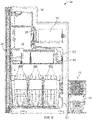
- An airflow path 48 extends between the heat exchanger 40 and the lower ends 42B of each ventilation duct 42. More particularly, the airflow path 48 includes a vertically extending section adjacent to the heat exchanger 40. The air from within the refrigerator 10 that is directed into the airflow path 48 by a cooling fan 52 is cooled within the vertically extending portion of the airflow path 48.
- the airflow path 48 also include a horizontally extending portion below the freezer 28 that extends between the vertically extending portion and the ventilation ducts 42.
- a guide blade 50 is provided at the lower end 42 of the ventilation ducts 42 to assist with the transition of airflow from the airflow path 48 to the ventilation ducts 42.
- the cooling fan 52 is disposed within the interior 18 of the refrigerator 10. As illustrated, the cooling fan 52 is located horizontally behind the middle drawer 24 between the middle drawer 24 and the heat exchanger 40. In this regard, the cooling fan 52 may be mounted on a forwardly facing wall defining a portion of the airflow path 42 immediately behind the middle drawer 24. In other applications, the cooling fan 52 may be mounted to and carried by the middle drawer 24.
- the cooling fan 52 operates to direct a source of air across the heat exchanger 40, along the airflow path 48, through the at least one ventilation duct 42 and into the upper zone 18A of the interior 18 of the refrigerator 10. Cooling air may also be directed in an opposite, downward direction. The direction of air drawn into the cooling fan 52 is shown at arrow 54.
- the other arrows of Figure 4 show the flow of cooled air from the heat exchanger 52. As shown in Figure 3 , the cooling fan 52 may be oriented upwardly to direct a greater amount of cooled air to the upper zone 18B of the interior 18.
- the cooling fan 52 may be controlled to direct air against the heat exchanger 40 for cooling, upwardly along the airflow path 48, through the ventilation ducts 42 of the refrigerator door 28 and into the upper zone 18B of the interior 18 of the refrigerator 10.
- the upper ends 42A of the ventilation ducts 42 may be in a front face of the freezer door 28. Air may also be directed downwardly from the heat exchanger 40. In this manner, internal airflow within the refrigerator 10 may be optimized to ensure that the various zones of the refrigerator 10 are efficiently cooled.
- the cooling fan 52 may be controlled to run both with and without operation of the compressor. In certain applications, it may be desired to continuously or almost continuously operate the cooling fan 52 to provide sufficient cooling to the upper zone 18 without overcooling other zones of the refrigerator.
- the present teachings provide a solution for efficiently cooling an upper zone 18B of the interior 18 where the heat exchanger 40 is centrally located within the refrigerator 10 while avoiding the incorporation of complicated air ducting. This solution also provides a clean and desirable appearance within the refrigerator 10.
- the upper zone 18B of the interior 18 may be maintained within a desired temperature range between 0 and 8 degrees Celsius.
- the cooling unit housing 38 is located at a rear side 58 of the refrigerator 10.
- the cooling unit housing 38 may have a U-shaped sidewall 56 having a first or top wall 56A, a second or bottom wall 56B and a third or intermediate side wall 56C connecting the top and bottom walls 56A and 56B.
- the first and third side walls 56A and 56C may be formed together.
- the second side wall 56B may be separately formed and may define a floor of the cooling unit 16.
- the sidewall 56 cooling unit housing 38 is open to an interior 60 of the cooling unit 16 at an open side 61.
- the open side 61 is located at a lateral side of the refrigerator 10.
- the cooling unit housing 38 defines an airflow path 62.
- the airflow path may be a U-shaped airflow path 62 extending between an inlet 64 and an outlet 66.
- the inlet and the outlet 64 and 66 are located at a common lateral side of the refrigerator 10.
- the refrigerator of includes a side vent 68 removably attached to the cooling unit housing 38 and covering the inlet and the outlet 64 and 66. As the removable side vent 68 is located on the lateral side of the refrigerator 10, the components of the cooling unit 16 may be more easily accessed for diagnosis and repair from an interior of the vehicle without removing the refrigerator 10.
- the cooling unit 16 may also include a removable shell 63 that closes an open rear side of the cooling unit housing 38.
- the airflow path 62 includes a first portion 62A horizontally extending into the cooling unit housing 38 from the inlet 64 and a second portion 66B horizontally extending to the outlet 66.
- An arcuate portion 62C connects the first and second portions 62A and 62B.
- a divider wall 70 is horizontally oriented in the cooling unit housing 38 and separates the first and second portions 62A and 62B of the airflow path 62.
- the compressor 30 is disposed within the first portion of the airflow path 62A.
- the condenser 36 is disposed in the second portion 62B of the airflow path 62.
- the ventilator 32 located in the airflow path 62 at a transition between the third portion 62C and the second portion 62B.
- the refrigerator 10 of the present teachings including cooling unit 16 provides the added benefit of a more secure fixation to the vehicle.
- the installation point is freely accessible from the side, the installation point can be adapted per vehicle, making a stronger connection between the refrigerator 10 and the vehicle possible.
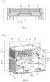
- FIG. 7 and 8 another refrigerator in accordance with the present teachings is illustrated and generally identified at reference character 100. Given the similarities between the refrigerator 100 and the refrigerator 10, like reference characters will be used throughout the drawings to identify like elements.
- the refrigerator 100 of Figures 7 and 8 primarily differs from the refrigerator 10 of Figures 1-6 by incorporating a smaller, metal housing 102 instead of a larger, plastic housing 38. This metal housing 102 is shown removed in Figure 8 for purposes of illustration.
- the cooling unit housing 38 is located at a rear side 58 of the refrigerator 10.
- the cooling unit housing 38 may have a U-shaped sidewall 56 having a first or top wall 56A, a second or bottom wall 56B and a third or intermediate side wall 56C connecting the top and bottom walls 56A and 56B.
- the first and third side walls 56A and 56C may be formed together.
- the second side wall 56B may be separately formed and may define a floor of the cooling unit 16.
- the cooling unit housing 38 is open to an interior 60 of the cooling unit housing 56 at an open side 61.
- the open side 61 is located at a lateral side of the refrigerator 10.
- the cooling unit housing 102 defines an airflow path 62.
- the airflow path may be a U-shaped airflow path 62 extending between an inlet 64 and an outlet 66.
- the inlet and the outlet 64 and 66 are located at a common lateral side of the refrigerator 10.
- the airflow path 62 includes a first portion 62A horizontally extending into the cooling unit housing 56 from the inlet 64 and a second portion 66B horizontally extending to the outlet 66.
- An intermediate portion 62C connects the first and second portions 62A and 62B.
- the housing 102 may rear wall and a top wall that cooperate with the ventilator 32 to include the condenser 36. To the extent not otherwise described, it will be understood that the airflow of the cooling unit 16 of the refrigerator 100 is identical to the refrigerator 10.
- U-shaped as used herein is not limited to a shape with two parallel legs and an accurate intermediate portion. Rather, this term will be understood to encompass any shape with two legs either parallel are slightly askew to one another and an intermediate portion that connects the two legs.
- the intermediate portion may be arcuate, straight or otherwise.
Landscapes
- Engineering & Computer Science (AREA)
- Chemical & Material Sciences (AREA)
- Combustion & Propulsion (AREA)
- Physics & Mathematics (AREA)
- Mechanical Engineering (AREA)
- Thermal Sciences (AREA)
- General Engineering & Computer Science (AREA)
- Devices That Are Associated With Refrigeration Equipment (AREA)
- Cold Air Circulating Systems And Constructional Details In Refrigerators (AREA)
Abstract
Description
- The present disclosure relates generally to refrigerators. More particularly, the present disclosure relates to various aspects of a refrigerator applicable for vehicle and non-vehicle applications.
- This section merely provides background information related to the present disclosure and may not constitute prior art.
- Vehicles, including but not limited to, camper vans, recreational vehicles ("RVs", in the United States and "Caravans" or "Mobile Homes" in Europe), trucks, tractor trailers, airplanes, boats, trains and the like, often incorporate refrigerators for the comfort and convenience of the occupants. For example, campers often find it convenient, or even necessary, to refrigerate food, drinks, and medicine during their journey and while at their campsites. Thus, a popular solution has been to equip the recreational vehicle with a refrigerator.
- Known refrigerators for vehicles have proven to be generally acceptable for their intended uses. A continuous need for improvement to vehicle refrigerators and other refrigerators, however, is always desired.
- This section provides a general summary of the disclosure, and is not a comprehensive disclosure of its full scope or all of its features.
- It is a general object of the present teachings to provide more efficient cooling for an upper zone of the refrigerator.
- It is a more particular, related object of the present teachings to provide air ducts that extend through a freezer door to route cooling air from an evaporator section of the refrigerator to an upper zone of the refrigerator.
- It is another general object of the present teachings to provide a refrigerator having a cooling unit that has better performance with lower energy consumption, is faster to install, has reduced noise, is easier to service and is easier to diagnose.
- In accordance with one particular aspect, the present teachings provide a refrigerator including a housing defining an interior, a freezer disposed within the interior, and a cooling unit for cooling the interior of the refrigerator. The freezer has a freezer door. The cooling unit includes a heat exchanger disposed within the interior of the housing. At least one ventilation duct vertically extends through the freezer door. The at least one ventilation duct has a first end in communication with an upper zone of the interior of the refrigerator. An airflow path extends between the heat exchanger and a lower end of the at least one ventilation duct. A cooling fan is disposed within the interior of the refrigerator for directing a source of air across the heat exchanger, along the airflow path, through the at least one ventilation duct and into the upper zone of the interior of the refrigerator.
- In accordance with another particular aspect, the present teachings provide a refrigerator a housing defining an interior, a heat exchanger disposed in the interior, and a cooling unit for cooling the interior. The cooling unit includes a cooling unit housing located at a rear side of the refrigerator. The cooling unit housing defines a U-shaped airflow path extending between an inlet and an outlet. The inlet and the outlet are located at a common lateral side of the refrigerator.
- Further areas of applicability will become apparent from the description provided herein. The description and specific examples in this summary are intended for purposes of illustration only and are not intended to limit the scope of the present disclosure.
- The present teachings will become more fully understood from the detailed description, any appended claims and the following drawings. The drawings are for illustrative purposes only and are not intended to limit the scope of the present disclosure.
-
Figure 1 is a perspective view of a refrigerator in accordance with the present teachings, the refrigerator shown built into a cabinet of a motor vehicle such as a caravan. -
Figure 2 is another perspective view of the refrigerator of the present teachings. -
Figure 3 is cross-sectional view taken through the refrigerator. -
Figure 4 is a simplified cross-sectional view similar toFigure 3 illustrating the air flow within the refrigerator. -
Figure 5 is a cross-sectional view taken through a freezer door of the refrigerator. -
Figure 6 is a rear perspective view of a portion of the refrigerator in accordance with the present teachings. -
Figure 7 is a perspective view of another refrigerator in accordance with the present teachings. -
Figure 8 is a perspective view of the refrigerator ofFigure 7 shown with a cover of the cooling unit removed for purposes of illustration. - The following description is merely exemplary in nature and is not intended to limit the present disclosure, its application, or uses. It should be understood that throughout the drawings, corresponding reference numerals indicate like or corresponding parts and features.
- With general reference to the
Figures 1-6 of the drawings, a refrigerator constructed in accordance with the present teachings is illustrated and generally identified atreference character 10. As will be further appreciated below, the present teachings provide arefrigerator 10 particular suitable for use within a caravan or other vehicle. It will be understood, however, that the present teachings are not so limited and may be adapted for other, non-mobile applications. InFigure 1 , therefrigerator 10 is shown built into acabinet 12 of a motor vehicle. - Before addressing the particular aspects of the present teachings, a more general description of the refrigerator shown throughout the drawings is warranted. The
refrigerator 10 is shown to generally include ahousing 14 and acooling unit 16 for cooling aninterior 18 of thehousing 14. Theinterior 18 of thehousing 14 is accessed through arefrigerator door 20 pivotally connected to thehousing 14 in a conventional manner. In the embodiment illustrated, therefrigerator 10 includes asingle door 20. In other embodiments within the scope of the present teachings, therefrigerator 10 may include two or more doors. Therefrigerator 10 may include abottom drawer 22, amiddle drawer 24, adoor bin 26 and afreezer 28. Thebottom drawer 22 may be slidably disposed in alower zone 18A of theinterior 18 of therefrigerator 10. Thedoor bin 26 may be carried by thedoor 20 and disposed in anupper zone 18B of theinterior 18 of therefrigerator 10. Themiddle drawer 24 may be vertically located between thebottom drawer 22 and thedoor bin 26 in an intermediate zone 18C of theinterior 18 of therefrigerator 10. Thefreezer 28 may be normally closed by afreezer door 29. As illustrated, access to thefreezer door 28 is horizontally behind theupper zone 18B of theinterior 18 of therefrigerator 10. - The
cooling unit 16 of therefrigerator 10 generally includes acompressor 30, aventilator 32, acondensation tray 34, and acondenser 36. In the embodiment illustrated, the condenser is a wire-style condenser 36. The various components of thecooling unit 16 may be housed within acooling unit housing 38. Thecondenser 36 is in operative communication with a heat exchanger orevaporator 40 located a rear of the interior of therefrigerator 10. - The present teachings provide for more efficient cooling of the
upper zone 18B of theinterior 18 with at least oneventilation duct 42 that vertically extends through thefreezer door 28. As shown perhaps most particularly in the cross section ofFigure 5 , in the embodiment illustrated thefreezer door 28 includes a pair ofventilation ducts 42 vertically extending through thefreezer door 28. Thefreezer door 28 may define a freezer handle. The at least oneventilation duct 42 may pass through the freezer handle. An interior 44 of thefreezer door 28 is otherwise shown foamed with aninsulation 46. - Each
ventilation duct 42 has a first orupper end 42A in communication with theupper zone 18B of the interior 18 of therefrigerator 10 and a second orlower end 42B. Anairflow path 48 extends between theheat exchanger 40 and the lower ends 42B of eachventilation duct 42. More particularly, theairflow path 48 includes a vertically extending section adjacent to theheat exchanger 40. The air from within therefrigerator 10 that is directed into theairflow path 48 by a coolingfan 52 is cooled within the vertically extending portion of theairflow path 48. Theairflow path 48 also include a horizontally extending portion below thefreezer 28 that extends between the vertically extending portion and theventilation ducts 42. Aguide blade 50 is provided at thelower end 42 of theventilation ducts 42 to assist with the transition of airflow from theairflow path 48 to theventilation ducts 42. - The cooling
fan 52 is disposed within theinterior 18 of therefrigerator 10. As illustrated, the coolingfan 52 is located horizontally behind themiddle drawer 24 between themiddle drawer 24 and theheat exchanger 40. In this regard, the coolingfan 52 may be mounted on a forwardly facing wall defining a portion of theairflow path 42 immediately behind themiddle drawer 24. In other applications, the coolingfan 52 may be mounted to and carried by themiddle drawer 24. The coolingfan 52 operates to direct a source of air across theheat exchanger 40, along theairflow path 48, through the at least oneventilation duct 42 and into theupper zone 18A of the interior 18 of therefrigerator 10. Cooling air may also be directed in an opposite, downward direction. The direction of air drawn into the coolingfan 52 is shown atarrow 54. The other arrows ofFigure 4 show the flow of cooled air from theheat exchanger 52. As shown inFigure 3 , the coolingfan 52 may be oriented upwardly to direct a greater amount of cooled air to theupper zone 18B of the interior 18. - In operation, the cooling
fan 52 may be controlled to direct air against theheat exchanger 40 for cooling, upwardly along theairflow path 48, through theventilation ducts 42 of therefrigerator door 28 and into theupper zone 18B of the interior 18 of therefrigerator 10. As shown inFigure 4 , the upper ends 42A of theventilation ducts 42 may be in a front face of thefreezer door 28. Air may also be directed downwardly from theheat exchanger 40. In this manner, internal airflow within therefrigerator 10 may be optimized to ensure that the various zones of therefrigerator 10 are efficiently cooled. The coolingfan 52 may be controlled to run both with and without operation of the compressor. In certain applications, it may be desired to continuously or almost continuously operate the coolingfan 52 to provide sufficient cooling to theupper zone 18 without overcooling other zones of the refrigerator. - The present teachings provide a solution for efficiently cooling an
upper zone 18B of the interior 18 where theheat exchanger 40 is centrally located within therefrigerator 10 while avoiding the incorporation of complicated air ducting. This solution also provides a clean and desirable appearance within therefrigerator 10. In one application, theupper zone 18B of the interior 18 may be maintained within a desired temperature range between 0 and 8 degrees Celsius. - The cooling
unit housing 38 is located at arear side 58 of therefrigerator 10. In the embodiment illustrated, the coolingunit housing 38 may have aU-shaped sidewall 56 having a first ortop wall 56A, a second orbottom wall 56B and a third or intermediate side wall 56C connecting the top andbottom walls third side walls 56A and 56C may be formed together. Thesecond side wall 56B may be separately formed and may define a floor of the coolingunit 16. Thesidewall 56cooling unit housing 38 is open to an interior 60 of the coolingunit 16 at anopen side 61. Theopen side 61 is located at a lateral side of therefrigerator 10. - The cooling
unit housing 38 defines anairflow path 62. The airflow path may be aU-shaped airflow path 62 extending between aninlet 64 and anoutlet 66. The inlet and theoutlet refrigerator 10. The refrigerator of includes aside vent 68 removably attached to thecooling unit housing 38 and covering the inlet and theoutlet removable side vent 68 is located on the lateral side of therefrigerator 10, the components of the coolingunit 16 may be more easily accessed for diagnosis and repair from an interior of the vehicle without removing therefrigerator 10. The coolingunit 16 may also include aremovable shell 63 that closes an open rear side of thecooling unit housing 38. - The
airflow path 62 includes afirst portion 62A horizontally extending into thecooling unit housing 38 from theinlet 64 and a second portion 66B horizontally extending to theoutlet 66. Anarcuate portion 62C connects the first andsecond portions cooling unit housing 38 and separates the first andsecond portions airflow path 62. Thecompressor 30 is disposed within the first portion of theairflow path 62A. Thecondenser 36 is disposed in thesecond portion 62B of theairflow path 62. Theventilator 32 located in theairflow path 62 at a transition between thethird portion 62C and thesecond portion 62B. - The
refrigerator 10 of the present teachings including coolingunit 16 provides the added benefit of a more secure fixation to the vehicle. As the installation point is freely accessible from the side, the installation point can be adapted per vehicle, making a stronger connection between therefrigerator 10 and the vehicle possible. - Turning to
Figures 7 and8 , another refrigerator in accordance with the present teachings is illustrated and generally identified atreference character 100. Given the similarities between therefrigerator 100 and therefrigerator 10, like reference characters will be used throughout the drawings to identify like elements. Therefrigerator 100 ofFigures 7 and8 primarily differs from therefrigerator 10 ofFigures 1-6 by incorporating a smaller,metal housing 102 instead of a larger,plastic housing 38. Thismetal housing 102 is shown removed inFigure 8 for purposes of illustration. - The cooling
unit housing 38 is located at arear side 58 of therefrigerator 10. In the embodiment illustrated, the coolingunit housing 38 may have aU-shaped sidewall 56 having a first ortop wall 56A, a second orbottom wall 56B and a third or intermediate side wall 56C connecting the top andbottom walls third side walls 56A and 56C may be formed together. Thesecond side wall 56B may be separately formed and may define a floor of the coolingunit 16. The coolingunit housing 38 is open to an interior 60 of thecooling unit housing 56 at anopen side 61. Theopen side 61 is located at a lateral side of therefrigerator 10. - As with the
refrigerator 10, the coolingunit housing 102 defines anairflow path 62. The airflow path may be aU-shaped airflow path 62 extending between aninlet 64 and anoutlet 66. The inlet and theoutlet refrigerator 10. Theairflow path 62 includes afirst portion 62A horizontally extending into thecooling unit housing 56 from theinlet 64 and a second portion 66B horizontally extending to theoutlet 66. Anintermediate portion 62C connects the first andsecond portions - As illustrated in the particular embodiment shown, the
housing 102 may rear wall and a top wall that cooperate with theventilator 32 to include thecondenser 36. To the extent not otherwise described, it will be understood that the airflow of the coolingunit 16 of therefrigerator 100 is identical to therefrigerator 10. - While specific examples have been discussed in the specification and illustrated in the drawings, it will be understood by those skilled in the art that various changes may be made and equivalence may be substituted for elements thereof without departing from the scope of the present teachings. Additionally, while the present teachings may have particular application for motor vehicles, the scope is limited in this regard. For example, various aspects of the present teachings may be readily adapted for refrigerators used in stationary applications, including but not limited to commercial and residential refrigerators. Furthermore, the mixing and matching of features, elements and/or functions between various examples may be expressly contemplated herein so that one skilled in the art would appreciate from the present teachings that features, elements and/or functions of one example may be incorporated into another example as appropriate, unless discussed otherwise above. Moreover, many modifications may be made to adapt a particular situation or material to the present teachings without departing from the essential scope thereof. Therefore, it may be intended that the present teachings not be limited to the particular examples illustrated by the drawings and discussed in the specification as the best mode of presently contemplated for carrying out the present teachings but that the scope of the present disclosure will include any embodiments following within the foregoing description and any appended claims. Finally, it will be understood that the term U-shaped as used herein is not limited to a shape with two parallel legs and an accurate intermediate portion. Rather, this term will be understood to encompass any shape with two legs either parallel are slightly askew to one another and an intermediate portion that connects the two legs. The intermediate portion may be arcuate, straight or otherwise.
Claims (19)
- A refrigerator comprising:a housing defining an interior;a freezer disposed within the interior and having a freezer door;a cooling unit for cooling the interior of the refrigerator, the cooling unit including a heat exchanger disposed within the interior of the housing;at least one ventilation duct vertically extending through the freezer door, the at least one ventilation duct having a first end in communication with an upper zone of the interior of the refrigerator;an airflow path extending between the heat exchanger and a lower end of the at least one ventilation duct; anda cooling fan for directing a source of air across the heat exchanger, along the airflow path, through the at least one ventilation duct and into the upper zone of the interior of the refrigerator.
- The refrigerator of claim 1, wherein the at least one ventilation duct includes first and second ventilation ducts.
- The refrigerator of claim 1, wherein the upper end at least one ventilation duct is in the front face of the freezer door.
- The refrigerator of claim 1, wherein the airflow path 48 includes a vertically extending section adjacent to the heat exchanger.
- The refrigerator of claim 4, wherein the airflow path also includes a horizontally extending portion below the freezer that extends between the vertically extending portion and the at least one ventilation duct.
- The refrigerator of claim 5, further comprising a guide blade at the lower end of the at least one ventilation duct to assist with the transition of airflow from the airflow path to the ventilation ducts.
- The refrigerator of claim 1, wherein the freezer door defines a freezer handle and the at least one ventilation duct extends through the freezer handle.
- The refrigerator of claim 1, wherein the cooling fan is angled upwardly.
- The refrigerator of claim 1, wherein the upper zone of the interior is completely above the heat exchanger such that cooled air from the heat exchanger is routed upward to the upper zone.
- A refrigerator comprising:a housing defining an interior;a heat exchanger disposed in the interior; anda cooling unit for cooling the interior, the cooling unit including a cooling unit housing located at a rear side of the refrigerator, the cooling unit housing defining a U-shaped airflow path extending between an inlet and an outlet, the inlet and the outlet located at a common lateral side of the refrigerator.
- The refrigerator of claim 10, further comprising a side vent removably attached to the housing and covering the inlet and the outlet.
- The refrigerator of claim 10, wherein airflow path includes a first portion horizontally extending into the housing from the inlet and a second portion horizontally extending to the outlet.
- The refrigerator of claim 12, wherein cooling unit includes a compressor disposed within the first portion of the airflow path.
- The refrigerator of claim 13, wherein cooling unit includes a condensor disposed in the second portion of the airflow path.
- The refrigerator of claim 14, wherein the condenser is a wire-style condenser.
- The refrigerator of claim 14, wherein the condenser is operatively associated with the heat exchanger.
- The refrigerator of claim 13, wherein the cooling unit further includes a ventilator located in the airflow path.
- The refrigerator of claim 12, wherein the cooling unit further includes a divider wall horizontally oriented in the cooling unit housing and separating the first and second portions of the airflow path.
- The refrigerator of claim 10, wherein the refrigerator may be firmly secured to a vehicle as the installation point is freely accessible from a side of the refrigerator.
Applications Claiming Priority (2)
| Application Number | Priority Date | Filing Date | Title |
|---|---|---|---|
| US202163236807P | 2021-08-25 | 2021-08-25 | |
| US17/892,196 US12292224B2 (en) | 2021-08-25 | 2022-08-22 | Refrigerator |
Publications (4)
| Publication Number | Publication Date |
|---|---|
| EP4141359A2 true EP4141359A2 (en) | 2023-03-01 |
| EP4141359A3 EP4141359A3 (en) | 2023-04-26 |
| EP4141359C0 EP4141359C0 (en) | 2025-08-06 |
| EP4141359B1 EP4141359B1 (en) | 2025-08-06 |
Family
ID=85025249
Family Applications (1)
| Application Number | Title | Priority Date | Filing Date |
|---|---|---|---|
| EP22020409.3A Active EP4141359B1 (en) | 2021-08-25 | 2022-08-24 | Refrigerator |
Country Status (4)
| Country | Link |
|---|---|
| US (1) | US12292224B2 (en) |
| EP (1) | EP4141359B1 (en) |
| CN (1) | CN115727609B (en) |
| AU (2) | AU2022221455B2 (en) |
Family Cites Families (10)
| Publication number | Priority date | Publication date | Assignee | Title |
|---|---|---|---|---|
| US2692482A (en) * | 1951-06-07 | 1954-10-26 | Philco Corp | Multitemperature refrigerator |
| US2745259A (en) | 1955-02-14 | 1956-05-15 | Gen Motors Corp | Refrigerator with means to cool shelves adjacent an insulated freezing compartment |
| SU1559243A1 (en) | 1988-03-09 | 1990-04-23 | Предприятие П/Я В-8906 | Two-compartment refrigerator |
| JPH0634248A (en) * | 1992-07-22 | 1994-02-08 | Mitsubishi Heavy Ind Ltd | Transporting refrigerator |
| US6058734A (en) * | 1998-12-15 | 2000-05-09 | Daewoo Electronics Co., Ltd. | Refrigerator provided with cooled air bypass passages |
| KR100333532B1 (en) * | 2000-03-29 | 2002-04-25 | 전주범 | refrigerator having a bell mouth of cold storage room-fan with integral lining |
| KR100621038B1 (en) * | 2003-09-19 | 2006-09-08 | 엘지전자 주식회사 | Refrigerator |
| KR100584270B1 (en) * | 2004-03-24 | 2006-05-26 | 엘지전자 주식회사 | Deicing cold air flow path structure of bottom freezer type refrigerator |
| CN103069228B (en) | 2010-03-05 | 2016-05-25 | 伊莱克斯巴西有限公司 | A kind of system and method for temperature equalization of the door for household electrical appliance |
| EP3109580B1 (en) * | 2015-06-25 | 2021-01-06 | Thetford BV | Compressor refrigerator for a motor vehicle |
-
2022
- 2022-08-22 US US17/892,196 patent/US12292224B2/en active Active
- 2022-08-24 CN CN202211021814.4A patent/CN115727609B/en active Active
- 2022-08-24 AU AU2022221455A patent/AU2022221455B2/en active Active
- 2022-08-24 EP EP22020409.3A patent/EP4141359B1/en active Active
-
2024
- 2024-09-12 AU AU2024219652A patent/AU2024219652A1/en active Pending
Also Published As
| Publication number | Publication date |
|---|---|
| US20230068630A1 (en) | 2023-03-02 |
| AU2024219652A1 (en) | 2024-10-03 |
| EP4141359C0 (en) | 2025-08-06 |
| CN115727609A (en) | 2023-03-03 |
| CN115727609B (en) | 2026-03-24 |
| AU2022221455B2 (en) | 2024-06-13 |
| AU2022221455A1 (en) | 2023-03-16 |
| EP4141359A3 (en) | 2023-04-26 |
| US12292224B2 (en) | 2025-05-06 |
| EP4141359B1 (en) | 2025-08-06 |
Similar Documents
| Publication | Publication Date | Title |
|---|---|---|
| US6782944B2 (en) | Air conditioner for vehicles | |
| US8141377B2 (en) | Truck electrified engine-off air conditioning system | |
| US20040261444A1 (en) | Methods and apparatus for refrigerator compartment | |
| JPH0360430U (en) | ||
| US11378325B2 (en) | Refrigerator with noise reduction | |
| US6161609A (en) | Flow control apparatus | |
| JP7207202B2 (en) | vehicle | |
| US2169664A (en) | Refrigeration system | |
| JP2008126800A (en) | Car air conditioner | |
| EP3109580B1 (en) | Compressor refrigerator for a motor vehicle | |
| AU2022221455B2 (en) | Refrigerator | |
| CN114734773B (en) | Car air conditioner host and car | |
| US20050088005A1 (en) | Vehicle storage and ventilation system | |
| CN222845219U (en) | Vehicle-mounted refrigerator system and vehicle | |
| US6942564B1 (en) | Passenger foot duct | |
| CN215621596U (en) | A new type of car with semiconductor refrigeration function storage box | |
| KR101467262B1 (en) | Vehicle air conditioning system | |
| JP2010149566A (en) | Air conditioning device for vehicle | |
| US2807153A (en) | Vehicle refrigerating apparatus | |
| US1946994A (en) | Car cooler | |
| CN220842312U (en) | Vehicle-mounted cooling and heating storage box | |
| JPS6024663Y2 (en) | Console box with refrigerated case | |
| JPS62293073A (en) | Refrigerator | |
| JPS5941135Y2 (en) | Air conditioning system for van type vehicles | |
| KR100931939B1 (en) | Car air conditioner |
Legal Events
| Date | Code | Title | Description |
|---|---|---|---|
| PUAI | Public reference made under article 153(3) epc to a published international application that has entered the european phase |
Free format text: ORIGINAL CODE: 0009012 |
|
| STAA | Information on the status of an ep patent application or granted ep patent |
Free format text: STATUS: THE APPLICATION HAS BEEN PUBLISHED |
|
| AK | Designated contracting states |
Kind code of ref document: A2 Designated state(s): AL AT BE BG CH CY CZ DE DK EE ES FI FR GB GR HR HU IE IS IT LI LT LU LV MC MK MT NL NO PL PT RO RS SE SI SK SM TR |
|
| PUAL | Search report despatched |
Free format text: ORIGINAL CODE: 0009013 |
|
| AK | Designated contracting states |
Kind code of ref document: A3 Designated state(s): AL AT BE BG CH CY CZ DE DK EE ES FI FR GB GR HR HU IE IS IT LI LT LU LV MC MK MT NL NO PL PT RO RS SE SI SK SM TR |
|
| RIC1 | Information provided on ipc code assigned before grant |
Ipc: F25D 17/06 20060101AFI20230320BHEP |
|
| STAA | Information on the status of an ep patent application or granted ep patent |
Free format text: STATUS: REQUEST FOR EXAMINATION WAS MADE |
|
| 17P | Request for examination filed |
Effective date: 20230831 |
|
| RBV | Designated contracting states (corrected) |
Designated state(s): AL AT BE BG CH CY CZ DE DK EE ES FI FR GB GR HR HU IE IS IT LI LT LU LV MC MK MT NL NO PL PT RO RS SE SI SK SM TR |
|
| GRAP | Despatch of communication of intention to grant a patent |
Free format text: ORIGINAL CODE: EPIDOSNIGR1 |
|
| STAA | Information on the status of an ep patent application or granted ep patent |
Free format text: STATUS: GRANT OF PATENT IS INTENDED |
|
| INTG | Intention to grant announced |
Effective date: 20250306 |
|
| GRAS | Grant fee paid |
Free format text: ORIGINAL CODE: EPIDOSNIGR3 |
|
| GRAA | (expected) grant |
Free format text: ORIGINAL CODE: 0009210 |
|
| STAA | Information on the status of an ep patent application or granted ep patent |
Free format text: STATUS: THE PATENT HAS BEEN GRANTED |
|
| AK | Designated contracting states |
Kind code of ref document: B1 Designated state(s): AL AT BE BG CH CY CZ DE DK EE ES FI FR GB GR HR HU IE IS IT LI LT LU LV MC MK MT NL NO PL PT RO RS SE SI SK SM TR |
|
| REG | Reference to a national code |
Ref country code: GB Ref legal event code: FG4D |
|
| REG | Reference to a national code |
Ref country code: CH Ref legal event code: EP |
|
| REG | Reference to a national code |
Ref country code: DE Ref legal event code: R096 Ref document number: 602022018681 Country of ref document: DE |
|
| REG | Reference to a national code |
Ref country code: IE Ref legal event code: FG4D |
|
| U01 | Request for unitary effect filed |
Effective date: 20250905 |
|
| PGFP | Annual fee paid to national office [announced via postgrant information from national office to epo] |
Ref country code: AT Payment date: 20251020 Year of fee payment: 4 |
|
| U07 | Unitary effect registered |
Designated state(s): AT BE BG DE DK EE FI FR IT LT LU LV MT NL PT RO SE SI Effective date: 20250926 |
|
| U20 | Renewal fee for the european patent with unitary effect paid |
Year of fee payment: 4 Effective date: 20250929 |
|
| PG25 | Lapsed in a contracting state [announced via postgrant information from national office to epo] |
Ref country code: IS Free format text: LAPSE BECAUSE OF FAILURE TO SUBMIT A TRANSLATION OF THE DESCRIPTION OR TO PAY THE FEE WITHIN THE PRESCRIBED TIME-LIMIT Effective date: 20251206 |
|
| PG25 | Lapsed in a contracting state [announced via postgrant information from national office to epo] |
Ref country code: NO Free format text: LAPSE BECAUSE OF FAILURE TO SUBMIT A TRANSLATION OF THE DESCRIPTION OR TO PAY THE FEE WITHIN THE PRESCRIBED TIME-LIMIT Effective date: 20251106 |
|
| PG25 | Lapsed in a contracting state [announced via postgrant information from national office to epo] |
Ref country code: HR Free format text: LAPSE BECAUSE OF FAILURE TO SUBMIT A TRANSLATION OF THE DESCRIPTION OR TO PAY THE FEE WITHIN THE PRESCRIBED TIME-LIMIT Effective date: 20250806 |
|
| PG25 | Lapsed in a contracting state [announced via postgrant information from national office to epo] |
Ref country code: GR Free format text: LAPSE BECAUSE OF FAILURE TO SUBMIT A TRANSLATION OF THE DESCRIPTION OR TO PAY THE FEE WITHIN THE PRESCRIBED TIME-LIMIT Effective date: 20251107 |
|
| PG25 | Lapsed in a contracting state [announced via postgrant information from national office to epo] |
Ref country code: PL Free format text: LAPSE BECAUSE OF FAILURE TO SUBMIT A TRANSLATION OF THE DESCRIPTION OR TO PAY THE FEE WITHIN THE PRESCRIBED TIME-LIMIT Effective date: 20250806 |
|
| PG25 | Lapsed in a contracting state [announced via postgrant information from national office to epo] |
Ref country code: RS Free format text: LAPSE BECAUSE OF FAILURE TO SUBMIT A TRANSLATION OF THE DESCRIPTION OR TO PAY THE FEE WITHIN THE PRESCRIBED TIME-LIMIT Effective date: 20251106 |
|
| PG25 | Lapsed in a contracting state [announced via postgrant information from national office to epo] |
Ref country code: ES Free format text: LAPSE BECAUSE OF FAILURE TO SUBMIT A TRANSLATION OF THE DESCRIPTION OR TO PAY THE FEE WITHIN THE PRESCRIBED TIME-LIMIT Effective date: 20250806 |
|
| PGFP | Annual fee paid to national office [announced via postgrant information from national office to epo] |
Ref country code: HU Payment date: 20250822 Year of fee payment: 4 |
|
| REG | Reference to a national code |
Ref country code: CH Ref legal event code: H13 Free format text: ST27 STATUS EVENT CODE: U-0-0-H10-H13 (AS PROVIDED BY THE NATIONAL OFFICE) Effective date: 20260324 |
|
| PG25 | Lapsed in a contracting state [announced via postgrant information from national office to epo] |
Ref country code: SM Free format text: LAPSE BECAUSE OF FAILURE TO SUBMIT A TRANSLATION OF THE DESCRIPTION OR TO PAY THE FEE WITHIN THE PRESCRIBED TIME-LIMIT Effective date: 20250806 |
|
| PG25 | Lapsed in a contracting state [announced via postgrant information from national office to epo] |
Ref country code: CZ Free format text: LAPSE BECAUSE OF FAILURE TO SUBMIT A TRANSLATION OF THE DESCRIPTION OR TO PAY THE FEE WITHIN THE PRESCRIBED TIME-LIMIT Effective date: 20250806 Ref country code: CH Free format text: LAPSE BECAUSE OF NON-PAYMENT OF DUE FEES Effective date: 20250831 |
|
| PG25 | Lapsed in a contracting state [announced via postgrant information from national office to epo] |
Ref country code: SK Free format text: LAPSE BECAUSE OF FAILURE TO SUBMIT A TRANSLATION OF THE DESCRIPTION OR TO PAY THE FEE WITHIN THE PRESCRIBED TIME-LIMIT Effective date: 20250806 |