EP4141300A1 - Valve actuator - Google Patents
Valve actuator Download PDFInfo
- Publication number
- EP4141300A1 EP4141300A1 EP22189401.7A EP22189401A EP4141300A1 EP 4141300 A1 EP4141300 A1 EP 4141300A1 EP 22189401 A EP22189401 A EP 22189401A EP 4141300 A1 EP4141300 A1 EP 4141300A1
- Authority
- EP
- European Patent Office
- Prior art keywords
- gear
- output
- valve
- valve actuator
- output gear
- Prior art date
- Legal status (The legal status is an assumption and is not a legal conclusion. Google has not performed a legal analysis and makes no representation as to the accuracy of the status listed.)
- Granted
Links
Images




Classifications
-
- F—MECHANICAL ENGINEERING; LIGHTING; HEATING; WEAPONS; BLASTING
- F16—ENGINEERING ELEMENTS AND UNITS; GENERAL MEASURES FOR PRODUCING AND MAINTAINING EFFECTIVE FUNCTIONING OF MACHINES OR INSTALLATIONS; THERMAL INSULATION IN GENERAL
- F16K—VALVES; TAPS; COCKS; ACTUATING-FLOATS; DEVICES FOR VENTING OR AERATING
- F16K31/00—Actuating devices; Operating means; Releasing devices
- F16K31/02—Actuating devices; Operating means; Releasing devices electric; magnetic
- F16K31/04—Actuating devices; Operating means; Releasing devices electric; magnetic using a motor
- F16K31/041—Actuating devices; Operating means; Releasing devices electric; magnetic using a motor for rotating valves
- F16K31/043—Actuating devices; Operating means; Releasing devices electric; magnetic using a motor for rotating valves characterised by mechanical means between the motor and the valve, e.g. lost motion means reducing backlash, clutches, brakes or return means
-
- F—MECHANICAL ENGINEERING; LIGHTING; HEATING; WEAPONS; BLASTING
- F16—ENGINEERING ELEMENTS AND UNITS; GENERAL MEASURES FOR PRODUCING AND MAINTAINING EFFECTIVE FUNCTIONING OF MACHINES OR INSTALLATIONS; THERMAL INSULATION IN GENERAL
- F16K—VALVES; TAPS; COCKS; ACTUATING-FLOATS; DEVICES FOR VENTING OR AERATING
- F16K1/00—Lift valves or globe valves, i.e. cut-off apparatus with closure members having at least a component of their opening and closing motion perpendicular to the closing faces
- F16K1/14—Lift valves or globe valves, i.e. cut-off apparatus with closure members having at least a component of their opening and closing motion perpendicular to the closing faces with ball-shaped valve member
-
- F—MECHANICAL ENGINEERING; LIGHTING; HEATING; WEAPONS; BLASTING
- F16—ENGINEERING ELEMENTS AND UNITS; GENERAL MEASURES FOR PRODUCING AND MAINTAINING EFFECTIVE FUNCTIONING OF MACHINES OR INSTALLATIONS; THERMAL INSULATION IN GENERAL
- F16K—VALVES; TAPS; COCKS; ACTUATING-FLOATS; DEVICES FOR VENTING OR AERATING
- F16K31/00—Actuating devices; Operating means; Releasing devices
- F16K31/44—Mechanical actuating means
- F16K31/53—Mechanical actuating means with toothed gearing
-
- F—MECHANICAL ENGINEERING; LIGHTING; HEATING; WEAPONS; BLASTING
- F16—ENGINEERING ELEMENTS AND UNITS; GENERAL MEASURES FOR PRODUCING AND MAINTAINING EFFECTIVE FUNCTIONING OF MACHINES OR INSTALLATIONS; THERMAL INSULATION IN GENERAL
- F16H—GEARING
- F16H57/00—General details of gearing
- F16H57/02—Gearboxes; Mounting gearing therein
-
- F—MECHANICAL ENGINEERING; LIGHTING; HEATING; WEAPONS; BLASTING
- F16—ENGINEERING ELEMENTS AND UNITS; GENERAL MEASURES FOR PRODUCING AND MAINTAINING EFFECTIVE FUNCTIONING OF MACHINES OR INSTALLATIONS; THERMAL INSULATION IN GENERAL
- F16K—VALVES; TAPS; COCKS; ACTUATING-FLOATS; DEVICES FOR VENTING OR AERATING
- F16K27/00—Construction of housing; Use of materials therefor
-
- F—MECHANICAL ENGINEERING; LIGHTING; HEATING; WEAPONS; BLASTING
- F16—ENGINEERING ELEMENTS AND UNITS; GENERAL MEASURES FOR PRODUCING AND MAINTAINING EFFECTIVE FUNCTIONING OF MACHINES OR INSTALLATIONS; THERMAL INSULATION IN GENERAL
- F16K—VALVES; TAPS; COCKS; ACTUATING-FLOATS; DEVICES FOR VENTING OR AERATING
- F16K31/00—Actuating devices; Operating means; Releasing devices
- F16K31/02—Actuating devices; Operating means; Releasing devices electric; magnetic
- F16K31/04—Actuating devices; Operating means; Releasing devices electric; magnetic using a motor
-
- F—MECHANICAL ENGINEERING; LIGHTING; HEATING; WEAPONS; BLASTING
- F16—ENGINEERING ELEMENTS AND UNITS; GENERAL MEASURES FOR PRODUCING AND MAINTAINING EFFECTIVE FUNCTIONING OF MACHINES OR INSTALLATIONS; THERMAL INSULATION IN GENERAL
- F16K—VALVES; TAPS; COCKS; ACTUATING-FLOATS; DEVICES FOR VENTING OR AERATING
- F16K31/00—Actuating devices; Operating means; Releasing devices
- F16K31/02—Actuating devices; Operating means; Releasing devices electric; magnetic
- F16K31/04—Actuating devices; Operating means; Releasing devices electric; magnetic using a motor
- F16K31/047—Actuating devices; Operating means; Releasing devices electric; magnetic using a motor characterised by mechanical means between the motor and the valve, e.g. lost motion means reducing backlash, clutches, brakes or return means
-
- F—MECHANICAL ENGINEERING; LIGHTING; HEATING; WEAPONS; BLASTING
- F16—ENGINEERING ELEMENTS AND UNITS; GENERAL MEASURES FOR PRODUCING AND MAINTAINING EFFECTIVE FUNCTIONING OF MACHINES OR INSTALLATIONS; THERMAL INSULATION IN GENERAL
- F16K—VALVES; TAPS; COCKS; ACTUATING-FLOATS; DEVICES FOR VENTING OR AERATING
- F16K31/00—Actuating devices; Operating means; Releasing devices
- F16K31/44—Mechanical actuating means
- F16K31/53—Mechanical actuating means with toothed gearing
- F16K31/535—Mechanical actuating means with toothed gearing for rotating valves
-
- F—MECHANICAL ENGINEERING; LIGHTING; HEATING; WEAPONS; BLASTING
- F16—ENGINEERING ELEMENTS AND UNITS; GENERAL MEASURES FOR PRODUCING AND MAINTAINING EFFECTIVE FUNCTIONING OF MACHINES OR INSTALLATIONS; THERMAL INSULATION IN GENERAL
- F16K—VALVES; TAPS; COCKS; ACTUATING-FLOATS; DEVICES FOR VENTING OR AERATING
- F16K31/00—Actuating devices; Operating means; Releasing devices
- F16K31/44—Mechanical actuating means
- F16K31/60—Handles
- F16K31/602—Pivoting levers, e.g. single-sided
Definitions
- the present disclosure relates to a valve actuator for automatically opening/closing a valve, and more particularly, to a valve actuator having an over-torque interruption function.
- Refrigerant is essentially used in an air conditioner which is one of the air conditioning devices, and Freon gas used as the refrigerant acts as a factor of global warming.
- refrigerant has been developed, which is not concerned with the global warming, and the newly developed refrigerant does not act as the factor of the global warming, but there is a risk of a fire in the case of refrigerant leakage due to an ignition propensity, and as a result, a valve actuator for automatically actuating a valve for interrupting leakage in the case of the refrigerant leakage has been developed.
- a ball valve 10 As a valve installed between an outdoor unit and an indoor unit of the air conditioner and preventing the refrigerant leakage, a ball valve is primarily used, and as illustrated in FIG. 1 , a ball valve 10 includes a ball 11 with a path, a pipe 12 into which the ball 11 is inserted, a stem 13 connected to the pipe 12, a seal member 14 installed in the stem 13, and a stem fixation bolt 15.
- a valve actuator for controlling the ball valve having such a configuration generally includes a motor and a gear assembly, and controls the valve by controlling rotation of the motor by using a sensor such as a limit switch, etc., or controlling the rotation of the motor by using a step motor.
- Korean Patent Application No. 10-2007-0141333 discloses a valve actuator configured in such a manner that when a projection portion of an output gear connected to the stem of the ball valve among a plurality of gears provided in the gear assembly rotates at 90 degrees or more, an electronic limit switch is pressed to stop the motor.
- valve actuator of the prior patent having the electronic limit switch has a problem in that sensors' peculiar instability in a harsh environment.
- the present disclosure provides a valve actuator capable of securing durability and driving stability.
- the present disclosure also provides a valve actuator removing instability of an electronic sensor.
- the present disclosure also provides a valve actuator which need not include a separate PCB for a motor stop signal.
- a valve actuator includes: a motor; a gear assembly including an input gear rotated by driving force of the motor, an output gear receiving rotational force of the input gear, and at least one power transmission gear transmitting the rotational force of the input gear to the output gear; a valve output shaft coupled to the output gear and configured to be actuated to close a valve; and a selective power transmission unit for interrupting rotation of the output gear after the output gear is rotated at a predetermined angle by the rotational force of the input gear, and the selective power transmission unit includes a lift member releasing meshing of the first gear and the second gear by moving the first gear to an upper side after the output gear is rotated at the predetermined angle or a friction member provided at the output gear so as to brake the rotation of the first gear by contacting the first gear after the output gear is rotated at the predetermined angle.
- the valve actuator may further comprise a case in which the gear assembly is installed.
- the motor may be installed on or outside the case.
- the power transmission gear may include a first gear coupled to the input gear, a second gear coupled to the first gear, and a third gear coupled to each of the second gear and the output gear.
- the selective power transmission unit may include a lift member configured to disengage the first gear from the second gear by the lift member moving and thus pushing the first gear away from the second gear due to interference with a portion of the output gear after the output gear is rotated at the predetermined angle.
- the lift member may include a body connected to the valve output shaft on or above an upper side of the output gear and a lever extended from the body and having an end portion positioned on or below a lower side of the first gear.
- a projection may be formed on one of the output gear and th body, and a groove portion into which the projection is inserted may be formed at the other one of the output gear and the body.
- a guide groove guiding vertical movement of the body may be formed at one of the valve output shaft and the body, and a guide portion inserted into the guide groove may be formed at the other one of the valve output shaft and the body.
- An elastic member pressing the first gear downward may be positioned at an upper side of the first gear.
- a friction pad providing frictional force to the first gear may be formed at the lever or the first gear.
- a friction protrusion providing frictional force to the first gear may be formed at the lever or the first gear.
- the lift member may include a body fixed to a lateral portion of the output gear, and a lever extended from the body and having an end portion positioned on or below a lower side of the first gear.
- the body When the output gear contacts the body, the body may be configured to be deformed so that the lever contacts and pushes the first gear away from the second gear.
- the selective power transmission unit includes a friction member provided at the output gear so as to brake the rotation of the first gear by contact with the first gear after the output gear is rotated at the predetermined angle.
- the output gear is installed at the valve output shaft to be vertically movable.
- a projection portion may be formed at one of the output gear and the case, and an inclined surface on which the projection portion is positioned may be formed at the other one of the output gear and the case.
- Threads which are capalbe of being engaged with each other, may be formed at the output gear and the valve output shaft.
- driving force of a motor is transmitted to a valve output shaft through a gear assembly and a valve is closed, and then the driving force of the motor is not transmitted to the valve output shaft by the selective power transmission unit to prevent damage to the gear assembly and/or the motor due to over-torque and apply a motor of a type in which an RPM control is inaccurate.
- the instability of the electronic sensor can be removed, and a separate PCB for a motor stop signal need not be provided, thereby increasing durability, and improving complexity and material cost.
- any component is “connected”, “coupled”, or “linked” to other components, it should be understood that another component may be “interposed” between respective components or the respective components may be “connected”, “coupled”, or “linked” through another component.
- FIG. 2 is a diagram illustrating a coupling state of a valve actuator and a ball valve according to an exemplary embodiment of the present disclosure
- FIG. 3 is an exterior perspective view of the valve actuator illustrated in FIG. 2 .
- a plate 20 may be installed above the ball valve 10, and the valve actuator 100 may be coupled to the plate 20.
- the plate 20 may be fixed to an upper end of the ball valve 10 by a fastening member such as a fastening screw, etc., and the valve actuator 100 may be fixed to the plate 20 by the fastening member such as the fastening screw, etc.
- the valve actuator 100 includes a case 110.
- the case 110 provides a space in which a motor 120 and a gear assembly provided in the valve actuator 100 are installed, the motor 120 is installed on an upper surface of the case 110 outside the case 110, and the gear assembly is disposed in an internal space of the case 110.
- the motor 120 may be a motor of a type in which RPM control is accurate. However, this is not required, and the motor 120 may be a motor of a type in which the RPM control is inaccurate. That is, since the valve actuator according to the exemplary embodiment of the present disclosure may selectively transmit power by a mechanical structure, damage to the gear assembly may be prevented and the ball valve may be accurately controlled while using the motor of the type in which the RPM control is inaccurate.
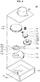
- FIG. 4 is an exploded perspective view of a valve actuator according to a first exemplary embodiment of the present disclosure
- FIG. 5 is a perspective view illustrating a coupling state of a gear assembly and a lift member illustrated in FIG. 4
- FIG. 6 is a bottom perspective view of the gear assembly and the lift member illustrated in FIG. 5 .
- FIGS. 7 and 8 are diagrams illustrating an actuation state of the valve actuator according to the first exemplary embodiment of the present disclosure.
- the gear assembly includes an input gear 131 coupled and/or connected to a rotational shaft of the motor 120 and receiving the driving force of the motor 120, an output gear 132 coupled to a valve output shaft 140 and transmitting rotational force of the input gear 131 to the valve output shaft 140, and at least one power transmission gear transmitting the rotational force of the input gear 131 to the output gear 132.
- the power transmission gear is constituted by first to third gears, but the number of power transmission gears may be appropriately changed.
- the input gear 131 includes a tooth portion 131a.
- a first gear 133 coupled to the input gear 131 includes a first tooth portion 133a physically directly coupled to the toot portion 131a of the input gear 131 and a second tooth portion 133b disposed below the first tooth portion 133a on an axis of the first gear 133.
- a first tooth portion 134a of a second gear 134 is physically directly coupled to the second tooth portion 133b of the first gear 133, and the second tooth portion 134b is positioned above the first tooth portion 134a on the axis of the second gear 134.
- a third gear 135 includes a first tooth portion 135a physically directly coupled to the second tooth portion 134b of the second gear 134, and a second tooth portion 135b positioned below the first tooth portion 135a on the axis of the third gear 135.
- a tooth portion 132a of the output gear 132 is physically directly coupled to the second tooth portion 135b of the third gear 135, and the output gear 132 is coupled to the valve output shaft 140.
- the tooth portion 132a of the output gear 132 may be formed in an arc shape.
- a selective power transmission unit for interrupting the rotation of the output gear 132 includes a lift member that moves the first gear upward and releasing the engagement of the first gear 133 and the second gear 134.
- the lift member 150 includes a body 150a coupled to the valve output shaft 140 above the output gear 132 and a lever 150b extended from the body 150a and having an end portion positioned below the first gear 131.
- a projection portion 132c is formed in the output gear 132, and a groove portion 150c into which the projection portion 132c of the output gear 132 is inserted is formed in the body 150a of the lift member 150.
- a guide groove 140a for guiding vertical movement of the lift member 150 is formed in the valve output shaft 140, and a guide portion 150d inserted into the guide groove 140a is formed in the body 150a of the lift member 150.
- an elastic member pressing the first gear 133 downward e.g., a coil spring 160 is positioned above the first gear 133.
- the projection portion 132c of the output gear 132 is positioned within the groove portion 150c provided in the body 150a of the lift member 150 within a normal actuation range of the valve actuator.
- the "normal actuation range of the valve actuator” means a state in which driving of the motor 120 is stopped and an initial state in which the motor 120 is driven in order to close the path by controlling the ball valve 10.
- the projection portion 132c of the output gear 132 deviates from the groove portion 150c provided in the body 150a of the lift member 150 and the lift member 150 moves upward while the projection portion 132c starts to deviate from the groove portion 150c provided in the body 150a of the lift member 150, as illustrated in FIGS. 7 and 8 .
- the lift member 150 moves by a mutual actuation of the guide groove 140a provided in the valve output shaft 140 and a guide portion 150d provided in the body 150a of the lift member 150.
- At least one of a friction pad 150e or a friction protrusion 150f may be provided at an end portion of the lever 150b, and at least one of the friction pad or the friction protrusion may be provided even on a lower surface of the first gear 133.
- FIG. 11 is a perspective view of a valve actuator according to a second exemplary embodiment of the present disclosure
- FIG. 12 is a diagram illustrating an actuation state of the valve actuator according to the second exemplary embodiment of the present disclosure.
- valve actuator since the remaining configurations except for the lift member are configured in the same or similar manner as the first exemplary embodiment, a detailed description thereof will be omitted.
- a lift member 150' includes a body 150'a coupled to a lateral portion of the output gear 132 and a lever 150'b extended from the body 150'a and having an end portion positioned below the first gear 133.
- the tooth portion 132a of the output gear 132 is spaced apart from the body 150'a of the lift member 150' within the normal actuation range of the valve actuator.
- the tooth portion 132a of the output gear 132 contacts the body 150'a of the lift member 150', and when the output gear 132 is continuously rotated, the lever 150'b is lifted upward while the body 150'a of the lift member 150' is transformed in an arrow direction.
- At least one of the friction pad or the friction protrusion may be provided at an end portion of the lever 150'b, and at least one of the friction pad or the friction protrusion may be provided even on the lower surface of the first gear 133, as described in the exemplary embodiment described above.
- the selective power transmission unit of the valve actuator includes the lift member and the engagement of the first gear and the second gear is thus released in the above exemplary embodiments, but it is also possible to brake the first gear not to be rotated instead of releasing the engagement of the first gear and the second gear.
- valve actuator according to a third exemplary embodiment of the present disclosure will be described with reference to FIGS. 13 to 15 .
- the valve actuator according to the third exemplary embodiment does not include the lift member according to the first and second exemplary embodiments described above, but includes the friction member provided in the output gear in order to brake the first gear by using the rotation of the output gear.
- the output gear 132 is coupled to the valve output shaft 140 to be vertically movable.
- the projection portion 132d may be formed on the lower surface of the output gear 132 and an inclination surface 110a at which the projection portion 132d is positioned may be formed in the case 110.
- the friction member such as a friction pad 132e, etc.
- the friction pad such as a friction pad, etc.
- the friction member may be provided in the output gear 132, and the fiction pad such as a friction pad, etc., may be provided even in the first gear 133 at a location facing the friction pad 132d of the output gear 132.
- the first gear 133 is braked by using the friction pad 132e of the output gear 132.
- the input gear 131 may have a safety rte of 3.0
- the first gear may have a safety rate of 1.8
- the second gear may have a safety rate of 1.6
- the third gear may have a safety rate of 1.1.
- the projection portion 132d of the output gear 132 is positioned on the inclination surface 110a of the case 110 within the normal actuation range of the valve actuator.
- the output gear 132 moves upward while the protrusion 132c moves along the inclination surface 110a, and as a result, the friction pad 132e of the output gear 132 is in close contact with the lower surface of the first gear 133 and the first gear 133 is thus braked.
- threads 140b which are engaged with each other may be formed in the output gear 132 and the valve output shaft 140.
- a thread 132f of the output gear 132 and a thread 140b of the valve output shaft 140 may not be engaged with each other within the normal actuation range of the valve actuator, and the output gear 132 may rotate together with the valve output shaft 140.
- the thread 132f of the output gear 132 and the thread 140b of the valve output shaft 140 may be formed with a predetermined height difference within the normal actuation range of the valve actuator.
- valve output shaft 140 is rotated and the path of the ball valve is thus closed, and then the driving force of the motor 120 is not transmitted to the valve output shaft 140 even though the driving of the motor 120 is not stopped, but the motor 120 is continuously driven.
- the motor and/or the gear assembly are/is prevented from being damaged due to the over-torque.
- valve actuator of the present disclosure uses the lift member or the friction member having a simple structure, the durability and the driving stability of the valve actuator are secured.
- valve actuator of the present disclosure need not include a separate electronic switch and a separate PCB for the motor stop signal, the instability of the electronic switch or the electronic sensor is removed, and the complexity and the material cost of the device are improved.
- valve actuator for controlling the ball valve provided in the air conditioner has been described, but the valve actuator according to the present disclosure may be used in a valve for controlling a path of gas or a fluid.
Landscapes
- Engineering & Computer Science (AREA)
- General Engineering & Computer Science (AREA)
- Mechanical Engineering (AREA)
- Electrically Driven Valve-Operating Means (AREA)
- Mechanically-Actuated Valves (AREA)
Abstract
Description
- The present disclosure relates to a valve actuator for automatically opening/closing a valve, and more particularly, to a valve actuator having an over-torque interruption function.
- Refrigerant is essentially used in an air conditioner which is one of the air conditioning devices, and Freon gas used as the refrigerant acts as a factor of global warming.
- Therefore, in recent years, refrigerant has been developed, which is not concerned with the global warming, and the newly developed refrigerant does not act as the factor of the global warming, but there is a risk of a fire in the case of refrigerant leakage due to an ignition propensity, and as a result, a valve actuator for automatically actuating a valve for interrupting leakage in the case of the refrigerant leakage has been developed.
- As a valve installed between an outdoor unit and an indoor unit of the air conditioner and preventing the refrigerant leakage, a ball valve is primarily used, and as illustrated in
FIG. 1 , aball valve 10 includes aball 11 with a path, apipe 12 into which theball 11 is inserted, astem 13 connected to thepipe 12, aseal member 14 installed in thestem 13, and astem fixation bolt 15. - A valve actuator for controlling the ball valve having such a configuration generally includes a motor and a gear assembly, and controls the valve by controlling rotation of the motor by using a sensor such as a limit switch, etc., or controlling the rotation of the motor by using a step motor.
- As an example,
Korean Patent Application No. 10-2007-0141333 - However, the valve actuator of the prior patent having the electronic limit switch has a problem in that sensors' peculiar instability in a harsh environment.
-
Korean Patent Application No, 10-2007-0141333 - The present disclosure provides a valve actuator capable of securing durability and driving stability.
- The present disclosure also provides a valve actuator removing instability of an electronic sensor.
- The present disclosure also provides a valve actuator which need not include a separate PCB for a motor stop signal.
- The objects of the present disclosure are not limited to the above-mentioned objects, and other objects and advantages of the present disclosure that are not mentioned can be understood by the following description, and will be more clearly understood by embodiments of the present disclosure.
- Further, it will be readily appreciated that the objects and advantages of the present disclosure can be realized by means and combinations shown in the claims.
- A valve actuator according to an exemplary embodiment of the present disclosure includes: a motor; a gear assembly including an input gear rotated by driving force of the motor, an output gear receiving rotational force of the input gear, and at least one power transmission gear transmitting the rotational force of the input gear to the output gear; a valve output shaft coupled to the output gear and configured to be actuated to close a valve; and a selective power transmission unit for interrupting rotation of the output gear after the output gear is rotated at a predetermined angle by the rotational force of the input gear, and the selective power transmission unit includes a lift member releasing meshing of the first gear and the second gear by moving the first gear to an upper side after the output gear is rotated at the predetermined angle or a friction member provided at the output gear so as to brake the rotation of the first gear by contacting the first gear after the output gear is rotated at the predetermined angle.
- The valve actuator may further comprise a case in which the gear assembly is installed.
- The motor may be installed on or outside the case.
- The power transmission gear may include a first gear coupled to the input gear, a second gear coupled to the first gear, and a third gear coupled to each of the second gear and the output gear.
- The selective power transmission unit may include a lift member configured to disengage the first gear from the second gear by the lift member moving and thus pushing the first gear away from the second gear due to interference with a portion of the output gear after the output gear is rotated at the predetermined angle.
- The lift member may include a body connected to the valve output shaft on or above an upper side of the output gear and a lever extended from the body and having an end portion positioned on or below a lower side of the first gear.
- A projection may be formed on one of the output gear and th body, and a groove portion into which the projection is inserted may be formed at the other one of the output gear and the body. A guide groove guiding vertical movement of the body may be formed at one of the valve output shaft and the body, and a guide portion inserted into the guide groove may be formed at the other one of the valve output shaft and the body.
- An elastic member pressing the first gear downward may be positioned at an upper side of the first gear.
- A friction pad providing frictional force to the first gear may be formed at the lever or the first gear.
- A friction protrusion providing frictional force to the first gear may be formed at the lever or the first gear.
- The lift member may include a body fixed to a lateral portion of the output gear, and a lever extended from the body and having an end portion positioned on or below a lower side of the first gear.
- When the output gear contacts the body, the body may be configured to be deformed so that the lever contacts and pushes the first gear away from the second gear.
- The selective power transmission unit includes a friction member provided at the output gear so as to brake the rotation of the first gear by contact with the first gear after the output gear is rotated at the predetermined angle.
- The output gear is installed at the valve output shaft to be vertically movable.
- A projection portion may be formed at one of the output gear and the case, and an inclined surface on which the projection portion is positioned may be formed at the other one of the output gear and the case.
- Threads, which are capalbe of being engaged with each other, may be formed at the output gear and the valve output shaft.
- According to the present disclosure, driving force of a motor is transmitted to a valve output shaft through a gear assembly and a valve is closed, and then the driving force of the motor is not transmitted to the valve output shaft by the selective power transmission unit to prevent damage to the gear assembly and/or the motor due to over-torque and apply a motor of a type in which an RPM control is inaccurate.
- In addition, since the electronic sensor is not used, the instability of the electronic sensor can be removed, and a separate PCB for a motor stop signal need not be provided, thereby increasing durability, and improving complexity and material cost.
- In addition to the above-described effects, the specific effects of the present disclosure will be described below together while describing the specific matters for the present disclosure.
-
-
FIG. 1 is an exploded perspective view illustrating a configuration of a general ball valve. -
FIG. 2 is a diagram illustrating a coupling state of a valve actuator and a ball valve according to an exemplary embodiment of the present disclosure. -
FIG. 3 is an exterior perspective view of the valve actuator illustrated inFIG. 2 . -
FIG. 4 is an exploded perspective view of a valve actuator according to a first exemplary embodiment of the present disclosure. -
FIG. 5 is a perspective view illustrating a coupling state of a gear assembly and a lift member illustrated inFIG. 4 . -
FIG. 6 is a bottom perspective view of the gear assembly and the lift member illustrated inFIG. 5 . -
FIGS. 7 and 8 are diagrams illustrating an actuation state of the valve actuator according to the first exemplary embodiment of the present disclosure. -
FIGS. 9 and 10 are perspective views of a main part illustrating a modified exemplary embodiment of the lift member provided in the valve actuator according to the first exemplary embodiment of the present disclosure. -
FIG. 11 is a perspective view of a valve actuator according to a second exemplary embodiment of the present disclosure. -
FIG. 12 is a diagram illustrating an actuation state of the valve actuator according to the second exemplary embodiment of the present disclosure. -
FIG. 13 is a perspective view of a valve actuator according to a third exemplary embodiment of the present disclosure. -
FIGS. 14 and15 are diagrams illustrating a configuration of a main part for moving an output gear in a vertical direction in the valve actuator according to the third exemplary embodiment of the present disclosure. - The present disclosure will be described more fully hereinafter with reference to the accompanying drawings, in which exemplary embodiments of the invention are shown. The present disclosure can be realized in various different forms, and is not limited to the exemplary embodiments described herein.
- A part irrelevant to the description will be omitted to clearly describe the present disclosure, and the same elements will be designated by the same reference numerals throughout the specification. Further, some exemplary embodiments of the present disclosure will be described in detail with reference to illustrative drawings.
- When reference numerals refer to components of each drawing, although the same components are illustrated in different drawings, the same components are denoted by the same reference numerals as possible. Further, in describing the present disclosure, a detailed description of known related configurations and functions may be omitted to avoid unnecessarily obscuring the subject matter of the present disclosure.
- In describing the component of the present disclosure, when it is disclosed that any component is "connected", "coupled", or "linked" to other components, it should be understood that another component may be "interposed" between respective components or the respective components may be "connected", "coupled", or "linked" through another component.
-
FIG. 2 is a diagram illustrating a coupling state of a valve actuator and a ball valve according to an exemplary embodiment of the present disclosure andFIG. 3 is an exterior perspective view of the valve actuator illustrated inFIG. 2 . - As illustrated, in order to install the
valve actuator 100 in theball valve 10, aplate 20 may be installed above theball valve 10, and thevalve actuator 100 may be coupled to theplate 20. - The
plate 20 may be fixed to an upper end of theball valve 10 by a fastening member such as a fastening screw, etc., and thevalve actuator 100 may be fixed to theplate 20 by the fastening member such as the fastening screw, etc. - The
valve actuator 100 includes acase 110. - The
case 110 provides a space in which amotor 120 and a gear assembly provided in thevalve actuator 100 are installed, themotor 120 is installed on an upper surface of thecase 110 outside thecase 110, and the gear assembly is disposed in an internal space of thecase 110. - The
motor 120 may be a motor of a type in which RPM control is accurate. However, this is not required, and themotor 120 may be a motor of a type in which the RPM control is inaccurate. That is, since the valve actuator according to the exemplary embodiment of the present disclosure may selectively transmit power by a mechanical structure, damage to the gear assembly may be prevented and the ball valve may be accurately controlled while using the motor of the type in which the RPM control is inaccurate. -
FIG. 4 is an exploded perspective view of a valve actuator according to a first exemplary embodiment of the present disclosure,FIG. 5 is a perspective view illustrating a coupling state of a gear assembly and a lift member illustrated inFIG. 4 , andFIG. 6 is a bottom perspective view of the gear assembly and the lift member illustrated inFIG. 5 . - In addition,
FIGS. 7 and 8 are diagrams illustrating an actuation state of the valve actuator according to the first exemplary embodiment of the present disclosure. - As illustrated, the gear assembly includes an
input gear 131 coupled and/or connected to a rotational shaft of themotor 120 and receiving the driving force of themotor 120, anoutput gear 132 coupled to avalve output shaft 140 and transmitting rotational force of theinput gear 131 to thevalve output shaft 140, and at least one power transmission gear transmitting the rotational force of theinput gear 131 to theoutput gear 132. - Hereinafter, it will be described as an example that the power transmission gear is constituted by first to third gears, but the number of power transmission gears may be appropriately changed.
- In addition, in the exemplary embodiment, while the rotational force of the input gear is transmitted to the output gear through the power transmission gear, a speed is reduced by the gear assembly or the power transmission gear.
- The
input gear 131 includes atooth portion 131a. - A
first gear 133 coupled to theinput gear 131 includes afirst tooth portion 133a physically directly coupled to thetoot portion 131a of theinput gear 131 and asecond tooth portion 133b disposed below thefirst tooth portion 133a on an axis of thefirst gear 133. - A
first tooth portion 134a of asecond gear 134 is physically directly coupled to thesecond tooth portion 133b of thefirst gear 133, and thesecond tooth portion 134b is positioned above thefirst tooth portion 134a on the axis of thesecond gear 134. - In addition, a
third gear 135 includes afirst tooth portion 135a physically directly coupled to thesecond tooth portion 134b of thesecond gear 134, and asecond tooth portion 135b positioned below thefirst tooth portion 135a on the axis of thethird gear 135. - In addition, a
tooth portion 132a of theoutput gear 132 is physically directly coupled to thesecond tooth portion 135b of thethird gear 135, and theoutput gear 132 is coupled to thevalve output shaft 140. - The
tooth portion 132a of theoutput gear 132 may be formed in an arc shape. - In the exemplary embodiment, after the
output gear 132 is rotated at a predetermined angle (e.g., 90 degrees) by the rotational force of theinput gear 131, a selective power transmission unit for interrupting the rotation of theoutput gear 132 includes a lift member that moves the first gear upward and releasing the engagement of thefirst gear 133 and thesecond gear 134. - In the exemplary embodiment, the
lift member 150 includes abody 150a coupled to thevalve output shaft 140 above theoutput gear 132 and alever 150b extended from thebody 150a and having an end portion positioned below thefirst gear 131. - In addition, in order to move the
lift member 150 in the vertical direction, aprojection portion 132c is formed in theoutput gear 132, and agroove portion 150c into which theprojection portion 132c of theoutput gear 132 is inserted is formed in thebody 150a of thelift member 150. - In addition, a
guide groove 140a for guiding vertical movement of thelift member 150 is formed in thevalve output shaft 140, and aguide portion 150d inserted into theguide groove 140a is formed in thebody 150a of thelift member 150. - In addition, an elastic member pressing the
first gear 133 downward, e.g., acoil spring 160 is positioned above thefirst gear 133. - Accordingly, in a state in which the gear assembly 130 and the
lift member 150 are coupled as illustrated inFIGS. 5 and 6 , theprojection portion 132c of theoutput gear 132 is positioned within thegroove portion 150c provided in thebody 150a of thelift member 150 within a normal actuation range of the valve actuator. - In addition, in this state, the
body 150c of thelift member 150 is seated on theoutput gear 132. - Here, the "normal actuation range of the valve actuator" means a state in which driving of the
motor 120 is stopped and an initial state in which themotor 120 is driven in order to close the path by controlling theball valve 10. - However, when the
motor 120 is driven in order to close a path by controlling theball valve 10, theoutput gear 132 is rotated. - In this case, since the
projection portion 132c of theoutput gear 132 is positioned within thegroove 150c provided in thebody 150a of thelift member 150, only theoutput gear 132 is rotated in a state in which thelift member 150 is stopped. - However, after the
output gear 132 is rotated at a predetermined angle, e.g., 90 degrees and the path of the ball valve is thus closed, theprojection portion 132c of theoutput gear 132 deviates from thegroove portion 150c provided in thebody 150a of thelift member 150 and thelift member 150 moves upward while theprojection portion 132c starts to deviate from thegroove portion 150c provided in thebody 150a of thelift member 150, as illustrated inFIGS. 7 and 8 . - In this case, the
lift member 150 moves by a mutual actuation of theguide groove 140a provided in thevalve output shaft 140 and aguide portion 150d provided in thebody 150a of thelift member 150. - Accordingly, since the
lever 150b provided in thelift member 150 moves thefirst gear 133 upward, the engagement of thesecond tooth portion 133b of thefirst gear 133a and thefirst tooth portion 134a of thesecond gear 134 is released, and as a result, the rotational force of theinput gear 131 is not transmitted to theoutput gear 132. - Meanwhile, in order to more effectively achieve upward movement of the
first gear 133, at least one of afriction pad 150e or afriction protrusion 150f may be provided at an end portion of thelever 150b, and at least one of the friction pad or the friction protrusion may be provided even on a lower surface of thefirst gear 133. - Hereinafter, other exemplary embodiments will be described.
-
FIG. 11 is a perspective view of a valve actuator according to a second exemplary embodiment of the present disclosure andFIG. 12 is a diagram illustrating an actuation state of the valve actuator according to the second exemplary embodiment of the present disclosure. - In the valve actuator according to the exemplary embodiment, since the remaining configurations except for the lift member are configured in the same or similar manner as the first exemplary embodiment, a detailed description thereof will be omitted.
- In the exemplary embodiment, a lift member 150' includes a body 150'a coupled to a lateral portion of the
output gear 132 and a lever 150'b extended from the body 150'a and having an end portion positioned below thefirst gear 133. - Accordingly, in a state in which the gear assembly 130 and the lift member 150' are coupled, the
tooth portion 132a of theoutput gear 132 is spaced apart from the body 150'a of the lift member 150' within the normal actuation range of the valve actuator. - However, when the
motor 120 is driven in order to close a path by controlling theball valve 10, theoutput gear 132 is rotated. - In addition, after the
output gear 132 is rotated at a predetermined angle, i.e., 90 degrees and the path of the ball valve is thus closed, thetooth portion 132a of theoutput gear 132 contacts the body 150'a of the lift member 150', and when theoutput gear 132 is continuously rotated, the lever 150'b is lifted upward while the body 150'a of the lift member 150' is transformed in an arrow direction. - Accordingly, since the
first gear 133 moved upward by the lever 150'b provided in the lift member 150', the engagement of thesecond tooth portion 133b of thefirst gear 133a and thefirst tooth portion 134a of thesecond gear 134 is released, and as a result, the rotational force of theinput gear 131 is not transmitted to theoutput gear 132. - Meanwhile, in order to more effectively achieve upward movement of the
first gear 133, at least one of the friction pad or the friction protrusion may be provided at an end portion of the lever 150'b, and at least one of the friction pad or the friction protrusion may be provided even on the lower surface of thefirst gear 133, as described in the exemplary embodiment described above. - It is described as an example that the selective power transmission unit of the valve actuator includes the lift member and the engagement of the first gear and the second gear is thus released in the above exemplary embodiments, but it is also possible to brake the first gear not to be rotated instead of releasing the engagement of the first gear and the second gear.
- Hereinafter, a valve actuator according to a third exemplary embodiment of the present disclosure will be described with reference to
FIGS. 13 to 15 . - The valve actuator according to the third exemplary embodiment does not include the lift member according to the first and second exemplary embodiments described above, but includes the friction member provided in the output gear in order to brake the first gear by using the rotation of the output gear.
- In the exemplary embodiment, the
output gear 132 is coupled to thevalve output shaft 140 to be vertically movable. - To this end, the
projection portion 132d may be formed on the lower surface of theoutput gear 132 and aninclination surface 110a at which theprojection portion 132d is positioned may be formed in thecase 110. - In addition, the friction member such as a
friction pad 132e, etc., may be provided in theoutput gear 132, and the fiction pad such as a friction pad, etc., may be provided even in thefirst gear 133 at a location facing thefriction pad 132d of theoutput gear 132. - In the exemplary embodiment, since a safety rte of the first gear among the first to third gears is the highest, the
first gear 133 is braked by using thefriction pad 132e of theoutput gear 132. - For example, the
input gear 131 may have a safety rte of 3.0, the first gear may have a safety rate of 1.8, the second gear may have a safety rate of 1.6, and the third gear may have a safety rate of 1.1. - According to such a configuration, the
projection portion 132d of theoutput gear 132 is positioned on theinclination surface 110a of thecase 110 within the normal actuation range of the valve actuator. - However, when the
motor 120 is driven and theoutput gear 132 is thus rotated, the path of the valve is closed, and even then, when themotor 120 is continuously driven, theprotrusion 132c of theoutput gear 132 moves along theinclination surface 110a, and then deviates from theinclination surface 110a. - Accordingly, the
output gear 132 moves upward while theprotrusion 132c moves along theinclination surface 110a, and as a result, thefriction pad 132e of theoutput gear 132 is in close contact with the lower surface of thefirst gear 133 and thefirst gear 133 is thus braked. - Unlike this, as illustrated in
FIG. 15 ,threads 140b which are engaged with each other may be formed in theoutput gear 132 and thevalve output shaft 140. - In this case, a
thread 132f of theoutput gear 132 and athread 140b of thevalve output shaft 140 may not be engaged with each other within the normal actuation range of the valve actuator, and theoutput gear 132 may rotate together with thevalve output shaft 140. - Accordingly, the
thread 132f of theoutput gear 132 and thethread 140b of thevalve output shaft 140 may be formed with a predetermined height difference within the normal actuation range of the valve actuator. - However, when the
motor 120 is driven and theoutput gear 132 is thus rotated, the path of the ball valve is closed, and even then, when themotor 120 is continuously driven, thethread 132f of theoutput gear 132 and thethread 140b of the valve output shaft are engaged with each other, and as a result, thefriction pad 132e of theoutput gear 132 is in close contact with the lower surface of thefirst gear 133 while theoutput gear 132 moves upward, and thefirst gear 133 is thus braked. - Accordingly, the
valve output shaft 140 is rotated and the path of the ball valve is thus closed, and then the driving force of themotor 120 is not transmitted to thevalve output shaft 140 even though the driving of themotor 120 is not stopped, but themotor 120 is continuously driven. - Accordingly, the motor and/or the gear assembly are/is prevented from being damaged due to the over-torque.
- In addition, since the valve actuator of the present disclosure uses the lift member or the friction member having a simple structure, the durability and the driving stability of the valve actuator are secured.
- In addition, since the valve actuator of the present disclosure need not include a separate electronic switch and a separate PCB for the motor stop signal, the instability of the electronic switch or the electronic sensor is removed, and the complexity and the material cost of the device are improved.
- Hereinabove, the valve actuator for controlling the ball valve provided in the air conditioner has been described, but the valve actuator according to the present disclosure may be used in a valve for controlling a path of gas or a fluid.
Claims (15)
- A valve actuator comprising:a motor (120);a gear assembly including an input gear (131) rotated by driving force of the motor (120), an output gear (132) receiving rotational force of the input gear (131), and at least one power transmission gear transmitting the rotational force of the input gear (131) to the output gear (132);a valve output shaft (140) coupled to the output gear (132) and configured to be actuated to close a valve (10); anda selective power transmission unit for interrupting rotation of the output gear (132) after the output gear (132) is rotated at a predetermined angle by the rotational force of the input gear (131).
- The valve actuator of claim 1, further comprising:
a case (110) in which the gear assembly is installed. - The valve actuator of claim 2, wherein the motor (120) is installed outside or on the case (110).
- The valve actuator of claim 2 or 3, wherein the power transmission gear includes a first gear (133) coupled to the input gear (131), a second gear (134) coupled to the first gear (133), and a third gear (135) coupled to each of the second gear (134) and the output gear (132).
- The valve actuator of claim 4, wherein the selective power transmission unit includes a lift member (150 or 150') configured to disengage the first gear (133) from the second gear (134) by the lift member (150, 150') moving and thus pushing the first gear (133) away from the second gear (134) due to interference with a portion of the output gear (132) after the output gear (132) is rotated at the predetermined angle.
- The valve actuator of claim 5, wherein the lift member (150) includes a body (150a) connected to the valve output shaft (140) on or above an upper side of the output gear (132), and a lever (150b) extended from the body (150a) and having an end portion positioned on or below a lower side of the first gear (133).
- The valve actuator of claim 6, wherein a projection (132c) is formed on one of the output gear (132) and the body (150a) and a groove portion (150c) into which the projection (132c) is inserted is formed at the one one of the output gear (132) and the body (150a), and
a guide groove (140a) guiding vertical movement of the body (150a) is formed at one of the valve output shaft (140) and the body (150a), and a guide portion (150d) inserted into the guide groove (140a) is formed at the other one of the valve output shaft (140) and the body (150a). - The valve actuator of claim 6 or 7, wherein an elastic member (160) pressing the first gear (133) downward is positioned at an upper side of the first gear (133).
- The valve actuator of any one of claims 6 to 8, wherein a friction pad (150e) providing frictional force to the first gear (133) is formed at the lever (150b) or the first gear (133).
- The valve actuator of any one of claims 6 to 8, wherein a friction protrusion (150f) providing frictional force to the first gear (133) is formed at the lever (150b) or the first gear (133).
- The valve actuator of claim 5, wherein the lift member (150') includes a body (150'a) fixed to a lateral portion of the output gear (132) and a lever (150'b) extended from the body (150'a) and having an end portion positioned on or below a lower side of the first gear (133).
- The valve actuator of claim 11, wherein when the output gear (132) contacts the body (150'a), the body (150'a) is deformed so that the lever (150'b) contacts and pushes the first gear (133) away from the second gear (134).
- The valve actuator of claim 4, wherein the selective power transmission unit includes a friction member (132e) provided at the output gear (132) so as to brake the rotation of the first gear (133) by contact with the first gear (133) after the output gear (132) is rotated at the predetermined angle.
- The valve actuator of claim 13, wherein the output gear (132) is installed at the valve output shaft (140) to be vertically movable,
wherein a projection portion (132d) is formed at one of the output gear (132) and the case (110), and an inclined surface (110a) on which the projection portion (132d) is positioned is formed at the other one of the outut gear (132) and the case (110). - The valve actuator of claim 14, wherein both of the output gear (132) and the valve output shaft (140) comprises threads (132f, 140b) which are configured to engaged with each other after the output gear (132) is rotated at the predetermined angle.
Applications Claiming Priority (1)
| Application Number | Priority Date | Filing Date | Title |
|---|---|---|---|
| KR1020210114406A KR102625650B1 (en) | 2021-08-30 | 2021-08-30 | Valve actuator |
Publications (2)
| Publication Number | Publication Date |
|---|---|
| EP4141300A1 true EP4141300A1 (en) | 2023-03-01 |
| EP4141300B1 EP4141300B1 (en) | 2025-07-02 |
Family
ID=82851516
Family Applications (1)
| Application Number | Title | Priority Date | Filing Date |
|---|---|---|---|
| EP22189401.7A Active EP4141300B1 (en) | 2021-08-30 | 2022-08-09 | Valve actuator |
Country Status (3)
| Country | Link |
|---|---|
| US (1) | US12066112B2 (en) |
| EP (1) | EP4141300B1 (en) |
| KR (1) | KR102625650B1 (en) |
Families Citing this family (2)
| Publication number | Priority date | Publication date | Assignee | Title |
|---|---|---|---|---|
| CN114033887A (en) * | 2021-10-29 | 2022-02-11 | 宁波卡伦特电器有限公司 | An electronically controlled actuator, an exhaust gas treatment system and a vehicle |
| KR102735407B1 (en) * | 2023-07-05 | 2024-11-27 | 주식회사 에스 씨디 | Valve actuator for electric vehicle integrated thermal management module |
Citations (2)
| Publication number | Priority date | Publication date | Assignee | Title |
|---|---|---|---|---|
| KR20090073402A (en) * | 2007-12-31 | 2009-07-03 | 주식회사 밸콘 | Electric ball valve |
| US10527136B2 (en) * | 2015-12-29 | 2020-01-07 | Sogefi Air & Cooling (Societe Par Actions Simplifiee) | One-way device for transmitting movement by toothed elements and kinematic link |
Family Cites Families (7)
| Publication number | Priority date | Publication date | Assignee | Title |
|---|---|---|---|---|
| US2761331A (en) * | 1952-05-17 | 1956-09-04 | Gen Controls Co | Load operating device with automatic declutching mechanism |
| US4261224A (en) * | 1978-10-17 | 1981-04-14 | Anchor/Darling Industries, Inc. | Valve actuator |
| US6073907A (en) * | 1997-11-07 | 2000-06-13 | Erie Manufacturing Company | Removable and interchangeable valve actuator system |
| IT1320448B1 (en) * | 2000-06-23 | 2003-11-26 | Elbi Int Spa | ELECTROMECHANICAL ACTUATOR DEVICE. |
| GB2404717B (en) * | 2003-07-17 | 2005-12-21 | Rotork Controls | Drive mechanisms for valve actuators |
| CH708995B1 (en) * | 2004-03-19 | 2015-06-30 | Belimo Holding Ag | Reduction gear of an electrically operated actuator. |
| KR200458179Y1 (en) * | 2008-09-26 | 2012-01-25 | 주식회사 노비타 | Driving device of electric ball valve |
-
2021
- 2021-08-30 KR KR1020210114406A patent/KR102625650B1/en active Active
-
2022
- 2022-07-21 US US17/870,337 patent/US12066112B2/en active Active
- 2022-08-09 EP EP22189401.7A patent/EP4141300B1/en active Active
Patent Citations (2)
| Publication number | Priority date | Publication date | Assignee | Title |
|---|---|---|---|---|
| KR20090073402A (en) * | 2007-12-31 | 2009-07-03 | 주식회사 밸콘 | Electric ball valve |
| US10527136B2 (en) * | 2015-12-29 | 2020-01-07 | Sogefi Air & Cooling (Societe Par Actions Simplifiee) | One-way device for transmitting movement by toothed elements and kinematic link |
Also Published As
| Publication number | Publication date |
|---|---|
| US20230067855A1 (en) | 2023-03-02 |
| KR102625650B1 (en) | 2024-01-17 |
| KR20230032051A (en) | 2023-03-07 |
| US12066112B2 (en) | 2024-08-20 |
| EP4141300B1 (en) | 2025-07-02 |
Similar Documents
| Publication | Publication Date | Title |
|---|---|---|
| EP4141300A1 (en) | Valve actuator | |
| US5429090A (en) | Fail safe throttle positioning system | |
| US5490660A (en) | Manual device for valve | |
| EP3100892A1 (en) | Shift device for vehicle | |
| JP5150319B2 (en) | Valve actuator | |
| WO2004001262A1 (en) | Actuator for valve | |
| KR200458179Y1 (en) | Driving device of electric ball valve | |
| EP1033496B1 (en) | Fluid-powered actuator for a valve | |
| EP0990782B1 (en) | Accelerator pedal mechanism for vehicle | |
| JP3932322B2 (en) | Rotary joint | |
| EP2987046A1 (en) | Bidirectional pedal assembly | |
| KR102054374B1 (en) | Swing door opening and closing device for car | |
| CN87104170A (en) | The automatic clutch control system of pin with lock | |
| US11173881B2 (en) | Disc brake device | |
| EP0250220B1 (en) | Throttle body control arrangement | |
| EP4137729A1 (en) | Valve actuator | |
| EP4137728A1 (en) | Valve actuator | |
| JP4819450B2 (en) | Electric actuator | |
| JP2005098178A (en) | Throttle valve control device | |
| EP2574828B1 (en) | Shifter assembly for providing mechanical and electronic actuation to a transmission of a vehicle and a method of operating the shifter assembly | |
| KR20020084210A (en) | Electromotive clutch disc | |
| JP4358611B2 (en) | Emergency shut-off valve | |
| JP4237327B2 (en) | Torque switch | |
| KR102835917B1 (en) | Valve drive device and valve assembly having the same | |
| JP5162425B2 (en) | Fluid controller |
Legal Events
| Date | Code | Title | Description |
|---|---|---|---|
| PUAI | Public reference made under article 153(3) epc to a published international application that has entered the european phase |
Free format text: ORIGINAL CODE: 0009012 |
|
| STAA | Information on the status of an ep patent application or granted ep patent |
Free format text: STATUS: REQUEST FOR EXAMINATION WAS MADE |
|
| 17P | Request for examination filed |
Effective date: 20220909 |
|
| AK | Designated contracting states |
Kind code of ref document: A1 Designated state(s): AL AT BE BG CH CY CZ DE DK EE ES FI FR GB GR HR HU IE IS IT LI LT LU LV MC MK MT NL NO PL PT RO RS SE SI SK SM TR |
|
| RBV | Designated contracting states (corrected) |
Designated state(s): AL AT BE BG CH CY CZ DE DK EE ES FI FR GB GR HR HU IE IS IT LI LT LU LV MC MK MT NL NO PL PT RO RS SE SI SK SM TR |
|
| GRAP | Despatch of communication of intention to grant a patent |
Free format text: ORIGINAL CODE: EPIDOSNIGR1 |
|
| STAA | Information on the status of an ep patent application or granted ep patent |
Free format text: STATUS: GRANT OF PATENT IS INTENDED |
|
| INTG | Intention to grant announced |
Effective date: 20250220 |
|
| GRAS | Grant fee paid |
Free format text: ORIGINAL CODE: EPIDOSNIGR3 |
|
| GRAA | (expected) grant |
Free format text: ORIGINAL CODE: 0009210 |
|
| STAA | Information on the status of an ep patent application or granted ep patent |
Free format text: STATUS: THE PATENT HAS BEEN GRANTED |
|
| AK | Designated contracting states |
Kind code of ref document: B1 Designated state(s): AL AT BE BG CH CY CZ DE DK EE ES FI FR GB GR HR HU IE IS IT LI LT LU LV MC MK MT NL NO PL PT RO RS SE SI SK SM TR |
|
| REG | Reference to a national code |
Ref country code: GB Ref legal event code: FG4D |
|
| REG | Reference to a national code |
Ref country code: CH Ref legal event code: EP |
|
| REG | Reference to a national code |
Ref country code: DE Ref legal event code: R096 Ref document number: 602022016747 Country of ref document: DE |
|
| REG | Reference to a national code |
Ref country code: IE Ref legal event code: FG4D |
|
| PGFP | Annual fee paid to national office [announced via postgrant information from national office to epo] |
Ref country code: DE Payment date: 20250805 Year of fee payment: 4 |
|
| PGFP | Annual fee paid to national office [announced via postgrant information from national office to epo] |
Ref country code: AT Payment date: 20251020 Year of fee payment: 4 |
|
| REG | Reference to a national code |
Ref country code: NL Ref legal event code: MP Effective date: 20250702 |
|
| PG25 | Lapsed in a contracting state [announced via postgrant information from national office to epo] |
Ref country code: PT Free format text: LAPSE BECAUSE OF FAILURE TO SUBMIT A TRANSLATION OF THE DESCRIPTION OR TO PAY THE FEE WITHIN THE PRESCRIBED TIME-LIMIT Effective date: 20251103 |
|
| PG25 | Lapsed in a contracting state [announced via postgrant information from national office to epo] |
Ref country code: NL Free format text: LAPSE BECAUSE OF FAILURE TO SUBMIT A TRANSLATION OF THE DESCRIPTION OR TO PAY THE FEE WITHIN THE PRESCRIBED TIME-LIMIT Effective date: 20250702 |
|
| REG | Reference to a national code |
Ref country code: AT Ref legal event code: MK05 Ref document number: 1809558 Country of ref document: AT Kind code of ref document: T Effective date: 20250702 |
|
| PG25 | Lapsed in a contracting state [announced via postgrant information from national office to epo] |
Ref country code: IS Free format text: LAPSE BECAUSE OF FAILURE TO SUBMIT A TRANSLATION OF THE DESCRIPTION OR TO PAY THE FEE WITHIN THE PRESCRIBED TIME-LIMIT Effective date: 20251102 |
|
| PG25 | Lapsed in a contracting state [announced via postgrant information from national office to epo] |
Ref country code: NO Free format text: LAPSE BECAUSE OF FAILURE TO SUBMIT A TRANSLATION OF THE DESCRIPTION OR TO PAY THE FEE WITHIN THE PRESCRIBED TIME-LIMIT Effective date: 20251002 |
|
| REG | Reference to a national code |
Ref country code: LT Ref legal event code: MG9D |
|
| PG25 | Lapsed in a contracting state [announced via postgrant information from national office to epo] |
Ref country code: AT Free format text: LAPSE BECAUSE OF FAILURE TO SUBMIT A TRANSLATION OF THE DESCRIPTION OR TO PAY THE FEE WITHIN THE PRESCRIBED TIME-LIMIT Effective date: 20250702 |
|
| PG25 | Lapsed in a contracting state [announced via postgrant information from national office to epo] |
Ref country code: FI Free format text: LAPSE BECAUSE OF FAILURE TO SUBMIT A TRANSLATION OF THE DESCRIPTION OR TO PAY THE FEE WITHIN THE PRESCRIBED TIME-LIMIT Effective date: 20250702 |
|
| PG25 | Lapsed in a contracting state [announced via postgrant information from national office to epo] |
Ref country code: HR Free format text: LAPSE BECAUSE OF FAILURE TO SUBMIT A TRANSLATION OF THE DESCRIPTION OR TO PAY THE FEE WITHIN THE PRESCRIBED TIME-LIMIT Effective date: 20250702 |
|
| PG25 | Lapsed in a contracting state [announced via postgrant information from national office to epo] |
Ref country code: GR Free format text: LAPSE BECAUSE OF FAILURE TO SUBMIT A TRANSLATION OF THE DESCRIPTION OR TO PAY THE FEE WITHIN THE PRESCRIBED TIME-LIMIT Effective date: 20251003 |
|
| PG25 | Lapsed in a contracting state [announced via postgrant information from national office to epo] |
Ref country code: CZ Free format text: LAPSE BECAUSE OF FAILURE TO SUBMIT A TRANSLATION OF THE DESCRIPTION OR TO PAY THE FEE WITHIN THE PRESCRIBED TIME-LIMIT Effective date: 20250702 Ref country code: SE Free format text: LAPSE BECAUSE OF FAILURE TO SUBMIT A TRANSLATION OF THE DESCRIPTION OR TO PAY THE FEE WITHIN THE PRESCRIBED TIME-LIMIT Effective date: 20250702 |
|
| PG25 | Lapsed in a contracting state [announced via postgrant information from national office to epo] |
Ref country code: LV Free format text: LAPSE BECAUSE OF FAILURE TO SUBMIT A TRANSLATION OF THE DESCRIPTION OR TO PAY THE FEE WITHIN THE PRESCRIBED TIME-LIMIT Effective date: 20250702 |
|
| PG25 | Lapsed in a contracting state [announced via postgrant information from national office to epo] |
Ref country code: PL Free format text: LAPSE BECAUSE OF FAILURE TO SUBMIT A TRANSLATION OF THE DESCRIPTION OR TO PAY THE FEE WITHIN THE PRESCRIBED TIME-LIMIT Effective date: 20250702 Ref country code: BG Free format text: LAPSE BECAUSE OF FAILURE TO SUBMIT A TRANSLATION OF THE DESCRIPTION OR TO PAY THE FEE WITHIN THE PRESCRIBED TIME-LIMIT Effective date: 20250702 |
|
| PG25 | Lapsed in a contracting state [announced via postgrant information from national office to epo] |
Ref country code: RS Free format text: LAPSE BECAUSE OF FAILURE TO SUBMIT A TRANSLATION OF THE DESCRIPTION OR TO PAY THE FEE WITHIN THE PRESCRIBED TIME-LIMIT Effective date: 20251002 |
|
| PG25 | Lapsed in a contracting state [announced via postgrant information from national office to epo] |
Ref country code: ES Free format text: LAPSE BECAUSE OF FAILURE TO SUBMIT A TRANSLATION OF THE DESCRIPTION OR TO PAY THE FEE WITHIN THE PRESCRIBED TIME-LIMIT Effective date: 20250702 |
|
| PG25 | Lapsed in a contracting state [announced via postgrant information from national office to epo] |
Ref country code: RO Free format text: LAPSE BECAUSE OF FAILURE TO SUBMIT A TRANSLATION OF THE DESCRIPTION OR TO PAY THE FEE WITHIN THE PRESCRIBED TIME-LIMIT Effective date: 20250702 |
|
| REG | Reference to a national code |
Ref country code: CH Ref legal event code: H13 Free format text: ST27 STATUS EVENT CODE: U-0-0-H10-H13 (AS PROVIDED BY THE NATIONAL OFFICE) Effective date: 20260324 |
|
| PG25 | Lapsed in a contracting state [announced via postgrant information from national office to epo] |
Ref country code: SM Free format text: LAPSE BECAUSE OF FAILURE TO SUBMIT A TRANSLATION OF THE DESCRIPTION OR TO PAY THE FEE WITHIN THE PRESCRIBED TIME-LIMIT Effective date: 20250702 |
|
| PG25 | Lapsed in a contracting state [announced via postgrant information from national office to epo] |
Ref country code: DK Free format text: LAPSE BECAUSE OF FAILURE TO SUBMIT A TRANSLATION OF THE DESCRIPTION OR TO PAY THE FEE WITHIN THE PRESCRIBED TIME-LIMIT Effective date: 20250702 |
|
| PG25 | Lapsed in a contracting state [announced via postgrant information from national office to epo] |
Ref country code: IT Free format text: LAPSE BECAUSE OF FAILURE TO SUBMIT A TRANSLATION OF THE DESCRIPTION OR TO PAY THE FEE WITHIN THE PRESCRIBED TIME-LIMIT Effective date: 20250702 Ref country code: LU Free format text: LAPSE BECAUSE OF NON-PAYMENT OF DUE FEES Effective date: 20250809 |
|
| PG25 | Lapsed in a contracting state [announced via postgrant information from national office to epo] |
Ref country code: CH Free format text: LAPSE BECAUSE OF NON-PAYMENT OF DUE FEES Effective date: 20250831 |
|
| PG25 | Lapsed in a contracting state [announced via postgrant information from national office to epo] |
Ref country code: EE Free format text: LAPSE BECAUSE OF FAILURE TO SUBMIT A TRANSLATION OF THE DESCRIPTION OR TO PAY THE FEE WITHIN THE PRESCRIBED TIME-LIMIT Effective date: 20250702 Ref country code: SK Free format text: LAPSE BECAUSE OF FAILURE TO SUBMIT A TRANSLATION OF THE DESCRIPTION OR TO PAY THE FEE WITHIN THE PRESCRIBED TIME-LIMIT Effective date: 20250702 |