EP4141220A1 - Compressor variable angle measurement system - Google Patents
Compressor variable angle measurement system Download PDFInfo
- Publication number
- EP4141220A1 EP4141220A1 EP22188673.2A EP22188673A EP4141220A1 EP 4141220 A1 EP4141220 A1 EP 4141220A1 EP 22188673 A EP22188673 A EP 22188673A EP 4141220 A1 EP4141220 A1 EP 4141220A1
- Authority
- EP
- European Patent Office
- Prior art keywords
- vane
- compressor
- baseplate
- measurement system
- variable
- Prior art date
- Legal status (The legal status is an assumption and is not a legal conclusion. Google has not performed a legal analysis and makes no representation as to the accuracy of the status listed.)
- Granted
Links
Images




Classifications
-
- F—MECHANICAL ENGINEERING; LIGHTING; HEATING; WEAPONS; BLASTING
- F04—POSITIVE - DISPLACEMENT MACHINES FOR LIQUIDS; PUMPS FOR LIQUIDS OR ELASTIC FLUIDS
- F04D—NON-POSITIVE-DISPLACEMENT PUMPS
- F04D29/00—Details, component parts, or accessories
- F04D29/40—Casings; Connections of working fluid
- F04D29/52—Casings; Connections of working fluid for axial pumps
- F04D29/54—Fluid-guiding means, e.g. diffusers
- F04D29/56—Fluid-guiding means, e.g. diffusers adjustable
- F04D29/563—Fluid-guiding means, e.g. diffusers adjustable specially adapted for elastic fluid pumps
-
- G—PHYSICS
- G01—MEASURING; TESTING
- G01C—MEASURING DISTANCES, LEVELS OR BEARINGS; SURVEYING; NAVIGATION; GYROSCOPIC INSTRUMENTS; PHOTOGRAMMETRY OR VIDEOGRAMMETRY
- G01C9/00—Measuring inclination, e.g. by clinometers, by levels
- G01C9/005—Measuring inclination, e.g. by clinometers, by levels specially adapted for use in aircraft
-
- F—MECHANICAL ENGINEERING; LIGHTING; HEATING; WEAPONS; BLASTING
- F01—MACHINES OR ENGINES IN GENERAL; ENGINE PLANTS IN GENERAL; STEAM ENGINES
- F01D—NON-POSITIVE DISPLACEMENT MACHINES OR ENGINES, e.g. STEAM TURBINES
- F01D17/00—Regulating or controlling by varying flow
- F01D17/10—Final actuators
- F01D17/12—Final actuators arranged in stator parts
- F01D17/14—Final actuators arranged in stator parts varying effective cross-sectional area of nozzles or guide conduits
- F01D17/16—Final actuators arranged in stator parts varying effective cross-sectional area of nozzles or guide conduits by means of nozzle vanes
- F01D17/162—Final actuators arranged in stator parts varying effective cross-sectional area of nozzles or guide conduits by means of nozzle vanes for axial flow, i.e. the vanes turning around axes which are essentially perpendicular to the rotor centre line
-
- F—MECHANICAL ENGINEERING; LIGHTING; HEATING; WEAPONS; BLASTING
- F01—MACHINES OR ENGINES IN GENERAL; ENGINE PLANTS IN GENERAL; STEAM ENGINES
- F01D—NON-POSITIVE DISPLACEMENT MACHINES OR ENGINES, e.g. STEAM TURBINES
- F01D21/00—Shutting-down of machines or engines, e.g. in emergency; Regulating, controlling, or safety means not otherwise provided for
- F01D21/003—Arrangements for testing or measuring
-
- F—MECHANICAL ENGINEERING; LIGHTING; HEATING; WEAPONS; BLASTING
- F04—POSITIVE - DISPLACEMENT MACHINES FOR LIQUIDS; PUMPS FOR LIQUIDS OR ELASTIC FLUIDS
- F04D—NON-POSITIVE-DISPLACEMENT PUMPS
- F04D27/00—Control, e.g. regulation, of pumps, pumping installations or pumping systems specially adapted for elastic fluids
- F04D27/001—Testing thereof; Determination or simulation of flow characteristics; Stall or surge detection, e.g. condition monitoring
-
- F—MECHANICAL ENGINEERING; LIGHTING; HEATING; WEAPONS; BLASTING
- F04—POSITIVE - DISPLACEMENT MACHINES FOR LIQUIDS; PUMPS FOR LIQUIDS OR ELASTIC FLUIDS
- F04D—NON-POSITIVE-DISPLACEMENT PUMPS
- F04D27/00—Control, e.g. regulation, of pumps, pumping installations or pumping systems specially adapted for elastic fluids
- F04D27/02—Surge control
- F04D27/0246—Surge control by varying geometry within the pumps, e.g. by adjusting vanes
-
- G—PHYSICS
- G01—MEASURING; TESTING
- G01B—MEASURING LENGTH, THICKNESS OR SIMILAR LINEAR DIMENSIONS; MEASURING ANGLES; MEASURING AREAS; MEASURING IRREGULARITIES OF SURFACES OR CONTOURS
- G01B5/00—Measuring arrangements characterised by the use of mechanical techniques
- G01B5/24—Measuring arrangements characterised by the use of mechanical techniques for measuring angles or tapers; for testing the alignment of axes
-
- G—PHYSICS
- G01—MEASURING; TESTING
- G01B—MEASURING LENGTH, THICKNESS OR SIMILAR LINEAR DIMENSIONS; MEASURING ANGLES; MEASURING AREAS; MEASURING IRREGULARITIES OF SURFACES OR CONTOURS
- G01B7/00—Measuring arrangements characterised by the use of electric or magnetic techniques
- G01B7/30—Measuring arrangements characterised by the use of electric or magnetic techniques for measuring angles or tapers; for testing the alignment of axes
-
- F—MECHANICAL ENGINEERING; LIGHTING; HEATING; WEAPONS; BLASTING
- F05—INDEXING SCHEMES RELATING TO ENGINES OR PUMPS IN VARIOUS SUBCLASSES OF CLASSES F01-F04
- F05D—INDEXING SCHEME FOR ASPECTS RELATING TO NON-POSITIVE-DISPLACEMENT MACHINES OR ENGINES, GAS-TURBINES OR JET-PROPULSION PLANTS
- F05D2220/00—Application
- F05D2220/30—Application in turbines
- F05D2220/32—Application in turbines in gas turbines
-
- F—MECHANICAL ENGINEERING; LIGHTING; HEATING; WEAPONS; BLASTING
- F05—INDEXING SCHEMES RELATING TO ENGINES OR PUMPS IN VARIOUS SUBCLASSES OF CLASSES F01-F04
- F05D—INDEXING SCHEME FOR ASPECTS RELATING TO NON-POSITIVE-DISPLACEMENT MACHINES OR ENGINES, GAS-TURBINES OR JET-PROPULSION PLANTS
- F05D2230/00—Manufacture
- F05D2230/60—Assembly methods
-
- F—MECHANICAL ENGINEERING; LIGHTING; HEATING; WEAPONS; BLASTING
- F05—INDEXING SCHEMES RELATING TO ENGINES OR PUMPS IN VARIOUS SUBCLASSES OF CLASSES F01-F04
- F05D—INDEXING SCHEME FOR ASPECTS RELATING TO NON-POSITIVE-DISPLACEMENT MACHINES OR ENGINES, GAS-TURBINES OR JET-PROPULSION PLANTS
- F05D2230/00—Manufacture
- F05D2230/60—Assembly methods
- F05D2230/64—Assembly methods using positioning or alignment devices for aligning or centring, e.g. pins
-
- F—MECHANICAL ENGINEERING; LIGHTING; HEATING; WEAPONS; BLASTING
- F05—INDEXING SCHEMES RELATING TO ENGINES OR PUMPS IN VARIOUS SUBCLASSES OF CLASSES F01-F04
- F05D—INDEXING SCHEME FOR ASPECTS RELATING TO NON-POSITIVE-DISPLACEMENT MACHINES OR ENGINES, GAS-TURBINES OR JET-PROPULSION PLANTS
- F05D2270/00—Control
- F05D2270/80—Devices generating input signals, e.g. transducers, sensors, cameras or strain gauges
Definitions
- the present invention concerns a compressor variable angle measurement system, more particularly a system for guiding the accurate positioning of variable vanes of a compressor of a gas turbine engine.
- Gas turbine engines are typically employed to power aircraft.
- a gas turbine engine will comprise a fan driven by an engine core.
- the engine core is generally made up of one or more turbines (e.g. high pressure and intermediate pressure turbines) which drive respective compressors via coaxial shafts.
- the compressors compress air that flows into the engine core and is directed into combustion equipment where it is mixed with fuel and the mixture combusted, the resulting hot combustion products expanding through and thereby driving the turbines.
- Compressors typically comprise multiple stages, each stage consisting of a row of rotating blades called rotor blades that are connected to a central shaft and a row of stationary or fixed blades called stators. As air passes through each compressor stage the air pressure and temperature increases.
- the aerodynamic performance and handling characteristics of the compressor are largely determined by the geometries of the rotor blades and the stators in the compressor stages.
- Stators straighten or align the airflow, i.e. the swirl coming off the blades, ready for the next set of rotating blades. They are also known as stator vanes or guide vanes.
- stator vanes While stator vanes are intended to be stationary in use, it can be advantageous to be able to adjust their positioning to optimise their function.
- adjustable stator vanes are known as variable stator vanes or simply variable vanes.
- Compressors that include variable vanes are known as variable geometry compressors.
- Variable vanes can typically pivot about axes such as to vary the angle of the vane aerofoil to optimize compressor operability and/or efficiency over the compressor speed range.
- These variable vanes may include variable inlet guide vanes (IGV), which are located directly upstream of the first compressor stage, or variable vanes, which form part of one or more of the subsequent downstream stages in a multistage compressor. As the engine power / rotational speed of the compressor vary the vanes are rotated to optimise compressor performance for efficiency and aerodynamic stability.
- IIGV variable inlet guide vanes
- variable vanes enable optimized compressor efficiency and/or operability by providing a close-coupled direction of the gas flow into the immediately downstream compressor rotor, and/or may introduce swirl into the compressor rotor to improve low speed operability of the compressor, and thus the engine, as well as to increase the flow capacity at high speeds.
- Each variable vane typically has an aerofoil cross-section with an integral spindle to allow rotation or variation of stagger. It is mounted in bushes in a casing or inner shroud ring and has a lever fitted to its outer end. The levers are connected to a unison ring via spherical bearings so that when the unison ring is rotated the vanes all re-stagger together.
- the casing or inner shroud ring is known as a penny.
- variable vanes When building a gas turbine engine the variable vanes must be set at the intended stagger angle(s). This however is difficult in practice due to multiple sources of mechanical tolerance being at play, especially to achieve the desirably high levels of consistency and accuracy that are needed to optimise compressor and engine performance.
- An inclinometer it is known to use an inclinometer to set the stagger angle of a compressor variable vane.
- An inclinometer or clinometer is an instrument used for measuring angles of slope (or tilt), elevation, or depression of an object with respect to gravity's direction. Handheld clinometers are used for a variety of surveying and measurement tasks.
- United States patent application US 2018/058246 A1 discloses a variable vane mechanism for adjusting the angle of stator vanes in a gas turbine engine.
- the mechanism includes a circumferentially extending unison ring that is driven circumferentially around a casing by an actuator.
- the unison ring is connected to the stator vanes via levers such that the angle of the vanes changes with circumferential movement of the unison ring.
- the unison ring and the casing are each provided with at least one rigging hole in order to set the initial angle of the vanes.
- At least one of the unison ring and the casing are each provided with at least two rigging holes, so that the initial angle of the vanes can be adjusted by selecting different combinations of rigging holes. This may allow accumulations in tolerances to be compensated for and/or may allow the engine to be tested at different initial vane angles. However it does not provide the aerodynamic stagger angles necessary to understand the aerodynamic performance of a compressor.
- Some known inclinometers have rotating arms with electrical contactors or mechanical contact points that bear against the surface of an aerofoil and various angles are measured by rotary encoders and/or mechanical protractors.
- rotary encoders and/or mechanical protractors Some known inclinometers have rotating arms with electrical contactors or mechanical contact points that bear against the surface of an aerofoil and various angles are measured by rotary encoders and/or mechanical protractors.
- experience has demonstrated that such inclinometers are operator sensitive and prone to significant operator to operator discrepancies.
- inclinometers include optical sensors but they are designed to measure exterior engine features, e.g. actuator arms, rather than internal engine components such as aerofoils. And they are generally incapable of providing the richness of data or accuracy needed to usefully inform the effective design of inclinometers and/or the effective positioning of internal engine components such as aerofoils using inclinometers.
- the present invention provides a compressor variable angle measurement system, a gas turbine engine, and a method as set out in the appended claims.
- the present invention provides a compressor variable angle measurement system for guiding the positioning variable vanes supported on a penny of a compressor of a gas turbine engine, the compressor variable angle measurement system comprising a gauge assembly that is connectable to a computing device; the gauge assembly comprises: a baseplate that has a first section and a second section, the first section having a first trailing edge vane engaging portion, a second trailing edge vane engaging portion, at least three vane contact portions, and a radial setting pin, the second section having an inertial measurement unit, the radial setting pin being configured to contact the penny that supports the vane; a clamp arm that is pivotally attached to the baseplate and has a first section that has a vane contact portion, the first section of the clamp arm being spring urged towards the first section of the baseplate; the gauge assembly being configured to removably grip a variable vane between the vane contact portions of the baseplate and the vane contact portion of the clamp arm and on the first trailing edge vane engaging portion and the second trailing
- the compressor variable angle measurement system generates accurate (for example. +/-0.2 degrees) aerodynamic stagger angles for compressor blading.
- the compressor variable angle measurement system facilitates data of sufficient fidelity to allow engine design to be modified to realise fuel burn and noise benefits.
- Such a system is useful for reducing malschedule uncertainty.
- first trailing edge vane engaging portion and the second trailing edge vane engaging portion are located adjacent where the baseplate is pivotally attached to the clamp arm.
- first trailing edge vane engaging portion and the second trailing edge vane engaging portion are located adjacent pivot portions formed in the clamp arm about which the baseplate is pivotally attached to the clamp arm.
- first trailing edge vane engaging portion and the second trailing edge vane engaging portion are located adjacent pivot supports formed in the baseplate about which the clamp arm is pivotally attached to the baseplate.
- the vane contact portions of the baseplate have vane contact cushions. These assist to prevent or at least minimise any scratching or other damage to the surface of the vane.
- the vane contact cushions are formed of nylon.
- Nylon has a sufficiently low coefficient of friction to enable the vane contact cushions to slide on the surface of a variable vane thereby avoiding or at least minimising any scratching or other damage to the surface of the vane.
- the or each vane contact portion of the clamp arm has a vane contact cushion. These assist to prevent or at least minimise any scratching or other damage to the surface of the vane.
- the vane contact cushions are formed of nylon.
- Nylon has a sufficiently low coefficient of friction to enable the vane contact cushion to slide on the surface of a variable vane thereby avoiding or at least minimising any scratching or other damage to the surface of the vane.
- the baseplate and/or the clamp arm include an aperture.
- the provision of such apertures assists the user to see whilst using the equipment better. It also enables the gauge assembly to be lighter in weight.
- the radial setting pin is elongate and/or has a substantially circular cross-section.
- the compressor variable angle measurement system comprises a set of guide assemblies configured to measure the positioning of different variable vanes in the gas turbine engine. This reflects that the size of variable vanes typically differs within a gas turbine engine and that the size of variable vanes typically differs between engine models.
- a set of guide assemblies may, for example, consist of three gauge assemblies i.e. a large, an intermediate and a small gauge assembly.
- the present invention provides a gas turbine engine that has variable vanes positioned by guidance obtained from the compressor variable angle measurement system of the first aspect.
- the judicious positioning of variable vanes in a gas turbine engine compressor can improve compressor aerodynamics and therefore compressor efficiency and engine fuel efficiency.
- the present invention provides a method of positioning variable vanes in a compressor of a gas turbine engine, the method comprising the steps of: (a) removably gripping a variable vane of the compressor within a gauge assembly of the compressor variable angle measurement system of the first aspect; (b) bringing the radial setting pin into contact with the penny that supports the vane; (c) measuring the position of the variable vane with respect to the radial setting pin; and (c) adjusting the position of the variable vane to a desired position informed by data obtained from the compressor variable angle measurement system.
- variable vane is located on the first trailing edge vane engaging portion and the second trailing edge vane engaging portion of the baseplate and gripped between the at least three vane contact portions of the baseplate and the at least one vane contact portion of the clamp arm.
- compressor variable vane means a stator vane of a compressor of a gas turbine engine that is moveable in angle to set compressor aerodynamics performance at different operating points.
- stagger angle means the aerodynamic stagger angle of the aerofoil.
- baseplate angle means the angle of the baseplate of the gauge (specifically the underside which is datum). This angle has a fixed relationship with stagger angle and differs from one vane design to another / engine type and stage.
- cottage roof angle means the angle of the mechanical feature on the end of the vane spindle that is used to apply torque to a variable vane to rotate it around the spindle axis. This angle has a fixed relationship with stagger angle and differs from one vane design to another / engine type and stage.
- ano stagger angle is the sum of the baseplate angle, the cottage roof angle and another offset angle.
- vane average baseplate angle means the average of the whole set of baseplate angle measurements for a given stage/row of vanes.
- vane average aero stagger angle means as vane average baseplate angle but aero stagger angle. It is calculated by summing the vane average baseplate angle the appropriate delta angle between baseplate and aero stagger angle from the config. file, determined at initialisation.
- the present invention concerns a compressor variable angle measurement system, more particularly a system for guiding the accurate positioning of variable vanes of a compressor of a gas turbine engine.
- High pressure ratio axial compressors require variable geometry (angle) vanes in the front stages to unload the blades aerodynamically at low power to avoid compressor stall / surge.
- the vanes open gradually as the power and speed of the compressor rise and critically affect both surge margin and efficiency of the machine.
- the angle of the vanes is important to understanding and controlling the behaviours of the compressor and engine.
- the vanes are typically controlled by circumferential unison rings rotated by hydraulic rams.
- the circumferential setting of the rings is currently achieved by rigging pins which pass radially through the rings to locate in the compressor case.
- rigging pins which pass radially through the rings to locate in the compressor case.
- the present invention provides compressor variable angle measurement system for guiding the positioning variable vanes within a compressor of a gas turbine engine.
- FIG. 1 illustrates a gas turbine engine 10 having a principal rotational axis 9.
- the engine 10 comprises an air intake 12 which receives air and a propulsive fan 23 generates two airflows: a core airflow A and a bypass airflow B.
- Air intake airflow comprises the sum total of the air flowing into the operational upstream end of the engine 10, with the sum total of the core airflow A and the bypass airflow B substantially equal to the intake airflow.
- the gas turbine engine 10 comprises a core 11 that receives the core airflow A.
- the engine core 11 comprises, in axial flow series, a low pressure compressor 14, a high-pressure compressor 15, combustion equipment 16, a high-pressure turbine 17, a low pressure turbine 19 and a core exhaust nozzle 20.
- a nacelle 21 surrounds the gas turbine engine 10 and defines a bypass duct 22 and a bypass exhaust nozzle 18.
- the bypass airflow B flows through the bypass duct 22.
- the fan 23 is attached to and driven by the low pressure turbine 19 via a shaft 26 and an epicyclic gearbox 30.
- the core airflow A is accelerated and compressed by the low pressure compressor 14 and directed into the high pressure compressor 15 where further compression takes place.
- the compressed air exhausted from the high pressure compressor 15 is directed into the combustion equipment 16 where it is mixed with fuel and the mixture is combusted.
- the resultant hot combustion products then expand through, and thereby drive, the high pressure and low pressure turbines 17, 19 before being exhausted through the nozzle 20 to provide some propulsive thrust.
- the high pressure turbine 17 drives the high pressure compressor 15 by a suitable interconnecting shaft 27.
- the fan 23 generally provides the majority of the propulsive thrust.
- the epicyclic gearbox 30 is a reduction gearbox.
- FIG. 2 An exemplary arrangement for a geared fan gas turbine engine 10 is shown in Figure 2 .
- the low pressure turbine 19 (see Figure 1 ) drives the shaft 26, which is coupled to a sun wheel, or sun gear, 28 of the epicyclic gear arrangement 30.
- a sun wheel, or sun gear, 28 of the epicyclic gear arrangement 30 Radially outwardly of the sun gear 28 and intermeshing therewith is a plurality of planet gears 32 that are coupled together by a planet carrier 34.
- the planet carrier 34 constrains the planet gears 32 to precess around the sun gear 28 in synchronicity whilst enabling each planet gear 32 to rotate about its own axis.
- the planet carrier 34 is coupled via linkages 36 to the fan 23 in order to drive its rotation about the engine axis 9.
- an annulus or ring gear 38 Radially outwardly of the planet gears 32 and intermeshing therewith is an annulus or ring gear 38 that is coupled, via linkages 40, to a stationary supporting structure 24.
- low pressure turbine and “low pressure compressor” as used herein may be taken to mean the lowest pressure turbine stages and lowest pressure compressor stages (i.e. not including the fan 23) respectively and/or the turbine and compressor stages that are connected together by the interconnecting shaft 26 with the lowest rotational speed in the engine (i.e. not including the gearbox output shaft that drives the fan 23).
- the "low pressure turbine” and “low pressure compressor” referred to herein may alternatively be known as the "intermediate pressure turbine” and “intermediate pressure compressor”. Where such alternative nomenclature is used, the fan 23 may be referred to as a first, or lowest pressure, compression stage.
- the present invention concerns a system for accurately positioning variable vanes of a compressor of a gas turbine engine.
- Such variable vanes are typically stators.
- Figure 3 is a sectional side view of the high pressure compressor 15 of the gas turbine engine 10 depicted in Figures 1 and 2 .
- the drawing identifies rotor blades 42 and stators blades 44 within the low pressure compressor 14.
- the stator blades are variable stator vanes (VSV).
- VSV variable stator vanes
- the present invention provides a compressor variable angle measurement system.
- a compressor variable angle measurement system Such a system is depicted in Figure 4 .
- the compressor variable angle measurement system 50 comprises a gauge assembly 52 and a computing device 54.
- the gauge assembly is connectable to the computing device but the manner of that connection is described in more detail below.
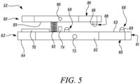
- Figure 5 is a side view
- Figure 6 is a plan view
- Figure 7 is an end view.
- the gauge assembly 52 of the compressor variable angle measurement system 50 has a baseplate 60 that has a first section 61, a second section 62, a first surface 63, a second surface 64, a first side 65 and a second side 66.
- the baseplate can be composed of any substance suitable for the purpose.
- the baseplate is composed or a metal or metal alloy, for example, a rigid plastic material, or a composite material, e.g. carbon fibre.
- each vane contact portion includes a vane contact cushion 69, which e.g. may be hemispherical in shape and which e.g. may be composed of a scratch-resistant plastic/polymer material.
- the number of vane contact portions 68 that are provided on the baseplate can vary as required. In some embodiments three vane contact portions 68 are provided on the baseplate as this usefully balances the provision of effective support for the variable vane with the desire to minimise the possibility of the variable vane being scratched or otherwise damaged.
- the baseplate 60 of the gauge assembly 52 includes an inertial measurement unit (IMU) 70.
- IMUs are electronic sensor devices that function as accelerometers, gyroscopes and/or magnetometer. The purpose of IMU will be explained below.
- the IMU can take various forms. Suitable IMUs are commercially available, one such IMU being the Variense TM VMU931 inertial measurement unit, which is a round IMU with a diameter of 31 mm, that can accommodate up to 3-axis accelerometers, 3-axis gyros, 3-axis magnetic, temperature sensors in a robust aluminium housing. It is shock resistant, splashproof and dustproof.
- the baseplate 60 of the gauge assembly 52 also includes a radial setting pin 72 that extends from the first side 65 of the gauge assembly.
- the radial setting pin is used to set the gauge assembly at a consistent height along the variable vane, the height being equivalent to the location along wingspan.
- the radial setting pin 72 is elongate and in some embodiments it has a substantially circular cross-section. The purpose of radial setting pin will be explained in more detail below.
- the baseplate 60 of the gauge assembly 52 also has two or more TE contact pins 74 which to ensure alignment of the gauge assembly at a fixed angle relative to the vane spindle axis of the variable vane.
- the two or more TE contact pins are located on the first surface 63 of the baseplate.
- the baseplate 60 has a pair of TE contact pins 74, one TE contact pin is located on the first surface 63 of the baseplate adjacent the first side 65 of the baseplate, and the other TE contact pin is located on the first surface 63 of the baseplate adjacent the second side 66 of the baseplate.
- the TE contact pins can be provided with TE contact pin cushions to minimise any scratching or other damage to the variable vane but this is typically not necessary as it is the leading edge or the trailing edge of the variable vane that contacts the TE contact pins rather than the pressure side or the suction side of the variable vane, which are more prone to being scratched.
- the gauge assembly 52 has a clamp arm 80 that is pivotally attached to the baseplate 60.
- the clamp arm 80 has a first end 81, a second end 82, a first surface 83, a second surface 84, a first side 85 and a second side 86.
- the clamp arm 80 can be composed of any substance suitable for the purpose.
- the clamp arm is composed or a metal or metal alloy, for example a rigid plastic material, or a composite material, e.g. carbon fibre.
- the baseplate 60 and the clamp arm 80 are composed of the same substance. In some embodiments the baseplate and the clamp arm are composed of different substances.
- the baseplate 60 and the clamp arm 80 form jaws for the gauge assembly 52 to support and retain a variable vane for its position to be accurately determined by the compressor variable angle measurement system 50.
- the clamp arm 80 has at least one vane contact portion 88, i.e. a portion that extends from the first surface 83 of the clamp 80 that is configured and positioned to contact a variable vane to be measured in the compressor variable angle measurement system whilst minimising any scratching or other damage to the variable vane.
- the vane contact portion 88 includes a vane contact cushion 89, which e.g. may be hemispherical in shape and which e.g. may be composed of a scratch-resistant plastic/polymer material.
- the number of vane contact portions 88 that are provided on the clamp can vary as required. In some embodiments a single vane contact portion 88 is provided on the clamp as this usefully balances the provision of effective support for the variable vane with the desire to minimise the possibility of the variable vane being scratched or otherwise damaged.
- the clamp arm 80 can be pivotally attached to the baseplate 60 in a variety of ways.
- the claim arm 80 has a pair of pivot portions 90, one extending from the first side 85 of the clamp arm and another extending from the second side 86 of the clamp arm.
- the pivot portions 90 are formed to be received within pivot supports that are formed in the baseplate 60 of the gauge assembly 52. These pivot supports are not shown in Figures 4 to 7 .
- the first end 81 of the clamp arm 80 is spring urged towards the first section 61 of the baseplate 60 by a spring 92 that is located between the first surface 63 of the baseplate and the first surface 83 of the clamp arm at a location between the point of pivotal attachment and the second section 62 of the baseplate and the second section 82 of the clamp arm.
- the spring 92 serves to removably grip a variable vane 44 of a gas turbine engine 10 between the clamp arm 80 of the gauge assembly 52 and the baseplate 60 of the gauge assembly 52, more particularly between the vane contact cushion 89 of the clamp arm 80 of the gauge assembly 52 and the vane contact cushions 69 of the baseplate 60 of the gauge assembly 52.
- a compression spring is shown but other spring configurations are possible including rotary, extension springs, torsion bars or pneumatic / hydraulic piston type devices.
- variable vane 44 whose position is to be determined by the compressor variable angle measurement system is placed within the jaws of the gauge assembly 52 formed by the first section 61 of the baseplate 60 and the first section 81 of the clamp arm 80.
- the variable vane 44 is held in place in the gauge assembly 52 between vane contact cushions 69 of the baseplate 60, the TE contact pin 74 of the baseplate, and the vane contact cushions 89 of the clamp arm 80.
- the gauge assembly includes seven points of contact to a variable vane (not shown): three vane contact cushions 69 on the first surface 63 of the baseplate 60 contact the underside of the variable vane, a single vane contact cushion 89 on the first surface 83 of the clamp arm 80 contacts the upper side of the variable vane, two TE contact pins 74 to contact the leading edge or the trailing edge of the variable vane, and a final steel leg in contact with the inner penny (not shown).
- Figure 8 shows a second embodiment of a gauge assembly 52 of the compressor variable angle measurement system 50 of the present invention. It includes most of the features of the first embodiment of the gauge assembly, one notable difference being the baseplate and the clamp include apertures 94 and 96 respectively. The provision of these apertures assists the user to see whilst using the equipment better. It also enables the gauge assembly to be lighter in weight.
- the figure also shows a pivot pin 99 about which the baseplate 60 pivots with respect to the clamp arm 80. The pivot pin 99 is held with pivot supports 99 that are formed in the baseplate 60.
- Figure 9 shows two gas turbine engine variable vanes, one of which being held within the second embodiment of a gauge assembly of the compressor variable angle measurement system of the present invention.
- This alternative embodiment is fundamentally identical to the embodiment represented schematically in Figures 4 to 7 .
- the gauge assembly is shown viewed with the clamp arm 80 in the foreground.
- the clamp arm 80 has an aperture through which the inertial measurement unit 70 is visible.
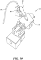
- Figure 10 shows a gas turbine engine variable vane gripped by the alternative embodiment of the gauge assembly of the compressor variable angle measurement system of the present invention shown in Figure 9 but viewed from a different angle i.e. the baseplate 60 is in the foreground.
- the compressor variable angle measurement system includes a set of gauge assemblies, each being sized and configured for the variable vanes of a particular gas turbine engine.
- the set may, for example, consist of three gauge assemblies i.e. a large, an intermediate and a small gauge assembly.
- each gauge assembly in a set of gauge assemblies may differ only in size. In certain embodiments one or more of the gauge assemblies in a set of gauge assemblies may differ in construction.
- gauge assembly 52 or more particularly the inertial measurement unit 70 of the gauge assembly, is configured to make certain measurements that are communicated to the computing device 54 for analysis and display.
- the inertial measurement unit 70 is hard-wired to the computing device 54 by a detachable cable 56, for example a conventional USB cable.
- the computing device is wirelessly connectable to the inertial measurement unit 70 via a suitable wireless technology, for example by Bluetooth ® short-range wireless technology.
- the computing device can be any device that can collect and analyse signals from the sensor module.
- the computing device is a tablet computer.
- the computing device is loaded with suitable software, for example a software application and a configuration file.
- This configuration file contains calibration parameters specific to the gauge assembly which is read by the application software upon initialisation.
- the compressor variable angle measurement system is typically constructed to be portable within a maintenance location, the computing device is ideally constructed or protected to reasonably withstand such use.
- the compressor variable angle measurement system comprises a kit that includes a set of gauge assemblies, a sensor module, and a computing device.
- the kit is supplied in a suitable case.
- the compressor variable angle measurement system of the present invention is useful for measuring Variable Stator Vane (VSV) and Variable Inlet Guide Vane (VIGV) stagger angles in gas turbine engine compressors. It can, for example generate, accurate (e.g. +/-0.2 degrees) aerodynamic stagger angles for compressor blading.
- VSV Variable Stator Vane
- VIGV Variable Inlet Guide Vane
- variable vanes in a gas turbine engine compressor can improve compressor aerodynamics and therefore compressor efficiency and engine fuel efficiency.
- variable geometry vanes in the front stages to unload the blades aerodynamically at low power to avoid compressor stall / surge.
- the vanes open gradually as the power and speed of the compressor rise and critically affect both surge margin and efficiency of the machine. Knowing the angle/positioning of variable vanes is important to understanding and controlling compressor and engine performance.
- the compressor variable angle measurement system facilitates data of sufficient fidelity to allow engine design to be modified to realise fuel burn and noise benefits.
- the application of data at the level of fidelity afforded by the system makes the system particularly useful. That is because, the current understanding of variable vane angles relies on a statistical approach to allow for tolerance stack ups between the outside of the engine where the actuation system is typically located and the vane aerodynamic surfaces. There are many line items and the resultant uncertainty can be high. However by measuring the actual aerodynamic surface orientations this can be significantly reduced. With the benefit of such data, the aerodynamic design of the compressor can be improved because of the higher confidence that design intent will be met in reality i.e. less margin required.
- transient performance as well as steady state, transient performance being important during, for e.g., engine acceleration scenarios such as go-around scenarios at approach in cases of rejected landings.
- engine acceleration scenarios such as go-around scenarios at approach in cases of rejected landings.
- Such can now be faster which is safer, or trade for noise because the aircraft can be now on a steeper approach glide path and thus generally further from the ground during approach.
- a method of positioning variable vanes in a compressor of a gas turbine engine will now be described that involves employing the compressor variable angle measurement system of the present invention.
- the method involves removably gripping a variable vane 44 of a compressor of a gas turbine engine within a gauge assembly 52 of the compressor variable angle measurement system
- step (a) of the method a variable vane of the compressor is removably gripped within a gauge assembly 52 of the compressor variable angle measurement system 50 of the present invention.
- step (a) the between the variable vane 44 is located on the first trailing edge vane engaging portion 74 and second trailing edge vane engaging portion 74 of the baseplate and gripped between the at least three vane contact portions 68 of the baseplate and the at least one vane contact portion 88 of the clamp arm.
- step (b) of the method the radial setting pin 72 is brought into contact with the penny that supports the variable vane. As explained above, the radial setting pin is used to set the gauge assembly at a consistent height along the variable vane.
- step (c) of the method the position of the variable vane is measured with respect to the radial setting pin.
- the software captures the output of the inertial measurement unit (IMU) when the user is satisfied the gauge is fitted correctly to the variable vane and initiates the recording process via the computing device (e.g. an industrial tablet computer) that contains the software, calibrations and user interface.
- the software proses the raw digital data into a vane angle that is to a consistent definition as the design mechanical drawings and aerodynamic design intent.
- the data may be stored on the tablet for each variable vane of a variable vane stage set for later retrieval and analysis.
- Measurements made by the inertial measurement unit 70 of the gauge assembly are communicated to the computing device 54 for analysis and display.
- step (c) of the method the position of the variable vane is adjusted to a desired position.
- the compressor variable angle measurement system provides information to the user. It is at the user's discretion to adjust the vane set position based on the data provided. In other words the compressor variable angle measurement system provides technical information that enables informed decision making.
Landscapes
- Engineering & Computer Science (AREA)
- Mechanical Engineering (AREA)
- General Engineering & Computer Science (AREA)
- Physics & Mathematics (AREA)
- General Physics & Mathematics (AREA)
- Geometry (AREA)
- Aviation & Aerospace Engineering (AREA)
- Radar, Positioning & Navigation (AREA)
- Remote Sensing (AREA)
- Structures Of Non-Positive Displacement Pumps (AREA)
Abstract
Description
- The present invention concerns a compressor variable angle measurement system, more particularly a system for guiding the accurate positioning of variable vanes of a compressor of a gas turbine engine.
- Gas turbine engines are typically employed to power aircraft. Typically a gas turbine engine will comprise a fan driven by an engine core. The engine core is generally made up of one or more turbines (e.g. high pressure and intermediate pressure turbines) which drive respective compressors via coaxial shafts.
- The compressors compress air that flows into the engine core and is directed into combustion equipment where it is mixed with fuel and the mixture combusted, the resulting hot combustion products expanding through and thereby driving the turbines.
- Compressors, more particularly axial compressors, typically comprise multiple stages, each stage consisting of a row of rotating blades called rotor blades that are connected to a central shaft and a row of stationary or fixed blades called stators. As air passes through each compressor stage the air pressure and temperature increases. The aerodynamic performance and handling characteristics of the compressor are largely determined by the geometries of the rotor blades and the stators in the compressor stages.
- Stators straighten or align the airflow, i.e. the swirl coming off the blades, ready for the next set of rotating blades. They are also known as stator vanes or guide vanes.
- While stator vanes are intended to be stationary in use, it can be advantageous to be able to adjust their positioning to optimise their function. Such adjustable stator vanes are known as variable stator vanes or simply variable vanes. Compressors that include variable vanes are known as variable geometry compressors.
- Variable vanes can typically pivot about axes such as to vary the angle of the vane aerofoil to optimize compressor operability and/or efficiency over the compressor speed range. These variable vanes may include variable inlet guide vanes (IGV), which are located directly upstream of the first compressor stage, or variable vanes, which form part of one or more of the subsequent downstream stages in a multistage compressor. As the engine power / rotational speed of the compressor vary the vanes are rotated to optimise compressor performance for efficiency and aerodynamic stability. More specifically, variable vanes enable optimized compressor efficiency and/or operability by providing a close-coupled direction of the gas flow into the immediately downstream compressor rotor, and/or may introduce swirl into the compressor rotor to improve low speed operability of the compressor, and thus the engine, as well as to increase the flow capacity at high speeds.
- Each variable vane typically has an aerofoil cross-section with an integral spindle to allow rotation or variation of stagger. It is mounted in bushes in a casing or inner shroud ring and has a lever fitted to its outer end. The levers are connected to a unison ring via spherical bearings so that when the unison ring is rotated the vanes all re-stagger together. The casing or inner shroud ring is known as a penny.
- When building a gas turbine engine the variable vanes must be set at the intended stagger angle(s). This however is difficult in practice due to multiple sources of mechanical tolerance being at play, especially to achieve the desirably high levels of consistency and accuracy that are needed to optimise compressor and engine performance.
- To allow for such variations in setting stagger angles it is necessary to introduce margins in to the design of the engine that cover worst case scenarios of noncompliance with aerodynamic design intent, i.e. "malschedule". These allowances include compromises to compressor aerodynamics and engine acceleration / deceleration times. Compromises to compressor efficiency adversely affect fuel efficiency. And compromises to acceleration adversely affect landing glide scope capture ability.
- It is known to use an inclinometer to set the stagger angle of a compressor variable vane. An inclinometer or clinometer is an instrument used for measuring angles of slope (or tilt), elevation, or depression of an object with respect to gravity's direction. Handheld clinometers are used for a variety of surveying and measurement tasks.
- United States patent application
US 2018/058246 A1 discloses a variable vane mechanism for adjusting the angle of stator vanes in a gas turbine engine. The mechanism includes a circumferentially extending unison ring that is driven circumferentially around a casing by an actuator. The unison ring is connected to the stator vanes via levers such that the angle of the vanes changes with circumferential movement of the unison ring. The unison ring and the casing are each provided with at least one rigging hole in order to set the initial angle of the vanes. At least one of the unison ring and the casing are each provided with at least two rigging holes, so that the initial angle of the vanes can be adjusted by selecting different combinations of rigging holes. This may allow accumulations in tolerances to be compensated for and/or may allow the engine to be tested at different initial vane angles. However it does not provide the aerodynamic stagger angles necessary to understand the aerodynamic performance of a compressor. - Some known inclinometers have rotating arms with electrical contactors or mechanical contact points that bear against the surface of an aerofoil and various angles are measured by rotary encoders and/or mechanical protractors. However experience has demonstrated that such inclinometers are operator sensitive and prone to significant operator to operator discrepancies.
- Other known inclinometers include optical sensors but they are designed to measure exterior engine features, e.g. actuator arms, rather than internal engine components such as aerofoils. And they are generally incapable of providing the richness of data or accuracy needed to usefully inform the effective design of inclinometers and/or the effective positioning of internal engine components such as aerofoils using inclinometers.
- It is therefore desirable to provide an approved compressor variable angle measurement system or at least a system that provides a useful alternative to known compressor vane installation systems and methods.
- The present invention provides a compressor variable angle measurement system, a gas turbine engine, and a method as set out in the appended claims.
- In a first aspect the present invention provides a compressor variable angle measurement system for guiding the positioning variable vanes supported on a penny of a compressor of a gas turbine engine, the compressor variable angle measurement system comprising a gauge assembly that is connectable to a computing device; the gauge assembly comprises: a baseplate that has a first section and a second section, the first section having a first trailing edge vane engaging portion, a second trailing edge vane engaging portion, at least three vane contact portions, and a radial setting pin, the second section having an inertial measurement unit, the radial setting pin being configured to contact the penny that supports the vane; a clamp arm that is pivotally attached to the baseplate and has a first section that has a vane contact portion, the first section of the clamp arm being spring urged towards the first section of the baseplate; the gauge assembly being configured to removably grip a variable vane between the vane contact portions of the baseplate and the vane contact portion of the clamp arm and on the first trailing edge vane engaging portion and the second trailing edge vane engaging portion of the base plate, the stagger angle of the variable vane with respect to the radial setting pin being determined by the computing device from measurements made by the inertial measurement unit.
- The compressor variable angle measurement system generates accurate (for example. +/-0.2 degrees) aerodynamic stagger angles for compressor blading.
- The compressor variable angle measurement system facilitates data of sufficient fidelity to allow engine design to be modified to realise fuel burn and noise benefits.
- Such a system is useful for reducing malschedule uncertainty.
- In some embodiments the first trailing edge vane engaging portion and the second trailing edge vane engaging portion are located adjacent where the baseplate is pivotally attached to the clamp arm.
- In some embodiments the first trailing edge vane engaging portion and the second trailing edge vane engaging portion are located adjacent pivot portions formed in the clamp arm about which the baseplate is pivotally attached to the clamp arm.
- In some embodiments the first trailing edge vane engaging portion and the second trailing edge vane engaging portion are located adjacent pivot supports formed in the baseplate about which the clamp arm is pivotally attached to the baseplate.
- In some embodiments the vane contact portions of the baseplate have vane contact cushions. These assist to prevent or at least minimise any scratching or other damage to the surface of the vane.
- In some embodiments the vane contact cushions are formed of nylon. Nylon has a sufficiently low coefficient of friction to enable the vane contact cushions to slide on the surface of a variable vane thereby avoiding or at least minimising any scratching or other damage to the surface of the vane.
- In some embodiments the or each vane contact portion of the clamp arm has a vane contact cushion. These assist to prevent or at least minimise any scratching or other damage to the surface of the vane.
- In some embodiments the vane contact cushions are formed of nylon. Nylon has a sufficiently low coefficient of friction to enable the vane contact cushion to slide on the surface of a variable vane thereby avoiding or at least minimising any scratching or other damage to the surface of the vane.
- In some embodiments the baseplate and/or the clamp arm include an aperture. The provision of such apertures assists the user to see whilst using the equipment better. It also enables the gauge assembly to be lighter in weight.
- In some embodiments the radial setting pin is elongate and/or has a substantially circular cross-section.
- In some embodiments the compressor variable angle measurement system comprises a set of guide assemblies configured to measure the positioning of different variable vanes in the gas turbine engine. This reflects that the size of variable vanes typically differs within a gas turbine engine and that the size of variable vanes typically differs between engine models. For a given engine model a set of guide assemblies may, for example, consist of three gauge assemblies i.e. a large, an intermediate and a small gauge assembly.
- In a second aspect the present invention provides a gas turbine engine that has variable vanes positioned by guidance obtained from the compressor variable angle measurement system of the first aspect. The judicious positioning of variable vanes in a gas turbine engine compressor can improve compressor aerodynamics and therefore compressor efficiency and engine fuel efficiency.
- In a third aspect the present invention provides a method of positioning variable vanes in a compressor of a gas turbine engine, the method comprising the steps of: (a) removably gripping a variable vane of the compressor within a gauge assembly of the compressor variable angle measurement system of the first aspect; (b) bringing the radial setting pin into contact with the penny that supports the vane; (c) measuring the position of the variable vane with respect to the radial setting pin; and (c) adjusting the position of the variable vane to a desired position informed by data obtained from the compressor variable angle measurement system.
- In some embodiments in step (a) the variable vane is located on the first trailing edge vane engaging portion and the second trailing edge vane engaging portion of the baseplate and gripped between the at least three vane contact portions of the baseplate and the at least one vane contact portion of the clamp arm.
- The term "compressor variable vane" as used herein means a stator vane of a compressor of a gas turbine engine that is moveable in angle to set compressor aerodynamics performance at different operating points.
- The term "stagger angle" as used herein means the aerodynamic stagger angle of the aerofoil.
- The term "baseplate angle" as used herein means the angle of the baseplate of the gauge (specifically the underside which is datum). This angle has a fixed relationship with stagger angle and differs from one vane design to another / engine type and stage.
- The term "cottage roof angle" as used herein means the angle of the mechanical feature on the end of the vane spindle that is used to apply torque to a variable vane to rotate it around the spindle axis. This angle has a fixed relationship with stagger angle and differs from one vane design to another / engine type and stage.
- The term "aero stagger angle" as used herein is the sum of the baseplate angle, the cottage roof angle and another offset angle.
- The term "vane average baseplate angle" as used herein means the average of the whole set of baseplate angle measurements for a given stage/row of vanes.
- The term "aero stagger delta values" as used herein means the delta stagger angle relative to design intent.
- The term "vane average aero stagger angle" as used herein means as vane average baseplate angle but aero stagger angle. It is calculated by summing the vane average baseplate angle the appropriate delta angle between baseplate and aero stagger angle from the config. file, determined at initialisation.
- Other than in the operating examples, or where otherwise indicated, all numbers expressing quantities or measures used herein are to be understood as modified in all instances by the term "about".
- Throughout this specification and in the claims that follow, unless the context requires otherwise, the word "comprise" or variations such as "comprises" and "comprising", will be understood to imply the inclusion of a stated integer or group of integers but not the exclusion of any other stated integer or group of integers.
- The skilled person will appreciate that except where mutually exclusive, a feature described in relation to any one of the above aspects may be applied mutatis mutandis to any other aspect. Furthermore except where mutually exclusive any feature described herein may be applied to any aspect and/or combined with any other feature described herein.
- Embodiments will now be described by way of example only, with reference to the Figures, in which:
-
Figure 1 is a schematic sectional side view of a gas turbine engine, more particularly a geared turbofan aircraft engine. -
Figure 2 is a schematic close up sectional side view of an upstream portion of the gas turbine engine shown inFigure 1 . -
Figure 3 is a sectional side view of a high pressure compressor of a gas turbine engine -
Figure 4 is a schematic side perspective view of a compressor variable angle measurement system of the present invention. -
Figure 5 is a schematic side view of the compressor variable angle measurement system of the present invention shown inFigure 4 . -
Figure 6 is a schematic plan view of the compressor variable angle measurement system of the present invention shown inFigures 4 and5 . -
Figure 7 is a schematic end view of the compressor variable angle measurement system of the present invention shown inFigures 4 ,5 and6 . -
Figure 8 shows an alternative embodiment of a gauge assembly of the compressor variable angle measurement system of the present invention. -
Figure 9 shows two gas turbine engine variable vanes, one of which being held within the gauge assembly shown inFigure 8 . -
Figure 10 shows a gas turbine engine variable vane gripped by the gauge assembly shown inFigure 8 and9 viewed from a different angle. - The following table lists the reference numerals used in the drawings with the features to which they refer:
Ref no. Feature A Core airflow B Bypass airflow 9 Principal and rotational axis (of engine) 10 Gas turbine engine 11 Engine core 12 Air intake 14 Low pressure compressor 15 High pressure compressor 16 Combustion equipment 17 High pressure turbine 18 Bypass exhaust nozzle 19 Low pressure turbine 20 Core exhaust nozzle 21 Fan nacelle 22 Bypass duct 23 Fan 24 Stationary supporting structure (ESS) 26 Shaft 27 Shaft 28 Sun gear 30 Epicyclic gearbox 32 Planet gear 34 Planet carrier 36 Linkage 38 Ring gear 40 Linkage 42 Rotor bade 44 Stator blade / variable vane 50 Compressor variable angle measurement system 52 Gauge assembly 54 Computing device 56 Cable 60 Baseplate 61 First section of baseplate 62 Second section of baseplate 63 First surface of baseplate 64 Second surface of baseplate 65 First side of baseplate 66 Second side of baseplate 68 Vane contact portion(s) 69 Vane contact cushion 70 Inertial measurement unit (IMU) 72 Radial setting pin 74 Trailing edge contact pin (vane engaging portion) 80 Clamp arm 81 First section of clamp arm 82 Second section of clamp arm 83 First surface of clamp arm 84 Second surface of clamp arm 85 First side of clamp arm 86 Second side of clamp arm 88 Vane contact portion(s) 89 Vane contact cushion 90 Pivot portions 92 Spring 94 Base plate aperture 96 Clamp arm aperture 98 Pivot pin 99 Pivot support - Aspects and embodiments of the present invention will now be discussed with reference to the accompanying drawings. Further aspects and embodiments will be apparent to those skilled in the art.
- The present invention concerns a compressor variable angle measurement system, more particularly a system for guiding the accurate positioning of variable vanes of a compressor of a gas turbine engine.
- High pressure ratio axial compressors require variable geometry (angle) vanes in the front stages to unload the blades aerodynamically at low power to avoid compressor stall / surge. The vanes open gradually as the power and speed of the compressor rise and critically affect both surge margin and efficiency of the machine.
- The angle of the vanes is important to understanding and controlling the behaviours of the compressor and engine. The vanes are typically controlled by circumferential unison rings rotated by hydraulic rams. The circumferential setting of the rings is currently achieved by rigging pins which pass radially through the rings to locate in the compressor case. However, there are geometrical tolerance stack ups to be accounted between ring location and where the aerodynamic surfaces are pointing and these are open to critique.
- In a first aspect the present invention provides compressor variable angle measurement system for guiding the positioning variable vanes within a compressor of a gas turbine engine.
-
Figure 1 illustrates agas turbine engine 10 having a principalrotational axis 9. Theengine 10 comprises anair intake 12 which receives air and apropulsive fan 23 generates two airflows: a core airflow A and a bypass airflow B. Air intake airflow comprises the sum total of the air flowing into the operational upstream end of theengine 10, with the sum total of the core airflow A and the bypass airflow B substantially equal to the intake airflow. - The
gas turbine engine 10 comprises a core 11 that receives the core airflow A. Theengine core 11 comprises, in axial flow series, alow pressure compressor 14, a high-pressure compressor 15,combustion equipment 16, a high-pressure turbine 17, alow pressure turbine 19 and acore exhaust nozzle 20. Anacelle 21 surrounds thegas turbine engine 10 and defines abypass duct 22 and abypass exhaust nozzle 18. The bypass airflow B flows through thebypass duct 22. Thefan 23 is attached to and driven by thelow pressure turbine 19 via ashaft 26 and anepicyclic gearbox 30. - In use, the core airflow A is accelerated and compressed by the
low pressure compressor 14 and directed into thehigh pressure compressor 15 where further compression takes place. The compressed air exhausted from thehigh pressure compressor 15 is directed into thecombustion equipment 16 where it is mixed with fuel and the mixture is combusted. The resultant hot combustion products then expand through, and thereby drive, the high pressure andlow pressure turbines nozzle 20 to provide some propulsive thrust. Thehigh pressure turbine 17 drives thehigh pressure compressor 15 by a suitable interconnectingshaft 27. Thefan 23 generally provides the majority of the propulsive thrust. Theepicyclic gearbox 30 is a reduction gearbox. - An exemplary arrangement for a geared fan
gas turbine engine 10 is shown inFigure 2 . The low pressure turbine 19 (seeFigure 1 ) drives theshaft 26, which is coupled to a sun wheel, or sun gear, 28 of theepicyclic gear arrangement 30. Radially outwardly of thesun gear 28 and intermeshing therewith is a plurality of planet gears 32 that are coupled together by aplanet carrier 34. Theplanet carrier 34 constrains the planet gears 32 to precess around thesun gear 28 in synchronicity whilst enabling eachplanet gear 32 to rotate about its own axis. Theplanet carrier 34 is coupled vialinkages 36 to thefan 23 in order to drive its rotation about theengine axis 9. Radially outwardly of the planet gears 32 and intermeshing therewith is an annulus orring gear 38 that is coupled, vialinkages 40, to a stationary supportingstructure 24. - Note that the terms "low pressure turbine" and "low pressure compressor" as used herein may be taken to mean the lowest pressure turbine stages and lowest pressure compressor stages (i.e. not including the fan 23) respectively and/or the turbine and compressor stages that are connected together by the interconnecting
shaft 26 with the lowest rotational speed in the engine (i.e. not including the gearbox output shaft that drives the fan 23). In some literature, the "low pressure turbine" and "low pressure compressor" referred to herein may alternatively be known as the "intermediate pressure turbine" and "intermediate pressure compressor". Where such alternative nomenclature is used, thefan 23 may be referred to as a first, or lowest pressure, compression stage. - The present invention concerns a system for accurately positioning variable vanes of a compressor of a gas turbine engine. Such variable vanes are typically stators.
Figure 3 is a sectional side view of thehigh pressure compressor 15 of thegas turbine engine 10 depicted inFigures 1 and2 . The drawing identifiesrotor blades 42 andstators blades 44 within thelow pressure compressor 14. The stator blades are variable stator vanes (VSV). The present invention concerns the accurate positioning of such vanes. - In a first aspect the present invention provides a compressor variable angle measurement system. Such a system is depicted in
Figure 4 . The compressor variableangle measurement system 50 comprises agauge assembly 52 and acomputing device 54. The gauge assembly is connectable to the computing device but the manner of that connection is described in more detail below. - Various views of the
gauge assembly 50 shown inFigure 4 are provided inFigures 5 ,6 and7 .Figure 5 is a side view,Figure 6 is a plan view andFigure 7 is an end view. - The
gauge assembly 52 of the compressor variableangle measurement system 50 has abaseplate 60 that has afirst section 61, asecond section 62, afirst surface 63, asecond surface 64, afirst side 65 and asecond side 66. The baseplate can be composed of any substance suitable for the purpose. In certain embodiments the baseplate is composed or a metal or metal alloy, for example, a rigid plastic material, or a composite material, e.g. carbon fibre. - The
baseplate 60 has at least threevane contact portions 68, i.e. portions that extend from thefirst surface 63 of thebaseplate 60 that are configured and positioned to contact a variable vane to be measured in the compressor variable angle measurement system whilst minimising any scratching or other damage to the variable vane. In some embodiments, as shown inFigures 4 to 7 , each vane contact portion includes avane contact cushion 69, which e.g. may be hemispherical in shape and which e.g. may be composed of a scratch-resistant plastic/polymer material. - The number of
vane contact portions 68 that are provided on the baseplate can vary as required. In some embodiments threevane contact portions 68 are provided on the baseplate as this usefully balances the provision of effective support for the variable vane with the desire to minimise the possibility of the variable vane being scratched or otherwise damaged. - The
baseplate 60 of thegauge assembly 52 includes an inertial measurement unit (IMU) 70. IMUs are electronic sensor devices that function as accelerometers, gyroscopes and/or magnetometer. The purpose of IMU will be explained below. The IMU can take various forms. Suitable IMUs are commercially available, one such IMU being the Variense™ VMU931 inertial measurement unit, which is a round IMU with a diameter of 31 mm, that can accommodate up to 3-axis accelerometers, 3-axis gyros, 3-axis magnetic, temperature sensors in a robust aluminium housing. It is shock resistant, splashproof and dustproof. - The
baseplate 60 of thegauge assembly 52 also includes aradial setting pin 72 that extends from thefirst side 65 of the gauge assembly. The radial setting pin is used to set the gauge assembly at a consistent height along the variable vane, the height being equivalent to the location along wingspan. In some embodiments theradial setting pin 72 is elongate and in some embodiments it has a substantially circular cross-section. The purpose of radial setting pin will be explained in more detail below. - The
baseplate 60 of thegauge assembly 52 also has two or more TE contact pins 74 which to ensure alignment of the gauge assembly at a fixed angle relative to the vane spindle axis of the variable vane. The two or more TE contact pins are located on thefirst surface 63 of the baseplate. In some embodiments, including the embodiment shown inFigures 4 to 7 , thebaseplate 60 has a pair of TE contact pins 74, one TE contact pin is located on thefirst surface 63 of the baseplate adjacent thefirst side 65 of the baseplate, and the other TE contact pin is located on thefirst surface 63 of the baseplate adjacent thesecond side 66 of the baseplate. The TE contact pins can be provided with TE contact pin cushions to minimise any scratching or other damage to the variable vane but this is typically not necessary as it is the leading edge or the trailing edge of the variable vane that contacts the TE contact pins rather than the pressure side or the suction side of the variable vane, which are more prone to being scratched. - The
gauge assembly 52 has aclamp arm 80 that is pivotally attached to thebaseplate 60. Theclamp arm 80 has afirst end 81, asecond end 82, afirst surface 83, asecond surface 84, afirst side 85 and asecond side 86. Theclamp arm 80 can be composed of any substance suitable for the purpose. In certain embodiments the clamp arm is composed or a metal or metal alloy, for example a rigid plastic material, or a composite material, e.g. carbon fibre. - In some embodiments the
baseplate 60 and theclamp arm 80 are composed of the same substance. In some embodiments the baseplate and the clamp arm are composed of different substances. - The
baseplate 60 and theclamp arm 80 form jaws for thegauge assembly 52 to support and retain a variable vane for its position to be accurately determined by the compressor variableangle measurement system 50. - The
clamp arm 80 has at least onevane contact portion 88, i.e. a portion that extends from thefirst surface 83 of theclamp 80 that is configured and positioned to contact a variable vane to be measured in the compressor variable angle measurement system whilst minimising any scratching or other damage to the variable vane. In some embodiments, as shown inFigures 4 to 7 , thevane contact portion 88 includes avane contact cushion 89, which e.g. may be hemispherical in shape and which e.g. may be composed of a scratch-resistant plastic/polymer material. - The number of
vane contact portions 88 that are provided on the clamp can vary as required. In some embodiments a singlevane contact portion 88 is provided on the clamp as this usefully balances the provision of effective support for the variable vane with the desire to minimise the possibility of the variable vane being scratched or otherwise damaged. - The
clamp arm 80 can be pivotally attached to thebaseplate 60 in a variety of ways. In some embodiments, including the embodiment shown inFigures 4 to 7 , theclaim arm 80 has a pair ofpivot portions 90, one extending from thefirst side 85 of the clamp arm and another extending from thesecond side 86 of the clamp arm. Thepivot portions 90 are formed to be received within pivot supports that are formed in thebaseplate 60 of thegauge assembly 52. These pivot supports are not shown inFigures 4 to 7 . - The
first end 81 of theclamp arm 80 is spring urged towards thefirst section 61 of thebaseplate 60 by aspring 92 that is located between thefirst surface 63 of the baseplate and thefirst surface 83 of the clamp arm at a location between the point of pivotal attachment and thesecond section 62 of the baseplate and thesecond section 82 of the clamp arm. Thespring 92 serves to removably grip avariable vane 44 of agas turbine engine 10 between theclamp arm 80 of thegauge assembly 52 and thebaseplate 60 of thegauge assembly 52, more particularly between thevane contact cushion 89 of theclamp arm 80 of thegauge assembly 52 and the vane contact cushions 69 of thebaseplate 60 of the gauge assembly 52.For illustrative purposes, a compression spring is shown but other spring configurations are possible including rotary, extension springs, torsion bars or pneumatic / hydraulic piston type devices. - In use a
variable vane 44 whose position is to be determined by the compressor variable angle measurement system is placed within the jaws of thegauge assembly 52 formed by thefirst section 61 of thebaseplate 60 and thefirst section 81 of theclamp arm 80. Thevariable vane 44 is held in place in thegauge assembly 52 between vane contact cushions 69 of thebaseplate 60, theTE contact pin 74 of the baseplate, and the vane contact cushions 89 of theclamp arm 80. - In certain embodiments, including the one shown in
Figures 4 to 7 , the gauge assembly includes seven points of contact to a variable vane (not shown): three vane contact cushions 69 on thefirst surface 63 of thebaseplate 60 contact the underside of the variable vane, a singlevane contact cushion 89 on thefirst surface 83 of theclamp arm 80 contacts the upper side of the variable vane, two TE contact pins 74 to contact the leading edge or the trailing edge of the variable vane, and a final steel leg in contact with the inner penny (not shown). -
Figure 8 shows a second embodiment of agauge assembly 52 of the compressor variableangle measurement system 50 of the present invention. It includes most of the features of the first embodiment of the gauge assembly, one notable difference being the baseplate and the clamp include apertures 94 and 96 respectively. The provision of these apertures assists the user to see whilst using the equipment better. It also enables the gauge assembly to be lighter in weight. The figure also shows apivot pin 99 about which thebaseplate 60 pivots with respect to theclamp arm 80. Thepivot pin 99 is held with pivot supports 99 that are formed in thebaseplate 60. -
Figure 9 shows two gas turbine engine variable vanes, one of which being held within the second embodiment of a gauge assembly of the compressor variable angle measurement system of the present invention. This alternative embodiment is fundamentally identical to the embodiment represented schematically inFigures 4 to 7 . The gauge assembly is shown viewed with theclamp arm 80 in the foreground. In this alternative embodiment theclamp arm 80 has an aperture through which theinertial measurement unit 70 is visible. -
Figure 10 shows a gas turbine engine variable vane gripped by the alternative embodiment of the gauge assembly of the compressor variable angle measurement system of the present invention shown inFigure 9 but viewed from a different angle i.e. thebaseplate 60 is in the foreground. - In certain embodiments the compressor variable angle measurement system includes a set of gauge assemblies, each being sized and configured for the variable vanes of a particular gas turbine engine. The set may, for example, consist of three gauge assemblies i.e. a large, an intermediate and a small gauge assembly.
- In certain embodiments each gauge assembly in a set of gauge assemblies may differ only in size. In certain embodiments one or more of the gauge assemblies in a set of gauge assemblies may differ in construction.
- In any case the
gauge assembly 52, or more particularly theinertial measurement unit 70 of the gauge assembly, is configured to make certain measurements that are communicated to thecomputing device 54 for analysis and display. - In some embodiments, such as that shown in
Figure 4 , theinertial measurement unit 70 is hard-wired to thecomputing device 54 by adetachable cable 56, for example a conventional USB cable. In other embodiments the computing device is wirelessly connectable to theinertial measurement unit 70 via a suitable wireless technology, for example by Bluetooth® short-range wireless technology. - The computing device can be any device that can collect and analyse signals from the sensor module. In some embodiments the computing device is a tablet computer. The computing device is loaded with suitable software, for example a software application and a configuration file. This configuration file contains calibration parameters specific to the gauge assembly which is read by the application software upon initialisation. As the compressor variable angle measurement system is typically constructed to be portable within a maintenance location, the computing device is ideally constructed or protected to reasonably withstand such use.
- In some embodiments the compressor variable angle measurement system comprises a kit that includes a set of gauge assemblies, a sensor module, and a computing device. The kit is supplied in a suitable case.
- The compressor variable angle measurement system of the present invention is useful for measuring Variable Stator Vane (VSV) and Variable Inlet Guide Vane (VIGV) stagger angles in gas turbine engine compressors. It can, for example generate, accurate (e.g. +/-0.2 degrees) aerodynamic stagger angles for compressor blading.
- The judicious positioning of variable vanes in a gas turbine engine compressor can improve compressor aerodynamics and therefore compressor efficiency and engine fuel efficiency.
- High pressure ratio axial compressors require variable geometry (angle) vanes in the front stages to unload the blades aerodynamically at low power to avoid compressor stall / surge. The vanes open gradually as the power and speed of the compressor rise and critically affect both surge margin and efficiency of the machine. Knowing the angle/positioning of variable vanes is important to understanding and controlling compressor and engine performance.
- The compressor variable angle measurement system facilitates data of sufficient fidelity to allow engine design to be modified to realise fuel burn and noise benefits. The application of data at the level of fidelity afforded by the system makes the system particularly useful. That is because, the current understanding of variable vane angles relies on a statistical approach to allow for tolerance stack ups between the outside of the engine where the actuation system is typically located and the vane aerodynamic surfaces. There are many line items and the resultant uncertainty can be high. However by measuring the actual aerodynamic surface orientations this can be significantly reduced. With the benefit of such data, the aerodynamic design of the compressor can be improved because of the higher confidence that design intent will be met in reality i.e. less margin required. This extends to transient performance as well as steady state, transient performance being important during, for e.g., engine acceleration scenarios such as go-around scenarios at approach in cases of rejected landings. Such can now be faster which is safer, or trade for noise because the aircraft can be now on a steeper approach glide path and thus generally further from the ground during approach.
- A method of positioning variable vanes in a compressor of a gas turbine engine will now be described that involves employing the compressor variable angle measurement system of the present invention.
- The method involves removably gripping a
variable vane 44 of a compressor of a gas turbine engine within agauge assembly 52 of the compressor variable angle measurement system - In the first step, step (a) of the method, a variable vane of the compressor is removably gripped within a
gauge assembly 52 of the compressor variableangle measurement system 50 of the present invention. - In step (a) the between the
variable vane 44 is located on the first trailing edgevane engaging portion 74 and second trailing edgevane engaging portion 74 of the baseplate and gripped between the at least threevane contact portions 68 of the baseplate and the at least onevane contact portion 88 of the clamp arm. - In the second step, step (b) of the method, the
radial setting pin 72 is brought into contact with the penny that supports the variable vane. As explained above, the radial setting pin is used to set the gauge assembly at a consistent height along the variable vane. - In the third step, step (c) of the method, the position of the variable vane is measured with respect to the radial setting pin.
- For example, the software captures the output of the inertial measurement unit (IMU) when the user is satisfied the gauge is fitted correctly to the variable vane and initiates the recording process via the computing device (e.g. an industrial tablet computer) that contains the software, calibrations and user interface. The software proses the raw digital data into a vane angle that is to a consistent definition as the design mechanical drawings and aerodynamic design intent. The data may be stored on the tablet for each variable vane of a variable vane stage set for later retrieval and analysis.
- Measurements made by the
inertial measurement unit 70 of the gauge assembly are communicated to thecomputing device 54 for analysis and display. - In the fourth step, step (c) of the method, the position of the variable vane is adjusted to a desired position.
- The compressor variable angle measurement system provides information to the user. It is at the user's discretion to adjust the vane set position based on the data provided. In other words the compressor variable angle measurement system provides technical information that enables informed decision making.
- It will be understood that the invention is not limited to the embodiments above-described and various modifications and improvements can be made without departing from the concepts described herein.
Claims (15)
- A compressor variable angle measurement system (50) for guiding the positioning variable vanes (44) supported on a penny of a compressor (14, 15) of a gas turbine engine (10), the compressor variable angle measurement system comprising a gauge assembly (52) that is connectable to a computing device (54);
the gauge assembly comprises:a baseplate (60) that has a first section (61) and a second section (62), the first section (61) having a first trailing edge vane engaging portion (74), a second trailing edge vane engaging portion (74), at least three vane contact portions (68), and a radial setting pin (72), the second section (62) having an inertial measurement unit (70), the radial setting pin being configured to contact the penny that supports the vane; anda clamp arm (80) that is pivotally attached to the baseplate and has a first section (81) that has at least one vane contact portion (88), the first section of the clamp arm being spring urged towards the first section of the baseplate;the gauge assembly being configured to removably grip a variable vane between the vane contact portions (68) of the baseplate and the at least one vane contact portion (88) of the clamp arm and on the first trailing edge vane engaging portion (74) and the second trailing edge vane engaging portion (74) of the base plate, the stagger angle of the variable vane with respect to the radial setting pin (72) being determined by the computing device (54) from measurements made by the inertial measurement unit (70). - The compressor variable angle measurement system of claim 1, wherein the first trailing edge vane engaging portion (74) and the second trailing edge vane engaging portion (74) are located adjacent where the baseplate (60) is pivotally attached to the clamp arm (80).
- The compressor variable angle measurement system of claim 2, wherein the first trailing edge vane engaging portion (74) and the second trailing edge vane engaging portion (74) are located adjacent pivot portions (90) formed in the clamp arm (80) about which the baseplate (60) is pivotally attached to the clamp arm (80).
- The compressor variable angle measurement system of claim 2, wherein the first trailing edge vane engaging portion (74) and the second trailing edge vane engaging portion (74) are located adjacent pivot supports (99) formed in the baseplate (60) about which the clamp arm (80) is pivotally attached to the baseplate.
- The compressor variable angle measurement system of any preceding claim, wherein the vane contact portions (68) of the baseplate (60) have vane contact cushions (69).
- The compressor variable angle measurement system of claim 5, wherein the vane contact cushions (69) are formed of nylon.
- The compressor variable angle measurement system of any preceding claim, wherein the at least one vane contact portion (88) of the clamp arm (80) has a vane contact cushion (89).
- The compressor variable angle measurement system of claim 7, wherein the vane contact cushion (89) is formed of nylon.
- The compressor variable angle measurement system of any preceding claim, wherein the baseplate (60) and/or the clamp arm (80) include an aperture (94, 96).
- The compressor variable angle measurement system of any preceding claim, wherein the radial setting pin (72) is elongate.
- The compressor variable angle measurement system of any preceding claim, wherein the radial setting pin (72) has a substantially circular cross-section.
- The compressor variable angle measurement system of any preceding claim, where the compressor variable angle measurement system comprises a set of guide assemblies (52) configured to measure the positioning of different variable vanes in the gas turbine engine (10).
- A gas turbine engine that has variable vanes positioned by guidance obtained from the compressor variable angle measurement system of any preceding claim.
- A method of positioning variable vanes (44) in a compressor of a gas turbine engine (10), the method comprising the steps of:(a) removably gripping a variable vane of the compressor within a gauge assembly (52) of the compressor variable angle measurement system (50) according to any one of claims 1 to 12;(b) bringing the radial setting pin (72) into contact with the penny that supports the vane;(c) measuring the position of the variable vane with respect to the radial setting pin; and(c) adjusting the position of the variable vane to a desired position informed by data obtained from the compressor variable angle measurement system.
- The method of claim 14, wherein in step (a) the variable vane (44) is located on the first trailing edge vane engaging portion (74) and the second trailing edge vane engaging portion (74) of the baseplate and gripped between the at least three vane contact portions (68) of the baseplate (60) and the at least one vane contact portion (88) of the clamp arm (80).
Applications Claiming Priority (1)
| Application Number | Priority Date | Filing Date | Title |
|---|---|---|---|
| GBGB2112281.7A GB202112281D0 (en) | 2021-08-27 | 2021-08-27 | Compressor variable angle measurement system |
Publications (2)
| Publication Number | Publication Date |
|---|---|
| EP4141220A1 true EP4141220A1 (en) | 2023-03-01 |
| EP4141220B1 EP4141220B1 (en) | 2024-11-13 |
Family
ID=77999637
Family Applications (1)
| Application Number | Title | Priority Date | Filing Date |
|---|---|---|---|
| EP22188673.2A Active EP4141220B1 (en) | 2021-08-27 | 2022-08-04 | Compressor variable angle measurement system |
Country Status (3)
| Country | Link |
|---|---|
| US (1) | US11933634B2 (en) |
| EP (1) | EP4141220B1 (en) |
| GB (1) | GB202112281D0 (en) |
Families Citing this family (1)
| Publication number | Priority date | Publication date | Assignee | Title |
|---|---|---|---|---|
| CN115060144B (en) * | 2022-06-30 | 2025-09-12 | 西安陕鼓动力股份有限公司 | A high-precision detection device and method for inlet guide vane angle |
Citations (5)
| Publication number | Priority date | Publication date | Assignee | Title |
|---|---|---|---|---|
| EP2336498A1 (en) * | 2009-12-15 | 2011-06-22 | Siemens Aktiengesellschaft | Apparatus for determining the angular position of a pivotable compressor guide vane |
| WO2014051663A1 (en) * | 2012-09-28 | 2014-04-03 | United Technologies Corporation | Alignment tool for use in a gas turbine engine |
| US20180058246A1 (en) | 2016-09-01 | 2018-03-01 | Rolls-Royce Plc | Variable stator vane rigging |
| WO2018093277A1 (en) * | 2016-11-15 | 2018-05-24 | General Electric Company | Inlet guide vane removal tools and methods |
| WO2019210997A1 (en) * | 2018-04-30 | 2019-11-07 | MTU Aero Engines AG | In-situ boroblending tool |
Family Cites Families (3)
| Publication number | Priority date | Publication date | Assignee | Title |
|---|---|---|---|---|
| US1954998A (en) | 1929-03-07 | 1934-04-17 | Hoffmann August | Gyroscopic inclinometer for aircraft |
| US7927067B2 (en) * | 2007-05-01 | 2011-04-19 | United Technologies Corporation | System and method for controlling stator assemblies |
| US9970315B2 (en) * | 2015-02-12 | 2018-05-15 | Hamilton Sundstrand Corporation | Movable vane control system |
-
2021
- 2021-08-27 GB GBGB2112281.7A patent/GB202112281D0/en not_active Ceased
-
2022
- 2022-08-04 EP EP22188673.2A patent/EP4141220B1/en active Active
- 2022-08-10 US US17/818,818 patent/US11933634B2/en active Active
Patent Citations (5)
| Publication number | Priority date | Publication date | Assignee | Title |
|---|---|---|---|---|
| EP2336498A1 (en) * | 2009-12-15 | 2011-06-22 | Siemens Aktiengesellschaft | Apparatus for determining the angular position of a pivotable compressor guide vane |
| WO2014051663A1 (en) * | 2012-09-28 | 2014-04-03 | United Technologies Corporation | Alignment tool for use in a gas turbine engine |
| US20180058246A1 (en) | 2016-09-01 | 2018-03-01 | Rolls-Royce Plc | Variable stator vane rigging |
| WO2018093277A1 (en) * | 2016-11-15 | 2018-05-24 | General Electric Company | Inlet guide vane removal tools and methods |
| WO2019210997A1 (en) * | 2018-04-30 | 2019-11-07 | MTU Aero Engines AG | In-situ boroblending tool |
Also Published As
| Publication number | Publication date |
|---|---|
| EP4141220B1 (en) | 2024-11-13 |
| GB202112281D0 (en) | 2021-10-13 |
| US11933634B2 (en) | 2024-03-19 |
| US20230130991A1 (en) | 2023-04-27 |
Similar Documents
| Publication | Publication Date | Title |
|---|---|---|
| EP3647552B1 (en) | Gas turbine engine power setting | |
| EP2412984B1 (en) | Variable diffuser for a cabin air compressor | |
| US11933634B2 (en) | Compressor variable angle measurement system | |
| EP2420653A2 (en) | Variable vane calibration method and kit | |
| CN110873647A (en) | Micro-engine roll pitch attitude test bench | |
| US12000302B2 (en) | Aircraft engine repair tool and method for removal and installation of a mid turbine frame in an aircraft engine | |
| CN117386669A (en) | Variable flow housing for blade tip clearance control | |
| EP4239282B1 (en) | System and method for inspecting fan blade tip clearance relative to an abradable fan case | |
| EP3489486B1 (en) | Mixed flow turbine wheel | |
| EP2895704B1 (en) | Gas turbine engine synchronizing ring with multi-axis joint | |
| CN113916670A (en) | Axial Load Test Apparatus and Method | |
| CN216051159U (en) | Axial loading test equipment | |
| US20220074910A1 (en) | System and method of measuring grain orientations | |
| CN117450095A (en) | Method for measuring rotation angle of adjustable flow blade of aero-engine compressor | |
| EP3317629B1 (en) | Test bench for charging devices | |
| US11739692B2 (en) | Electronic engine controller | |
| CN118327786A (en) | High pressure rotor control system | |
| CN115112515A (en) | An experimental method and device for measuring wear of graphite seal structure of aero-engine shaft | |
| Wang et al. | Half-scale transonic compressor rapid testing rig | |
| CN120274630B (en) | Pitch angle measuring device and pitch angle measuring method for fan blade | |
| US12215597B1 (en) | Gas turbine engine rotor blade geometry and method for selecting same | |
| CN119714781B (en) | A disc mechanism for a plane cascade test section for controlling an adjustable inlet angle of attack | |
| CN119435201A (en) | Sensor assembly for detecting propeller swirl in a turbine engine | |
| CN120028045A (en) | Double-degree-of-freedom sidewind generating device, aircraft engine test bench and test method | |
| CN119618645A (en) | Device for testing dynamic performance of magnetic bearing of turbomolecular pump by simulating gas loading |
Legal Events
| Date | Code | Title | Description |
|---|---|---|---|
| PUAI | Public reference made under article 153(3) epc to a published international application that has entered the european phase |
Free format text: ORIGINAL CODE: 0009012 |
|
| STAA | Information on the status of an ep patent application or granted ep patent |
Free format text: STATUS: THE APPLICATION HAS BEEN PUBLISHED |
|
| AK | Designated contracting states |
Kind code of ref document: A1 Designated state(s): AL AT BE BG CH CY CZ DE DK EE ES FI FR GB GR HR HU IE IS IT LI LT LU LV MC MK MT NL NO PL PT RO RS SE SI SK SM TR |
|
| STAA | Information on the status of an ep patent application or granted ep patent |
Free format text: STATUS: REQUEST FOR EXAMINATION WAS MADE |
|
| 17P | Request for examination filed |
Effective date: 20230306 |
|
| RBV | Designated contracting states (corrected) |
Designated state(s): AL AT BE BG CH CY CZ DE DK EE ES FI FR GB GR HR HU IE IS IT LI LT LU LV MC MK MT NL NO PL PT RO RS SE SI SK SM TR |
|
| REG | Reference to a national code |
Ref country code: DE Ref legal event code: R079 Free format text: PREVIOUS MAIN CLASS: F01D0017160000 Ipc: F04D0027000000 Ref country code: DE Ref legal event code: R079 Ref document number: 602022007653 Country of ref document: DE Free format text: PREVIOUS MAIN CLASS: F01D0017160000 Ipc: F04D0027000000 |
|
| GRAP | Despatch of communication of intention to grant a patent |
Free format text: ORIGINAL CODE: EPIDOSNIGR1 |
|
| STAA | Information on the status of an ep patent application or granted ep patent |
Free format text: STATUS: GRANT OF PATENT IS INTENDED |
|
| GRAS | Grant fee paid |
Free format text: ORIGINAL CODE: EPIDOSNIGR3 |
|
| RIC1 | Information provided on ipc code assigned before grant |
Ipc: G01B 5/24 20060101ALI20240904BHEP Ipc: F01D 25/28 20060101ALI20240904BHEP Ipc: F01D 21/00 20060101ALI20240904BHEP Ipc: F01D 17/16 20060101ALI20240904BHEP Ipc: F04D 29/56 20060101ALI20240904BHEP Ipc: F04D 27/00 20060101AFI20240904BHEP |
|
| GRAA | (expected) grant |
Free format text: ORIGINAL CODE: 0009210 |
|
| STAA | Information on the status of an ep patent application or granted ep patent |
Free format text: STATUS: THE PATENT HAS BEEN GRANTED |
|
| INTG | Intention to grant announced |
Effective date: 20240924 |
|
| AK | Designated contracting states |
Kind code of ref document: B1 Designated state(s): AL AT BE BG CH CY CZ DE DK EE ES FI FR GB GR HR HU IE IS IT LI LT LU LV MC MK MT NL NO PL PT RO RS SE SI SK SM TR |
|
| P01 | Opt-out of the competence of the unified patent court (upc) registered |
Free format text: CASE NUMBER: APP_54057/2024 Effective date: 20240930 |
|
| REG | Reference to a national code |
Ref country code: GB Ref legal event code: FG4D |
|
| REG | Reference to a national code |
Ref country code: CH Ref legal event code: EP |
|
| REG | Reference to a national code |
Ref country code: DE Ref legal event code: R096 Ref document number: 602022007653 Country of ref document: DE |
|
| REG | Reference to a national code |
Ref country code: IE Ref legal event code: FG4D |
|
| REG | Reference to a national code |
Ref country code: LT Ref legal event code: MG9D |
|
| REG | Reference to a national code |
Ref country code: NL Ref legal event code: MP Effective date: 20241113 |
|
| PG25 | Lapsed in a contracting state [announced via postgrant information from national office to epo] |
Ref country code: IS Free format text: LAPSE BECAUSE OF FAILURE TO SUBMIT A TRANSLATION OF THE DESCRIPTION OR TO PAY THE FEE WITHIN THE PRESCRIBED TIME-LIMIT Effective date: 20250313 Ref country code: HR Free format text: LAPSE BECAUSE OF FAILURE TO SUBMIT A TRANSLATION OF THE DESCRIPTION OR TO PAY THE FEE WITHIN THE PRESCRIBED TIME-LIMIT Effective date: 20241113 Ref country code: PT Free format text: LAPSE BECAUSE OF FAILURE TO SUBMIT A TRANSLATION OF THE DESCRIPTION OR TO PAY THE FEE WITHIN THE PRESCRIBED TIME-LIMIT Effective date: 20250313 |
|
| PG25 | Lapsed in a contracting state [announced via postgrant information from national office to epo] |
Ref country code: FI Free format text: LAPSE BECAUSE OF FAILURE TO SUBMIT A TRANSLATION OF THE DESCRIPTION OR TO PAY THE FEE WITHIN THE PRESCRIBED TIME-LIMIT Effective date: 20241113 Ref country code: NL Free format text: LAPSE BECAUSE OF FAILURE TO SUBMIT A TRANSLATION OF THE DESCRIPTION OR TO PAY THE FEE WITHIN THE PRESCRIBED TIME-LIMIT Effective date: 20241113 |
|
| REG | Reference to a national code |
Ref country code: AT Ref legal event code: MK05 Ref document number: 1741870 Country of ref document: AT Kind code of ref document: T Effective date: 20241113 |
|
| PG25 | Lapsed in a contracting state [announced via postgrant information from national office to epo] |
Ref country code: BG Free format text: LAPSE BECAUSE OF FAILURE TO SUBMIT A TRANSLATION OF THE DESCRIPTION OR TO PAY THE FEE WITHIN THE PRESCRIBED TIME-LIMIT Effective date: 20241113 |
|
| PG25 | Lapsed in a contracting state [announced via postgrant information from national office to epo] |
Ref country code: ES Free format text: LAPSE BECAUSE OF FAILURE TO SUBMIT A TRANSLATION OF THE DESCRIPTION OR TO PAY THE FEE WITHIN THE PRESCRIBED TIME-LIMIT Effective date: 20241113 |
|
| PG25 | Lapsed in a contracting state [announced via postgrant information from national office to epo] |
Ref country code: NO Free format text: LAPSE BECAUSE OF FAILURE TO SUBMIT A TRANSLATION OF THE DESCRIPTION OR TO PAY THE FEE WITHIN THE PRESCRIBED TIME-LIMIT Effective date: 20250213 |
|
| PG25 | Lapsed in a contracting state [announced via postgrant information from national office to epo] |
Ref country code: AT Free format text: LAPSE BECAUSE OF FAILURE TO SUBMIT A TRANSLATION OF THE DESCRIPTION OR TO PAY THE FEE WITHIN THE PRESCRIBED TIME-LIMIT Effective date: 20241113 Ref country code: LV Free format text: LAPSE BECAUSE OF FAILURE TO SUBMIT A TRANSLATION OF THE DESCRIPTION OR TO PAY THE FEE WITHIN THE PRESCRIBED TIME-LIMIT Effective date: 20241113 Ref country code: GR Free format text: LAPSE BECAUSE OF FAILURE TO SUBMIT A TRANSLATION OF THE DESCRIPTION OR TO PAY THE FEE WITHIN THE PRESCRIBED TIME-LIMIT Effective date: 20250214 |
|
| PG25 | Lapsed in a contracting state [announced via postgrant information from national office to epo] |
Ref country code: PL Free format text: LAPSE BECAUSE OF FAILURE TO SUBMIT A TRANSLATION OF THE DESCRIPTION OR TO PAY THE FEE WITHIN THE PRESCRIBED TIME-LIMIT Effective date: 20241113 |
|
| PG25 | Lapsed in a contracting state [announced via postgrant information from national office to epo] |
Ref country code: RS Free format text: LAPSE BECAUSE OF FAILURE TO SUBMIT A TRANSLATION OF THE DESCRIPTION OR TO PAY THE FEE WITHIN THE PRESCRIBED TIME-LIMIT Effective date: 20250213 |
|
| PG25 | Lapsed in a contracting state [announced via postgrant information from national office to epo] |
Ref country code: SM Free format text: LAPSE BECAUSE OF FAILURE TO SUBMIT A TRANSLATION OF THE DESCRIPTION OR TO PAY THE FEE WITHIN THE PRESCRIBED TIME-LIMIT Effective date: 20241113 |
|
| PG25 | Lapsed in a contracting state [announced via postgrant information from national office to epo] |
Ref country code: DK Free format text: LAPSE BECAUSE OF FAILURE TO SUBMIT A TRANSLATION OF THE DESCRIPTION OR TO PAY THE FEE WITHIN THE PRESCRIBED TIME-LIMIT Effective date: 20241113 |
|
| PG25 | Lapsed in a contracting state [announced via postgrant information from national office to epo] |
Ref country code: EE Free format text: LAPSE BECAUSE OF FAILURE TO SUBMIT A TRANSLATION OF THE DESCRIPTION OR TO PAY THE FEE WITHIN THE PRESCRIBED TIME-LIMIT Effective date: 20241113 |
|
| PG25 | Lapsed in a contracting state [announced via postgrant information from national office to epo] |
Ref country code: RO Free format text: LAPSE BECAUSE OF FAILURE TO SUBMIT A TRANSLATION OF THE DESCRIPTION OR TO PAY THE FEE WITHIN THE PRESCRIBED TIME-LIMIT Effective date: 20241113 |
|
| PG25 | Lapsed in a contracting state [announced via postgrant information from national office to epo] |
Ref country code: SK Free format text: LAPSE BECAUSE OF FAILURE TO SUBMIT A TRANSLATION OF THE DESCRIPTION OR TO PAY THE FEE WITHIN THE PRESCRIBED TIME-LIMIT Effective date: 20241113 |
|
| PG25 | Lapsed in a contracting state [announced via postgrant information from national office to epo] |
Ref country code: CZ Free format text: LAPSE BECAUSE OF FAILURE TO SUBMIT A TRANSLATION OF THE DESCRIPTION OR TO PAY THE FEE WITHIN THE PRESCRIBED TIME-LIMIT Effective date: 20241113 |
|
| PG25 | Lapsed in a contracting state [announced via postgrant information from national office to epo] |
Ref country code: IT Free format text: LAPSE BECAUSE OF FAILURE TO SUBMIT A TRANSLATION OF THE DESCRIPTION OR TO PAY THE FEE WITHIN THE PRESCRIBED TIME-LIMIT Effective date: 20241113 |
|
| REG | Reference to a national code |
Ref country code: DE Ref legal event code: R097 Ref document number: 602022007653 Country of ref document: DE |
|
| PG25 | Lapsed in a contracting state [announced via postgrant information from national office to epo] |
Ref country code: SE Free format text: LAPSE BECAUSE OF FAILURE TO SUBMIT A TRANSLATION OF THE DESCRIPTION OR TO PAY THE FEE WITHIN THE PRESCRIBED TIME-LIMIT Effective date: 20241113 |
|
| PLBE | No opposition filed within time limit |
Free format text: ORIGINAL CODE: 0009261 |
|
| STAA | Information on the status of an ep patent application or granted ep patent |
Free format text: STATUS: NO OPPOSITION FILED WITHIN TIME LIMIT |
|
| PGFP | Annual fee paid to national office [announced via postgrant information from national office to epo] |
Ref country code: DE Payment date: 20250827 Year of fee payment: 4 |
|
| PGFP | Annual fee paid to national office [announced via postgrant information from national office to epo] |
Ref country code: FR Payment date: 20250825 Year of fee payment: 4 |
|
| 26N | No opposition filed |
Effective date: 20250814 |
|
| REG | Reference to a national code |
Ref country code: CH Ref legal event code: H13 Free format text: ST27 STATUS EVENT CODE: U-0-0-H10-H13 (AS PROVIDED BY THE NATIONAL OFFICE) Effective date: 20260324 |
|
| PG25 | Lapsed in a contracting state [announced via postgrant information from national office to epo] |
Ref country code: MC Free format text: LAPSE BECAUSE OF FAILURE TO SUBMIT A TRANSLATION OF THE DESCRIPTION OR TO PAY THE FEE WITHIN THE PRESCRIBED TIME-LIMIT Effective date: 20241113 |
|
| PG25 | Lapsed in a contracting state [announced via postgrant information from national office to epo] |
Ref country code: LU Free format text: LAPSE BECAUSE OF NON-PAYMENT OF DUE FEES Effective date: 20250804 |
|
| PG25 | Lapsed in a contracting state [announced via postgrant information from national office to epo] |
Ref country code: CH Free format text: LAPSE BECAUSE OF NON-PAYMENT OF DUE FEES Effective date: 20250831 |