EP4141181A1 - Connection system - Google Patents
Connection system Download PDFInfo
- Publication number
- EP4141181A1 EP4141181A1 EP22191965.7A EP22191965A EP4141181A1 EP 4141181 A1 EP4141181 A1 EP 4141181A1 EP 22191965 A EP22191965 A EP 22191965A EP 4141181 A1 EP4141181 A1 EP 4141181A1
- Authority
- EP
- European Patent Office
- Prior art keywords
- connection system
- rebate
- anchors
- anchor
- former
- Prior art date
- Legal status (The legal status is an assumption and is not a legal conclusion. Google has not performed a legal analysis and makes no representation as to the accuracy of the status listed.)
- Pending
Links
Images








Classifications
-
- E—FIXED CONSTRUCTIONS
- E04—BUILDING
- E04C—STRUCTURAL ELEMENTS; BUILDING MATERIALS
- E04C5/00—Reinforcing elements, e.g. for concrete; Auxiliary elements therefor
- E04C5/16—Auxiliary parts for reinforcements, e.g. connectors, spacers, stirrups
- E04C5/162—Connectors or means for connecting parts for reinforcements
-
- E—FIXED CONSTRUCTIONS
- E04—BUILDING
- E04B—GENERAL BUILDING CONSTRUCTIONS; WALLS, e.g. PARTITIONS; ROOFS; FLOORS; CEILINGS; INSULATION OR OTHER PROTECTION OF BUILDINGS
- E04B1/00—Constructions in general; Structures which are not restricted either to walls, e.g. partitions, or floors or ceilings or roofs
- E04B1/38—Connections for building structures in general
- E04B1/48—Dowels, i.e. members adapted to penetrate the surfaces of two parts and to take the shear stresses
- E04B1/483—Shear dowels to be embedded in concrete
-
- E—FIXED CONSTRUCTIONS
- E04—BUILDING
- E04B—GENERAL BUILDING CONSTRUCTIONS; WALLS, e.g. PARTITIONS; ROOFS; FLOORS; CEILINGS; INSULATION OR OTHER PROTECTION OF BUILDINGS
- E04B1/00—Constructions in general; Structures which are not restricted either to walls, e.g. partitions, or floors or ceilings or roofs
- E04B1/38—Connections for building structures in general
- E04B1/41—Connecting devices specially adapted for embedding in concrete or masonry
- E04B1/4114—Elements with sockets
- E04B1/4121—Elements with sockets with internal threads or non-adjustable captive nuts
-
- E—FIXED CONSTRUCTIONS
- E04—BUILDING
- E04B—GENERAL BUILDING CONSTRUCTIONS; WALLS, e.g. PARTITIONS; ROOFS; FLOORS; CEILINGS; INSULATION OR OTHER PROTECTION OF BUILDINGS
- E04B1/00—Constructions in general; Structures which are not restricted either to walls, e.g. partitions, or floors or ceilings or roofs
- E04B1/02—Structures consisting primarily of load-supporting, block-shaped, or slab-shaped elements
- E04B1/04—Structures consisting primarily of load-supporting, block-shaped, or slab-shaped elements the elements consisting of concrete, e.g. reinforced concrete, or other stone-like material
- E04B1/043—Connections specially adapted therefor
-
- E—FIXED CONSTRUCTIONS
- E04—BUILDING
- E04B—GENERAL BUILDING CONSTRUCTIONS; WALLS, e.g. PARTITIONS; ROOFS; FLOORS; CEILINGS; INSULATION OR OTHER PROTECTION OF BUILDINGS
- E04B1/00—Constructions in general; Structures which are not restricted either to walls, e.g. partitions, or floors or ceilings or roofs
- E04B1/18—Structures comprising elongated load-supporting parts, e.g. columns, girders, skeletons
- E04B1/185—Connections not covered by E04B1/21 and E04B1/2403, e.g. connections between structural parts of different material
-
- E—FIXED CONSTRUCTIONS
- E04—BUILDING
- E04B—GENERAL BUILDING CONSTRUCTIONS; WALLS, e.g. PARTITIONS; ROOFS; FLOORS; CEILINGS; INSULATION OR OTHER PROTECTION OF BUILDINGS
- E04B1/00—Constructions in general; Structures which are not restricted either to walls, e.g. partitions, or floors or ceilings or roofs
- E04B1/38—Connections for building structures in general
-
- E—FIXED CONSTRUCTIONS
- E04—BUILDING
- E04B—GENERAL BUILDING CONSTRUCTIONS; WALLS, e.g. PARTITIONS; ROOFS; FLOORS; CEILINGS; INSULATION OR OTHER PROTECTION OF BUILDINGS
- E04B1/00—Constructions in general; Structures which are not restricted either to walls, e.g. partitions, or floors or ceilings or roofs
- E04B1/38—Connections for building structures in general
- E04B1/41—Connecting devices specially adapted for embedding in concrete or masonry
-
- E—FIXED CONSTRUCTIONS
- E04—BUILDING
- E04B—GENERAL BUILDING CONSTRUCTIONS; WALLS, e.g. PARTITIONS; ROOFS; FLOORS; CEILINGS; INSULATION OR OTHER PROTECTION OF BUILDINGS
- E04B1/00—Constructions in general; Structures which are not restricted either to walls, e.g. partitions, or floors or ceilings or roofs
- E04B1/38—Connections for building structures in general
- E04B1/41—Connecting devices specially adapted for embedding in concrete or masonry
- E04B1/4107—Longitudinal elements having an open profile, with the opening parallel to the concrete or masonry surface, i.e. anchoring rails
-
- E—FIXED CONSTRUCTIONS
- E04—BUILDING
- E04B—GENERAL BUILDING CONSTRUCTIONS; WALLS, e.g. PARTITIONS; ROOFS; FLOORS; CEILINGS; INSULATION OR OTHER PROTECTION OF BUILDINGS
- E04B1/00—Constructions in general; Structures which are not restricted either to walls, e.g. partitions, or floors or ceilings or roofs
- E04B1/38—Connections for building structures in general
- E04B1/41—Connecting devices specially adapted for embedding in concrete or masonry
- E04B1/4114—Elements with sockets
-
- E—FIXED CONSTRUCTIONS
- E04—BUILDING
- E04B—GENERAL BUILDING CONSTRUCTIONS; WALLS, e.g. PARTITIONS; ROOFS; FLOORS; CEILINGS; INSULATION OR OTHER PROTECTION OF BUILDINGS
- E04B1/00—Constructions in general; Structures which are not restricted either to walls, e.g. partitions, or floors or ceilings or roofs
- E04B1/38—Connections for building structures in general
- E04B1/41—Connecting devices specially adapted for embedding in concrete or masonry
- E04B1/4157—Longitudinally-externally threaded elements extending from the concrete or masonry, e.g. anchoring bolt with embedded head
-
- E—FIXED CONSTRUCTIONS
- E04—BUILDING
- E04C—STRUCTURAL ELEMENTS; BUILDING MATERIALS
- E04C5/00—Reinforcing elements, e.g. for concrete; Auxiliary elements therefor
- E04C5/01—Reinforcing elements of metal, e.g. with non-structural coatings
-
- E—FIXED CONSTRUCTIONS
- E04—BUILDING
- E04C—STRUCTURAL ELEMENTS; BUILDING MATERIALS
- E04C5/00—Reinforcing elements, e.g. for concrete; Auxiliary elements therefor
- E04C5/16—Auxiliary parts for reinforcements, e.g. connectors, spacers, stirrups
-
- E—FIXED CONSTRUCTIONS
- E04—BUILDING
- E04C—STRUCTURAL ELEMENTS; BUILDING MATERIALS
- E04C5/00—Reinforcing elements, e.g. for concrete; Auxiliary elements therefor
- E04C5/16—Auxiliary parts for reinforcements, e.g. connectors, spacers, stirrups
- E04C5/162—Connectors or means for connecting parts for reinforcements
- E04C5/163—Connectors or means for connecting parts for reinforcements the reinforcements running in one single direction
- E04C5/165—Coaxial connection by means of sleeves
-
- E—FIXED CONSTRUCTIONS
- E04—BUILDING
- E04C—STRUCTURAL ELEMENTS; BUILDING MATERIALS
- E04C5/00—Reinforcing elements, e.g. for concrete; Auxiliary elements therefor
- E04C5/16—Auxiliary parts for reinforcements, e.g. connectors, spacers, stirrups
- E04C5/162—Connectors or means for connecting parts for reinforcements
- E04C5/166—Connectors or means for connecting parts for reinforcements the reinforcements running in different directions
-
- E—FIXED CONSTRUCTIONS
- E04—BUILDING
- E04G—SCAFFOLDING; FORMS; SHUTTERING; BUILDING IMPLEMENTS OR AIDS, OR THEIR USE; HANDLING BUILDING MATERIALS ON THE SITE; REPAIRING, BREAKING-UP OR OTHER WORK ON EXISTING BUILDINGS
- E04G21/00—Preparing, conveying, or working-up building materials or building elements in situ; Other devices or measures for constructional work
- E04G21/12—Mounting of reinforcing inserts; Prestressing
- E04G21/125—Reinforcement continuity box
-
- E—FIXED CONSTRUCTIONS
- E04—BUILDING
- E04B—GENERAL BUILDING CONSTRUCTIONS; WALLS, e.g. PARTITIONS; ROOFS; FLOORS; CEILINGS; INSULATION OR OTHER PROTECTION OF BUILDINGS
- E04B1/00—Constructions in general; Structures which are not restricted either to walls, e.g. partitions, or floors or ceilings or roofs
- E04B1/02—Structures consisting primarily of load-supporting, block-shaped, or slab-shaped elements
- E04B1/04—Structures consisting primarily of load-supporting, block-shaped, or slab-shaped elements the elements consisting of concrete, e.g. reinforced concrete, or other stone-like material
-
- E—FIXED CONSTRUCTIONS
- E04—BUILDING
- E04B—GENERAL BUILDING CONSTRUCTIONS; WALLS, e.g. PARTITIONS; ROOFS; FLOORS; CEILINGS; INSULATION OR OTHER PROTECTION OF BUILDINGS
- E04B1/00—Constructions in general; Structures which are not restricted either to walls, e.g. partitions, or floors or ceilings or roofs
- E04B1/38—Connections for building structures in general
- E04B1/41—Connecting devices specially adapted for embedding in concrete or masonry
- E04B2001/4192—Connecting devices specially adapted for embedding in concrete or masonry attached to concrete reinforcing elements, e.g. rods or wires
Landscapes
- Engineering & Computer Science (AREA)
- Architecture (AREA)
- Civil Engineering (AREA)
- Structural Engineering (AREA)
- Physics & Mathematics (AREA)
- Electromagnetism (AREA)
- Mechanical Engineering (AREA)
- Reinforcement Elements For Buildings (AREA)
Abstract
Description
- The invention relates to construction and to a connection system, for example for connecting reinforcement of a floor to a wall prior to pouring concrete of the floor. The invention may also relate to a rebate former for construction. More particularly, but not exclusively, the invention relates to a rebate former for forming a rebate in a concrete component for floor and/or wall connections.
- It has been previously proposed to provide a connection system including a rebate box for providing a structural connection between concrete components. However, the applicant has identified that existing connection systems may be difficult to use, require a dense population of reinforcement anchorages and yet provide relatively low tensile capacity.
- The applicant has identified that it would be advantageous to provide an improved connection system for providing a structural connection between concrete components, which addresses one or more of the disadvantages of existing connection systems.
- Examples of the invention seek to provide an improved connection system which obviates or at least alleviates one or more disadvantages of existing connection systems, or at least to provide a useful alternative.
- In accordance with one aspect of the present invention there is provided a connection system for providing a construction joint between a first concrete component and a second concrete component, the connection system including a rebate former for forming a rebate in a first concrete component, wherein the rebate former is formed of sheet metal, the rebate former including an elongated backing, the elongated backing having folded edges to a predefined depth.
- Preferably, the connection system includes a plurality of anchors coupled to the elongated backing, each of the anchors having an internal thread for receiving an external thread of a reinforcing bar for reinforcing a second concrete component.
- Preferably, each of the anchors has a foot for providing anchorage in the first concrete component. More preferably, the foot is a tapered foot. Even more preferably, the foot is in the form of a circular tapered foot.
- In a preferred form, each of the anchors has one or more external ribs along a length of the anchor for providing anchorage in the first concrete component. More preferably, each of the external ribs is tapered outwardly toward a free end of the anchor. Even more preferably, each of the anchors is in the form of a threaded insert.
- In a preferred form, the rebate former has folded ends to provide structural rigidity.
- Preferably, the connection system includes a lid for covering an internal cavity of the rebate former defined by the elongated backing and the folded edges. More preferably, the connection system includes at least one strap extending around the rebate former and the lid to secure the lid to the rebate former.
- In one form, the rebate former includes a row of anchors mounted longitudinally of the rebate former. More preferably, the rebate former includes a plurality of parallel rows of anchors mounted longitudinally of the rebate former.
- Preferably, the connection system includes a plurality of parallel rebate formers joined by an intermediate section. More preferably, each rebate former has a plurality of rows of anchors mounted thereto.
- In a preferred form, the rebate former includes a cross strut extending across a width of the internal cavity of the rebate former. More preferably, the cross strut is in the form of a brace which is movable along a length of the rebate former.
- Preferably, each anchor is provided with a securing plug, the securing plug having an external thread for threading into the internal thread of the anchor. More preferably, the securing plug has an external thread having the same pitch as the external thread of a reinforcing bar for threading into the female thread of the anchor. Even more preferably, the securing plug is arranged with an enlarged base to facilitate threading manually by hand. In one form, the securing plug is formed of plastic material.
- Preferably, the connection system includes a resilient washer located between the securing plug and the respective anchor to facilitate a seal of the internal thread of the anchor against ingress of concrete.
- In one form, the rebate former is dimpled on the backing and on the folded edges to facilitate retention of the rebate former within surrounding concrete.
- Preferably, the connection system includes a threaded reinforcing bar threaded into each anchor, with an external thread of the threaded reinforcing bar mating with an internal thread of the anchor.
- In accordance with another aspect of the present invention, there is provided a method of providing a construction joint between a first concrete component and a second concrete component, the method including the steps of:
- providing a connection system including a rebate former for forming a rebate in the first concrete component, wherein the rebate former is formed of sheet metal, the rebate former including an elongated backing, the elongated backing having folded edges to a predefined depth;
- providing a plurality of anchors coupled to the elongated backing, each of the anchors having an internal thread;
- providing a plurality of reinforcing bars, each of the reinforcing bars having an external thread along its length; and
- threading one of the reinforcing bars into each of the anchors such that, for each anchor, an external thread of a reinforcing bar is threaded into the internal thread of the anchor to tighten the reinforcing bar relative to the anchor for providing reinforcement for the second concrete component.
- The invention is further described by way of non-limiting example only, with reference to the accompanying drawings in which:
-
Figure 1 is a perspective view of a connection system in accordance with an example of the present invention, shown prior to embedment in concrete components; -
Figure 2 is a cross-sectional view of a connection system in accordance with an example of the present invention, forming a structural connection between two concrete components; -
Figure 3 is a cross-sectional view of a connection system having a rebate former with parallel rows of anchors; -
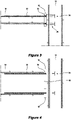
Figure 4 is a cross-sectional view of a connection system having a pair of parallel rebate formers; -
Figure 5 is a cross-sectional view of a connection system having a pair of parallel rebate formers, each with parallel rows of anchors; -
Figure 6 is a perspective view of a connection system, showing an internal cavity beneath a lid; -
Figure 7 is an end view of a connection system, depicted prior to connecting reinforcing bars to the anchors; -
Figure 8 is a perspective view of a connection system having parallel rows of anchors; -
Figure 9 is a perspective view of the connection system ofFigure 8 , shown fitted with threaded plugs; and -
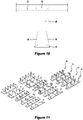
Figure 10 shows a detailed side view of an anchor of the connection system shown inFigure 9 ; -
Figure 11 shows a range of different configurations of connection systems; -
Figure 12 shows a pair of rebate formers, each with a single row of anchors; -
Figure 13 shows a plurality of rebate formers, each with a pair of anchor rows; -
Figure 14 shows a connection system having reinforcing bars connected to anchors thereof; -
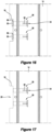
Figure 15 shows an end view of a rebate former embedded in a first concrete component; -
Figure 16 shows the rebate former ofFigure 15 shown with threaded plugs fitted; -
Figure 17 shows the rebate former ofFigure 16 with the plugs removed; -
Figure 18 shows the rebate former ofFigure 17 with reinforcing bars inserted; -
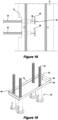
Figure 19 shows a rebate former cavity shown with a cross strut/brace; -
Figure 20 shows a table with anchorage capacity results of different anchors; -
Figure 21 shows a table of Design Capacity; -
Figure 22 shows a rebate former used with a single row of anchors; -
Figure 23 shows a rebate former used with a double row of anchors; -
Figure 24 shows a pair of rebate formers used, each with a single row of anchors; -
Figure 25 shows a pair of rebate formers used, each with a double row of anchors; -
Figure 26 shows a side view of a rebate former, depicting anchorage; -
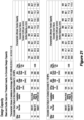
Figure 27 shows a pair of rebate formers used, each with a single row of double ended anchors; -
Figure 28 shows a range of example connections; -
Figure 29 shows both sides of a threaded plug; -
Figure 30 shows a side view of a connection system with a plug fitted to each anchor; -
Figure 30a shows a cross sectional view of a plug fitted to each anchor; -
Figure 31 shows a perspective view of a resilient washer/seal; -
Figure 32 shows a perspective view of resilient washers is being used to seal beneath threaded plugs; -
Figure 33 shows a side view of an anchor fitted to a dimpled rebate former; and -
Figure 34 shows a connection system embedded in a first concrete component prior to removal of threaded plugs. - With reference to
Figures 1 to 34 , there is shown various examples of aconnection system 10. Advantageously, theconnection system 10 has been developed by the applicant to facilitate improved rigidity, ease-of-use, efficiency and improved load-bearing capacity. - More specifically, as shown in the drawings, an example of the present invention provides a
connection system 10 for providing a construction joint 12 between a firstconcrete component 14 and a secondconcrete component 16. Theconnection system 10 includes a rebate former 18 for forming a rebate 20 (seeFigure 17 ) in the firstconcrete component 14. The rebate former 18 is formed of sheet metal, the rebate former 18 including anelongated backing 22, theelongated backing 22 having foldededges 24 to a predefined depth. - As shown clearly in
Figures 8 and 9 , theconnection system 10 includes a plurality ofanchors 26 coupled to theelongated backing 22. Each of theanchors 26 as an internal thread 28 (seeFigure 30a ) for receiving anexternal thread 30 of a reinforcingbar 32 for reinforcing the secondconcrete component 16. - Each of the
anchors 26 has afoot 34 for providing anchorage in the firstconcrete component 14. The foot may be in the form of atapered foot 34. Even more specifically, the foot may be in the form of a circulartapered foot 34. - As can be seen in
Figure 7 , each of theanchors 26 has one or moreexternal ribs 36 along a length of theanchor 26 for providing anchorage in the firstconcrete component 14. Each of theexternal ribs 36 may be tapered outwardly toward a free end of theanchor 26. Each of theanchors 26 may be in the form of a threaded insert. - The rebate former 18 may have one or more folded ends 38 to provide structural rigidity.
- The
connection system 10 may include alid 40 for covering aninternal cavity 42 of the rebate former 18 defined by theelongated backing 22 and the folded edges 24. Theconnection system 10 may include at least onestrap 44 extending around the rebate former 18 and thelid 40 to secure thelid 40 to the rebate former 18. Alternatively, with reference toFigure 6 andFigure 9 , straps 44 may instead be used around the rebate former 18 without thelid 40 fitted. - The rebate former 18 may include a row of
anchors 26 mounted longitudinally of the rebate former 18 (see, for example,Figure 12 ). In another form, the rebate former 18 may include a plurality of parallel rows ofanchors 26 mounted longitudinally of the rebate former 18 (see, for example,Figure 13 ). - The
connection system 10 may include a plurality ofparallel rebate formers 18 joined by anintermediate section 46, as shown inFigure 4 . Each rebate former 18 may have a plurality of rows ofanchors 26 mounted thereto, as shown inFigure 5 . - With reference to
Figure 6 , the rebate former 18 may include across strut 48 extending across a width of theinternal cavity 42 of the rebate former 18. Thecross strut 48 may be in the form of a brace which is movable along a length of the rebate former 18. - Also as shown in
Figure 6 , eachanchor 26 may be provided with a securingplug 50, the securingplug 50 having anexternal thread 52 for threading into theinternal thread 28 of theanchor 26. As shown inFigure 29 , the securingplug 50 may have anexternal thread 52 having the same pitch as theexternal thread 30 of a reinforcingbar 32 for threading into theinternal thread 28 of theanchor 26. This may be advantageous as theexternal thread 52 is therefore a coarse thread and is much quicker to thread in and thread out the securingplug 50 when compared with a metric thread. The securingplug 50 may be arranged with an enlarged base 54 (seeFigure 29 ) to facilitate threading manually by hand. In one form, the securingplug 50 is formed of plastic material. - The
connection system 10 may include a resilient washer 56 (seeFigure 31 and Figure 32 ) located between the securingplug 50 and therespective anchor 26 to facilitate a seal of theinternal thread 28 of theanchor 26 against ingress of concrete. - With reference to
Figure 32 , the rebate former 18 may be dimpled on thebacking 22 and on the foldededges 24 to facilitate retention of the rebate former 18 within surrounding concrete. - After casting of the first
concrete component 14 and removal of the securing plugs 50, theconnection system 10 includes a threaded reinforcingbar 32 threaded into eachanchor 26, with anexternal thread 30 of the threaded reinforcingbar 32 mating with aninternal thread 28 of the anchor 26 (seeFigure 18 ). - Advantageously, as the
anchors 26 provided with a coarse thread for threaded insertion of externally threaded reinforcingbar 32, this facilitates direct insertion of the reinforcingbar 32 into theinternal thread 28 of eachanchor 26 rather than requiring a metric thread to be tapped on to an end of the reinforcingbar 32. This may be advantageous as it may facilitate cutting on-site of a reinforcingbar 32 to size, then threading of the cup and of the reinforcingbar 32 directly into theanchor 26 without needing to form a metric thread on an end portion of the reinforcingbar 32. - Accordingly, invention also provides a method of providing a construction joint 12 between a first
concrete component 14 and a secondconcrete component 16. The method includes the steps of: - providing a
connection system 10 including a rebate former 18 for forming arebate 20 in the firstconcrete component 14, wherein the rebate former 18 is formed of sheet metal, the rebate former 18 including anelongated backing 22, theelongated backing 22 having foldededges 24 to a predefined depth; - providing a plurality of
anchors 26 coupled to theelongated backing 22, each of theanchors 26 having aninternal thread 28; - providing a plurality of reinforcing
bars 32, each of the reinforcingbars 32 having anexternal thread 30 along its length; and - threading one of the reinforcing
bars 32 into each of theanchors 26 such that, for eachanchor 26, anexternal thread 30 of a reinforcingbar 32 is threaded into theinternal thread 28 of theanchor 26 to tighten the reinforcingbar 32 relative to theanchor 26 for providing reinforcement for the secondconcrete component 16. - The following features and/or advantages may be present in examples of the invention, according to the following aspects:
-
- Pre-assembled unit ready pick and place onsite installation directly to formwork.
- Removes the requirement to drill through shuttering onsite.
- Flexibility of placement onsite vertical and horizontally.
- Standard single row configuration units to suit smaller slab sizes (140mm to 180mm) with centrally placed lap bars.
- Standard double row configuration units to suit medium to large sized slabs (190mm to 500mm) with top and bottom lap bars.
- Multiple row placement ability with single row configuration units to suit extra-large slab sizes (500mm plus). Rows placed at top and bottom of slab. Added ability to place different anchor sizes for top and bottom reinforcing.
- Multiple row placement ability with double row configuration units to suit extra-large slab sizes (500mm plus). Rows placed at top and bottom of slab. Added ability to place different anchor sizes for top and bottom reinforcing.
- Standard 1000mm unit length to facilitate simple take-off and ordering. The units can be cut onsite into infills to match specific length requirements. Internal supports can be moved to block cut ends.
- Standardised predefined rebate depth of 30mm to suit unit placement before first lay of reinforcing in the wall.
-
- Units use a perforated sheet metal base, punched as a template which accurately spaces and configures structural anchors or couplers at required centers laterally across the joint and spaces them at cover requirements for top and bottom reinforcing (on double row configurations).
- Available in different anchor sizes (RB12, RBA16, RB20, RBA20, RB25 and RB32).
- Optimised anchor/coupler centers to meet connection design parameters.
- Unit base assembly restrains attached coupler/anchors perpendicular the rebated joint face.
- The refined 30mm rebate positions the anchors at the optimal embedment depth in the wall to provide maximum shear cone efficiency.
- Rebated channel provides added positive shear resistance.
-
- Screw in structural 500 MPa lap bars for easy connection onsite.
- Optional full-length lap bar connection to floor to wall continuality system through use of a full length threaded structural reinforcing bars or a screw on coupler connection system. This reduces lapping at lap bars giving reduced bars cost of overlapping bars and congestion in reinforcing.
- Lap lengths are not limited by what can fit into the box lengths (i.e. bar laying in typical pull-out bar systems). This allows the standard 1000mm box length to be cut to any shorter infill length with easy and allows for fully developed lap lengths on these shorter lengths.
- Reduction in weight of continuity systems during setup and transport.
- Reduces exposure of tripping hazards created by pull-out bars systems.
- Improves installer exposure to repetitive stress injuries caused by bending out multiple pull-out bars.
-
- Headed anchorage rather than looped or cogged reo lap bars being tied into vertical reinforcing. The 30mm predefined rebates places the anchors at the correct embedment to maximise shear cone size and efficiency in the placed-in slab.
- Cogged anchor of design development length for correct embedment when used with coupler fittings.
- The structural anchors used are genuine Reidbar fittings optimised for use with structural Reidbar. They are manufactured to the highest quality and tolerance to match the connecting bar. When tested in concrete against theoretically calculated alternative systems they achieve up to a 30% increase in efficiency over the other systems allowing for a reduction in anchor quantities required for connections. This reduces cost of fittings and labour as well as reducing reinforcing congestion.
- Anchors optimised in centers and layers in prefabricated units to give maximum anchorage performance with minimal in place anchors.
- Standard anchor application suitable for all types rebated structural connections on multi-level projects:
- floor to wall
- wall to wall
- precast panel to floor
- precast panel to wall
- wall to capping slab
- crane penetrations
- stair flights and landings
- corbels
- beam to wall/column
-
- Secures couplers or anchors to the unit assembly with a bolt and nut functionality during setup with formwork and pouring of concrete.
- Easy attachment during manufacturing and removal onsite of nailing plates from couplers/anchors using a ½" driver and cordless drill.
- Nailing plate thread matches the thread of coupler/anchor and blocks void and thread profile during the concrete pour to prevent concrete slurry ingress into the fitting.
- Sizes available in to suit RBA16, RB20, RBA20, RB25 and RB32 Reidbar couplers and anchors.
- Rubber washer fits between coupler/anchor and nailing plate to create a secure seal to prevent slurry ingress into the rebate box unit during the concrete pour.
- Washer acts as an anti-vibration device for the nailing plates to ensure coupler/anchor remains tight until pouring.
-
- Dimpled finish on unit base helps anchors base component into the slab when stripping lid.
- The dimpled finish maximises the contact surface area between connecting slabs by up to 5%.
- Eliminates need for scabbling rebate.
- Made of galvanised sheet metal to prevent corrosion in the rebate.
- While various embodiments of the present invention have been described above, it should be understood that they have been presented by way of example only, and not by way of limitation. It will be apparent to a person skilled in the relevant art that various changes in form and detail can be made therein without departing from the spirit and scope of the invention. Thus, the present invention should not be limited by any of the above described exemplary embodiments.
- Throughout this specification and the claims which follow, unless the context requires otherwise, the word "comprise", and variations such as "comprises" and "comprising", will be understood to imply the inclusion of a stated integer or step or group of integers or steps but not the exclusion of any other integer or step or group of integers or steps.
- The reference in this specification to any prior publication (or information derived from it), or to any matter which is known, is not, and should not be taken as an acknowledgment or admission or any form of suggestion that that prior publication (or information derived from it) or known matter forms part of the common general knowledge.
List of numbered features Connection system 10 Construction joint 12 First concrete component 14 Second concrete component 16 Rebate former 18 Rebate 20 Elongated backing 22 Folded edges 24 Anchors 26 Internal thread 28 External thread 30 Reinforcing bar 32 Foot 34 External ribs 36 Folded end 38 Lid 40 Internal cavity 42 Strap 44 Intermediate section 46 Cross strut 48 Securing plug 50 External thread 52 Enlarged base 54 Resilient washer 56
Claims (15)
- A connection system for providing a construction joint between a first concrete component and a second concrete component, the connection system including a rebate former for forming a rebate in a first concrete component, wherein the rebate former is formed of sheet metal, the rebate former including an elongated backing, the elongated backing having folded edges to a predefined depth.
- A connection system as claimed in claim 1, wherein the connection system includes a plurality of anchors coupled to the elongated backing, each of the anchors having an internal thread for receiving an external thread of a reinforcing bar for reinforcing a second concrete component.
- A connection system as claimed in claim 2, wherein each of the anchors has a foot for providing anchorage in the first concrete component.
- A connection system as claimed in claim 3, wherein the foot is a tapered foot.
- A connection system as claimed in claim 2, wherein each of the anchors has one or more external ribs along a length of the anchor for providing anchorage in the first concrete component.
- A connection system as claimed in claim 2, wherein each of the anchors is in the form of a threaded insert.
- A connection system as claimed in claim 1, wherein the rebate former has folded ends to provide structural rigidity.
- A connection system as claimed in claim 1, wherein the connection system includes a lid for covering an internal cavity of the rebate former defined by the elongated backing and the folded edges.
- A connection system as claimed in claim 2, wherein the rebate former includes a row of anchors mounted longitudinally of the rebate former.
- A connection system as claimed in claim 1, including a plurality of parallel rebate formers joined by an intermediate section.
- A connection system as claimed in claim 1, wherein the rebate former includes a cross strut extending across a width of the internal cavity of the rebate former.
- A connection system as claimed in claim 2, wherein each anchor is provided with a securing plug, the securing plug having an external thread for threading into the internal thread of the anchor.
- A connection system as claimed in claim 1, wherein the rebate former is dimpled on the backing and on the folded edges to facilitate retention of the rebate former within surrounding concrete.
- A connection system as claimed in claim 2, including a threaded reinforcing bar threaded into each anchor, with an external thread of the threaded reinforcing bar mating with an internal thread of the anchor.
- A method of providing a construction joint between a first concrete component and a second concrete component, the method including the steps of:providing a connection system including a rebate former for forming a rebate in the first concrete component, wherein the rebate former is formed of sheet metal, the rebate former including an elongated backing, the elongated backing having folded edges to a predefined depth;providing a plurality of anchors coupled to the elongated backing, each of the anchors having an internal thread;providing a plurality of reinforcing bars, each of the reinforcing bars having an external thread along its length; andthreading one of the reinforcing bars into each of the anchors such that, for each anchor, an external thread of a reinforcing bar is threaded into the internal thread of the anchor to tighten the reinforcing bar relative to the anchor for providing reinforcement for the second concrete component.
Applications Claiming Priority (1)
| Application Number | Priority Date | Filing Date | Title |
|---|---|---|---|
| AU2021221844A AU2021221844A1 (en) | 2021-08-25 | 2021-08-25 | Connection system |
Publications (1)
| Publication Number | Publication Date |
|---|---|
| EP4141181A1 true EP4141181A1 (en) | 2023-03-01 |
Family
ID=83444862
Family Applications (1)
| Application Number | Title | Priority Date | Filing Date |
|---|---|---|---|
| EP22191965.7A Pending EP4141181A1 (en) | 2021-08-25 | 2022-08-24 | Connection system |
Country Status (3)
| Country | Link |
|---|---|
| US (1) | US12291861B2 (en) |
| EP (1) | EP4141181A1 (en) |
| AU (1) | AU2021221844A1 (en) |
Cited By (1)
| Publication number | Priority date | Publication date | Assignee | Title |
|---|---|---|---|---|
| EP4606963A1 (en) * | 2024-02-26 | 2025-08-27 | Illinois Tool Works Inc. | Connection system and stiffening template |
Families Citing this family (2)
| Publication number | Priority date | Publication date | Assignee | Title |
|---|---|---|---|---|
| AU2021221844A1 (en) * | 2021-08-25 | 2023-03-16 | Illinois Tool Works Inc. | Connection system |
| US20250347101A1 (en) * | 2024-05-13 | 2025-11-13 | Onx, Inc. | Method and arrangement for coupling vertical precast structures |
Citations (2)
| Publication number | Priority date | Publication date | Assignee | Title |
|---|---|---|---|---|
| EP0121510A2 (en) * | 1983-03-28 | 1984-10-10 | Claude Meyers | Anchoring box for concrete reinforcing rods |
| WO2014026024A1 (en) * | 2012-08-08 | 2014-02-13 | Illinois Tools Works Inc. | Rebate formwork system for slip form casting |
Family Cites Families (61)
| Publication number | Priority date | Publication date | Assignee | Title |
|---|---|---|---|---|
| US923188A (en) * | 1909-01-21 | 1909-06-01 | Frank N Kneas | Hanger-socket for reinforced concrete. |
| US1110429A (en) * | 1910-01-03 | 1914-09-15 | William T English | Insert for concrete construction. |
| US1110440A (en) * | 1910-01-03 | 1914-09-15 | William T English | Insert for concrete constructions. |
| US1004226A (en) * | 1911-04-18 | 1911-09-26 | Alfred M Pitts | Insert for concrete construction. |
| US1114013A (en) * | 1914-01-16 | 1914-10-20 | William B Millar | Concrete-insert. |
| US1212990A (en) * | 1915-05-21 | 1917-01-16 | Henry B Newhall Jr | Concrete-insert. |
| US1223595A (en) * | 1916-05-22 | 1917-04-24 | Frank G Mcmillan | Metallic insert. |
| US1240993A (en) * | 1916-05-22 | 1917-09-25 | Frank G Mcmillan | Metallic insert. |
| US1281416A (en) * | 1917-02-10 | 1918-10-15 | Walter M Pratt | Insert for concrete construction. |
| US1461742A (en) * | 1921-01-27 | 1923-07-17 | Edward Ogden J | Concrete insert |
| US1491571A (en) * | 1921-01-27 | 1924-04-22 | Edward Ogden J | Concrete insert |
| US1489373A (en) * | 1921-05-28 | 1924-04-08 | Edward Ogden J | Concrete insert |
| US1521658A (en) * | 1921-07-06 | 1925-01-06 | Edward Ogden J | Concrete insert |
| US1768246A (en) * | 1928-01-23 | 1930-06-24 | Globe Machine & Stamping Co | Insert for concrete |
| US1769498A (en) * | 1928-07-16 | 1930-07-01 | Omer L Downing | Concrete hanger insert |
| US1922479A (en) * | 1929-07-10 | 1933-08-15 | Pliny N Joslin | Adjustable concrete insert |
| US1929835A (en) * | 1929-11-11 | 1933-10-10 | Floor Accessories Company Inc | Concrete insert |
| US1948093A (en) * | 1931-09-05 | 1934-02-20 | Federal American Cement Tile C | Insert for cementitious slabs |
| US2181005A (en) * | 1935-05-20 | 1939-11-21 | Cal C Chambers | Dowel bar structure |
| US2133134A (en) * | 1937-07-30 | 1938-10-11 | Anthony E Davis | Concrete insert |
| US2194383A (en) * | 1939-05-11 | 1940-03-19 | Elmer S Clark | Highway joint |
| US2280080A (en) * | 1939-11-13 | 1942-04-21 | Nicholas A Predan | Concrete insert |
| US2954647A (en) * | 1957-04-11 | 1960-10-04 | Lee Hsiang Kai | Adjustable anchoring device |
| US3095672A (en) * | 1960-11-01 | 1963-07-02 | Tullio Alfred Di | Anchorage bolt and block for concrete structures |
| US3405497A (en) * | 1966-08-08 | 1968-10-15 | Lloyd L. Mcnair | Suspension device for ceilings and fixtures |
| US3449883A (en) * | 1967-07-31 | 1969-06-17 | Paltier Corp | Mounting means |
| US3559541A (en) * | 1969-07-08 | 1971-02-02 | David Watstein | Concrete joint load transfer device |
| US3694012A (en) * | 1969-11-04 | 1972-09-26 | Erico Prod Inc | Reinforcing bar coupling |
| US3722165A (en) * | 1970-08-24 | 1973-03-27 | Fredrikson G Ab | Device for mounting wall parts |
| US3744659A (en) * | 1972-04-05 | 1973-07-10 | W Koehler | Elongated rigidified container |
| US3982363A (en) * | 1974-10-18 | 1976-09-28 | Ddk Investments, Ltd. | Frangible insert |
| US4469465A (en) * | 1981-09-10 | 1984-09-04 | Andrus James S | Rebar coupler |
| DE3737645A1 (en) * | 1987-11-06 | 1989-05-24 | Schaefer Horst | Reinforcement element and method of connecting the reinforcement of reinforced-concrete structural parts which are to be concreted one after the other |
| US4905444A (en) * | 1989-06-12 | 1990-03-06 | Connection Specialties Inc. | Method and system for mounting building wall panels to building frames, incorporating mounting means elements with two degrees of motion freedom |
| US6219991B1 (en) * | 1990-08-06 | 2001-04-24 | Hexcel Corporation | Method of externally strengthening concrete columns with flexible strap of reinforcing material |
| US5230191A (en) * | 1991-05-28 | 1993-07-27 | Paul Mayrand | Precast insulated concrete panel for prefabricated building structure |
| US5261635A (en) * | 1991-12-09 | 1993-11-16 | Symons Corporation | Slab joint system and apparatus for joining concrete slabs in side-by-side relation |
| US5487249A (en) * | 1994-03-28 | 1996-01-30 | Shaw; Ronald D. | Dowel placement apparatus for monolithic concrete pour and method of use |
| US5548939A (en) * | 1994-05-25 | 1996-08-27 | Carmical; Clifton | Adjustable insert for use with concrete or steel |
| CA2209664C (en) * | 1995-01-06 | 2005-06-07 | The Burke Group | Concrete structure having load transferring insert and method for making same |
| US5625993A (en) * | 1995-01-06 | 1997-05-06 | The Burke Group | Concrete structure having load transferring insert and method for making same |
| US5635097A (en) * | 1995-02-14 | 1997-06-03 | Concrete Structures Of The Midwest, Inc. | Rebar retention apparatus |
| US5813185A (en) * | 1996-04-29 | 1998-09-29 | Jackson; George W. | Spacer reciever for a wall form tie rod |
| WO1998028500A1 (en) | 1996-12-23 | 1998-07-02 | Peter Pedrini | A joint plate for concrete |
| US5809703A (en) * | 1997-01-15 | 1998-09-22 | Mmi Products, Inc. | Slotted insert with increased pull-out capacity |
| US6065263A (en) * | 1997-06-27 | 2000-05-23 | Kaieitechno Co., Ltd. | Connecting structure for concrete block and connector used therefor |
| AUPP592598A0 (en) * | 1998-09-16 | 1998-10-08 | Ramset Fasteners (Aust.) Pty. Limited | Cast-in fittings for concrete components |
| ATE489505T1 (en) | 2002-08-16 | 2010-12-15 | Permaban Ltd | CONCRETE FLOOR SLAB |
| US7654057B2 (en) * | 2005-08-08 | 2010-02-02 | Sergio Zambelli | Anchoring insert for embedding in a concrete component and concrete component provided therewith |
| NZ551072A (en) * | 2005-11-08 | 2008-03-28 | Itw Construction Products Australia Pty Ltd | Slip casting formwork with ferrule support removable with rebate form |
| US7748928B2 (en) * | 2007-07-31 | 2010-07-06 | Greenstreak Group, Inc. | Concrete slab joint system including a load plate sleeve |
| FI120597B (en) | 2008-01-21 | 2009-12-15 | Peikko Finland Oy | Concrete tile expansion joint system |
| US8522501B2 (en) * | 2011-01-29 | 2013-09-03 | Ming-Ta King | Concrete weldment |
| US8966833B2 (en) * | 2012-09-12 | 2015-03-03 | Mohamed R. Ally | Concrete insert |
| US9574309B2 (en) * | 2014-01-22 | 2017-02-21 | Ez Form, Inc. | Concrete plate and sleeve dowel device with break-away alignment tabs |
| US9574340B1 (en) * | 2014-07-31 | 2017-02-21 | Marrk Scoggins | Protective enclosure for concrete anchor bolts |
| AT516415B1 (en) * | 2014-10-15 | 2016-07-15 | KAPPA Filter Systems GmbH | Connecting device for the mechanical coupling of concrete slabs, and concrete wall constructed therewith |
| BR112019017165B1 (en) * | 2017-03-31 | 2023-01-24 | Nippon Steel Corporation | THREADED CONNECTION FOR STEEL PIPE |
| US11454268B2 (en) * | 2017-07-20 | 2022-09-27 | Illinois Tool Works Inc. | Coupler for threaded reinforcing bar |
| US11286683B2 (en) * | 2019-03-12 | 2022-03-29 | Idaho State University | Ductile connections for pre-formed construction elements |
| AU2021221844A1 (en) * | 2021-08-25 | 2023-03-16 | Illinois Tool Works Inc. | Connection system |
-
2021
- 2021-08-25 AU AU2021221844A patent/AU2021221844A1/en active Pending
-
2022
- 2022-08-24 EP EP22191965.7A patent/EP4141181A1/en active Pending
- 2022-08-25 US US17/895,450 patent/US12291861B2/en active Active
Patent Citations (2)
| Publication number | Priority date | Publication date | Assignee | Title |
|---|---|---|---|---|
| EP0121510A2 (en) * | 1983-03-28 | 1984-10-10 | Claude Meyers | Anchoring box for concrete reinforcing rods |
| WO2014026024A1 (en) * | 2012-08-08 | 2014-02-13 | Illinois Tools Works Inc. | Rebate formwork system for slip form casting |
Cited By (1)
| Publication number | Priority date | Publication date | Assignee | Title |
|---|---|---|---|---|
| EP4606963A1 (en) * | 2024-02-26 | 2025-08-27 | Illinois Tool Works Inc. | Connection system and stiffening template |
Also Published As
| Publication number | Publication date |
|---|---|
| US12291861B2 (en) | 2025-05-06 |
| AU2021221844A1 (en) | 2023-03-16 |
| US20230068655A1 (en) | 2023-03-02 |
Similar Documents
| Publication | Publication Date | Title |
|---|---|---|
| EP4141181A1 (en) | Connection system | |
| KR100986207B1 (en) | Tee type PS girder bridge and construction method | |
| EP2559817A2 (en) | Adjustable system for embedded union of prefabricated concrete elements for building structures, and method for performing the union of prefabricated concrete elements | |
| KR100922386B1 (en) | Masonry reinforcement method | |
| WO2015192179A1 (en) | Formwork | |
| CN105821908A (en) | Multiple water stop belt, waterproof structure and construction method of waterproof structure | |
| US7661231B2 (en) | Concrete building system and method | |
| EP2689075B1 (en) | System for reinforcing concrete slabs | |
| JPH1088703A (en) | Foamed resin block, and construction unit of exterior structure using it | |
| CN208380078U (en) | A kind of structure for expansion joint two sides fixed form | |
| KR20140110491A (en) | Half precast concrete column manufacturing method using saddle-type ties and dual hoops and constructing method using the same | |
| CN115419196B (en) | UHPC wet joint prefabricated double-sided superimposed shear wall for nuclear power plant and method | |
| EP4606963A1 (en) | Connection system and stiffening template | |
| CN211473453U (en) | Reinforced structure of pre-buried channel | |
| CN218176238U (en) | Prefabricated wall | |
| KR20100016979A (en) | Horizontal extension apparatus, structure and method using the same | |
| PL209884B1 (en) | Connector element and method for connecting a prefabricated concrete piece with a section of a building | |
| CN214144269U (en) | QX composite heat-preservation external formwork installation structure | |
| CN115897850A (en) | A wall panel side flexible connection structure and construction technology | |
| KR100984248B1 (en) | Bridge construction method using strength connector detail for curing pannel of upper strength reinforcing block | |
| CN210507922U (en) | Assembled light partition plate | |
| CN112031273B (en) | Fabricated building constructional column and construction method thereof | |
| KR100775676B1 (en) | Plywood formwork reinforcing stripe strip, plywood formwork reinforcement structure and plywood formwork reinforcement structure | |
| EP3249146B1 (en) | An installation comprising a fastening device and method | |
| US20100018144A1 (en) | Wall system and method with integral channel |
Legal Events
| Date | Code | Title | Description |
|---|---|---|---|
| PUAI | Public reference made under article 153(3) epc to a published international application that has entered the european phase |
Free format text: ORIGINAL CODE: 0009012 |
|
| STAA | Information on the status of an ep patent application or granted ep patent |
Free format text: STATUS: THE APPLICATION HAS BEEN PUBLISHED |
|
| AK | Designated contracting states |
Kind code of ref document: A1 Designated state(s): AL AT BE BG CH CY CZ DE DK EE ES FI FR GB GR HR HU IE IS IT LI LT LU LV MC MK MT NL NO PL PT RO RS SE SI SK SM TR |
|
| RIN1 | Information on inventor provided before grant (corrected) |
Inventor name: MCFARLAND, ANDREW Inventor name: MASON, GREG STEPHEN |
|
| STAA | Information on the status of an ep patent application or granted ep patent |
Free format text: STATUS: REQUEST FOR EXAMINATION WAS MADE |
|
| 17P | Request for examination filed |
Effective date: 20230817 |
|
| RBV | Designated contracting states (corrected) |
Designated state(s): AL AT BE BG CH CY CZ DE DK EE ES FI FR GB GR HR HU IE IS IT LI LT LU LV MC MK MT NL NO PL PT RO RS SE SI SK SM TR |
|
| STAA | Information on the status of an ep patent application or granted ep patent |
Free format text: STATUS: EXAMINATION IS IN PROGRESS |
|
| 17Q | First examination report despatched |
Effective date: 20250718 |