EP4140919A1 - Pallet switching conveyor - Google Patents
Pallet switching conveyor Download PDFInfo
- Publication number
- EP4140919A1 EP4140919A1 EP21192722.3A EP21192722A EP4140919A1 EP 4140919 A1 EP4140919 A1 EP 4140919A1 EP 21192722 A EP21192722 A EP 21192722A EP 4140919 A1 EP4140919 A1 EP 4140919A1
- Authority
- EP
- European Patent Office
- Prior art keywords
- rollers
- groove
- cam
- grooves
- roller
- Prior art date
- Legal status (The legal status is an assumption and is not a legal conclusion. Google has not performed a legal analysis and makes no representation as to the accuracy of the status listed.)
- Pending
Links
Images


Classifications
-
- B—PERFORMING OPERATIONS; TRANSPORTING
- B65—CONVEYING; PACKING; STORING; HANDLING THIN OR FILAMENTARY MATERIAL
- B65G—TRANSPORT OR STORAGE DEVICES, e.g. CONVEYORS FOR LOADING OR TIPPING, SHOP CONVEYOR SYSTEMS OR PNEUMATIC TUBE CONVEYORS
- B65G17/00—Conveyors having an endless traction element, e.g. a chain, transmitting movement to a continuous or substantially-continuous load-carrying surface or to a series of individual load-carriers; Endless-chain conveyors in which the chains form the load-carrying surface
- B65G17/12—Conveyors having an endless traction element, e.g. a chain, transmitting movement to a continuous or substantially-continuous load-carrying surface or to a series of individual load-carriers; Endless-chain conveyors in which the chains form the load-carrying surface comprising a series of individual load-carriers fixed, or normally fixed, relative to traction element
- B65G17/123—Conveyors having an endless traction element, e.g. a chain, transmitting movement to a continuous or substantially-continuous load-carrying surface or to a series of individual load-carriers; Endless-chain conveyors in which the chains form the load-carrying surface comprising a series of individual load-carriers fixed, or normally fixed, relative to traction element arranged to keep the load-carriers horizontally during at least a part of the conveyor run
-
- B—PERFORMING OPERATIONS; TRANSPORTING
- B65—CONVEYING; PACKING; STORING; HANDLING THIN OR FILAMENTARY MATERIAL
- B65G—TRANSPORT OR STORAGE DEVICES, e.g. CONVEYORS FOR LOADING OR TIPPING, SHOP CONVEYOR SYSTEMS OR PNEUMATIC TUBE CONVEYORS
- B65G2201/00—Indexing codes relating to handling devices, e.g. conveyors, characterised by the type of product or load being conveyed or handled
- B65G2201/02—Articles
- B65G2201/0267—Pallets
Definitions
- the present invention relates to the field of automated conveyors.
- the present invention relates to a pallet conveyor at the entrance/exit of an automated lathe store.
- the press brake is served by an operator also responsible for handling, namely, supplying his workstation with parts to be bent and removing the bent parts, the larger volume of which leads fairly quickly to a saturation of the available space and the need to free up this space to provide new parts to be manufactured.
- the disadvantage of this situation is that the machine is not productive during periods of time when the operator is busy with handling tasks.
- the operator must sometimes wait for a lifting device, generally a lift shared between several positions, to become available, which further increases the downtime of the machine and its operator.
- the handling operations are carried out by a handler serving several workstations.
- Machine operators can thus fully concentrate on their specific task.
- the periods of time when the machine is unproductive are determined, on the one hand, by the waiting time of the availability of the handler who can sometimes be occupied on another workstation and on the other hand , by the time necessary for the handler to remove and restock the pallets to be evacuated, or even to evacuate an empty supply pallet and replace it with a new pallet of parts to be shaped.
- the press brake is robotized and in this case we speak of a bending cell.
- Part of the surface of the cell is dedicated to the storage of parts to be bent, generally placed on pallets.
- Another part of the surface of the cell is dedicated to the pallets intended to receive the parts after bending.
- the productivity of the cell will depend on the availability of the handler and the handling times. The degree of autonomy of the robotic bending cell therefore remains dependent on the presence of occasional and recurrent human assistance.
- the documents FROM 10 2014 220 046 A1 And AU 1634797 A disclose devices for loading or unloading pallets comprising a spare pallet.
- the different pallets are moved by means of conveyor belts and an elevator.
- We exploit the fact that the Loaded and empty pallets are at different heights, allowing them to be moved horizontally by sliding one below the other.
- each pallet has a pair of front rollers, coupled to pads, and a pair of rear rollers.
- the pairs of rollers are mounted on different and staggered pairs of rails. This makes it possible to maintain the pallets substantially horizontal in the transfer zones on the conveyor, which is essential in the transport of bottles and this also allows them to be loaded/unloaded by a coupling system using edges and combs. Nevertheless, the transfer pallets here move "upside down" on the lower path of the loop.
- the object of the present invention is to provide a pallet conveyor used to simultaneously switch at least two pallets, one taking the place of the other or of the one that follows it and vice versa to allow real productive automation of the flows.
- One of the main objects of the present invention is to allow the permutation of pallets without changing the orientation of the load throughout the operation.
- the invention aims in particular to optimize the utilization rate of a workstation by the instantaneous provision of what is required for its operation. Flows entering and leaving the workstation can thus always be duplicated by a buffer stock guaranteeing operation with limited interruption of the machine and its operator (or of the cell in the case where the machine is robotized).
- the object of the present invention is also to provide a solution making it possible to improve the flexibility of the task of handlers, or automatic flow management systems.
- the work of the handler (or the automaton) is made more flexible because he can better prioritize the handling flows between the different workstations he serves.
- Another object pursued by the invention is to provide a pallet conveyor that is simple and adaptable to a wide variety of equipment. Indeed, it must be combinable, for example, with different types of automated vehicles, and also be designed to integrate with the storage towers of a linear automated warehouse or with a cutting laser.
- Another aspect of the present invention relates to an automated tower or vertical magazine storage tower, comprising, integrated into its base, a pallet changer as described above.
- Yet another aspect of the invention relates to an automated manufacturing facility, comprising an automated warehouse as well as at least one folding cell and/or one laser cutting cell, said automated store comprising at least one storage tower as described above.
- the present invention relates to a pallet swapping conveyor, that is to say a system making it possible to simultaneously swap at least two pallets, one taking the place of the other or of the one following it on the conveyor and vice versa, without changing the orientation of the load in order to allow a real automation of flows.
- the changeover conveyor allows the creation of a buffer stock guaranteeing production operation with limited interruptions.
- the permutator conveyor will simply be referred to as a permutator.
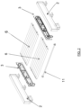
- the device as shown in the Figure 1 , consists of a bearing structure 2, composed of two parallel beams, and of a conveying system 3.
- the conveying system 3 comprises a set of mechanical elements located on or integrated into each of the beams of the bearing structure 2 , which allow the movement of at least two movable frames 6 located between the two beams.
- These mobile frames 6 can serve as a support for handling pallets, for example, in particular pallets of standard dimensions such as European pallets (EPAL).
- the supporting structure 2 can either be placed on the ground or separated from it by feet 21 of variable height depending on the intended application.
- the two parallel beams of the bearing structure 2 are independent or interconnected.
- the dimensioning and the embodiment of the bearing structure 2 are determined by the type of application envisaged and by the size and weight of the elements to be supported.
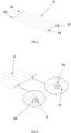
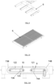
- FIG. 3 , 9 and 10 describe, by way of example and not exhaustive, several possible execution principles for mobile frames 6. These are either essentially full ( Figure 3 And 10 ), either hollowed out, openwork or slatted ( Figure 9 ), which allows them to support and move various types of pallets.
- Figure 9 in particular illustrates an alternative embodiment of a movable frame 6, open on one of its long sides and intended to easily receive several standardized pallets, such as euro-pallets for example. The opening along one of the long sides allows the removal or removal of the pallets by an automatically moving robot type vehicle (AGV).
- AGV automatically moving robot type vehicle
- FIG. 10 illustrates a mobile frame 6 in the form of a table with crenellated combs such as that used in laser cutting machines to receive the sheets to be cut.
- the conveying system 3 of the permutator 1 of the present invention operates in a closed loop, as detailed below, so as to be able to invert the position of the mobile frames 6 in a few seconds.
- the conveyor is of the "above/below” or “return below” type, that is to say that, when there are at least two mobile frames 6, one is in the high position and the another in the low position, and these exchange their positions via a displacement operated by the conveying system 3 according to a so-called double rail or staggered rail system.
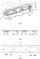
- the conveying system 3 comprises, as explained above, a set of mechanical elements for setting the mobile frames 6 in motion, namely a set of sprockets 4, 41-49 and transmission chains 51-53, as well as two conveyor chains 5 ( Figure 5 And 6 ).
- the sprockets 4, 41-49 and chains 5, 51-53 form an undercarriage making it possible to carry out the parallel and simultaneous displacement of the mobile frames 6, the conveyor chains 5 playing a driving role for the mobile frames 6 such that explained later.
- the sprockets 4, 41-49 and chains 5, 51-53 can advantageously be replaced by pulleys and toothed belts.
- Each mobile frame 6 is provided with running and guide rollers 8, 81 to 84 as represented on the Figures 3 and 4 . These are located on the lateral sides of the movable frame 6 and cooperate with guide grooves 7.
- the "lateral" sides of each movable frame 6 are considered to be the sides parallel to the beams of the supporting structure 2 and the "transverse" sides as being those perpendicular to these beams.
- Mobile rollers 8 operate in pairs, a first pair (“front” pair) with rollers 81 and 82 and a second pair (“rear” pair) with rollers 83 and 84 ( Figure 3 ).
- the "front” part of the system is considered to be the part located on the side where the frame is in the advanced position when it is in the high position (therefore just before starting its descent in the low position ), and vice versa for the “rear” part.
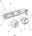
- the guide grooves 7, as shown in the Figure 8 constitute a raceway for the rollers 8 of the movable frames 6.
- An essential element of the invention resides in the fact that the first pair of rollers 81 and 82 and the second pair of rollers 83 and 84 of the same movable frame 6 will take a different path within the guide grooves 7, in order to keep the two movable frames 6 horizontal during their entire movement. The two different paths are taken through a system of switches as explained below.
- groove 71 corresponds to an upper horizontal displacement plane.
- Groove 72 corresponds to a lower horizontal displacement plane.
- the semi-circular grooves 73A, 73B allow downward movement from the upper plane to the lower plane while the semi-circular grooves 74A, 74B allow upward movement from the lower plane to the upper plane.
- the raceways of the two pairs of rollers 8 are partially common on the horizontal parts but different at the level of the semi-circular grooves, which allows the upward and downward movements of the mobile frames 6.
- the first pair of rollers 81 and 82 will take an external path 73B for the descent and an internal path 74A for the ascent, while the second pair of rollers will take an internal path 73A for the descent and an external path 74B for the ascent.
- This can obviously be done in the opposite way, this is an example for the proper understanding of the present invention, as are the definitions of the "front" and “rear” parts, which depend on the direction of rotation of the rollers 8 on the closed loop, which can of course be reversed. Thanks to this move of the type with staggered rails, a parallel movement between the two mobile frames 6 is constantly maintained.
- a small vertical separation between the two horizontal levels is preferable but depends on the type of application. For example, a distance of 20 to 30 cm between the horizontal planes of the two mobile frames 6 can be considered, preferably with a distance of 24 cm, or more if necessary.
- the system is provided with a system of switches, for example a set of cam-bridges 12, 121-123 as illustrated by the Figure 5 And 11A to 11H .
- a system of switches for example a set of cam-bridges 12, 121-123 as illustrated by the Figure 5 And 11A to 11H .
- the operation of an example switch system is described in detail in the next section.
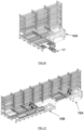
- the mobile frames 6 can be more than two in number. In the case shown, it is an embodiment of a permutator with three mobile frames 6.
- the principle of the invention remains identical, namely a conveying system 3 with chains, pinions and system of switches to correctly direct the pairs of "front” and “rear” rollers of each mobile frame 6. The number of mobile frames 6 can thus be multiplied.
- a pair of rollers for example the second pair of rollers 83, 84 comprises an overhanging axis 9, allowing the rollers to be supported by the pinions 4 during displacement movements in the semi-circular grooves 73A and 74B connecting the two horizontal movement planes.
- This is achievable thanks to the fact that the various pinions 4 are located inside each of the aforementioned semicircles, the toothed wheels of the pinions 4 coinciding with the grooves 73A and 74B in a semicircle (see Figure 5 And 6 ).
- the first pair of rollers 81, 82 has for its part an extended axis 10, which allows both the rollers to be supported by the pinions 4 during displacement movements in the grooves 73B and 74A in a semicircle connecting the two horizontal movement planes, but also to link them to the conveyor chains 5 located on either side on the other side of the permutator 1.
- the extended shaft 10 and the projecting shaft 9 can be located either on the rollers of the first or the second pair, depending on the position of the conveyor chains relative to the sprockets.
- the extended axis 10 is longer than the projecting axis 9.
- FIG. 5 Detailed views of the Figure 5 illustrate the principle of connection of the rollers 81, 82, 10 to the conveyor chain 5 as well as the principle of accompanying the rollers 83, 84, 9 by the sprockets 4 in the upward and downward movements of the mobile frame 6.
- the motor shaft 11 simultaneously drives the sets of pinions located on either side of the permutator 1.
- the sprockets of the motor shaft 49 drive by the chain 51 those of the shaft 111.
- the corresponding pinion 41 drives by the chain 52 the pinions of the shaft 112.
- the pinion 44 in turn drives the pinion 45 of the shaft 113 itself connected by the chain 53 to the pinion 48 of the shaft 114.
- FIGS. 11A to 11F illustrate, according to a non-limiting embodiment of the invention, a complete permutation cycle of a mobile frame 6.
- a switch system here illustrated by a set of cam-bridges (or simply cams) 121-123 , allows the rollers 8 to be guided in the appropriate grooves 7 in order to allow each mobile frame 6 to remain horizontal.
- the cam 122 is in the lowered position (horizontal right part, oblique left part) to prevent the roller 10 (extended axis of the first pair of rollers 81, 82) from following the first descending groove 73A that it encounters.
- the cam 121 is also in a horizontal position to allow the roller 9 (axis projecting from the second pair of rollers 83, 84) to cross the opening formed by the meeting of the rising groove 74A and the upper horizontal groove 71.
- the roller 10 meets the oblique part of the cam 122 (on the left) and tilts the latter to the horizontal causing, at the same time, the raising of the right part of the cam 122.
- the roller 9 can thus s Engage in the descending groove 73A, the opening being released.
- FIG. 11C shows the rollers 10 and 9 engaged in the two respective descending grooves 73B and 73A.
- the roller 10 driven by the chain 5 to which it is bonded, opens into the groove corresponding to the lower plane of movement. It is the same for the roller 9 which is supported at the end of its travel by the cam 123.
- roller 10 is the "front” roller and the roller 9 the “rear” roller when the movable frame 6 is in the upper plane of movement, the front/rear position of the rollers 10 and 9 is reversed. when the mobile frame is in the lower plane of movement.
- the mobile frame continues its movement in the lower horizontal groove.
- the roller 10 meets the cam 123 and raises it to continue its course.
- the rollers 9 and 10 are engaged in the upper displacement groove 71.
- the cams 122 and 121 are again in the horizontal position.
- all the cams have returned to their initial position either by gravity or by means of an ad hoc mechanism.
- the volume of the cam 122 is hollowed out (more importantly) at the level of its oblique side to the left, which allows it to resume its initial position by gravity as soon as the roller 10 or 9 has passed.
- the permutator according to the present invention is compatible with many equipments, as explained below. This thus makes it useful in performing multiple tasks.
- the pallet changer 1 can be equipped with mobile frames 6 open on one of the sides perpendicular to the beams of the supporting structure (see also Picture 9 ). This allows different types of automated vehicles to have easy access to the pallets, including automated vehicles without forks which can slip under the pallet and lift it out of its housing.
- the pallet changer 1 is advantageously designed to be integrated into the storage towers 13 of a linear automated warehouse (see Picture 14 ).
- the beams of the supporting structure 2 of the pallet changer 1 are then sized to receive the load represented by the dead weight of the storage tower 13 plus the weight of the pallets loaded with their contents.
- the height of ladders of the storage towers 13 associated with a permutator 1 is reduced by the height of the latter so that they are aligned with the height of the standard towers of the store.
- the lateral crosspieces 2A of the mobile frames 6 of the permutator 1 are aligned on the profiles 2B supporting the pallets with claws 2C specific to the automated stores, so that the pallets with claws 2C can be transferred from the permutator 1 to one of the stalls of the store and vice versa.
- This moving operation is carried out by a pallet elevator circulating parallel to the storage towers.
- the symmetry of the beam forming the bearing structure of the permutator 1 makes it possible to duplicate the mechanism when several permutators 1 are juxtaposed, while respecting the alignment with the ladders of the towers of the automated store.
- the structure of the permutator 1 can be adapted with a view to integrating a track 14 and a robot 15, as represented on the Figure 16A and 16B .
- this configuration could be particularly interesting in the case of a 16A folding (micro)cell by giving it practically unlimited operating autonomy without assistance and an operating rate maximized by the presence of the permutator 1.
- the robotic cell 16 is connected by two permutators 1 to two of the towers 13 of the automated store. This double connection makes it possible to automatically introduce the parts to be folded into the cell and to deposit the folded parts on the second permutator 1 according to a pre-established nesting and stacking program.
- the pallet changer of the present invention is that it is modular and adaptable to a whole series of equipment, multiplying the time savings and the productivity of the production workshops.
- a permutator configuration 1 comprising three movable frames 6 (as illustrated in Figure 12 And 18 ) is a particularly advantageous mode of the invention. Indeed, this mode makes it possible to swap three elements simultaneously in a single operation lasting a few seconds. It is particularly interesting when the process is broken down into three phases. This is the case, for example, for 16B laser cutting machines where the steps of the process, namely cutting, evacuation of the cut parts and preparation of the new sheet, are often carried out successively and not simultaneously, thus inducing waiting times during which the machine is not productive.
- This configuration is also distinguished by its great simplicity of design as well as its compactness.
- the third entry can be used by way of example and not exhaustively to introduce into the cell 16A tools shared between several bending cells 16A connected to the store, specific tools dedicated to a customer, elements making it possible to optimize the stacking of the bent parts , large grippers, etc.
- the example shown on the Picture 18 And 19 shows an installation combining on the one hand a permutator 1 equipped with three mobile frames 6 (such as that illustrated in Picture 12 ) integrated with a cutting laser, and on the other hand three permutators 1 each equipped with two mobile frames 6 integrated into the towers 13 of an automated store.
- the installation further comprises at least one robot 15 moving on a track 14.
- This illustration highlights the compactness of the laser and its servo system consisting of a permutator 1 with three mobile frames and a robot mounted on a track.
- the robot 15 will pick up a new sheet from the first permutator 1 of the magazine and place it on the laser table located opposite. Then, he will take the parts cut out during the previous sequence and deposit them on the second permutator 1 of the magazine. Once this work is completed, the robot 15 will evacuate the sheet metal skeleton to the third permutator 1 of the store.
- the different grippers necessary for the robot 15 to carry out the handling of parts of various sizes as well as skeletons can for example be advantageously arranged on the external faces of the storage towers 13 of the store.
- the robot 15 is sized so that its extension length enables it to reach the places farthest from the laser tables or from the pallets of the permutators 1 of the store.
- the load-bearing structure of the permutator can be used to support the track and the robot. A variant with columns and suspended track is also possible (not shown).
- cell 16A illustrates a combination of different supply flow management modes for cell 16A.
- cell 16A is equipped with a changeover switch 1 dedicated to europallets (EPAL), facing the workshop and making it possible to manage part of the incoming and outgoing flows using an assisted lift 17 or an automatically guided and programmed vehicle (AGV).
- EPAL europallets
- AGV automatically guided and programmed vehicle
- FIG. 21 illustrates how it would be possible to arrange the cutting cells 16B, such as lasers or punching machines, as well as the bending cells 16A around a linear automated store in order to connect all the machines together and thus increase the operational autonomy without assistance and the operating rate of the production tool as a whole.
- cutting cells 16B such as lasers or punching machines
Abstract
Un permutateur (1) de palettes comprenant :- une structure portante (2) ;- au moins deux cadres mobiles (6) aptes, en utilisation, à porter chacun une palette (18), chaque cadre mobile (6) comprenant une première paire de galets (81, 82) et une seconde paire de galets (83, 84) sur ses côtés latéraux ;- un système de convoyage (3) situé sur la structure portante (2) permettant le déplacement des cadres mobiles (6) et relié à un arbre moteur (11) ;- un ensemble de rainures de guidage (71, 72, 73A, 73B, 74A, 74B) formant une boucle fermée à rails séparés et un chemin de guidage pour chaque cadre mobile (6), comprenant un premier chemin et un second chemin, lesdites rainures (71, 72, 73A, 73B, 74A, 74B) accueillant les galets (81, 82, 83, 84) des cadres mobiles (6) ;- un système d'aiguillages à cames (12, 121, 122, 123) des paires de galets (81, 82 ; 83, 84) dans les rainures de guidage (71, 72, 73A, 73B, 74A, 74B) ;le système d'aiguillages à cames (121, 122, 123) étant apte à guider, en utilisation, les paires de galets (81, 82, 10 ; 83, 84, 9) de sorte que la première paire (81, 82, 10) emprunte le premier chemin et la seconde paire (83, 84, 9) emprunte le second chemin de manière à déplacer les cadres mobiles (6) le long de la boucle fermée tout en restant en permanence parallèles entre eux horizontalement et orientés dans le même sens.A pallet changer (1) comprising:- a supporting structure (2);- at least two movable frames (6) capable, in use, of each carrying a pallet (18), each movable frame (6) comprising a first pair of rollers (81, 82) and a second pair of rollers (83, 84) on its lateral sides;- a conveying system (3) located on the bearing structure (2) allowing the movement of the mobile frames (6) and connected to a motor shaft (11);- a set of guide grooves (71, 72, 73A, 73B, 74A, 74B) forming a closed loop with separate rails and a guide path for each movable frame (6), comprising a first path and a second path, said grooves (71, 72, 73A, 73B, 74A, 74B) receiving the rollers (81, 82, 83, 84) of the movable frames (6); - a cam switch system ( 12, 121, 122, 123) pairs of rollers (81, 82; 83, 84) in the guide grooves (71, 72, 73A, 73B, 74A, 74B); the cam switch system (121, 122, 123) being able to guide, in u use, the pairs of rollers (81, 82, 10; 83, 84, 9) so that the first pair (81, 82, 10) take the first path and the second pair (83, 84, 9) take the second path so as to move the movable frames (6) along of the closed loop while remaining permanently parallel to each other horizontally and oriented in the same direction.
Description
La présente invention se rapporte au domaine des convoyeurs automatisés. En particulier, la présente invention concerne un convoyeur de palettes en entrée/sortie d'un magasin automatisé à tours.The present invention relates to the field of automated conveyors. In particular, the present invention relates to a pallet conveyor at the entrance/exit of an automated lathe store.
Dans les ateliers de production, le taux d'exploitation des machines-outils est souvent pénalisé par les périodes d'interruption du travail consécutives aux opérations de manutention liées à l'approvisionnement en pièces brutes à façonner et à l'évacuation des pièces façonnées. La présente analyse s'est particulièrement focalisée sur le cas des presses-plieuses manuelles et/ou automatisées, mais celle-ci peut être adaptée à d'autres domaines imposant des flux d'approvisionnement et d'évacuation de différentes matières, dont l'optimisation permet d'augmenter le taux d'exploitation des outils de production.In production workshops, the operating rate of machine tools is often penalized by periods of work interruption following handling operations related to the supply of raw parts to be shaped and the evacuation of shaped parts. This analysis has particularly focused on the case of manual and/or automated press brakes, but it can be adapted to other areas requiring supply and evacuation flows of different materials, including optimization makes it possible to increase the operating rate of production tools.
Plusieurs cas de figure sont observables lors de l'approvisionnement et l'évacuation des pièces. Dans un premier cas, la presse-plieuse est desservie par un opérateur chargé également des manutentions, à savoir, l'approvisionnement de son poste de travail en pièces à plier et l'évacuation des pièces pliées dont la volumétrie plus importante conduit assez rapidement à une saturation de l'espace disponible et à la nécessité de libérer cet espace pour y fournir de nouvelles pièces à fabriquer. L'inconvénient de cette situation réside dans le fait que la machine n'est pas productive pendant les périodes de temps où l'opérateur est occupé à des tâches de manutention. En outre, l'opérateur doit parfois attendre qu'un engin de levage, généralement un élévateur partagé entre plusieurs postes, soit disponible, ce qui accroît encore les temps d'improductivité de la machine et de son opérateur.Several scenarios can be observed during the supply and removal of parts. In a first case, the press brake is served by an operator also responsible for handling, namely, supplying his workstation with parts to be bent and removing the bent parts, the larger volume of which leads fairly quickly to a saturation of the available space and the need to free up this space to provide new parts to be manufactured. The disadvantage of this situation is that the machine is not productive during periods of time when the operator is busy with handling tasks. In Furthermore, the operator must sometimes wait for a lifting device, generally a lift shared between several positions, to become available, which further increases the downtime of the machine and its operator.
Dans un second cas, les opérations de manutention (approvisionnement et évacuation) sont assurées par un manutentionnaire desservant plusieurs postes de travail. Les opérateurs-machines peuvent ainsi se concentrer totalement sur leur tâche spécifique. Dans ce cas de figure, les périodes de temps où la machine est improductive sont déterminées, d'une part, par le temps d'attente de la disponibilité du manutentionnaire qui peut parfois être occupé sur un autre poste de travail et d'autre part, par le temps nécessaire au manutentionnaire pour procéder à l'enlèvement et au restockage des palettes à évacuer, ou encore, pour évacuer une palette d'approvisionnement vide et la remplacer par une nouvelle palette de pièces à façonner.In a second case, the handling operations (supply and evacuation) are carried out by a handler serving several workstations. Machine operators can thus fully concentrate on their specific task. In this case, the periods of time when the machine is unproductive are determined, on the one hand, by the waiting time of the availability of the handler who can sometimes be occupied on another workstation and on the other hand , by the time necessary for the handler to remove and restock the pallets to be evacuated, or even to evacuate an empty supply pallet and replace it with a new pallet of parts to be shaped.
Dans un troisième cas, la presse-plieuse est robotisée et on parle dans ce cas d'une cellule de pliage. Une partie de la surface de la cellule est dédiée au stockage des pièces à plier généralement disposées sur des palettes. Une autre partie de la surface de la cellule est dédiée aux palettes destinées à recevoir les pièces après pliage. Comme dans le cas de figure précédent, la productivité de la cellule sera dépendante de la disponibilité du manutentionnaire et des temps de manutentions. Le degré d'autonomie de la cellule de pliage robotisée reste donc dépendant de la présence d'une assistance humaine ponctuelle et récurrente à la fois.In a third case, the press brake is robotized and in this case we speak of a bending cell. Part of the surface of the cell is dedicated to the storage of parts to be bent, generally placed on pallets. Another part of the surface of the cell is dedicated to the pallets intended to receive the parts after bending. As in the previous scenario, the productivity of the cell will depend on the availability of the handler and the handling times. The degree of autonomy of the robotic bending cell therefore remains dependent on the presence of occasional and recurrent human assistance.
A l'heure actuelle, il existe dès lors un réel intérêt d'optimiser le taux d'exploitation des postes de travail, par la mise à disposition instantanée de ce qui est requis pour leur fonctionnement. En effet, la productivité est directement liée à la mise à disposition des éléments dont les postes de travail ont besoin.At the present time, there is therefore a real interest in optimizing the rate of exploitation of workstations, by the instantaneous availability of what is required for their operation. Indeed, productivity is directly linked to the availability of the elements that workstations need.
Les documents
Le document
La présente invention a pour but de fournir un convoyeur de palettes servant à permuter simultanément au moins deux palettes, l'une prenant la place de l'autre ou de celle qui la suit et inversement pour permettre une réelle automatisation productive des flux.The object of the present invention is to provide a pallet conveyor used to simultaneously switch at least two pallets, one taking the place of the other or of the one that follows it and vice versa to allow real productive automation of the flows.
Un des buts principaux de la présente invention est de permettre la permutation de palettes sans changer l'orientation de la charge tout au long de l'opération.One of the main objects of the present invention is to allow the permutation of pallets without changing the orientation of the load throughout the operation.
L'invention vise en particulier à optimiser le taux d'exploitation d'un poste de travail par la mise à disposition instantanée de ce qui est requis pour son fonctionnement. Les flux entrant(s) et sortant(s) du poste de travail peuvent ainsi être toujours dédoublés d'un stock tampon garantissant un fonctionnement avec une interruption limitée de la machine et de son opérateur (ou de la cellule dans le cas où la machine est robotisée).The invention aims in particular to optimize the utilization rate of a workstation by the instantaneous provision of what is required for its operation. Flows entering and leaving the workstation can thus always be duplicated by a buffer stock guaranteeing operation with limited interruption of the machine and its operator (or of the cell in the case where the machine is robotized).
La présente invention a également pour but de fournir une solution permettant d'améliorer la flexibilité de la tâche des manutentionnaires, ou des systèmes de gestion automatique des flux. Le travail du manutentionnaire (ou de l'automate) est rendu plus flexible car il peut mieux prioriser les flux de manutention entre les différents postes de travail qu'il dessert.The object of the present invention is also to provide a solution making it possible to improve the flexibility of the task of handlers, or automatic flow management systems. The work of the handler (or the automaton) is made more flexible because he can better prioritize the handling flows between the different workstations he serves.
Un autre but poursuivi par l'invention est de fournir un convoyeur de palettes simple et adaptable à une grande variété d'équipements. En effet, celui-ci doit être combinable par exemple avec différents types de véhicules automatisés, et être conçu également pour s'intégrer aux tours de stockage d'un magasin automatisé linéaire ou à un laser de découpe.Another object pursued by the invention is to provide a pallet conveyor that is simple and adaptable to a wide variety of equipment. Indeed, it must be combinable, for example, with different types of automated vehicles, and also be designed to integrate with the storage towers of a linear automated warehouse or with a cutting laser.
Un premier aspect de la présente invention se rapporte à un permutateur de palettes comprenant :
- une structure portante ;
- au moins deux cadres mobiles aptes, en utilisation, à porter chacun une palette, chaque cadre mobile comprenant une première paire de galets et une seconde paire de galets sur ses côtés latéraux ;
- un système de convoyage situé sur la structure portante permettant le déplacement des cadres mobiles et relié à un arbre moteur ;
- un ensemble de rainures de guidage formant une boucle fermée à rails séparés et un chemin de guidage pour chaque cadre mobile, comprenant un premier chemin et un second chemin, lesdites rainures accueillant les galets des cadres mobiles ;
- un système d'aiguillages à cames des paires de galets dans les rainures de guidage ;
- a supporting structure;
- at least two movable frames capable, in use, of each carrying a pallet, each movable frame comprising a first pair of rollers and a second pair of rollers on its lateral sides;
- a conveyor system located on the supporting structure allowing the movement of the mobile frames and connected to a motor shaft;
- a set of guide grooves forming a closed loop with separate rails and a guide path for each movable frame, comprising a first path and a second path, said grooves accommodating the rollers of the movable frames;
- a cam switch system of pairs of rollers in the guide grooves;
Selon des formes d'exécution préférées de l'invention, le permutateur de palettes comprend en outre une des caractéristiques suivantes, ou une combinaison appropriée de celles-ci :
- la structure portante comprend deux poutres parallèles, le système de convoyage et l'ensemble de rainures de guidage étant répartis de manière symétrique sur ou dans chacune des poutres, de sorte que les cadres mobiles sont déplacés entre les deux poutres par le système de convoyage;
- le système de convoyage comprend une pluralité de pignons et de chaînes de transmission, ou alternativement une pluralité de poulies et courroies crantées, pour mettre en mouvement les deux cadres mobiles via deux chaînes de convoyage situées de part et d'autre des cadres mobiles, de sorte que les cadres mobiles sont déplacés à l'aide de galets mobiles roulant à l'intérieur des rainures de guidage ;
- le système d'aiguillages comprend une pluralité de cames permettant de guider les première et seconde paires de galets respectivement dans les premier et second chemins des rainures de guidage ;
- les rainures de guidages comprennent une rainure correspond à un plan de déplacement horizontal supérieur, une rainure correspond à un plan de déplacement horizontal inférieur, deux rainures en demi-cercle permettant le déplacement descendant du plan supérieur au plan inférieur, et deux rainures en demi-cercle permettent le déplacement montant du plan inférieur au plan supérieur, lesdites rainures définissant les deux chemins précités, lesquels ont une forme oblongue et sont décalés horizontalement l'un par rapport à l'autre ;
- les galets de la première paire de galets comprennent un axe prolongé permettant à la fois à un jeu de pignons de supporter lesdits galets lors de leur déplacement dans les rainures en demi-cercle reliant les deux plans de déplacement horizontaux, et également de liaisonner lesdits galets aux chaînes de convoyage ;
- les galets de la deuxième paire de galets comprennent un axe débordant, permettant à un jeu de pignons de supporter lesdits galets lors de leur déplacement dans les rainures en demi-cercle reliant les deux plans de déplacement horizontaux ;
- les chemins de roulement des deux paires de galets de chaque cadre mobile ont une partie commune au niveau des plans de déplacement horizontal supérieur et inférieur et sont distincts au niveau des rainures en demi-cercle permettant les déplacements montant et descendant des cadres mobiles ;
- les cadres mobiles sont pleins ou ajourés.
- the supporting structure comprises two parallel beams, the conveyor system and the set of guide grooves being distributed symmetrically on or in each of the beams, so that the frames mobiles are moved between the two beams by the conveying system;
- the conveying system comprises a plurality of sprockets and transmission chains, or alternatively a plurality of pulleys and toothed belts, to set the two movable frames in motion via two conveying chains located on either side of the movable frames, so that the movable frames are moved using movable rollers rolling inside the guide grooves;
- the switching system comprises a plurality of cams making it possible to guide the first and second pairs of rollers respectively in the first and second paths of the guide grooves;
- the guide grooves comprise a groove corresponding to an upper horizontal displacement plane, a groove corresponding to a lower horizontal displacement plane, two semi-circular grooves allowing downward displacement from the upper plane to the lower plane, and two semi-circular grooves circle allow the upward movement from the lower plane to the upper plane, said grooves defining the two aforementioned paths, which have an oblong shape and are offset horizontally relative to each other;
- the rollers of the first pair of rollers comprise an extended axis allowing both a set of pinions to support said rollers during their movement in the semi-circular grooves connecting the two horizontal planes of movement, and also to link said rollers conveyor chains;
- the rollers of the second pair of rollers comprise a protruding axis, allowing a set of pinions to support said rollers during their movement in the semi-circular grooves connecting the two horizontal planes of movement;
- the raceways of the two pairs of rollers of each mobile frame have a common part at the level of the upper and lower horizontal displacement planes and are distinct at the level of the grooves in semi-circle allowing the up and down movements of the mobile frames;
- the mobile frames are solid or perforated.
L'invention se rapporte également à l'utilisation du permutateur de palettes décrit ci-dessus, pour la mise en oeuvre du cycle de mouvements suivants relatifs à l'échange des positions initiales d'un premier cadre mobile et d'un second cadre mobile, aptes à supporter chacun une palette :
- au début du cycle, le système de convoyage est activé par la mise en rotation de l'arbre moteur lorsque le premier cadre mobile est en position sur le plan de déplacement horizontal supérieur, chaque galet de roulement avant ayant son axe prolongé entraîné par la chaîne de convoyage et apte à s'engrener dans les pignons lors des mouvements de déplacement dans les rainures en demi-cercle reliant les deux plans de déplacement horizontaux ; et chaque galet de roulement arrière ayant son axe débordant apte à s'engrener dans les pignons lors des mouvements de déplacement dans les rainures en demi-cercle reliant les deux plans de déplacement horizontaux ;
- sous l'effet de l'entraînement, le galet de roulement avant arrive au croisement de la rainure horizontale supérieure et de la première rainure descendante ;
- une première came se trouvant à ce croisement étant en position abaissée, avec une partie droite suivie d'une partie oblique, le galet de roulement avant reste guidé dans la rainure horizontale supérieure et ensuite dans la seconde rainure descendante grâce au pignon, la rencontre du galet avec la partie oblique de la première came entraînant le relèvement de ladite came, la partie oblique basculant à l'horizontale et la partie droite étant relevée, libérant le passage dans la première rainure descendante pour le galet de roulement arrière ;
- une deuxième came se trouvant au croisement de la rainure horizontale supérieure avec la première rainure montante en position horizontale, le galet de roulement arrière franchit l'ouverture vers la première rainure montante et poursuit son chemin dans la rainure horizontale supérieure ;
- la première came étant relevée, le galet de roulement arrière est guidé dans la première rainure descendante ;
- lorsque le galet de roulement avant arrive au niveau de la rainure horizontale inférieure, il continue à être entraîné plus loin dans cette rainure par la chaîne de convoyage alors que, simultanément, le galet de roulement arrière arrive au niveau de la troisième came en fin de course dans la première rainure descendante, ladite troisième came étant en position abaissée, ce qui laisse passer le galet arrière ;
- le cadre mobile poursuit son déplacement dans la rainure horizontale inférieure et le galet de roulement avant soulève la troisième came pour continuer sa course ;
- le galet de roulement arrière supporté par le pignon est entraîné dans la seconde rainure montante et le galet de roulement avant supporté par le pignon est entraîné dans la première rainure montante, de manière à effectuer le transfert du plan de déplacement inférieur au plan de déplacement supérieur ;
- le galet de roulement avant débouche dans la rainure horizontale supérieure en soulevant la deuxième came et simultanément avec le galet de roulement arrière ;
- le premier cadre mobile revient à sa position de départ dans la rainure horizontale supérieure et les deuxième came et première came sont soit en position abaissée pour le cycle suivant grâce à la gravité, soit sont ramenées en position abaissée par un mécanisme ad hoc ;
- les mouvements sont similaires pour le second cadre mobile, celui-ci se trouvant au début du cycle en position sur le plan de déplacement horizontal inférieur.
- at the beginning of the cycle, the conveying system is activated by the rotation of the motor shaft when the first moving frame is in position on the upper horizontal plane of movement, each front roller having its extended axis driven by the chain conveying and capable of meshing in the pinions during displacement movements in the semi-circular grooves connecting the two horizontal displacement planes; and each rear roller having its protruding axis capable of meshing in the pinions during displacement movements in the semi-circular grooves connecting the two horizontal planes of displacement;
- under the effect of the drive, the front roller arrives at the intersection of the upper horizontal groove and the first descending groove;
- a first cam located at this intersection being in the lowered position, with a straight part followed by an oblique part, the front roller remains guided in the upper horizontal groove and then in the second descending groove thanks to the pinion, the meeting of the roller with the oblique part of the first cam causing the raising of said cam, the oblique part tilting to the horizontal and the straight part being raised, freeing the passage in the first descending groove for the rear running roller;
- a second cam located at the intersection of the upper horizontal groove with the first rising groove in the horizontal position, the rear roller crosses the opening towards the first rising groove and continues its path in the upper horizontal groove;
- the first cam being raised, the rear roller is guided in the first descending groove;
- when the front roller arrives at the level of the lower horizontal groove, it continues to be driven further into this groove by the conveyor chain while, simultaneously, the rear roller arrives at the level of the third cam at the end of stroke in the first descending groove, said third cam being in the lowered position, which lets the rear roller pass;
- the mobile frame continues its movement in the lower horizontal groove and the front roller raises the third cam to continue its travel;
- the pinion-supported rear roller is driven in the second rising groove, and the pinion-supported front roller is driven in the first rising groove, so as to transfer from the lower travel plane to the upper travel plane ;
- the front running roller opens into the upper horizontal groove by lifting the second cam and simultaneously with the rear running roller;
- the first mobile frame returns to its starting position in the upper horizontal groove and the second cam and first cam are either in the lowered position for the next cycle thanks to gravity, or are returned to the lowered position by an ad hoc mechanism;
- the movements are similar for the second movable frame, the latter being at the start of the cycle in position on the lower horizontal displacement plane.
Un autre aspect de la présente invention concerne une tour de stockage de magasin automatisé à tour ou vertical, comprenant, intégré à sa base, un permutateur de palettes tel que décrit ci-dessus.Another aspect of the present invention relates to an automated tower or vertical magazine storage tower, comprising, integrated into its base, a pallet changer as described above.
Encore un autre aspect de l'invention concerne une installation de fabrication automatisée, comprenant un magasin automatisé ainsi qu'au moins une cellule de pliage et/ou une cellule de découpe laser, ledit magasin automatisé comprenant au moins une tour de stockage telle que décrite ci-dessus.Yet another aspect of the invention relates to an automated manufacturing facility, comprising an automated warehouse as well as at least one folding cell and/or one laser cutting cell, said automated store comprising at least one storage tower as described above.
-
La
figure 1 représente une vue générale en trois dimensions d'une forme d'exécution du convoyeur permutateur de palettes selon la présente invention, le système comprenant en l'espèce deux cadres mobiles.Therefigure 1 shows a general view in three dimensions of an embodiment of the pallet changer conveyor according to the present invention, the system comprising in this case two movable frames. -
La
figure 2 représente une vue en éclaté du permutateur de lafigure 1 .Therefigure 2 shows an exploded view of the permutator of thefigure 1 . -
La
figure 3 représente une vue en trois dimensions d'un premier exemple de cadre mobile du convoyeur de palettes selon la présente invention.Therepicture 3 -
La
figure 4 représente une vue détaillée des galets du cadre mobile de lafigure 3 .Therefigure 4 shows a detailed view of the rollers of the mobile frame of thepicture 3 -
La
figure 5 représente une vue de détail du premier exemple de cadre mobile combiné au système de convoyage du convoyeur permutateur selon la présente invention.Therefigure 5 shows a detail view of the first example of a mobile frame combined with the conveyor system of the permutator conveyor according to the present invention. -
La
figure 6 est une vue de lafigure 5 avec le détail des repères de référence.Therefigure 6 is a view of thefigure 5 with detailed reference marks. -
La
figure 7 représente une vue en plan d'un exemple de système de transmission du convoyeur permutateur selon la présente invention.Therefigure 7 shows a plan view of an exemplary interchange conveyor transmission system according to the present invention. -
La
figure 8 représente une vue en élévation des différents types de rails d'un exemple de système de convoyage du convoyeur permutateur selon la présente invention.Therefigure 8 shows an elevational view of the different types of rails of an example of a conveyor system of the switching conveyor according to the present invention. -
La
figure 9 représente un deuxième exemple de cadre mobile selon l'invention, celui-ci étant ouvert sur un côté afin d'y déposer facilement une palette à l'aide d'un chariot élévateur par exemple.Therefigure 9 represents a second example of a mobile frame according to the invention, the latter being open on one side in order to easily place a pallet thereon using a forklift for example. -
La
figure 10 représente un troisième exemple de cadre mobile du convoyeur selon l'invention.Therefigure 10 represents a third example of a movable frame of the conveyor according to the invention. -
Les
figures 11A à 11H représentent les étapes successives d'un cycle de permutation complet d'un cadre mobile avec différents aiguillages, selon un mode d'exécution de la présente invention.THEfigures 11A to 11H represent the successive steps of a complete permutation cycle of a moving frame with different switches, according to an embodiment of the present invention. -
La
figure 12 représente une vue en trois dimensions d'un permutateur de palettes selon l'invention, comprenant trois cadres mobiles.Therefigure 12 shows a three-dimensional view of a pallet changer according to the invention, comprising three movable frames. -
La
figure 13 représente une vue en trois dimensions d'un permutateur de palettes selon l'invention avec trois jeux de deux cadres mobiles, les cadres mobiles étant ouverts d'un côté afin d'y poser facilement une palette à l'aide un chariot élévateur.Therefigure 13 shows a three-dimensional view of a pallet changer according to the invention with three sets of two movable frames, the movable frames being open on one side in order to easily place a pallet thereon using a forklift. -
La
figure 14 représente une vue en trois dimensions d'un permutateur de palettes selon l'invention avec deux cadres mobiles, associé à une tour de stockage d'un magasin automatisé linéaire.Therefigure 14 shows a three-dimensional view of a pallet changer according to the invention with two mobile frames, associated with a storage tower of a linear automated store. -
La
figure 15 représente une vue de détail des éléments d'insertion d'un permutateur selon l'invention dans une tour de magasin automatisé.Therefigure 15 shows a detail view of the insertion elements of a permutator according to the invention in an automated store tower. -
Les
figures 16A et 16B représentent un segment de magasin automatisé dans lequel le poste de travail, une cellule de pliage par exemple, est connecté par un permutateur, respectivement deux permutateurs selon l'invention, aux tours du magasin.THEfigures 16A and 16B represent an automated store segment in which the workstation, a folding cell for example, is connected by a permutator, respectively two permutators according to the invention, to the towers of the store. -
La
figure 17 représente un segment de magasin automatisé dans lequel le poste de travail, une cellule de pliage par exemple, est connecté par trois permutateurs aux tours du magasin.Therefigure 17 represents an automated store segment in which the workstation, a bending cell for example, is connected by three switches to the towers of the store. -
La
figure 18 représente une vue en plan d'un exemple d'installation combinant, d'une part, un permutateur selon l'invention équipé de trois cadres mobiles, intégré à un laser de découpe et d'autre part, trois permutateurs selon l'invention équipés de deux cadres mobiles intégrés aux tours d'un magasin automatisé. L'installation comporte en outre un robot se déplaçant sur un track.Therefigure 18 shows a plan view of an example of an installation combining, on the one hand, a permutator according to the invention equipped with three movable frames, integrated with a cutting laser and, on the other hand, three permutators according to the invention equipped of two mobile frames integrated into the towers of an automated warehouse. The installation also includes a robot moving on a track. -
La
figure 19 représente une vue en trois dimensions de l'installation de lafigure 18 .Therefigure 19 shows a three-dimensional view of the installation of thefigure 18 . -
La
figure 20 représente une combinaison de différents modes de gestion des flux d'approvisionnement d'une cellule robotisée, pourvue d'un permutateur selon la présente invention.Therefigure 20 represents a combination of different supply flow management modes of a robotic cell, provided with a permutator according to the present invention. -
La
figure 21 représente différentes cellules robotisées agencées autour d'un magasin automatisé linéaire afin de connecter l'ensemble des machines entre elles et augmenter ainsi l'autonomie de fonctionnement sans assistance et le taux d'exploitation de l'outil de production dans son ensemble.Therefigure 21 represents different robotic cells arranged around a linear automated store in order to connect all the machines together and thus increase the autonomy of operation without assistance and the operating rate of the production tool as a whole.
La présente invention concerne un convoyeur permutateur de palettes, c'est-à-dire un système permettant de permuter simultanément au moins deux palettes, l'une prenant la place de l'autre ou de celle qui la suit sur le convoyeur et inversement, sans changer l'orientation de la charge afin de permettre une réelle automatisation des flux. Le convoyeur permutateur permet la création d'un stock tampon garantissant un fonctionnement de la production à interruptions limitées. Dans la suite de l'exposé, le convoyeur permutateur sera simplement désigné par permutateur.The present invention relates to a pallet swapping conveyor, that is to say a system making it possible to simultaneously swap at least two pallets, one taking the place of the other or of the one following it on the conveyor and vice versa, without changing the orientation of the load in order to allow a real automation of flows. The changeover conveyor allows the creation of a buffer stock guaranteeing production operation with limited interruptions. In the remainder of the description, the permutator conveyor will simply be referred to as a permutator.
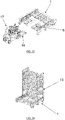
Le dispositif, tel qu'illustré sur la
La structure portante 2 peut être soit posée au sol ou écartée de celui-ci par des pieds 21 de hauteur variable selon l'application envisagée. Les deux poutres parallèles de la structure portante 2 sont indépendantes ou reliées entre elles. Le dimensionnement et le mode de réalisation de la structure portante 2 sont déterminés par le type d'application envisagée et par la taille et le poids des éléments à supporter.The supporting
Les
Le système de convoyage 3 du permutateur 1 de la présente invention fonctionne en boucle fermée, tel que détaillé ci-dessous, de manière à pouvoir intervertir la position des cadres mobiles 6 en quelques secondes. Le convoyeur est de type « dessus/dessous » ou « à retour en dessous », c'est-à-dire que, lorsqu'il y a au moins deux cadres mobiles 6, l'un se trouve en position haute et l'autre en position basse, et ceux-ci échangent leurs positions via un déplacement opéré par le système de convoyage 3 selon un système dit à double rail ou à rails décalés.The conveying
Le système de convoyage 3 comprend, tel qu'expliqué précédemment, un ensemble d'éléments mécaniques pour mettre en mouvement les cadres mobiles 6, à savoir un ensemble de pignons 4, 41-49 et de chaînes de transmission 51-53, ainsi que deux chaînes de convoyage 5 (
Chaque cadre mobile 6 est muni de galets de roulement et de guidage 8, 81 à 84 tels que représentés sur les
Les rainures de guidage 7, telles qu'illustrées sur la
Plus spécifiquement, les rainures de guidage 7 sont détaillés à la
Afin de permettre aux cadres mobiles 6 de suivre le chemin adéquat dans les rainures 7, le système est pourvu d'un système d'aiguillages, par exemple un ensemble de cames-ponts 12, 121-123 telles qu'illustrées par les
Comme représenté sur la
Tel qu'illustré de manière générale sur les
Les vues en détails de la
Comme représenté à la
La
Les
Sur la
Sur la
La
Sur la
On notera que, si le galet 10 est le galet « avant » et le galet 9 le galet « arrière » lorsque le cadre mobile 6 se trouve dans le plan de déplacement supérieur, la position avant/arrière des galets 10 et 9 s'inverse lorsque le cadre mobile se trouve dans le plan de déplacement inférieur.It will be noted that, if the
Sur la
Sur la
Sur la
Sur la
Dans les ateliers où les flux de manutention ne sont pas automatisés, la présence de permutateurs selon l'invention offrirait un double avantage. D'une part, les flux entrant(s) et sortant(s) du poste de travail seraient toujours dédoublés d'un stock tampon garantissant un fonctionnement pratiquement sans interruption de la machine et de son opérateur (ou de la cellule dans le cas où la machine est robotisée). D'autre part, le travail du manutentionnaire serait rendu plus flexible car ce dernier pourrait mieux prioriser les flux de manutention entre les différents postes de travail dont il a la charge.In workshops where the handling flows are not automated, the presence of permutators according to the invention would offer a double advantage. On the one hand, the flows entering and leaving the workstation would always be duplicated by a buffer stock guaranteeing practically uninterrupted operation of the machine and its operator (or of the cell in the case where the machine is robotized). On the other hand, the work of the handler would be made more flexible because the latter could better prioritize the handling flows between the different workstations for which he is responsible.
Déjà certains ateliers misent aujourd'hui sur l'automatisation des manutentions. L'approvisionnement des postes de travail ainsi que l'évacuation et le restockage des pièces façonnées sont ainsi de plus en plus assurés par des véhicules automatisés dont les déplacements sont entièrement programmés.Already some workshops are now relying on the automation of handling. The supply of workstations as well as the evacuation and restocking of shaped parts are thus increasingly ensured by automated vehicles whose movements are fully programmed.
Le permutateur selon la présente invention est compatible avec de nombreux équipements, tel qu'expliqué ci-dessous. Ceci le rend ainsi utile dans l'exécution de plusieurs tâches.The permutator according to the present invention is compatible with many equipments, as explained below. This thus makes it useful in performing multiple tasks.
Comme représenté sur la
Dans un mode d'exécution préféré de l'invention, le permutateur de palettes 1 est avantageusement conçu pour s'intégrer aux tours de stockage 13 d'un magasin automatisé linéaire (voir
Tel qu'illustré par la
Toujours selon l'invention, la structure du permutateur 1 peut être adaptée en vue de l'intégration d'un track 14 et d'un robot 15, comme représenté sur les
Une configuration de permutateur 1 comportant trois cadres mobiles 6 (comme illustré aux
Dans certains cas de figure, il pourrait s'avérer intéressant de prévoir une triple connexion d'une cellule robotisée 16A au magasin (voir
L'exemple représenté sur les
La
La
- 11
- Permutateur de palettesPallet switcher
- 22
- Structure portante du permutateurLoad-bearing structure of the permutator
- 2121
- Pied de poutrebeam foot
- 2A2A
- Traverse latérale de cadre mobileMovable frame side rail
- 2B2B
- Profil de supportSupport profile
- 2C2C
- Palette à becBeak pallet
- 33
- Système de convoyageconveyor system
- 44
- Pignons (références 41-49 pour les différents pignons)Sprockets (references 41-49 for the different sprockets)
- 55
- Chaîne de convoyageconveyor chain
- 51-5351-53
- Chaînes de transmissionChains of transmission
- 66
- Cadre mobile (références 61 et 62 également)Mobile frame (references 61 and 62 also)
- 77
- Rainure de guidage (références 71, 72, 73A, 73B, 74A, 74B pour les différentes rainures)Guide groove (references 71, 72, 73A, 73B, 74A, 74B for the different grooves)
- 88
- Galet de roulement et de guidage (références 81-84 pour les différents galets)Running and guiding roller (references 81-84 for the different rollers)
- 99
- Axe débordant du galetShaft protruding from the roller
- 1010
- Axe prolongé du galetExtended axis of the roller
- 1111
- Arbre moteurEngine shaft
- 111-114111-114
- Arbres de transmissionDrive shafts
- 1212
- Came-pont (références 121-123 pour les différentes cames)Cam-bridge (references 121-123 for the different cams)
- 1313
- Tour de stockage (magasin automatisé)Storage tower (automated store)
- 1414
- Tracktrack
- 1515
- RobotRobot
- 16A16A
- Microcellule de pliageFolding microcell
- 16B16B
- Découpe laserLaser cutting
- 1717
- Chariot élévateur ou véhicule automatiséForklift or automated vehicle
- 1818
- PalettePalette
Claims (12)
Priority Applications (3)
| Application Number | Priority Date | Filing Date | Title |
|---|---|---|---|
| EP21192722.3A EP4140919A1 (en) | 2021-08-24 | 2021-08-24 | Pallet switching conveyor |
| CA3229868A CA3229868A1 (en) | 2021-08-24 | 2022-03-22 | Pallet switching conveyor |
| PCT/EP2022/057557 WO2023025421A1 (en) | 2021-08-24 | 2022-03-22 | Pallet switching conveyor |
Applications Claiming Priority (1)
| Application Number | Priority Date | Filing Date | Title |
|---|---|---|---|
| EP21192722.3A EP4140919A1 (en) | 2021-08-24 | 2021-08-24 | Pallet switching conveyor |
Publications (1)
| Publication Number | Publication Date |
|---|---|
| EP4140919A1 true EP4140919A1 (en) | 2023-03-01 |
Family
ID=77465849
Family Applications (1)
| Application Number | Title | Priority Date | Filing Date |
|---|---|---|---|
| EP21192722.3A Pending EP4140919A1 (en) | 2021-08-24 | 2021-08-24 | Pallet switching conveyor |
Country Status (3)
| Country | Link |
|---|---|
| EP (1) | EP4140919A1 (en) |
| CA (1) | CA3229868A1 (en) |
| WO (1) | WO2023025421A1 (en) |
Citations (9)
| Publication number | Priority date | Publication date | Assignee | Title |
|---|---|---|---|---|
| US2369840A (en) * | 1942-03-23 | 1945-02-20 | Middleby Marshall Oven Co | Bake oven conveyer |
| JPS4938374A (en) * | 1972-08-26 | 1974-04-10 | ||
| DE2263767A1 (en) * | 1972-12-28 | 1974-07-04 | Hans Kabelitz | STORAGE WITH ALL-ROUND STORAGE AREAS FOR MOVING GOODS |
| AU1634797A (en) | 1996-03-14 | 1997-09-18 | Siemens Ltd. | An improved method and apparatus for removing pallets from order picking systems |
| EP2138430A1 (en) * | 2008-06-25 | 2009-12-30 | Suzhou Jiangnan Jiajie Elevator Corp. | Transport conveyor |
| DE102014220046A1 (en) | 2014-10-02 | 2016-04-07 | Winkel Gmbh | Apparatus and method for picking on pallets |
| US20170081128A1 (en) * | 2014-03-26 | 2017-03-23 | Nakanishi Metal Works Co., Ltd. | Vertical circulating conveyor |
| US20190031444A1 (en) * | 2016-03-31 | 2019-01-31 | Daifuku Co., Ltd. | Conveyance Device Using Carriage |
| WO2020094318A1 (en) | 2018-11-08 | 2020-05-14 | Krones Ag | Device for grouping containers |
-
2021
- 2021-08-24 EP EP21192722.3A patent/EP4140919A1/en active Pending
-
2022
- 2022-03-22 CA CA3229868A patent/CA3229868A1/en active Pending
- 2022-03-22 WO PCT/EP2022/057557 patent/WO2023025421A1/en active Application Filing
Patent Citations (9)
| Publication number | Priority date | Publication date | Assignee | Title |
|---|---|---|---|---|
| US2369840A (en) * | 1942-03-23 | 1945-02-20 | Middleby Marshall Oven Co | Bake oven conveyer |
| JPS4938374A (en) * | 1972-08-26 | 1974-04-10 | ||
| DE2263767A1 (en) * | 1972-12-28 | 1974-07-04 | Hans Kabelitz | STORAGE WITH ALL-ROUND STORAGE AREAS FOR MOVING GOODS |
| AU1634797A (en) | 1996-03-14 | 1997-09-18 | Siemens Ltd. | An improved method and apparatus for removing pallets from order picking systems |
| EP2138430A1 (en) * | 2008-06-25 | 2009-12-30 | Suzhou Jiangnan Jiajie Elevator Corp. | Transport conveyor |
| US20170081128A1 (en) * | 2014-03-26 | 2017-03-23 | Nakanishi Metal Works Co., Ltd. | Vertical circulating conveyor |
| DE102014220046A1 (en) | 2014-10-02 | 2016-04-07 | Winkel Gmbh | Apparatus and method for picking on pallets |
| US20190031444A1 (en) * | 2016-03-31 | 2019-01-31 | Daifuku Co., Ltd. | Conveyance Device Using Carriage |
| WO2020094318A1 (en) | 2018-11-08 | 2020-05-14 | Krones Ag | Device for grouping containers |
Also Published As
| Publication number | Publication date |
|---|---|
| CA3229868A1 (en) | 2023-03-02 |
| WO2023025421A1 (en) | 2023-03-02 |
Similar Documents
| Publication | Publication Date | Title |
|---|---|---|
| EP3362379B1 (en) | Commissioning system with climbing carriages | |
| CA2889545C (en) | Device and method for accumulating and transferring | |
| EP0572650B1 (en) | Automated storage room and novel type of carriage for positioning or selecting products inside storage areas | |
| FR2787771A1 (en) | Automatic warehouse has handling assembly and elevator with displacement assembly and management unit controlling loading and unloading | |
| FR2682670A1 (en) | Computer-controlled conveying and storage device in a building with multiple blocks and floors for transferring equipment to another block or to another floor | |
| CH527027A (en) | Plant for machining blanks for the production of a variety of parts | |
| LU88144A1 (en) | Installation for lining an interior wall of an enclosure with brick masonry | |
| EP2999649B1 (en) | Automated magazine and manufactured-product production unit comprising same | |
| FR2735050A1 (en) | PANEL DISTRIBUTION SYSTEM AND METHOD | |
| EP3315270A1 (en) | Method and unit for machining furniture panels | |
| FR2625934A1 (en) | SYSTEM FOR THE ROUTING OF STAMPED PARTS | |
| FR2998282A1 (en) | Device for accumulation and transferring of food boxes between upstream and downstream treatment machines, has handling head for handling batch of objects and moving batch of objects from accumulation surface to discharge conveyor | |
| EP4140919A1 (en) | Pallet switching conveyor | |
| EP4017658B1 (en) | Fully automated cell for folding sheets | |
| CA3047899C (en) | Robotised palletisation | |
| EP0042463B1 (en) | Automatic conveyor system | |
| FR2967145A1 (en) | Automated storage system for preparation of parcel of e.g. tools in mechanical engineering industry, has risers comprising lift strut cooperating with guiding units of platform, where lift strut is formed by post of structure of rack | |
| TWI630154B (en) | Storage device with conveying structure | |
| FR3063986A1 (en) | AUTOMATED STORAGE TOWER FOR PROFILE-TYPE ELEMENTS AND ASSOCIATED METHOD | |
| WO2022152991A1 (en) | Modular transporter device | |
| JP7340855B2 (en) | Workpiece moving trolley | |
| JP3726063B2 (en) | Rolling wire coil bundle conveying method and conveying device | |
| FR3118732A1 (en) | Modular conveyor device | |
| EP3535209A1 (en) | Device for handling products | |
| FR3056971A1 (en) | MOVING PRODUCTS IN A LINE |
Legal Events
| Date | Code | Title | Description |
|---|---|---|---|
| PUAI | Public reference made under article 153(3) epc to a published international application that has entered the european phase |
Free format text: ORIGINAL CODE: 0009012 |
|
| STAA | Information on the status of an ep patent application or granted ep patent |
Free format text: STATUS: THE APPLICATION HAS BEEN PUBLISHED |
|
| AK | Designated contracting states |
Kind code of ref document: A1 Designated state(s): AL AT BE BG CH CY CZ DE DK EE ES FI FR GB GR HR HU IE IS IT LI LT LU LV MC MK MT NL NO PL PT RO RS SE SI SK SM TR |
|
| STAA | Information on the status of an ep patent application or granted ep patent |
Free format text: STATUS: REQUEST FOR EXAMINATION WAS MADE |
|
| 17P | Request for examination filed |
Effective date: 20230829 |
|
| RBV | Designated contracting states (corrected) |
Designated state(s): AL AT BE BG CH CY CZ DE DK EE ES FI FR GB GR HR HU IE IS IT LI LT LU LV MC MK MT NL NO PL PT RO RS SE SI SK SM TR |