EP4140889A1 - Single control console mounted armrest - Google Patents
Single control console mounted armrest Download PDFInfo
- Publication number
- EP4140889A1 EP4140889A1 EP22192951.6A EP22192951A EP4140889A1 EP 4140889 A1 EP4140889 A1 EP 4140889A1 EP 22192951 A EP22192951 A EP 22192951A EP 4140889 A1 EP4140889 A1 EP 4140889A1
- Authority
- EP
- European Patent Office
- Prior art keywords
- post
- control element
- single control
- locking mechanism
- linkage
- Prior art date
- Legal status (The legal status is an assumption and is not a legal conclusion. Google has not performed a legal analysis and makes no representation as to the accuracy of the status listed.)
- Pending
Links
Images


Classifications
-
- A—HUMAN NECESSITIES
- A47—FURNITURE; DOMESTIC ARTICLES OR APPLIANCES; COFFEE MILLS; SPICE MILLS; SUCTION CLEANERS IN GENERAL
- A47C—CHAIRS; SOFAS; BEDS
- A47C7/00—Parts, details, or accessories of chairs or stools
- A47C7/54—Supports for the arms
- A47C7/541—Supports for the arms of adjustable type
-
- B—PERFORMING OPERATIONS; TRANSPORTING
- B60—VEHICLES IN GENERAL
- B60N—SEATS SPECIALLY ADAPTED FOR VEHICLES; VEHICLE PASSENGER ACCOMMODATION NOT OTHERWISE PROVIDED FOR
- B60N2/00—Seats specially adapted for vehicles; Arrangement or mounting of seats in vehicles
- B60N2/75—Arm-rests
- B60N2/763—Arm-rests adjustable
- B60N2/767—Angle adjustment
-
- B—PERFORMING OPERATIONS; TRANSPORTING
- B60—VEHICLES IN GENERAL
- B60N—SEATS SPECIALLY ADAPTED FOR VEHICLES; VEHICLE PASSENGER ACCOMMODATION NOT OTHERWISE PROVIDED FOR
- B60N2/00—Seats specially adapted for vehicles; Arrangement or mounting of seats in vehicles
- B60N2/75—Arm-rests
- B60N2/763—Arm-rests adjustable
- B60N2/77—Height adjustment
-
- B—PERFORMING OPERATIONS; TRANSPORTING
- B60—VEHICLES IN GENERAL
- B60N—SEATS SPECIALLY ADAPTED FOR VEHICLES; VEHICLE PASSENGER ACCOMMODATION NOT OTHERWISE PROVIDED FOR
- B60N2/00—Seats specially adapted for vehicles; Arrangement or mounting of seats in vehicles
- B60N2/75—Arm-rests
- B60N2/78—Arm-rests post or panel mounted
-
- B—PERFORMING OPERATIONS; TRANSPORTING
- B64—AIRCRAFT; AVIATION; COSMONAUTICS
- B64D—EQUIPMENT FOR FITTING IN OR TO AIRCRAFT; FLIGHT SUITS; PARACHUTES; ARRANGEMENTS OR MOUNTING OF POWER PLANTS OR PROPULSION TRANSMISSIONS IN AIRCRAFT
- B64D11/00—Passenger or crew accommodation; Flight-deck installations not otherwise provided for
- B64D11/06—Arrangements of seats, or adaptations or details specially adapted for aircraft seats
- B64D11/0639—Arrangements of seats, or adaptations or details specially adapted for aircraft seats with features for adjustment or converting of seats
- B64D11/0644—Adjustable arm rests
-
- B—PERFORMING OPERATIONS; TRANSPORTING
- B64—AIRCRAFT; AVIATION; COSMONAUTICS
- B64D—EQUIPMENT FOR FITTING IN OR TO AIRCRAFT; FLIGHT SUITS; PARACHUTES; ARRANGEMENTS OR MOUNTING OF POWER PLANTS OR PROPULSION TRANSMISSIONS IN AIRCRAFT
- B64D11/00—Passenger or crew accommodation; Flight-deck installations not otherwise provided for
- B64D11/06—Arrangements of seats, or adaptations or details specially adapted for aircraft seats
- B64D11/0646—Seats characterised by special features of stationary arms, foot or head rests
-
- B—PERFORMING OPERATIONS; TRANSPORTING
- B64—AIRCRAFT; AVIATION; COSMONAUTICS
- B64D—EQUIPMENT FOR FITTING IN OR TO AIRCRAFT; FLIGHT SUITS; PARACHUTES; ARRANGEMENTS OR MOUNTING OF POWER PLANTS OR PROPULSION TRANSMISSIONS IN AIRCRAFT
- B64D11/00—Passenger or crew accommodation; Flight-deck installations not otherwise provided for
- B64D11/06—Arrangements of seats, or adaptations or details specially adapted for aircraft seats
- B64D11/0689—Arrangements of seats, or adaptations or details specially adapted for aircraft seats specially adapted for pilots
-
- B—PERFORMING OPERATIONS; TRANSPORTING
- B64—AIRCRAFT; AVIATION; COSMONAUTICS
- B64C—AEROPLANES; HELICOPTERS
- B64C13/00—Control systems or transmitting systems for actuating flying-control surfaces, lift-increasing flaps, air brakes, or spoilers
- B64C13/02—Initiating means
- B64C13/04—Initiating means actuated personally
- B64C13/042—Initiating means actuated personally operated by hand
Definitions
- the present disclosure relates to armrests, and more specifically, sidestick control armrests.
- a pilot's seating position is defined by a desirable line of sight such that the pilot's head is in substantially the same location within the cockpit regardless of the pilot's size.
- aircraft controls particularly sidestick controls, are in a fixed location such that relation between the pilot's arm and sidestick control may be substantially different depending on the size of the pilot.
- embodiments of the inventive concepts disclosed herein are directed to a console mounted armrest having an adjustable post to raise and lower the armrest, and a linkage.
- the linkage defines the tilt of the armrest with respect to the post.
- a single control mechanism controls the motion of the post, and thereby also controls the tilt of the armrest to maintain a desirable orientation with respect to the sidestick.
- control mechanism defines multiple positive lock-out positions with respect to the post such that the control mechanism will always engage one of the positive lock-out positions.
- inventive concepts are not limited in their application to the details of construction and the arrangement of the components or steps or methodologies set forth in the following description or illustrated in the drawings.
- inventive concepts disclosed herein may be practiced without these specific details.
- well-known features may not be described in detail to avoid unnecessarily complicating the instant disclosure.
- inventive concepts disclosed herein are capable of other embodiments or of being practiced or carried out in various ways. Also, it is to be understood that the phraseology and terminology employed herein is for the purpose of description and should not be regarded as limiting.
- a letter following a reference numeral is intended to reference an embodiment of the feature or element that may be similar, but not necessarily identical, to a previously described element or feature bearing the same reference numeral (e.g., 1, 1a, 1b).
- reference numeral e.g. 1, 1a, 1b
- Such shorthand notations are used for purposes of convenience only, and should not be construed to limit the inventive concepts disclosed herein in any way unless expressly stated to the contrary.
- any reference to "one embodiment,” or “some embodiments” means that a particular element, feature, structure, or characteristic described in connection with the embodiment is included in at least one embodiment of the inventive concepts disclosed herein.
- the appearances of the phrase “in some embodiments” in various places in the specification are not necessarily all referring to the same embodiment, and embodiments of the inventive concepts disclosed may include one or more of the features expressly described or inherently present herein, or any combination of sub-combination of two or more such features, along with any other features which may not necessarily be expressly described or inherently present in the instant disclosure.
- embodiments of the inventive concepts disclosed herein are directed to a console mounted armrest having an adjustable post to raise and lower the armrest, and a linkage.
- the linkage defines the tilt of the armrest with respect to the post.
- a single control mechanism controls the motion of the post, and thereby also controls the tilt of the armrest to maintain a desirable orientation with respect to the sidestick.
- the control mechanism defines multiple positive lock-out positions with respect to the post such that the control mechanism will always engage one of the positive lock-out positions.
- FIG. 1 an environmental view of a console mounted armrest according to an exemplary embodiment is shown.
- the console mounted armrest includes an arm pad deck 102 connected to a locking mechanism 108 view a vertically displaceable post 104.
- the post 104 moves up and down at the discretion of the user to maintain the arm pad deck 102 in a desired orientation with respect to a sidestick 100 or other such control element.
- a linkage 106 connected to the arm pad deck 102 alters the tilt of the arm pad deck 102 to maintain the orientation.
- the linkage 106 defines the tilt with respect to the linear vertical displacement of the post 104.
- both may be controlled by the locking mechanism 108.
- a single control element 110 allows the user to adjust both the height and tilt of the armrest.
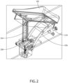
- FIG. 2 a perspective view of a console mounted armrest according to an exemplary embodiment is shown.
- An arm pad deck (and corresponding arm pad) 202 is pivotably connected to a post 204, disposed at a posterior portion of the arm pad deck 202; the post 204 may be raised and lowered.
- a linkage 206 connects an anterior portion of the arm pad deck 202 to a locking mechanism 208 or a portion of a corresponding armrest proximal to the locking mechanism 208.
- the linkage 206 causes the arm pad deck 202 to tilt.
- the shape of the linkage 206 and the points of connection between the linkage 206 and the armrest or locking mechanism 208 define the relationship between the linear displacement of the post 204 and magnitude of tilt.
- a single control element 210 actuates the locking mechanism 208 to set the linear displacement of the post 204, and thereby the tilt of the arm pad deck 202.
- the single control element 210 may comprise an extended rod to allow the user to actuate the locking mechanism 208 while the user's arm is on the arm pad deck 202.
- FIG. 3 a perspective, exploded view of a console mounted armrest according to an exemplary embodiment is shown.
- An arm pad deck 302 is pivotably connected to a post 304 at a posterior portion via a post connection pin 316 and pivotably connected to a linkage 306 at an anterior portion via linkage connection pin 318.
- a locking mechanism 308 controls the linear displacement of the post 304.
- the locking mechanism 308 is actuated by a single control element 310.
- the single control element 310 may comprise a rod that engages one of a plurality of post grooves 320 defined by the post 304.
- Each of the plurality of post grooves 320 defines a fixed position of the post 304 and corresponding tilt of the arm pad deck 302 to maintain a relationship between an arm pad 312 and control such as a side stick control.
- a post spring 314 biases the post 304 upward.
- the post 304 is released to travel up toward a user's arm. The user may then apply a downward force to the arm pad 312 to arrive at the desired position.
- FIGS. 4A-4B side views of a console mounted armrest according to an exemplary embodiment are shown.
- a post 404 connected to an arm pad deck 402 is fully retracted within the armrest and held in place via a locking mechanism 408 having a single control element 410 that engages a post groove 420 defined by the post 404.
- a post spring 414 configured to bias the post 404 upward is in a state of maximum extension.
- a linkage 406 connecting the arm pad deck 402 to the locking mechanism 408 controls the tilt of the arm pad deck 402 to rest flush with the armrest.
- the post 404 In a fully extended orientation (such as in FIG. 4B ), the post 404 is fully extended, with a portion of the post 404 within the locking mechanism 408 and held in position via the single control element 410 engaging a different post groove 420 defined by the post 404.
- the post spring 414 is in a state of minimum extension.
- the linkage 406 connecting the arm pad deck 402 to the locking mechanism 408 controls the tilt of the arm pad deck 402 to maintain a relationship between the arm pad deck 402 and a corresponding control.
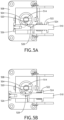
- the locking mechanism 508 defines a shaft to accommodate and guide post 504.
- the post 504 defines a plurality of post grooves 520; the post grooves 520 configured to engage a control element 510.
- the control element 510 defines a control groove 528.
- control element 510 includes stops 524, 526 that define engaged and disengaged states of the locking mechanism 508.
- a control element spring 522 biases the control element 510 toward the engaged state.
- control element 510 When engaged (such as in FIG. 5A ), a portion of the control element 510 is coincident with one of the post grooves 520.
- the post 504 is held in a fixed position defined by the post groove 520, which also control the tilt of an arm pad via a linkage 506.
- the control groove 528 is coincident with the post 504 so that the post 504 can move past the control element 510.
- the post 504 may move (for example, via a post spring 514) until the control element 510 coincides with one of the post grooves 520, at which point the control element spring 522 biases the control element 510 toward the engaged state.
Abstract
Description
- The present disclosure relates to armrests, and more specifically, sidestick control armrests.
- In many aircraft, a pilot's seating position is defined by a desirable line of sight such that the pilot's head is in substantially the same location within the cockpit regardless of the pilot's size. However, aircraft controls, particularly sidestick controls, are in a fixed location such that relation between the pilot's arm and sidestick control may be substantially different depending on the size of the pilot.
- Existing console mounted armrests require multiple points of adjustment to comfortably accommodate differently sized pilots. Multiple points of adjustment create clutter, confusion, and added complexity.
- In one aspect, embodiments of the inventive concepts disclosed herein are directed to a console mounted armrest having an adjustable post to raise and lower the armrest, and a linkage. The linkage defines the tilt of the armrest with respect to the post. A single control mechanism controls the motion of the post, and thereby also controls the tilt of the armrest to maintain a desirable orientation with respect to the sidestick.
- In a further aspect, the control mechanism defines multiple positive lock-out positions with respect to the post such that the control mechanism will always engage one of the positive lock-out positions.
- It is to be understood that both the foregoing general description and the following detailed description are exemplary and explanatory only and should not restrict the scope of the claims. The accompanying drawings, which are incorporated in and constitute a part of the specification, illustrate exemplary embodiments of the inventive concepts disclosed herein and together with the general description, serve to explain the principles.
- The numerous advantages of the embodiments of the inventive concepts disclosed herein may be better understood by those skilled in the art by reference to the accompanying figures in which:
-
FIG. 1 shows an environmental view of a console mounted armrest according to an exemplary embodiment; -
FIG. 2 shows a perspective view of a console mounted armrest according to an exemplary embodiment; -
FIG. 3 shows a perspective, exploded view of a console mounted armrest according to an exemplary embodiment; -
FIG. 4A shows a side view of a console mounted armrest according to an exemplary embodiment; -
FIG. 4B shows a side view of a console mounted armrest according to an exemplary embodiment; -
FIG. 5A shows a top, detail view of a locking mechanism according to an exemplary embodiment; -
FIG. 5B shows a top, detail view of a locking mechanism according to an exemplary embodiment; - Before explaining at least one embodiment of the inventive concepts disclosed herein in detail, it is to be understood that the inventive concepts are not limited in their application to the details of construction and the arrangement of the components or steps or methodologies set forth in the following description or illustrated in the drawings. In the following detailed description of embodiments of the instant inventive concepts, numerous specific details are set forth in order to provide a more thorough understanding of the inventive concepts. However, it will be apparent to one of ordinary skill in the art having the benefit of the instant disclosure that the inventive concepts disclosed herein may be practiced without these specific details. In other instances, well-known features may not be described in detail to avoid unnecessarily complicating the instant disclosure. The inventive concepts disclosed herein are capable of other embodiments or of being practiced or carried out in various ways. Also, it is to be understood that the phraseology and terminology employed herein is for the purpose of description and should not be regarded as limiting.
- As used herein a letter following a reference numeral is intended to reference an embodiment of the feature or element that may be similar, but not necessarily identical, to a previously described element or feature bearing the same reference numeral (e.g., 1, 1a, 1b). Such shorthand notations are used for purposes of convenience only, and should not be construed to limit the inventive concepts disclosed herein in any way unless expressly stated to the contrary.
- Further, unless expressly stated to the contrary, "or" refers to an inclusive or and not to an exclusive or. For example, a condition A or B is satisfied by anyone of the following: A is true (or present) and B is false (or not present), A is false (or not present) and B is true (or present), and both A and B are true (or present).
- In addition, use of the "a" or "an" are employed to describe elements and components of embodiments of the instant inventive concepts. This is done merely for convenience and to give a general sense of the inventive concepts, and "a" and "an" are intended to include one or at least one and the singular also includes the plural unless it is obvious that it is meant otherwise.
- Finally, as used herein any reference to "one embodiment," or "some embodiments" means that a particular element, feature, structure, or characteristic described in connection with the embodiment is included in at least one embodiment of the inventive concepts disclosed herein. The appearances of the phrase "in some embodiments" in various places in the specification are not necessarily all referring to the same embodiment, and embodiments of the inventive concepts disclosed may include one or more of the features expressly described or inherently present herein, or any combination of sub-combination of two or more such features, along with any other features which may not necessarily be expressly described or inherently present in the instant disclosure.
- Broadly, embodiments of the inventive concepts disclosed herein are directed to a console mounted armrest having an adjustable post to raise and lower the armrest, and a linkage. The linkage defines the tilt of the armrest with respect to the post. A single control mechanism controls the motion of the post, and thereby also controls the tilt of the armrest to maintain a desirable orientation with respect to the sidestick. The control mechanism defines multiple positive lock-out positions with respect to the post such that the control mechanism will always engage one of the positive lock-out positions.
- Referring to
FIG. 1 , an environmental view of a console mounted armrest according to an exemplary embodiment is shown. The console mounted armrest includes anarm pad deck 102 connected to alocking mechanism 108 view a verticallydisplaceable post 104. Thepost 104 moves up and down at the discretion of the user to maintain thearm pad deck 102 in a desired orientation with respect to asidestick 100 or other such control element. As thepost 104 moves up and down, alinkage 106 connected to thearm pad deck 102 alters the tilt of thearm pad deck 102 to maintain the orientation. Thelinkage 106 defines the tilt with respect to the linear vertical displacement of thepost 104. - Because the tilt and vertical displacement are related, both may be controlled by the
locking mechanism 108. Asingle control element 110 allows the user to adjust both the height and tilt of the armrest. - Referring to
FIG. 2 , a perspective view of a console mounted armrest according to an exemplary embodiment is shown. An arm pad deck (and corresponding arm pad) 202 is pivotably connected to apost 204, disposed at a posterior portion of thearm pad deck 202; thepost 204 may be raised and lowered. Alinkage 206 connects an anterior portion of thearm pad deck 202 to alocking mechanism 208 or a portion of a corresponding armrest proximal to thelocking mechanism 208. - As the
post 204 is raised and lowered, thelinkage 206 causes thearm pad deck 202 to tilt. The shape of thelinkage 206 and the points of connection between thelinkage 206 and the armrest orlocking mechanism 208 define the relationship between the linear displacement of thepost 204 and magnitude of tilt. - In at least one embodiment, a
single control element 210 actuates thelocking mechanism 208 to set the linear displacement of thepost 204, and thereby the tilt of thearm pad deck 202. Thesingle control element 210 may comprise an extended rod to allow the user to actuate thelocking mechanism 208 while the user's arm is on thearm pad deck 202. - Referring to
FIG. 3 , a perspective, exploded view of a console mounted armrest according to an exemplary embodiment is shown. Anarm pad deck 302 is pivotably connected to apost 304 at a posterior portion via apost connection pin 316 and pivotably connected to alinkage 306 at an anterior portion vialinkage connection pin 318. Alocking mechanism 308 controls the linear displacement of thepost 304. Thelocking mechanism 308 is actuated by asingle control element 310. Thesingle control element 310 may comprise a rod that engages one of a plurality ofpost grooves 320 defined by thepost 304. Each of the plurality ofpost grooves 320 defines a fixed position of thepost 304 and corresponding tilt of thearm pad deck 302 to maintain a relationship between anarm pad 312 and control such as a side stick control. - In at least one embodiment, a
post spring 314 biases thepost 304 upward. In such embodiment, when thesingle control element 310 is actuated, thepost 304 is released to travel up toward a user's arm. The user may then apply a downward force to thearm pad 312 to arrive at the desired position. - Referring to
FIGS. 4A-4B , side views of a console mounted armrest according to an exemplary embodiment are shown. In a fully retracted orientation (such as inFIG. 4A ), apost 404 connected to anarm pad deck 402 is fully retracted within the armrest and held in place via alocking mechanism 408 having asingle control element 410 that engages apost groove 420 defined by thepost 404. In at least one embodiment, apost spring 414 configured to bias thepost 404 upward is in a state of maximum extension. Alinkage 406 connecting thearm pad deck 402 to thelocking mechanism 408 controls the tilt of thearm pad deck 402 to rest flush with the armrest. - In a fully extended orientation (such as in
FIG. 4B ), thepost 404 is fully extended, with a portion of thepost 404 within thelocking mechanism 408 and held in position via thesingle control element 410 engaging adifferent post groove 420 defined by thepost 404. In at least one embodiment, thepost spring 414 is in a state of minimum extension. Thelinkage 406 connecting thearm pad deck 402 to thelocking mechanism 408 controls the tilt of thearm pad deck 402 to maintain a relationship between thearm pad deck 402 and a corresponding control. - Referring to
FIGS. 5A-5B , top, detail views of alocking mechanism 508 according to an exemplary embodiment are shown. Thelocking mechanism 508 defines a shaft to accommodate and guidepost 504. Thepost 504 defines a plurality ofpost grooves 520; thepost grooves 520 configured to engage acontrol element 510. Furthermore, thecontrol element 510 defines acontrol groove 528. - In at least one embodiment, the
control element 510 includesstops locking mechanism 508. In at least one embodiment, acontrol element spring 522 biases thecontrol element 510 toward the engaged state. - When engaged (such as in
FIG. 5A ), a portion of thecontrol element 510 is coincident with one of thepost grooves 520. Thepost 504 is held in a fixed position defined by thepost groove 520, which also control the tilt of an arm pad via a linkage 506. - Likewise, when disengaged (such as in
FIG. 5B ), thecontrol groove 528 is coincident with thepost 504 so that thepost 504 can move past thecontrol element 510. Thepost 504 may move (for example, via a post spring 514) until thecontrol element 510 coincides with one of thepost grooves 520, at which point thecontrol element spring 522 biases thecontrol element 510 toward the engaged state. - It is believed that the inventive concepts disclosed herein and many of their attendant advantages will be understood by the foregoing description of embodiments of the inventive concepts disclosed, and it will be apparent that various changes may be made in the form, construction, and arrangement of the components thereof without departing from the broad scope of the inventive concepts disclosed herein or without sacrificing all of their material advantages; and individual features from various embodiments may be combined to arrive at other embodiments. The form herein before described being merely an explanatory embodiment thereof, it is the intention of the following claims to encompass and include such changes. Furthermore, any of the features disclosed in relation to any of the individual embodiments may be incorporated into any other embodiment.
Claims (14)
- An adjustable armrest comprising:an arm pad deck;a post connected to the arm pad deck;a linkage connected to the arm pad deck; anda locking mechanism,wherein:
the linkage defines a tilt angle of the arm deck as a function of a vertical position of the post. - The adjustable armrest of claim 1, wherein:the post is pivotably connected to the arm pad deck at a posterior portion; andthe linkage is connected to the arm pad deck at an anterior portion.
- The adjustable armrest of claim 1 or 2, wherein the linkage is pivotably connected to the locking mechanism.
- The adjustable armrest of claim 1, 2 or 3, wherein the post defines a plurality of post grooves, each corresponding to a vertical position of the post with respect to the locking mechanism.
- The adjustable armrest of claim 4, wherein the locking mechanism includes a single control element configured to releasably engage one of the plurality of post grooves.
- The adjustable armrest of claim 5, wherein:the single control element defines a control groove; andthe locking mechanism defines an engaged state and a disengaged state, the engaged state corresponding to the single control element disposed such that at least a portion of the single control element engages one of the plurality of post grooves, and the disengaged state corresponding to the single control element disposed such that the control groove is coincident with the post so that the post is allowed to translate vertically.
- The adjustable armrest of any preceding claim, further comprising a post spring configured to bias the post upward.
- A sidestick control armrest comprising the adjustable armrest of any preceding claim.
- A system comprising:an arm pad deck;a post connected to the arm pad deck defining a plurality of post grooves, each corresponding to a vertical position of the post;a linkage connected to the arm pad deck; anda locking mechanism comprising:
a single control element configured to releasably engage one of the post grooves,wherein:
the linkage defines a tilt angle of the arm deck as a function of a vertical position of the post. - The system of claim 9, wherein:the post is pivotably connected to the arm pad deck at a posterior portion; andthe linkage is connected to the arm pad deck at an anterior portion.
- The system of claim 9 or 10, wherein the linkage is pivotably connected to the locking mechanism.
- The system of claim 9, 10 or 11, wherein:the single control element defines a control groove; andthe locking mechanism defines an engaged state and a disengaged state, the engaged state corresponding to the single control element disposed such that at least a portion of the single control element engages one of the plurality of post grooves, and the disengaged state corresponding to the single control element disposed such that the control groove is coincident with the post so that the post is allowed to translate vertically.
- The system of any of claims 9 to 12, wherein the locking mechanism further comprises a control spring configured to bias the single control element into the engaged state.
- The system of any of claims 9 to 13, further comprising a post spring configured to bias the post upward
Applications Claiming Priority (1)
| Application Number | Priority Date | Filing Date | Title |
|---|---|---|---|
| US17/462,278 US11857085B2 (en) | 2021-08-31 | 2021-08-31 | Single control console mounted armrest |
Publications (1)
| Publication Number | Publication Date |
|---|---|
| EP4140889A1 true EP4140889A1 (en) | 2023-03-01 |
Family
ID=83151542
Family Applications (1)
| Application Number | Title | Priority Date | Filing Date |
|---|---|---|---|
| EP22192951.6A Pending EP4140889A1 (en) | 2021-08-31 | 2022-08-30 | Single control console mounted armrest |
Country Status (2)
| Country | Link |
|---|---|
| US (1) | US11857085B2 (en) |
| EP (1) | EP4140889A1 (en) |
Families Citing this family (2)
| Publication number | Priority date | Publication date | Assignee | Title |
|---|---|---|---|---|
| USD993146S1 (en) * | 2021-05-11 | 2023-07-25 | Textron Innovations, Inc. | Cockpit center console armrest |
| US11890978B1 (en) * | 2023-06-29 | 2024-02-06 | Protomet Corporation | Pop up arm rest |
Citations (6)
| Publication number | Priority date | Publication date | Assignee | Title |
|---|---|---|---|---|
| GB2068719A (en) * | 1980-01-31 | 1981-08-19 | Nordfor Skogsdon Ab | An arm rest |
| US4763860A (en) * | 1985-01-18 | 1988-08-16 | Societe Nationale Industrielle Et Aerospatiale | Cockpit provided with a lateral control stick adapted to be actuated one-handed and seat for such a cockpit |
| FR2770468A1 (en) * | 1997-11-05 | 1999-05-07 | Noremat | Seat for driver of working machinery |
| US20070096531A1 (en) * | 2005-10-27 | 2007-05-03 | Crown Equipment Corporation | Adjustable armrest mechanism for a materials handling vehicle |
| DE102006053329A1 (en) * | 2005-11-15 | 2007-05-16 | Skoda Auto As | Armrest for motor vehicle, has arm support body with height adjustment against retainer housing that includes perpendicular, upwards opened, parallel cylinders, where pistons are guided in cylinders and downwards projects from body |
| US20190351799A1 (en) * | 2018-05-16 | 2019-11-21 | Korea Aerospace Industries, Ltd. | Armrest for fighter |
Family Cites Families (14)
| Publication number | Priority date | Publication date | Assignee | Title |
|---|---|---|---|---|
| US4307913A (en) | 1980-06-02 | 1981-12-29 | Milsco Manufacturing Company | Adjustable arm-rest for vehicle seat |
| US4887866A (en) * | 1987-11-12 | 1989-12-19 | Dexta Corporation | Adjustable armrest |
| EP1486142A1 (en) | 1992-06-15 | 2004-12-15 | Herman Miller, Inc. | Seating structure for a chair |
| US5636899A (en) * | 1995-12-07 | 1997-06-10 | Atlantic Automotive Components, Inc. | Kinematic structure for vehicle armrest |
| US8146999B2 (en) * | 2009-09-02 | 2012-04-03 | AMI Industries. Inc | Aircraft seat with adjustable armrest |
| US9144316B1 (en) | 2012-11-08 | 2015-09-29 | Igal Sapir | Programmer's chair |
| DE102012112558B4 (en) | 2012-12-18 | 2015-04-30 | Grammer Ag | Armrest assembly for a seat, in particular for a vehicle seat, and vehicle seat |
| US9844268B2 (en) * | 2015-03-16 | 2017-12-19 | Aaron DeJule | Sitting apparatus |
| DE102015012632A1 (en) * | 2015-09-30 | 2017-03-30 | Grammer Ag | Armrest for one seat and seat with armrest |
| US10829202B2 (en) * | 2017-09-05 | 2020-11-10 | Textron Innovations Inc. | Adjustable armrest system |
| US10879489B2 (en) * | 2018-05-21 | 2020-12-29 | Korea Advanced Institute Of Science And Technology | Organic device having protective film and method of manufacturing the same |
| US10941540B2 (en) | 2019-01-30 | 2021-03-09 | Caterpillar Inc. | Adjustable operator console for machine control |
| US11459109B2 (en) * | 2020-02-27 | 2022-10-04 | Ami Industries, Inc. | Automatic aircraft pilot seat side-stick armrest |
| US11618572B2 (en) * | 2020-05-01 | 2023-04-04 | B/E Aerospace, Inc. | Adjustable armrest assembly |
-
2021
- 2021-08-31 US US17/462,278 patent/US11857085B2/en active Active
-
2022
- 2022-08-30 EP EP22192951.6A patent/EP4140889A1/en active Pending
Patent Citations (6)
| Publication number | Priority date | Publication date | Assignee | Title |
|---|---|---|---|---|
| GB2068719A (en) * | 1980-01-31 | 1981-08-19 | Nordfor Skogsdon Ab | An arm rest |
| US4763860A (en) * | 1985-01-18 | 1988-08-16 | Societe Nationale Industrielle Et Aerospatiale | Cockpit provided with a lateral control stick adapted to be actuated one-handed and seat for such a cockpit |
| FR2770468A1 (en) * | 1997-11-05 | 1999-05-07 | Noremat | Seat for driver of working machinery |
| US20070096531A1 (en) * | 2005-10-27 | 2007-05-03 | Crown Equipment Corporation | Adjustable armrest mechanism for a materials handling vehicle |
| DE102006053329A1 (en) * | 2005-11-15 | 2007-05-16 | Skoda Auto As | Armrest for motor vehicle, has arm support body with height adjustment against retainer housing that includes perpendicular, upwards opened, parallel cylinders, where pistons are guided in cylinders and downwards projects from body |
| US20190351799A1 (en) * | 2018-05-16 | 2019-11-21 | Korea Aerospace Industries, Ltd. | Armrest for fighter |
Also Published As
| Publication number | Publication date |
|---|---|
| US11857085B2 (en) | 2024-01-02 |
| US20230061160A1 (en) | 2023-03-02 |
Similar Documents
| Publication | Publication Date | Title |
|---|---|---|
| EP4140889A1 (en) | Single control console mounted armrest | |
| CN105480420B (en) | Multi-position seat for a driver | |
| RU2499731C2 (en) | Perfected aircraft cockpit | |
| US9033284B2 (en) | Integrated seat mounted inceptor | |
| US4466662A (en) | Powered articulated headrest system | |
| US4700921A (en) | Adjustable pedestal for boat seats | |
| US4160534A (en) | Operating station for aircraft refueling boom | |
| US4004763A (en) | Articulated high "G" pilot S seat | |
| US11912414B2 (en) | Cockpit center console armrest | |
| US5028016A (en) | Modular work station design for aircraft | |
| US20060186715A1 (en) | Seating unit with components controllable by a control device | |
| EP3023329B1 (en) | Displacement system of a seat, in particular an airplane seat | |
| US10571952B2 (en) | Multi-mode gimbal transmitter | |
| EP3702282A1 (en) | Multi-position adjustable headrest assembly | |
| US7182402B1 (en) | Seat recline control override | |
| US11459109B2 (en) | Automatic aircraft pilot seat side-stick armrest | |
| JPS61169396A (en) | Cockpit | |
| WO1998049056A1 (en) | A collective detent system for vertical takeoff flight operations | |
| US4264044A (en) | Operating station for aircraft refueling boom | |
| EP0451438B1 (en) | Ejection seats for military aircraft | |
| US11873089B2 (en) | Powered paragliding harness | |
| US20220119117A1 (en) | Interior layout of an aircraft cabin and associated method | |
| US11697366B2 (en) | Adjustment mechanism and headrest | |
| US11281236B2 (en) | Alternative yaw control | |
| US2707087A (en) | Method and means for increasing airplane pilot's resistance to acceleration forces |
Legal Events
| Date | Code | Title | Description |
|---|---|---|---|
| PUAI | Public reference made under article 153(3) epc to a published international application that has entered the european phase |
Free format text: ORIGINAL CODE: 0009012 |
|
| STAA | Information on the status of an ep patent application or granted ep patent |
Free format text: STATUS: THE APPLICATION HAS BEEN PUBLISHED |
|
| AK | Designated contracting states |
Kind code of ref document: A1 Designated state(s): AL AT BE BG CH CY CZ DE DK EE ES FI FR GB GR HR HU IE IS IT LI LT LU LV MC MK MT NL NO PL PT RO RS SE SI SK SM TR |
|
| STAA | Information on the status of an ep patent application or granted ep patent |
Free format text: STATUS: REQUEST FOR EXAMINATION WAS MADE |
|
| 17P | Request for examination filed |
Effective date: 20230825 |
|
| RBV | Designated contracting states (corrected) |
Designated state(s): AL AT BE BG CH CY CZ DE DK EE ES FI FR GB GR HR HU IE IS IT LI LT LU LV MC MK MT NL NO PL PT RO RS SE SI SK SM TR |
|
| P01 | Opt-out of the competence of the unified patent court (upc) registered |
Effective date: 20230922 |