EP4140887B1 - Zusammenklappbare begleitstufe - Google Patents
Zusammenklappbare begleitstufe Download PDFInfo
- Publication number
- EP4140887B1 EP4140887B1 EP22189200.3A EP22189200A EP4140887B1 EP 4140887 B1 EP4140887 B1 EP 4140887B1 EP 22189200 A EP22189200 A EP 22189200A EP 4140887 B1 EP4140887 B1 EP 4140887B1
- Authority
- EP
- European Patent Office
- Prior art keywords
- armrest
- assembly
- support leg
- bottom side
- attendant
- Prior art date
- Legal status (The legal status is an assumption and is not a legal conclusion. Google has not performed a legal analysis and makes no representation as to the accuracy of the status listed.)
- Active
Links
Images


Classifications
-
- B—PERFORMING OPERATIONS; TRANSPORTING
- B64—AIRCRAFT; AVIATION; COSMONAUTICS
- B64D—EQUIPMENT FOR FITTING IN OR TO AIRCRAFT; FLIGHT SUITS; PARACHUTES; ARRANGEMENT OR MOUNTING OF POWER PLANTS OR PROPULSION TRANSMISSIONS IN AIRCRAFT
- B64D11/00—Passenger or crew accommodation; Flight-deck installations not otherwise provided for
- B64D11/06—Arrangements of seats, or adaptations or details specially adapted for aircraft seats
- B64D11/0639—Arrangements of seats, or adaptations or details specially adapted for aircraft seats with features for adjustment or converting of seats
- B64D11/0644—Adjustable arm rests
-
- B—PERFORMING OPERATIONS; TRANSPORTING
- B60—VEHICLES IN GENERAL
- B60N—SEATS SPECIALLY ADAPTED FOR VEHICLES; VEHICLE PASSENGER ACCOMMODATION NOT OTHERWISE PROVIDED FOR
- B60N2/00—Seats specially adapted for vehicles; Arrangement or mounting of seats in vehicles
- B60N2/75—Arm-rests
- B60N2/79—Adaptations for additional use of the arm-rests
-
- B—PERFORMING OPERATIONS; TRANSPORTING
- B64—AIRCRAFT; AVIATION; COSMONAUTICS
- B64D—EQUIPMENT FOR FITTING IN OR TO AIRCRAFT; FLIGHT SUITS; PARACHUTES; ARRANGEMENT OR MOUNTING OF POWER PLANTS OR PROPULSION TRANSMISSIONS IN AIRCRAFT
- B64D11/00—Passenger or crew accommodation; Flight-deck installations not otherwise provided for
- B64D11/06—Arrangements of seats, or adaptations or details specially adapted for aircraft seats
- B64D11/0646—Seats characterised by special features of stationary arms, foot or head rests
-
- B—PERFORMING OPERATIONS; TRANSPORTING
- B64—AIRCRAFT; AVIATION; COSMONAUTICS
- B64D—EQUIPMENT FOR FITTING IN OR TO AIRCRAFT; FLIGHT SUITS; PARACHUTES; ARRANGEMENT OR MOUNTING OF POWER PLANTS OR PROPULSION TRANSMISSIONS IN AIRCRAFT
- B64D11/00—Passenger or crew accommodation; Flight-deck installations not otherwise provided for
- B64D11/06—Arrangements of seats, or adaptations or details specially adapted for aircraft seats
- B64D11/0648—Lower frame constructions
-
- B—PERFORMING OPERATIONS; TRANSPORTING
- B64—AIRCRAFT; AVIATION; COSMONAUTICS
- B64D—EQUIPMENT FOR FITTING IN OR TO AIRCRAFT; FLIGHT SUITS; PARACHUTES; ARRANGEMENT OR MOUNTING OF POWER PLANTS OR PROPULSION TRANSMISSIONS IN AIRCRAFT
- B64D11/00—Passenger or crew accommodation; Flight-deck installations not otherwise provided for
- B64D11/06—Arrangements of seats, or adaptations or details specially adapted for aircraft seats
- B64D11/0691—Arrangements of seats, or adaptations or details specially adapted for aircraft seats specially adapted for cabin crew
Definitions
- the field of the invention relates to passenger seats for passenger vehicles, and, more particularly, to armrest assemblies for passenger seats including but not limited to aircraft passenger seats.
- Passenger vehicles such as aircraft, buses, trains, ships, and automobiles, include passenger seats for passengers to sit in and utilize during travel. Sometimes, it may be preferable or necessary to reach some area above the passenger seat.
- aircraft, buses, trains, and other vehicles sometimes include overhead stowage compartments that a passenger may use to stow his or her luggage during travel. Most passenger seats do not include any mechanism to facilitate reaching such areas.
- a passenger seat might include a step, such steps are fixed, thereby reducing the functionality of other components and taking up valuable space within the passenger vehicle.
- Document EP3782909 describes a step assembly installable in a structure such as a housing of an armrest assembly.
- the step assembly includes a base attachable to the structure including a mounting plate having a low profile and a fixed receptacle to be received in the structure.
- a step plate is pivotally attached along a first end to the base along a lower end of the receptacle.
- the step plate is pivotable between a stowed position in which the step plate is housed within the fixed receptacle and a deployed position in which the step plate is outside of the fixed receptacle.
- Document US2020/172225 describes an aisle seat having a receiver for attaching a seat slide and step to a seat element in various use positions.
- the seat slide and step may stow under the seat in a first position corresponding to a stowed position, attach alongside the seat to a seat element in a second position corresponding to a step position for the flight crew to access overhead items, and may attach alongside the side to a seat element in a third position corresponding to a seat slide position for helping transfer a limited mobility passenger into the passenger seat.
- an armrest assembly for a passenger seat includes an armrest and an attendant step.
- the armrest may include a top side and a bottom side.
- the attendant step may be connected to the bottom side of the armrest.
- the attendant step may include a step that is movable between a stowed position and a deployed position relative to the bottom side of the armrest
- the attendant step assembly may include a first support leg and a second support leg.
- the first support leg and the second support leg may each be connected to the step and pivotably connected to the bottom side of the armrest.
- the step may be movable between the stowed position and the deployed position.
- first support leg and the second support leg may each be pivotable and slidable relative to the step.
- the first support leg in the stowed position, may extend at a 10° angle relative to the bottom side of the armrest, and, in the deployed position, the first support leg may extend at a 60° angle relative to the bottom side of the armrest.
- the step may be vertically below the bottom side of the armrest.
- the step in the stowed position, may be a first distance below the bottom side of the armrest, and, in the deployed position, the step may be a second distance below the bottom side of the armrest that is greater than the first distance.
- the armrest assembly may be vertically movable between a lowered position and a raised position, and, in the lowered position, the step may be in the stowed position.
- the attendant step assembly may include at least one support connecting the step to the bottom side of the armrest.
- the at least one support may include a first end and a second end opposite from the first end. The first end may be pivotably connected to the bottom side of the armrest.
- the second end is at least one of pivotable relative to the step or slidable relative to the step.
- the step may define at least one guide channel.
- the second end of the at least one support may be at least partially received within the at least one guide channel and may be linearly movable along the at least one guide channel.
- the at least one guide channel may be elongated and may include a first end and a second end opposite from the first end.
- the first end may include a first stabilizing pocket
- the second end may include a second stabilizing pocket.
- the second end of the at least one support in the stowed position, may engage the second stabilizing pocket of the at least one guide channel, and, in the deployed position, the second end of the at least one support may engage the first stabilizing pocket of the at least one guide channel.
- the first end of the support may include a stopper slot.
- the armrest assembly may include a stopper pin retained within the stopper slot, and the stopper pin may be fixed relative to the at least one support.
- the stopper pin may engage a first end of the stopper slot when the step is in the stowed position and may engage a second end of the stopper slot when the step is in the deployed position.
- the step may be biased towards the deployed position.
- step assemblies for passenger seats. While the step assemblies are discussed for use with aircraft seats, they are by no means so limited. Rather, embodiments of the step assemblies may be used in passenger seats or other seats of any type or otherwise as desired.
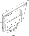
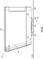
- FIG. 1 is a perspective view of an armrest assembly 100 according to certain embodiments of the present invention.
- the armrest assembly 100 may be an armrest assembly for a handicap passenger seat area on an aircraft, although it need not be in other embodiments.
- the particular armrest 102 illustrated should not be considered limiting on the disclosure.
- the attendant step assembly 104 is illustrated on the armrest assembly 100, in other embodiments, the attendant step assembly 104 may be provided on other structures and/or other locations associated with a passenger seat as desired.
- the attendant step assembly 104 may be provided with various structures that are movable between a stowed position and a deployed position.
- the armrest 102 includes a top side 106 and a bottom side 108.
- the armrest 102 may include a pocket 202 that is provided between the top side 106 and the bottom side 108.
- the pocket 202 may be used by the passenger.
- the armrest 102 may be formed of materials including but not limited to aluminum, stainless steel, aramid fibers, polycarbonate, polypropylene, other metallic materials, composite materials, or other similar materials.
- the armrest 102 may include various other combinations or sub-combinations of components that may provide support for a passenger and/or may otherwise be used by the passenger.
- the armrest 102 is movable between a raised (or deployed) position ( FIG. 9A ) and a lowered (or stowed) position relative to a floor 902, which may be a cabin floor of an aircraft or other support surface as desired.
- a distance between the floor 902 and the bottom side 108 of the armrest 102 in the raised position ( FIG. 9A ) is greater than a distance between the floor 902 and the bottom side 108 of the armrest 102 in the stowed position ( FIG. 9B ).
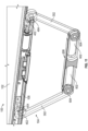
- the attendant step assembly 104 is connected to the bottom side 108 of the armrest 102 and includes support legs 302 and a step 304. As illustrated, the support legs 302 support and connect the step 304 relative to the bottom side 108 of the armrest 102. In certain embodiments, and as illustrated in FIGS. 9A-B , the attendant step assembly 104 is connected to the bottom side 108 of the armrest 102 such that the step 304 is below the bottom side 108 of the armrest 102 in both the raised position and the lowered position. Stated differently, the step 304 may be outside of the armrest 102 in both the raised position and the lowered position.
- the attendant step assembly 104 is adjustable between a stowed position ( FIG. 9B ) and a deployed position ( FIG. 9A ).
- the attendant step assembly 104 is in the stowed position when the armrest is in the lowered position and the attendant step assembly 104 is in the deployed position when the armrest 102 is in the raised position.
- the armrest assembly 104 may optionally be biased towards the deployed position.
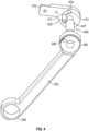
- the attendant step assembly 104 is illustrated in detail.
- the components of the attendant step assembly 104 may be formed of materials including, but not limited to, aluminum, stainless steel, aramid fibers, polycarbonate, polypropylene, other metallic materials, composite materials, other similar materials, combinations thereof, or other materials as desired.
- the support legs 302 and step 304 are constructed from metal.
- each support leg 302 of the attendant step assembly 104 includes a first end 306 and a second end 308 opposite the first end 306.
- the first end 306 is connected to the bottom side 108 of the armrest 102, and the second end 308 is connected to the step 304.
- the first end 306 of each support leg 302 may be connected to the bottom side 108 of the armrest 102 using one or more brackets 310. While two brackets 310 are illustrated, any number of brackets 310 and/or other support structures may be utilized as desired to connect the support legs 302 to the armrest 102. In certain embodiments, and as best illustrated in FIGS.
- movement mechanisms 405 are provided such that the first end 306 is pivotably connected to the brackets 310 and thus is pivotable relative to the armrest 102.
- the movement mechanism 405 includes a pin 407 and a biasing member 409, including but not limited to a torsion spring.
- the biasing member 409 may bias the attendant step assembly 104 towards the deployed position.
- the first end 306 of each support leg 302 may be supported on the pin 407 such that the support leg 302 is rotatable about the pin.
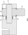
- a stopper pin 402 and a stopper slot 404 may be provided to limit rotation of the support leg 302 relative to the brackets 310 and thus relative to the armrest 102.
- the stopper pin 402 is received within an aperture 406 in the first end 306 of the support leg 302 such that the stopper pin 402 is fixed relative to the support leg 302, and the stopper slot 404 is provided in one or more of the brackets 310.
- the stopper pin 402 may be monolithically or integrally formed with the support leg 302.
- the stopper pin 402 may be provided on the bracket(s) 310 and/or fixed relative to the bracket(s) 310, and the stopper slot 404 is provided on the support leg 302.
- the stopper pin 402 is at least partially received in the stopper slot 404 and is movable within the stopper slot 404 (or vice versa) such that the stopper pin 402 can selectively engage a first end 411 or a second end 413 of the stopper slot 404 depending on rotation of the support leg 302. In certain embodiments, the stopper pin 402 engages the first end 411 of the stopper slot 404 when the attendant step assembly 104 is in the deployed position and engages the second end 413 of the stopper slot 404 when the attendant step assembly 104 is in the stowed position.
- the orientation and configuration of the first end 411 and the second end 413 may define a maximum angle and a minimum angle of the support leg 302 relative to the bottom side 108 of the armrest 102.
- the support leg 302 in the stowed position e.g., where the stopper pin 402 engages the second end 413 of the stopper slot 404
- the support leg 302 may extend at an angle of 10° relative to the bottom side 108
- the deployed position e.g., where the stopper pin 402 engages the first end 411 of the stopper slot 404
- the support leg 302 may extend at an angle of 60° relative to the bottom side 108.
- the support leg 302 may be adjusted to extend at other angles as desired in either the deployed position or the stowed position, and the support leg 302 may further be adjusted such that a length of the stopper slot 404 (and thus the range of motion of the support leg 302) is adjusted to any range of angles as desired relative to the bottom side 108. While a stopper pin and stopper slot are illustrated as movement limiters, in other embodiments, or devices or components may be utilized to control movement of the support legs 302 relative to the armrest 102.
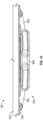
- each support leg 302 is connected to the step 304.
- the second end 308 of each support leg 302 is pivotably connected to the step 304 such that an angle of the support legs 302 relative to the step 304 is adjustable.
- the first end 306 of each support leg 302 pivotably connected to the armrest 102 and the second end 308 of each support leg 302 pivotably connected to the step 304 may allow for the attendant step assembly 104 to be movable between the stowed position and the deployed position.
- the second end 308 may be pivotably connected to the step 304 using various suitable devices or mechanisms as desired.
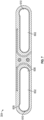
- each support leg 302 in addition to being pivotably connected to the step 304, the second end 308 of each support leg 302 may also be linearly movable relative to the step 304.
- the support legs 302 and/or the step 304 may include various devices or mechanisms such that the second ends 308 are linearly movable and pivotable relative to the step 304.
- the support legs 302 include rollers 604, and the step 304 includes guide channels 602 that receive the respective rollers 604. The number of guide channels 602 illustrated should not be considered limiting on the disclosure.
- the step 304 may include openings 603 that may facilitate linear movement of the support legs 302 relative to the step 304.
- each guide channel 602 includes a first end 607 and a second end 609.
- the guide channels 602 may extend substantially horizontally, although in other embodiments the guide channels 602 may extend in various directions as desired and/or may have various shapes or sizes as desired.
- the roller 604 (and/or second end 308) of a particular support leg 302 may engage the first end 607 when the attendant step assembly 104 is in the deployed position and may engage the second end 609 when the attendant step assembly 104 is in the stowed position.
- one or both of the ends 607, 609 may include a stabilizing pocket 608.
- first ends 607 are illustrated as having stabilizing pockets 608 while the second ends 609 do not; however, in other embodiments, the second ends 609 may include stabilizing pockets 608.
- the stabilizing pockets 608 may facilitate temporary positioning of the support legs 302 in the stowed position or the deployed position. In other words, some minimal force may optionally be required to move the rollers 604 from the stabilizing pockets 608.
- the step 304 may optionally include a gripping feature 606 on a top side of the step 304 and may provide grip for a user engaging the step 304.
- the gripping feature 606 is anti-slip tape, although other suitable gripping features may be utilized as desired.
- the attendant step assembly 104 is movable between a stowed position and a deployed position.
- the attendant step assembly 104 is biased towards the deployed position.
- attendant step assembly 104 may be in the deployed position while the armrest is in the raised position as illustrated in FIG. 9A .
- the attendant step assembly 104 may automatically move from the stowed position to the deployed position (e.g., because it is biased towards the deployed position).
- the attendant step assembly 104 is in the stowed position when the armrest 102 is in the lowered position.
- moving the armrest 102 from the raised position to the lowered position may automatically move the attendant step assembly 104 from the deployed position to the stowed position.
- the attendant step assembly 104 may be utilized by a person as a step, for example to reach an overhead compartment or other location as desired.
- the user may step on the step 304, and the gripping feature 606 may improve the engagement between the user's foot and the step 304.
- the attendant step assembly 104 may have a minimized or reduced profile, even though the attendant step assembly 104 is not housed within the armrest 102.
- the rotational and linear movement of the support legs 302 relative to the step 304 may allow for the attendant step assembly 104 to have the reduced profile in the stowed position.
- the reduced profile of the stowed attendant step assembly 104 may have a height of less than or equal to 7.62 cm (3 inches), such as less than or equal to 5.08 cm (2 inches), such as less than or equal to 2.54 cm (1 inch). In other embodiments, the stowed attendant step assembly 104 may have other heights as desired.
- the attendant step assembly 104 may have reduced manufacturing costs, reduced manufacturing waste, and/or improved optimization for loads that a fixed step assembly may experience.
Landscapes
- Engineering & Computer Science (AREA)
- Aviation & Aerospace Engineering (AREA)
- Transportation (AREA)
- Mechanical Engineering (AREA)
- Seats For Vehicles (AREA)
Claims (13)
- Armlehnenanordnung (100) für einen Passagiersitz, wobei die Armlehnenanordnung (100) umfasst:eine Armlehne (102), die eine Oberseite (106) und eine Unterseite (108) umfasst; undeine Dienststufenanordnung (104), die mit der Unterseite (108) der Armlehne (102) verbunden ist,
wobei die Dienststufenanordnung (104) eine Stufe (304) umfasst, die relativ zur Unterseite (108) der Armlehne (102) zwischen einer verstauten Position und einer ausgefahrenen Position bewegbar ist,dadurch gekennzeichnet, dass die Dienststufenanordnung (104) weiterhin ein erstes Stützbein (302) und ein zweites Stützbein (302) umfasst, wobei das erste Stützbein (302) und das zweite Stützbein (302) jeweils mit der Stufe (304) verbunden und schwenkbar mit der Unterseite (108) der Armlehne (102) verbunden sind, so dass die Stufe (304) zwischen der verstauten Position und der ausgefahrenen Position bewegbar ist, undwobei der erste Stützbein (302) und der zweite Stützbein (302) jeweils relativ zur Stufe (304) schwenkbar und verschiebbar sind. - Armlehnenanordnung nach Anspruch 1, dadurch gekennzeichnet, dass der erste Stützbein (302) in der Verstaustellung in einem Winkel von 10° zur Unterseite (108) der Armlehne (102) verläuft, und wobei sich das erste Stützbein (302) in der ausgefahrenen Position in einem Winkel von 60° relativ zur Unterseite (108) der Armlehne (102) erstreckt.
- Armlehnenanordnung nach Anspruch 1 oder 2, dadurch gekennzeichnet, dass sich die Stufe (304) in der verstauten Position und in der ausgefahrenen Position vertikal unterhalb der Unterseite (108) der Armlehne (102) befindet.
- Armlehnenanordnung nach einem der Ansprüche 1 bis 3, dadurch gekennzeichnet, dass sich die Stufe (304) in der verstauten Position in einem ersten Abstand unterhalb der Unterseite (108) der Armlehne (102) befindet, und wobei sich die Stufe (304) in der ausgefahrenen Position in einem als der erste Abstand größeren zweiten Abstand unterhalb der Unterseite (108) der Armlehne (102) befindet.
- Armlehnenanordnung nach einem der Ansprüche 1 bis 4, dadurch gekennzeichnet, dass die Armlehnenanordnung (100) vertikal zwischen einer abgesenkten Position und einer angehobenen Position bewegbar ist, und wobei in der abgesenkten Position sich die Stufe (304) im verstauten Position befindet.
- Armlehnenanordnung nach einem der Ansprüche 1 bis 5, dadurch gekennzeichnet, dass die Dienststufenanordnung (104) außerdem mindestens eine Stütze umfasst, die die Stufe (304) mit der Unterseite (108) der Armlehne (102) verbindet, wobei die mindestens eine Stütze ein erstes Ende und ein dem ersten Ende gegenüberliegendes zweites Ende umfasst, und wobei das erste Ende schwenkbar mit der Unterseite (108) der Armlehne (102) verbunden ist.
- Armlehnenanordnung nach Anspruch 6, dadurch gekennzeichnet, dass das zweite Ende mindestens ein Ende unter einem schwenkbaren Ende relativ zur Stufe (304) oder einem verschiebbaren Ende relativ zur Stufe (304) ist.
- Armlehnenanordnung nach Anspruch 6 oder 7, dadurch gekennzeichnet, dass die Stufe (304) mindestens einen Führungskanal definiert, und wobei das zweite Ende der mindestens einen Stütze mindestens teilweise in dem mindestens einen Führungskanal aufgenommen und linear entlang des mindestens einen Führungskanals beweglich ist.
- Armlehnenanordnung nach Anspruch 8, dadurch gekennzeichnet, dass der mindestens eine Führungskanal (602) länglich ist und ein erstes Ende (607) und ein dem ersten Ende gegenüberliegendes zweites Ende (609) umfasst, wobei das erste Ende eine erste Stabilisierungstasche (608) und das zweite Ende eine zweite Stabilisierungstasche (608) umfasst.
- Armlehnenanordnung nach Anspruch 9, dadurch gekennzeichnet, dass in der verstauten Position das zweite Ende (609) des mindestens einen Stützbeines (302) in die zweite Stabilisierungstasche (608) des mindestens einen Führungskanals (602) und in der ausgefahrenen Position das zweite Ende des mindestens einen Stützbeines in die erste Stabilisierungstasche (608) der mindestens einen Führungskanal eingreift.
- Armlehnenanordnung nach einem der Ansprüche 6 bis 10, dadurch gekennzeichnet, dass das erste Ende des Stützbeines (302) einen Anschlagschlitz (404) aufweist, wobei die Armlehnenanordnung (100) weiterhin einen im Anschlagschlitz gehaltenen Anschlagstift (402) umfasst, wobei der Anschlagstift relativ zum mindestens einen Stützbein (302) fixiert ist.
- Armlehnenanordnung nach Anspruch 11, wobei der Anschlagstift (402) in ein erstes Ende des Anschlagschlitzes (404), wenn sich die Stufe (304) in der verstauten Position befindet, und in ein zweites Ende des Anschlagschlitzes, wenn sich die Stufe (304) in der ausgefahrenen Position befindet, eingreift.
- Armlehnenanordnung nach einem der Ansprüche 1 bis 12, dadurch gekennzeichnet, dass die Stufe (304) in Richtung der ausgefahrenen Position vorspannt ist.
Applications Claiming Priority (1)
| Application Number | Priority Date | Filing Date | Title |
|---|---|---|---|
| US17/462,782 US11760245B2 (en) | 2021-08-31 | 2021-08-31 | Foldable attendant step |
Publications (2)
| Publication Number | Publication Date |
|---|---|
| EP4140887A1 EP4140887A1 (de) | 2023-03-01 |
| EP4140887B1 true EP4140887B1 (de) | 2024-10-30 |
Family
ID=82850377
Family Applications (1)
| Application Number | Title | Priority Date | Filing Date |
|---|---|---|---|
| EP22189200.3A Active EP4140887B1 (de) | 2021-08-31 | 2022-08-08 | Zusammenklappbare begleitstufe |
Country Status (2)
| Country | Link |
|---|---|
| US (1) | US11760245B2 (de) |
| EP (1) | EP4140887B1 (de) |
Families Citing this family (1)
| Publication number | Priority date | Publication date | Assignee | Title |
|---|---|---|---|---|
| US11760245B2 (en) | 2021-08-31 | 2023-09-19 | Safran Seats Usa Llc | Foldable attendant step |
Family Cites Families (11)
| Publication number | Priority date | Publication date | Assignee | Title |
|---|---|---|---|---|
| US2093455A (en) * | 1935-04-27 | 1937-09-21 | American Car & Foundry Co | Folding footrest |
| DE3634839A1 (de) * | 1986-10-13 | 1988-04-21 | Messerschmitt Boelkow Blohm | Fahrzeugsitz |
| DE202012003042U1 (de) | 2012-03-26 | 2013-06-27 | Zim Flugsitz Gmbh | Flugzeugsitz |
| US20140110193A1 (en) * | 2012-10-24 | 2014-04-24 | Deere & Company | Folding step assembly |
| US8905354B2 (en) * | 2013-01-31 | 2014-12-09 | Bell Helicopter Textron Inc. | External maintenance step and hand hold |
| DE202013012277U1 (de) | 2013-04-05 | 2015-12-18 | Recaro Aircraft Seating Gmbh & Co. Kg | Sitzvorrichtung |
| EP2796371B1 (de) | 2013-04-23 | 2019-11-20 | Airbus Operations GmbH | Flugbegleitersitz mit zusätzlicher Abstützung |
| DE102015122830A1 (de) | 2015-12-23 | 2017-06-29 | Recaro Aircraft Seating Gmbh & Co. Kg | Flugzeugsitzvorrichtung |
| US20200172225A1 (en) | 2018-12-03 | 2020-06-04 | B/E Aerospace, Inc. | Aisle track system for aircraft and accessible lavatory configuration |
| US11407514B2 (en) * | 2019-08-20 | 2022-08-09 | B/E Aerospace, Inc. | End bay assembly with deployable step and deployable step constructions |
| US11760245B2 (en) | 2021-08-31 | 2023-09-19 | Safran Seats Usa Llc | Foldable attendant step |
-
2021
- 2021-08-31 US US17/462,782 patent/US11760245B2/en active Active
-
2022
- 2022-08-08 EP EP22189200.3A patent/EP4140887B1/de active Active
Also Published As
| Publication number | Publication date |
|---|---|
| EP4140887A1 (de) | 2023-03-01 |
| US20230066591A1 (en) | 2023-03-02 |
| US11760245B2 (en) | 2023-09-19 |
Similar Documents
| Publication | Publication Date | Title |
|---|---|---|
| EP3741677B1 (de) | Positionsverstellbare armlehnenanordnungen für passagiersitze | |
| CN109484653B (zh) | 用于飞行器座椅的滑动底座组件 | |
| EP2828159B1 (de) | Freitragender tisch in tablettform und flugzeugpassagiersuite damit | |
| EP2724938B1 (de) | Flugzeugmonument mit einem integrierten Flugbegleitersitz und Flugzeugkabinenzone | |
| EP3129288B1 (de) | Gleit- und schwenktabletttisch | |
| US8439448B2 (en) | Buckle for center occupant for bench seat with extended travel | |
| US11407514B2 (en) | End bay assembly with deployable step and deployable step constructions | |
| EP3248875B1 (de) | Stewardsitz, system mit einem stewardsitz sowie anordnung und flugzeugbereich mit dem system | |
| EP4335747A1 (de) | Flugzeugschottmontierter pilotsitz mit horizontaler und vertikaler einstellung | |
| EP4140887B1 (de) | Zusammenklappbare begleitstufe | |
| US7240949B1 (en) | Adjustable seat assembly | |
| CA3062212A1 (en) | Passenger seat reconfigurable for seating or storage | |
| US11219324B2 (en) | Cupholder assembly and table including the same | |
| CN107298041B (zh) | 车辆座椅调整系统 | |
| US12202605B2 (en) | Retractable divider for passenger seat | |
| EP4263351B1 (de) | Flugzeugsitzkonstruktion mit montierbarer lebensmittelschale | |
| US8851568B2 (en) | Retractable passenger seat | |
| US12187436B2 (en) | Center console with privacy divider for passenger seat | |
| US12122521B2 (en) | Offset helicopter pilot seat with centered vertical motion system | |
| US20220119117A1 (en) | Interior layout of an aircraft cabin and associated method | |
| EP4353595B1 (de) | Konsolenmontierter tabletttisch mit spiralförmigem drehpunkt | |
| EP4015386B1 (de) | Flugbegleitersitz mit höhenverstellbarer sitzschale | |
| US11548643B2 (en) | Cabin attendant seat with height adjustable seat pan | |
| EP4122829A1 (de) | Beinauflage mit fussstütze für flugbegleiter | |
| EP4353534A1 (de) | Systeme, verfahren und vorrichtungen für ablagen am sitz |
Legal Events
| Date | Code | Title | Description |
|---|---|---|---|
| PUAI | Public reference made under article 153(3) epc to a published international application that has entered the european phase |
Free format text: ORIGINAL CODE: 0009012 |
|
| STAA | Information on the status of an ep patent application or granted ep patent |
Free format text: STATUS: THE APPLICATION HAS BEEN PUBLISHED |
|
| AK | Designated contracting states |
Kind code of ref document: A1 Designated state(s): AL AT BE BG CH CY CZ DE DK EE ES FI FR GB GR HR HU IE IS IT LI LT LU LV MC MK MT NL NO PL PT RO RS SE SI SK SM TR |
|
| STAA | Information on the status of an ep patent application or granted ep patent |
Free format text: STATUS: REQUEST FOR EXAMINATION WAS MADE |
|
| 17P | Request for examination filed |
Effective date: 20230608 |
|
| RBV | Designated contracting states (corrected) |
Designated state(s): AL AT BE BG CH CY CZ DE DK EE ES FI FR GB GR HR HU IE IS IT LI LT LU LV MC MK MT NL NO PL PT RO RS SE SI SK SM TR |
|
| GRAP | Despatch of communication of intention to grant a patent |
Free format text: ORIGINAL CODE: EPIDOSNIGR1 |
|
| STAA | Information on the status of an ep patent application or granted ep patent |
Free format text: STATUS: GRANT OF PATENT IS INTENDED |
|
| INTG | Intention to grant announced |
Effective date: 20240607 |
|
| GRAS | Grant fee paid |
Free format text: ORIGINAL CODE: EPIDOSNIGR3 |
|
| GRAA | (expected) grant |
Free format text: ORIGINAL CODE: 0009210 |
|
| STAA | Information on the status of an ep patent application or granted ep patent |
Free format text: STATUS: THE PATENT HAS BEEN GRANTED |
|
| AK | Designated contracting states |
Kind code of ref document: B1 Designated state(s): AL AT BE BG CH CY CZ DE DK EE ES FI FR GB GR HR HU IE IS IT LI LT LU LV MC MK MT NL NO PL PT RO RS SE SI SK SM TR |
|
| REG | Reference to a national code |
Ref country code: GB Ref legal event code: FG4D |
|
| REG | Reference to a national code |
Ref country code: CH Ref legal event code: EP |
|
| REG | Reference to a national code |
Ref country code: IE Ref legal event code: FG4D |
|
| REG | Reference to a national code |
Ref country code: DE Ref legal event code: R096 Ref document number: 602022007191 Country of ref document: DE |
|
| REG | Reference to a national code |
Ref country code: LT Ref legal event code: MG9D |
|
| REG | Reference to a national code |
Ref country code: NL Ref legal event code: MP Effective date: 20241030 |
|
| PG25 | Lapsed in a contracting state [announced via postgrant information from national office to epo] |
Ref country code: HR Free format text: LAPSE BECAUSE OF FAILURE TO SUBMIT A TRANSLATION OF THE DESCRIPTION OR TO PAY THE FEE WITHIN THE PRESCRIBED TIME-LIMIT Effective date: 20241030 Ref country code: PT Free format text: LAPSE BECAUSE OF FAILURE TO SUBMIT A TRANSLATION OF THE DESCRIPTION OR TO PAY THE FEE WITHIN THE PRESCRIBED TIME-LIMIT Effective date: 20250228 Ref country code: IS Free format text: LAPSE BECAUSE OF FAILURE TO SUBMIT A TRANSLATION OF THE DESCRIPTION OR TO PAY THE FEE WITHIN THE PRESCRIBED TIME-LIMIT Effective date: 20250228 |
|
| PG25 | Lapsed in a contracting state [announced via postgrant information from national office to epo] |
Ref country code: FI Free format text: LAPSE BECAUSE OF FAILURE TO SUBMIT A TRANSLATION OF THE DESCRIPTION OR TO PAY THE FEE WITHIN THE PRESCRIBED TIME-LIMIT Effective date: 20241030 Ref country code: NL Free format text: LAPSE BECAUSE OF FAILURE TO SUBMIT A TRANSLATION OF THE DESCRIPTION OR TO PAY THE FEE WITHIN THE PRESCRIBED TIME-LIMIT Effective date: 20241030 |
|
| REG | Reference to a national code |
Ref country code: AT Ref legal event code: MK05 Ref document number: 1736672 Country of ref document: AT Kind code of ref document: T Effective date: 20241030 |
|
| PG25 | Lapsed in a contracting state [announced via postgrant information from national office to epo] |
Ref country code: BG Free format text: LAPSE BECAUSE OF FAILURE TO SUBMIT A TRANSLATION OF THE DESCRIPTION OR TO PAY THE FEE WITHIN THE PRESCRIBED TIME-LIMIT Effective date: 20241030 |
|
| PG25 | Lapsed in a contracting state [announced via postgrant information from national office to epo] |
Ref country code: ES Free format text: LAPSE BECAUSE OF FAILURE TO SUBMIT A TRANSLATION OF THE DESCRIPTION OR TO PAY THE FEE WITHIN THE PRESCRIBED TIME-LIMIT Effective date: 20241030 |
|
| PG25 | Lapsed in a contracting state [announced via postgrant information from national office to epo] |
Ref country code: NO Free format text: LAPSE BECAUSE OF FAILURE TO SUBMIT A TRANSLATION OF THE DESCRIPTION OR TO PAY THE FEE WITHIN THE PRESCRIBED TIME-LIMIT Effective date: 20250130 |
|
| PG25 | Lapsed in a contracting state [announced via postgrant information from national office to epo] |
Ref country code: GR Free format text: LAPSE BECAUSE OF FAILURE TO SUBMIT A TRANSLATION OF THE DESCRIPTION OR TO PAY THE FEE WITHIN THE PRESCRIBED TIME-LIMIT Effective date: 20250131 Ref country code: AT Free format text: LAPSE BECAUSE OF FAILURE TO SUBMIT A TRANSLATION OF THE DESCRIPTION OR TO PAY THE FEE WITHIN THE PRESCRIBED TIME-LIMIT Effective date: 20241030 Ref country code: LV Free format text: LAPSE BECAUSE OF FAILURE TO SUBMIT A TRANSLATION OF THE DESCRIPTION OR TO PAY THE FEE WITHIN THE PRESCRIBED TIME-LIMIT Effective date: 20241030 |
|
| PG25 | Lapsed in a contracting state [announced via postgrant information from national office to epo] |
Ref country code: PL Free format text: LAPSE BECAUSE OF FAILURE TO SUBMIT A TRANSLATION OF THE DESCRIPTION OR TO PAY THE FEE WITHIN THE PRESCRIBED TIME-LIMIT Effective date: 20241030 |
|
| PG25 | Lapsed in a contracting state [announced via postgrant information from national office to epo] |
Ref country code: RS Free format text: LAPSE BECAUSE OF FAILURE TO SUBMIT A TRANSLATION OF THE DESCRIPTION OR TO PAY THE FEE WITHIN THE PRESCRIBED TIME-LIMIT Effective date: 20250130 |
|
| PG25 | Lapsed in a contracting state [announced via postgrant information from national office to epo] |
Ref country code: SM Free format text: LAPSE BECAUSE OF FAILURE TO SUBMIT A TRANSLATION OF THE DESCRIPTION OR TO PAY THE FEE WITHIN THE PRESCRIBED TIME-LIMIT Effective date: 20241030 |
|
| PG25 | Lapsed in a contracting state [announced via postgrant information from national office to epo] |
Ref country code: DK Free format text: LAPSE BECAUSE OF FAILURE TO SUBMIT A TRANSLATION OF THE DESCRIPTION OR TO PAY THE FEE WITHIN THE PRESCRIBED TIME-LIMIT Effective date: 20241030 |
|
| PG25 | Lapsed in a contracting state [announced via postgrant information from national office to epo] |
Ref country code: EE Free format text: LAPSE BECAUSE OF FAILURE TO SUBMIT A TRANSLATION OF THE DESCRIPTION OR TO PAY THE FEE WITHIN THE PRESCRIBED TIME-LIMIT Effective date: 20241030 |
|
| PG25 | Lapsed in a contracting state [announced via postgrant information from national office to epo] |
Ref country code: RO Free format text: LAPSE BECAUSE OF FAILURE TO SUBMIT A TRANSLATION OF THE DESCRIPTION OR TO PAY THE FEE WITHIN THE PRESCRIBED TIME-LIMIT Effective date: 20241030 |
|
| PG25 | Lapsed in a contracting state [announced via postgrant information from national office to epo] |
Ref country code: SK Free format text: LAPSE BECAUSE OF FAILURE TO SUBMIT A TRANSLATION OF THE DESCRIPTION OR TO PAY THE FEE WITHIN THE PRESCRIBED TIME-LIMIT Effective date: 20241030 |
|
| PG25 | Lapsed in a contracting state [announced via postgrant information from national office to epo] |
Ref country code: CZ Free format text: LAPSE BECAUSE OF FAILURE TO SUBMIT A TRANSLATION OF THE DESCRIPTION OR TO PAY THE FEE WITHIN THE PRESCRIBED TIME-LIMIT Effective date: 20241030 |
|
| PG25 | Lapsed in a contracting state [announced via postgrant information from national office to epo] |
Ref country code: IT Free format text: LAPSE BECAUSE OF FAILURE TO SUBMIT A TRANSLATION OF THE DESCRIPTION OR TO PAY THE FEE WITHIN THE PRESCRIBED TIME-LIMIT Effective date: 20241030 |
|
| REG | Reference to a national code |
Ref country code: DE Ref legal event code: R097 Ref document number: 602022007191 Country of ref document: DE |
|
| PLBE | No opposition filed within time limit |
Free format text: ORIGINAL CODE: 0009261 |
|
| STAA | Information on the status of an ep patent application or granted ep patent |
Free format text: STATUS: NO OPPOSITION FILED WITHIN TIME LIMIT |
|
| PG25 | Lapsed in a contracting state [announced via postgrant information from national office to epo] |
Ref country code: SE Free format text: LAPSE BECAUSE OF FAILURE TO SUBMIT A TRANSLATION OF THE DESCRIPTION OR TO PAY THE FEE WITHIN THE PRESCRIBED TIME-LIMIT Effective date: 20241030 |
|
| 26N | No opposition filed |
Effective date: 20250731 |
|
| PGFP | Annual fee paid to national office [announced via postgrant information from national office to epo] |
Ref country code: DE Payment date: 20250819 Year of fee payment: 4 |
|
| PGFP | Annual fee paid to national office [announced via postgrant information from national office to epo] |
Ref country code: FR Payment date: 20250821 Year of fee payment: 4 |
|
| REG | Reference to a national code |
Ref country code: CH Ref legal event code: H13 Free format text: ST27 STATUS EVENT CODE: U-0-0-H10-H13 (AS PROVIDED BY THE NATIONAL OFFICE) Effective date: 20260324 |