EP4140876A2 - Steuerfläche und verfahren zum herstellen davon - Google Patents
Steuerfläche und verfahren zum herstellen davon Download PDFInfo
- Publication number
- EP4140876A2 EP4140876A2 EP22179474.6A EP22179474A EP4140876A2 EP 4140876 A2 EP4140876 A2 EP 4140876A2 EP 22179474 A EP22179474 A EP 22179474A EP 4140876 A2 EP4140876 A2 EP 4140876A2
- Authority
- EP
- European Patent Office
- Prior art keywords
- control surface
- truss core
- spar
- cover
- fabricating
- Prior art date
- Legal status (The legal status is an assumption and is not a legal conclusion. Google has not performed a legal analysis and makes no representation as to the accuracy of the status listed.)
- Granted
Links
Images






Classifications
-
- B—PERFORMING OPERATIONS; TRANSPORTING
- B64—AIRCRAFT; AVIATION; COSMONAUTICS
- B64C—AEROPLANES; HELICOPTERS
- B64C9/00—Adjustable control surfaces or members, e.g. rudders
-
- B—PERFORMING OPERATIONS; TRANSPORTING
- B29—WORKING OF PLASTICS; WORKING OF SUBSTANCES IN A PLASTIC STATE IN GENERAL
- B29D—PRODUCING PARTICULAR ARTICLES FROM PLASTICS OR FROM SUBSTANCES IN A PLASTIC STATE
- B29D99/00—Subject matter not provided for in other groups of this subclass
- B29D99/0025—Producing blades or the like, e.g. blades for turbines, propellers, or wings
- B29D99/0028—Producing blades or the like, e.g. blades for turbines, propellers, or wings hollow blades
-
- B—PERFORMING OPERATIONS; TRANSPORTING
- B64—AIRCRAFT; AVIATION; COSMONAUTICS
- B64C—AEROPLANES; HELICOPTERS
- B64C3/00—Wings
- B64C3/18—Spars; Ribs; Stringers
- B64C3/185—Spars
-
- B—PERFORMING OPERATIONS; TRANSPORTING
- B64—AIRCRAFT; AVIATION; COSMONAUTICS
- B64C—AEROPLANES; HELICOPTERS
- B64C3/00—Wings
- B64C3/26—Construction, shape, or attachment of separate skins, e.g. panels
-
- B—PERFORMING OPERATIONS; TRANSPORTING
- B64—AIRCRAFT; AVIATION; COSMONAUTICS
- B64C—AEROPLANES; HELICOPTERS
- B64C9/00—Adjustable control surfaces or members, e.g. rudders
- B64C2009/005—Ailerons
-
- Y—GENERAL TAGGING OF NEW TECHNOLOGICAL DEVELOPMENTS; GENERAL TAGGING OF CROSS-SECTIONAL TECHNOLOGIES SPANNING OVER SEVERAL SECTIONS OF THE IPC; TECHNICAL SUBJECTS COVERED BY FORMER USPC CROSS-REFERENCE ART COLLECTIONS [XRACs] AND DIGESTS
- Y02—TECHNOLOGIES OR APPLICATIONS FOR MITIGATION OR ADAPTATION AGAINST CLIMATE CHANGE
- Y02T—CLIMATE CHANGE MITIGATION TECHNOLOGIES RELATED TO TRANSPORTATION
- Y02T50/00—Aeronautics or air transport
- Y02T50/40—Weight reduction
Definitions
- the present disclosure generally relates to composite aircraft structures, and deals more particularly with a control surface formed of co-consolidated thermoplastic components, as well as a method of making the control surface using induction consolidation.
- Control surfaces for aircraft are sometimes produced using composite materials in which a honeycomb core is sandwiched between two outer facesheets, all formed from thermoset materials.
- the honeycomb core and the facesheets are co-cured at relatively low pressures and temperatures in an autoclave, resulting in a continuous attachment of the facesheets to the honeycomb core across the entire area of the control surface. This continuous attachment makes the control surface more subject to propagation of disbonds between the facesheets and the core.
- Control surfaces made from thermosets are also time consuming to produce because of the time needed for curing. While control surfaces of the type described above are satisfactory for many applications, they may not be suitable for newer applications where wings are thinner yet require greater fracture toughness and residual strength, particularly when operating at higher in-service temperatures.
- control surface that is relatively easy to fabricate and which possesses higher structural performance characteristics, particularly at higher in-service temperatures. There is also a need for a method of making such control surfaces at higher production rates.
- the disclosure relates in general to composite structures used in aircraft, and more specifically to a light weight control surface exhibiting high residual strength, improved fracture toughness properties, and damage tolerance.
- a control surface for a wing of an airplane comprises a forward section and aft section.
- the forward section includes a cover formed of thermoplastic.
- a control surface for a wing of an airplane.
- the control surface comprises a truss core, and a skin covering the truss core.
- the control surface further comprises a cover configured to cover an end of the trust core.
- a method is provided of making a control surface for an aircraft.
- the method comprises fabricating first and second sections of the control surface and assembling them together.
- Fabricating the first section includes fabricating a cover, fabricating a spar and attaching the spar to the cover.
- Fabricating the second section comprises fabricating a truss core and applying a skin over the truss core.
- a method is provided of making a control surface for an aircraft, comprising fabricating a cover, a spar, a truss core, and applying a skin over the truss core.
- the cover and the spar are welded together.
- control surface is relative thin and lightweight yet exhibits higher residual strength and improved fracture toughness properties as well as damage tolerance.
- a further advantage is that the control surface can be operated at higher in-service temperatures.
- Another advantage is that control surface can be more easily fabricated at higher production rates.
- a control surface for a wing of an airplane comprises a forward section, the forward section including a cover formed of a thermoplastic; and an aft section joined to the forward section and formed of a thermoplastic.
- control surface is one wherein the aft section includes a truss core.
- control surface is one wherein the forward section includes a spar formed of a thermoplastic, and the cover and the spar are co-consolidated.
- control surface is one wherein the aft section includes a truss core, and the truss core includes a cutout therein forming contact areas between the truss core and the spar.
- control surface is one wherein the truss core includes webs extending in a chordwise direction of the control surface, and the control surface further comprises a plate located at a forward end of the truss core and configured to support the webs at the forward end of the truss core.
- control surface is one wherein the plate is adhesively attached to the forward end of the truss core.
- control surface is one wherein the plate is welded to the forward end of the truss core.
- control surface is one wherein the plate includes slots configured to receive the forward end of the truss core therein.
- control surface is one wherein the truss core is formed of a thermoplastic and includes a top chord, a bottom chord and a plurality of webs connecting the top chord with the bottom chord.
- control surface is one wherein the webs extend in a spanwise direction of the control surface.
- control surface is one wherein the webs extend in a chordwise direction of the control surface.
- control surface is one wherein the forward section includes a skin formed of thermoplastic and covering the top chord and the bottom chord.
- a control surface for a wing of an airplane comprises a truss core; a skin covering the truss core; and a cover configured to cover an end of the truss core.
- control surface further comprises a spar located between and attached to the cover and the truss core.
- control surface is one wherein each of the truss core, the cover and the spar are formed of a thermoplastic.
- control surface is one wherein the truss core includes a top chord, a bottom chord and a plurality of webs connecting the top chord with the bottom chord.
- control surface is one wherein the truss core includes a cutout therein forming contact areas between the truss core and the spar.
- control surface further comprises a plate located between the spar and the truss core, the plate including slots therein configured to receive and support an end of the truss core therein.
- control surface is one wherein the skin includes a joint therein and, the spar includes a cap spanning the joint.
- control surface is one wherein the spar and the cover are co-consolidated.
- control surface is one wherein the cover, the truss core and the spar is a consolidated structure.
- a method of making a control surface for an aircraft comprises fabricating a first section of the control surface, including fabricating a cover, fabricating a spar, and attaching the spar to the cover; fabricating a second section of the control surface, including fabricating a truss core, and applying a skin over the truss core; and assembling the first and second sections together.
- the method is one wherein fabricating the cover includes laying up plies of fiber reinforced thermoplastic fabric over a layup mandrel, fabricating the spar includes laying up plies of a fiber reinforced thermoplastic tape, and attaching the spar to the cover.
- the method is one wherein attaching the spar to the cover is performed using induction consolidation.
- the method is one wherein fabricating the truss core includes laying up webs, a top chord and a bottom chord, and co-consolidating the webs and the top chord and the bottom chord, and applying the skin includes laying up plies of a fiber reinforced thermoplastic fabric over the top chord and the bottom chord.
- the method further comprises forming a cutout in the truss core defining contact areas configured to contact and be joined to the spar.
- the method is one wherein assembling the first and second sections together is performed using induction consolidation.
- the method further comprises fabricating a plate having slots therein configured to receive portions of the truss core, inserting the portions of the truss core into the slots, and adhesively bonding the portions of the truss core with the plate.
- the method is one wherein assembling the first and second sections together is performed by induction consolidation using smart susceptors.
- the method is one wherein assembling the first and second sections together is performed by induction welding.
- method of making a control surface for an aircraft comprising fabricating a cover, a spar, a truss core, and applying a skin over the truss core; and welding the cover and the spar together.
- the method further comprises joining the cover and spar with the truss core and the skin by induction consolidation.
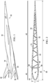
- an aircraft 30 includes a fuselage 32 and wings 34, some of which include control surfaces 36 used to control the roll, pitch, yaw or other dynamics of the aircraft 30.
- the aircraft 30 is designed to achieve supersonic (in excess of Mach 1) speeds.
- control surface includes but is not limited to ailerons, elevators, rudders, elevons, ailerons, flapperons, and similar structures such as small wings.
- Figures 2 and 3 illustrate a control surface 36 of the aircraft 30 in the form of elevon 38 located along the trailing edge 39 of a wing 34.
- the control surface 36 has a length L ( Figure 3 ) extending in the spanwise direction 54 of the wing 34, and a width W extending in the chordwise direction 56.
- the control surface 36 will typically have a thickness T that is relatively thin in order to reduce aerodynamic drag, particularly at supersonic speeds.
- the width W of the control surface 36 will depend on the particular application.
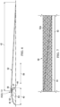
- the control surface 36 broadly comprises a forward section 40 and an aft section 42 connected together at joints 58.
- Each of the forward and aft sections 40, 42 is formed of fiber reinforced thermoplastic components, such as for example and with limitation carbon fiber reinforced PEEK (polyether ether ketone) or PEKK (polyetherketoneketone) although it is possible to form certain of these components formed of other materials, depending on the application.
- the thermoplastic components of the control surface 36 are co-consolidated to form a highly integrated, thin, lightweight control surface structure having superior residual strength, fracture toughness and damage tolerance that is suitable for operation in high temperature environments.
- the forward section 40 of the control surface 36 comprises a cover 44 joined to a spar 48 having a generally C-shaped cross-section.
- the cover 44 forms a leading edge having a rounded shape that enhances the bending resistance of the forward section 40.
- the cover 44 is formed of a carbon fiber reinforced thermoplastic fabric
- the spar 48 is formed of a carbon fiber reinforced thermoplastic tape, however in other examples the use of other forms of fiber reinforced thermoplastics is possible.
- the aft section 42 of the control surface 36 is tapered in the chordwise direction 56, and includes an outer skin 52 that is stiffened by an internal truss core 50.
- the outer skin 52 is formed of multiple facesheets and extends over the entire control surface 36, forming a smooth transition between the forward section 40 and the aft section 42.
- the truss core 50 provides the control surface 36 with improved bending stiffness and torsional resistance.
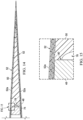
- the design of the truss core 50 can vary with the application, but in the illustrated example, comprises top and bottom chords 68, 70, respectively joined together by angularly oriented webs 72. In the illustrated example, the webs 72 extend in the spanwise direction 54 of the control surface 36.
- the webs 72 extend in the chordwise direction 56.
- the truss core 50 is either tapered or has a constant thickness in the spanwise direction 54 in those examples where the webs 72 extend in the spanwise direction 54.
- the truss core 50 is either tapered or has a constant thickness in the chordwise direction 56.
- the webs 72 comprises thermoplastic composite doublers that are arraigned substantially perpendicular to the chords 68, 70. Still other configurations of the webs 60 are possible.
- the truss core 50 extends through the full thickness of the aft section 42, however in other examples, it extends only partially through the thickness of the aft section 42.
- chords 68, 70, and the webs 72 are formed of multi-ply carbon fiber reinforced thermoplastic tape, while the skin 52 comprises outer facesheets formed of multi-ply carbon fiber reinforced thermoplastic tape or fabric.
- the chords 68, 70, webs 72 and the skin 52 are laid up and co-consolidated using for example, induction heating employing smart susceptors (described later) which allow precise temperature control and short consolidation times.
- the control surface 36 has an axis of symmetry 63 ( Figure 6 ).
- the cover 44 is formed over a layup mandrel 64 by either manual, semi-automated or fully automated application techniques in which multiple plies of fiber reinforced thermoplastic fabric are placed over the mandrel 64.
- the spar 48 comprises a web 60 and a pair of caps 62 that are configured to be connected to the cover 44 along joints 57, as by consolidation through induction heating or other techniques. Any of several configurations of the joints 57 are possible, but in the illustrated example, as best seen in Figures 5A and 6 , the joints 57 are in the form of a lap joint 57 in which the cover 44 overlaps the caps 62 of the spar 48.
- the forward section 40 is connected to the aft section 42 at joints 58 which are in any of several forms.
- the joints 58 comprise a scarf joint 58 in which tapered forwardly extending tabs 52a of the skin 52 on the aft section 42 overlap tapered rear ends of the skin 52 on the cover 44.
- the scarf joint 58 is formed by overlapping the tapered rear ends of the skin 52 on the cover 44 over the tabs 52a of the skin 52 on the aft section 42.
- the joint 58 each comprise a simple butt joint in the skin 52 between the forward section 40 and the aft section 42.
- the caps 62 are located beneath and span the joints 58, thereby strengthening them.
- Other types of joints are possible, such as, without limitation, step lap joints, simple lap joints, and double butt lap joints to name only a few.
- the forward section 40 and the aft section 42 are joined together at the joints 58 either by co-consolidation or by induction welding.
- the layup mandrel 64 is replaced by a consolidation tool 66.
- the joints 57 between the spar 48 and the cover 44 are then consolidated using induction heating or other techniques which heat the joints 58 to the consolidation temperature of the particular thermoplastic being used, thereby co-consolidating the ends of the cover 44 with the caps 62 of the spar.
- Figures 11-13 illustrate additional details of the aft section 42 of the control surface 36, including the truss core 50.
- the elements of the truss core 50 including the top and bottom chords 68, 70, along with the webs 72 are laid up using automatic tape laying (ATL) machines or automatic fiber placement (AFP) machines, depending upon whether fiber reinforced tape or tows are used.
- ATL automatic tape laying
- AFP automatic fiber placement
- mandrels are inserted longitudinally in the openings between the webs 72, following which the truss core layup is placed in solid tooling and heated to consolidation temperature.
- Consolidation pressure applied through the heated tooling results in co-consolidation of the top chord 68, bottom chord 70 and webs 72 into a strong, thin, lightweight consolidated structure.
- the consolidated truss core 50 is then placed in appropriate tooling, which can include a layup mandrel 74 as shown in Figure 11 . Any desired number of fiber reinforced facesheets are then laid up over both the top and bottom chords 68, 70, thereby forming outer skins 52, including the previously mentioned tabs 52a.
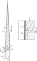
- the forward end of the truss core 50 is slightly uneven after consolidation, making it difficult to achieve full face-to-face contact between the truss core 50 and the spar 48 over a sufficient area. Consequently, it is necessary or desirable to form a cutout 78 in the forward end of the truss core 50 that has a fish mouth shape and defines two contact areas 80 on the truss core 50 that are configured to engage and be the joined to the spar 48.
- the two spaced apart contact areas 80 are respectively located at the top and bottom of the spar 48. However, in other examples, more than two contact areas is possible, and these defined contact areas are located elsewhere at the interface between the truss core 50 and the spar 48.
- Figure 16 shows the aft section 42 of the control surface 36 positioned against the forward section 40 in preparation for connecting these two sections together along joints 58 between them.
- the spar 48 engages the entire contact area 80 of the truss core 50 in full face-to-face contact.
- the free forward end 50a of the truss core 50 is stabilized and supported.
- this support and stabilization is achieved using a slotted plate 86 formed of a fiber reinforced thermoplastic, or a light weight metal such as titanium.
- the slotted plate 86 is a laser sintered part produced by additive manufacturing.
- the slotted plate 86 extends spanwise 54 substantially the entire length L ( Figure 3 ) of the control surface 36 and includes slots 88 therein which form a slot configuration matching the cross-sectional shape of the forward end 50a of the truss core 50.
- the forward end 50a of the truss core 50 is closely received within the slots 88, resulting in the forward end 50a being stabilized and supported in the slotted plate 86.
- an adhesive 90 is used to join the forward end 50a of the truss core 50 to the slotted plate 86.
- the slotted plate 86 is joined to the spar 48 by an adhesive 90.
- the forward end of the truss core 50 is joined to the slotted plate 86 by induction welding.
- the slotted plate 86 is joined to the spar 48 by induction welding.
- the forward and aft sections 40, 42 are connected together though localized welding at the joints 58 using an arrangement such as that shown diagrammatically in Figure 23 .
- the assembled forward and aft sections 40, 42 are placed in tooling that is partially represented in Figure 22 as restraints 92.
- the tooling includes a ferrite sheet 94 surrounded by an induction coil 96 coupled with a suitable source of AC electric power (not shown).
- Smart susceptors 118 are installed between inflatable bladders 100 and the joints 58 being welded.
- the inflatable bladders 100 are inflated to apply consolidation pressure to the joints 58 which is reacted by the restraints 92.
- the smart susceptors 98 are formed of ferromagnetic materials such as alloys of iron (Fe), nickel (Ni) or cobalt (Co), or ferrimagnetic materials such as, without limitation, ferrites.
- the material from which the smart susceptors 98 are formed is chosen to have a Curie temperature close to but slightly higher than the consolidation temperature of the thermoplastic forming the joints 58. The heat produced by the smart susceptors 98 decreases as the temperature increases to the Curie temperature, thereby preventing overheating of the joints 58 while ensuring adequate melting to allow full consolidation.
- Figure 24 illustrates an induction consolidation assembly 120 that can be used to consolidate the components of the control surface 36 into a substantially unitary structure.
- the induction consolidation assembly 120 comprise upper and lower dies 104, 106 respectively, pneumatically operated mandrels 121, a die insert 116 and an inflatable bladder 114.
- the upper and lower dies 104, 106 are formed of a nonconductive material such as ceramic, and the inflatable bladder 114 as well as the die insert 116 are formed of aluminum.
- the die insert 116 has a shape that complements that of the bottom of the control surface layup 122.
- the upper and lower dies 104, 106 have inner die surfaces that are lined with smart susceptors 118 formed of materials similar to the smart susceptors 98 described above in connection with Figure 22 .
- Each of the upper and lower dies 104, 106 includes suitable reinforcement rods 110, and are each provided with an internal electrical induction coil 108 that is coupled with a suitable source of AC power.
- Each of the upper and lower dies 104, 106 includes a means of cooling which, in the illustrated example, comprise fluid passageways 112 that are internal to the induction coil 108.
- the control surface layup 122 is placed in the die insert 116.
- automated equipment such as pneumatic actuators is used to insert the mandrels 121 spanwise within the internal spaces 123 in the control surface layup 122 either before or after the control surface layup 122 is placed in the die insert 116.
- the mandrels 121 are manually inserted.
- the dies 104, 106 are closed, thereby sandwiching the control surface layup 122 between the die insert 116 and the inflatable bladder 114.
- the induction coil 108 is then energized to produce a magnetic field that induces the flow of eddy currents in the smart susceptor 118.
- These eddy currents result in the generation of heat which melts the thermoplastic components of the control surface layup 122.
- the inflatable bladder 114 is inflated to apply consolidation pressure to the control surface layup 122 until the consolidation temperature of the thermoplastic is reached.
- the Curie temperature of the materials from which the smart susceptor 118 are formed are selected to substantially equal or slightly exceed the desired consolidation temperature. Consequently, the consolidation temperature of the thermoplastic is not substantially exceeded because the smart susceptors 118 do not heat beyond their Curie temperature.
- control surface layup 122 Following heating of the control surface layup 122 to its consolidation temperature, the upper and lower dies 104, 106 are cooled, allowing the control surface layup 122 to cool and consolidate, following which the inflatable bladder 114 is deflated and the dies 104, 106 are separated to allow removal of the fully consolidated control surface layup 122.
- Figure 25 broadly illustrates the steps of a method of making a control surface 36 of the type described above in which the truss core 50 extends in the chordwise direction 56.
- the numeral 124 designates the steps followed to fabricate the forward section 40 of the control surface 36
- 126 designates the steps followed to fabricate the aft section 42.
- steps 124 and 126 are carried out independently of and in parallel with each other.
- Fabricating the forward section 40 begins at 128, in which the spar 48 is laid up as a preform, following which, at 130, the spar 48 is placed on a layup mandrel 64. In other examples, the spar 48 is laid up on the layup mandrel 64.
- the cover 44 is laid up over the layup mandrel 64, forming joints 58 between the spar 48 and the cover 44. In other examples, the cover 44 is laid up over the mandrel 64 before the spar 48 is placed on the mandrel 64.
- the layup mandrel 64 is replaced with a consolidation tool 66 and at 136, the cover 44 and spar 48 are consolidated and joined together by induction consolidation in a separate tool. In other examples, the cover 44 and spar 48 are each laid up as a preform and then assembled together on the consolidation tool 66 before being consolidated through induction heating.
- Fabrication of the aft section 42 begins at 138 in which the truss core 50 is laid up.
- a layup mandrel 74 is placed against the forward end of the truss core 50, following which at 142 any number of facesheet plies are laid up over the truss core 50 to form an outer skin 52 which includes forwardly extending tabs 52a.
- the truss core 50 and facesheet plies are co-consolidated.
- the forward end 50a of the truss core 50 is modified either by cutting away a portion thereof to form contact areas 80, or by fabricating and installing a slotted plate 86 to stabilize and support the forward end of the truss core 50.
- the forward and aft sections 40, 42 are assembled together and placed in tooling fixtures. Finally, at 150, the forward and aft sections 40, 42 are joined together by localized induction welding.
- Figure 26 broadly illustrates the steps of a method of making a control surface 36 of the type described above in which the truss core 50 extends in the spanwise direction 54.
- Numeral 152 designates the steps followed to fabricate the forward section 40 of the control surface 36, while 154 designates the steps followed in fabricating the aft section 42.
- steps 152 the process of producing the forward section 40 begins at 156 with laying up the spar 48.
- the spar 48 is placed on a layup mandrel 64, following which at 160 the cover 44 is laid up on the layup mandrel 64 in a manner that forms a joint 58 between the cover 44 and the spar 48.
- the mandrel 64 is replaced with a consolidation tool 66, and at 164 the cover 44 and spar 48 are joined together and co-consolidated by induction consolidation in separate tools.
- the steps for producing the aft section 42 shown at 154 begin at 166 with laying up the truss core 50.
- the facesheets are laid up over the truss core 50 and the mandrel 64, thereby forming a skin 52.
- the facesheets and truss core 50 are co-consolidated.
- the forward and aft sections 40, 42 are assembled together by installing each of them in tooling fixtures.
- the forward and aft sections 40, 42 are joined together through co-consolidation, using induction consolidation.
- consolidation of the truss core 50 as well as co-consolidation of the components in step 174 are carried out using solid tooling.
- Examples of the disclosure find use in a variety of potential applications, particularly in the transportation industry, including for example, aerospace, marine, automotive applications and other application where strong, then lightweight structures such as control surfaces in aircraft are used.
- examples of the disclosure can be used in the context of an aircraft manufacturing and service method 176 as shown in Figure 27 and an aircraft 178 as shown in Figure 28 .
- Aircraft applications of the disclosed examples include a variety of control surfaces such as rudders, elevators, ailerons, elevons and flapperons.
- exemplary method 176 includes specification and design 180 of the aircraft 178 and material procurement 182.
- component and subassembly manufacturing 184 and system integration 186 of the aircraft 178 takes place.
- the aircraft 178 goes through certification and delivery 188 in order to be placed in service 190.
- the aircraft 178 is scheduled for routine maintenance and service 192, which includes modification, reconfiguration, refurbishment, and so on.
- Each of the processes of method 176 is performed or carried out by any of a system integrator, a third party, and/or an operator (e.g., a customer).
- a system integrator includes without limitation any number of aircraft manufacturers and major-system subcontractors;
- a third party can include without limitation any number of vendors, subcontractors, and suppliers;
- an operator includes an airline, leasing company, military entity, service organization, and so on.
- the aircraft 178 produced by exemplary method 176 includes an airframe 194 with a plurality of systems 196, an interior 198 and wings 200.
- the wings 200 includes any number of control surfaces 202.
- Examples of high-level systems 196 include one or more of a propulsion system 204, an electrical system 206, a hydraulic system 208 and an environmental system 210. Any number of other systems is possible.
- an aerospace example is shown, the principles of the disclosure apply to other industries, such as the marine and automotive industries.
- the phrase "at least one of', when used with a list of items, means different combinations of one or more of the listed items can be used and only one of each item in the list can be needed.
- "at least one of item A, item B, and item C" can include, without limitation, item A, item A and item B, or item B. This example also can include item A, item B, and item C or item B and item C.
- the item can be a particular object, thing, or a category. In other words, at least one of means any combination items and number of items can be used from the list but not all of the items in the list are required.
Landscapes
- Engineering & Computer Science (AREA)
- Aviation & Aerospace Engineering (AREA)
- Mechanical Engineering (AREA)
- Laminated Bodies (AREA)
- Moulding By Coating Moulds (AREA)
- Lining Or Joining Of Plastics Or The Like (AREA)
Applications Claiming Priority (1)
| Application Number | Priority Date | Filing Date | Title |
|---|---|---|---|
| US17/446,550 US12157572B2 (en) | 2021-08-31 | 2021-08-31 | Method of making a control surface |
Publications (3)
| Publication Number | Publication Date |
|---|---|
| EP4140876A2 true EP4140876A2 (de) | 2023-03-01 |
| EP4140876A3 EP4140876A3 (de) | 2023-04-12 |
| EP4140876B1 EP4140876B1 (de) | 2026-01-21 |
Family
ID=82117249
Family Applications (1)
| Application Number | Title | Priority Date | Filing Date |
|---|---|---|---|
| EP22179474.6A Active EP4140876B1 (de) | 2021-08-31 | 2022-06-16 | Steuerfläche und verfahren zum herstellen davon |
Country Status (4)
| Country | Link |
|---|---|
| US (2) | US12157572B2 (de) |
| EP (1) | EP4140876B1 (de) |
| JP (1) | JP2023035827A (de) |
| CN (1) | CN115723942A (de) |
Families Citing this family (2)
| Publication number | Priority date | Publication date | Assignee | Title |
|---|---|---|---|---|
| US20240109002A1 (en) * | 2022-10-04 | 2024-04-04 | Dryline Technologies Lp | Liquid-gas separation using multiple inlet nozzles |
| KR102940938B1 (ko) * | 2025-03-12 | 2026-03-18 | 국방과학연구소 | 저피탐 성능 향상을 위한 항공기 조종면 |
Family Cites Families (25)
| Publication number | Priority date | Publication date | Assignee | Title |
|---|---|---|---|---|
| US4304376A (en) | 1977-12-05 | 1981-12-08 | The Boeing Company | Composite honeycomb core structures and single stage hot bonding method of producing such structures |
| US4657615A (en) * | 1984-08-20 | 1987-04-14 | The Boeing Company | Composite leading edge/spar member for an aircraft control surface |
| US5710414A (en) * | 1991-04-05 | 1998-01-20 | The Boeing Company | Internal tooling for induction heating |
| US5500511A (en) | 1991-10-18 | 1996-03-19 | The Boeing Company | Tailored susceptors for induction welding of thermoplastic |
| US5710412A (en) * | 1994-09-28 | 1998-01-20 | The Boeing Company | Fluid tooling for thermoplastic welding |
| US6638466B1 (en) * | 2000-12-28 | 2003-10-28 | Raytheon Aircraft Company | Methods of manufacturing separable structures |
| JP4095430B2 (ja) | 2002-12-25 | 2008-06-04 | 富士重工業株式会社 | 航空機の翼の製造方法 |
| US20070289700A1 (en) * | 2006-06-19 | 2007-12-20 | Nelson Paul E | Method and apparatus for producing off-axis composite prepreg material |
| US8490362B2 (en) * | 2007-04-05 | 2013-07-23 | The Boeing Company | Methods and systems for composite structural truss |
| US7954763B2 (en) * | 2007-04-05 | 2011-06-07 | The Boeing Company | Methods and systems for composite structural truss |
| US9352822B2 (en) * | 2012-05-30 | 2016-05-31 | The Boeing Company | Bonded composite airfoil |
| US8973871B2 (en) | 2013-01-26 | 2015-03-10 | The Boeing Company | Box structures for carrying loads and methods of making the same |
| US9469087B2 (en) | 2013-07-09 | 2016-10-18 | The Boeing Company | Thermoplastic and titanium sandwich structures |
| US9662742B2 (en) | 2013-07-09 | 2017-05-30 | The Boeing Company | Metallic bladders |
| US9358703B2 (en) | 2013-07-09 | 2016-06-07 | The Boeing Company | Thermoplastic sandwich structures |
| EP2842867B1 (de) | 2013-08-30 | 2017-03-29 | Airbus Operations S.L. | Steuerflächen aus Verbundmaterial für Flugzeuge |
| US10358821B2 (en) | 2015-03-02 | 2019-07-23 | The Boeing Company | Thermoplastic truss structure for use in wing and rotor blade structures and methods for manufacture |
| EP3272646B1 (de) | 2016-07-20 | 2020-07-08 | Airbus Operations, S.L. | Thermoplastische spritzgegossene spitzenstruktur für ein flugzeug |
| US20180086429A1 (en) | 2016-09-28 | 2018-03-29 | The Boeing Company | Airfoil-Shaped Body Having Composite Base Skin with Integral Hat-Shaped Spar |
| US11279092B2 (en) | 2019-03-19 | 2022-03-22 | The Boeing Company | Method and system for co-consolidation of thermoplastic composite material parts |
| US11046420B2 (en) | 2019-10-23 | 2021-06-29 | The Boeing Company | Trailing edge flap having a waffle grid interior structure |
| US11541579B2 (en) | 2019-12-18 | 2023-01-03 | The Boeing Company | Method and apparatus for forming a composite fuselage structure |
| US11383461B2 (en) | 2019-12-18 | 2022-07-12 | The Boeing Company | Method and apparatus for forming a composite fuselage structure |
| US11987389B2 (en) | 2019-12-18 | 2024-05-21 | The Boeing Company | Method and apparatus for forming a composite fuselage structure |
| US11498293B2 (en) | 2019-12-18 | 2022-11-15 | The Boeing Company | Method and apparatus for forming a composite fuselage structure |
-
2021
- 2021-08-31 US US17/446,550 patent/US12157572B2/en active Active
-
2022
- 2022-06-14 JP JP2022095785A patent/JP2023035827A/ja active Pending
- 2022-06-16 EP EP22179474.6A patent/EP4140876B1/de active Active
- 2022-08-24 CN CN202211019190.2A patent/CN115723942A/zh active Pending
-
2024
- 2024-10-22 US US18/922,801 patent/US20250042534A1/en active Pending
Also Published As
| Publication number | Publication date |
|---|---|
| US12157572B2 (en) | 2024-12-03 |
| JP2023035827A (ja) | 2023-03-13 |
| EP4140876A3 (de) | 2023-04-12 |
| EP4140876B1 (de) | 2026-01-21 |
| CN115723942A (zh) | 2023-03-03 |
| US20230061907A1 (en) | 2023-03-02 |
| US20250042534A1 (en) | 2025-02-06 |
Similar Documents
| Publication | Publication Date | Title |
|---|---|---|
| US20250042534A1 (en) | Control Surface and Method of Making the Same | |
| EP3711933B1 (de) | Verfahren und system zur co-konsolidierung von teilen aus thermoplastischem verbundmaterial | |
| US10836472B2 (en) | One-piece composite bifurcated winglet | |
| EP2020286B1 (de) | Verfahren zum Minimieren von Inkonsistenzen, die auf der Oberfläche eines Verbundstoffs auftreten und vorgehärteter Verbundstreifen | |
| EP2871050B1 (de) | Radiusfüller aus geschichtetem verbundstoff mit geometrischem geformtem füllelement und verfahren zur herstellung davon | |
| US11529771B2 (en) | Tool assembly for composite part fabrication | |
| CN102241275B (zh) | 弯曲的复合框架及其制造方法 | |
| US11939038B2 (en) | Fuselage structure of an aircraft and method for manufacturing the same | |
| US10377084B2 (en) | Conformable induction coils for induction joining | |
| EP2455214A2 (de) | Verfahren zur Herstellung eines Verbindungselements für eine Randverbindung von Sandwichpanele | |
| EP2921287B1 (de) | Platzierung von prepreg-werg in übergangsregionen mit hohem winkel | |
| US11584502B2 (en) | Composite fabric hat stringers having interleafed tape plies | |
| US11987353B2 (en) | Thermoplastic skin panels, torque box and method | |
| US20230415428A1 (en) | Beaded panels and systems and methods for forming beaded panels | |
| EP3599089B1 (de) | Kernstrukturen für verbundplatten, flugzeug damit und zugehörige verfahren | |
| Shumpert | High-Rate Production of Thermoplastic Composite Structures for Urban Air Mobility Vehicles Utilizing Fastener-Free Assembly Methods | |
| Jones | Manufacturing process considerations when transitioning from thermoset to thermoplastic composite material for urban air mobility propellers | |
| US20240100784A1 (en) | Methods and apparatus for manufacturing a thermoplastic structure | |
| Van Tooren et al. | Composite materials, composite structures, composite systems | |
| Lengsfeld | Design and Production | |
| Iurzhenko et al. | Welding of thermoplastic polymer composites in the aircraft industry |
Legal Events
| Date | Code | Title | Description |
|---|---|---|---|
| PUAI | Public reference made under article 153(3) epc to a published international application that has entered the european phase |
Free format text: ORIGINAL CODE: 0009012 |
|
| STAA | Information on the status of an ep patent application or granted ep patent |
Free format text: STATUS: THE APPLICATION HAS BEEN PUBLISHED |
|
| AK | Designated contracting states |
Kind code of ref document: A2 Designated state(s): AL AT BE BG CH CY CZ DE DK EE ES FI FR GB GR HR HU IE IS IT LI LT LU LV MC MK MT NL NO PL PT RO RS SE SI SK SM TR |
|
| PUAL | Search report despatched |
Free format text: ORIGINAL CODE: 0009013 |
|
| RAP3 | Party data changed (applicant data changed or rights of an application transferred) |
Owner name: THE BOEING COMPANY |
|
| AK | Designated contracting states |
Kind code of ref document: A3 Designated state(s): AL AT BE BG CH CY CZ DE DK EE ES FI FR GB GR HR HU IE IS IT LI LT LU LV MC MK MT NL NO PL PT RO RS SE SI SK SM TR |
|
| RIC1 | Information provided on ipc code assigned before grant |
Ipc: B64C 9/00 20060101AFI20230303BHEP |
|
| STAA | Information on the status of an ep patent application or granted ep patent |
Free format text: STATUS: REQUEST FOR EXAMINATION WAS MADE |
|
| 17P | Request for examination filed |
Effective date: 20231010 |
|
| RBV | Designated contracting states (corrected) |
Designated state(s): AL AT BE BG CH CY CZ DE DK EE ES FI FR GB GR HR HU IE IS IT LI LT LU LV MC MK MT NL NO PL PT RO RS SE SI SK SM TR |
|
| GRAP | Despatch of communication of intention to grant a patent |
Free format text: ORIGINAL CODE: EPIDOSNIGR1 |
|
| STAA | Information on the status of an ep patent application or granted ep patent |
Free format text: STATUS: GRANT OF PATENT IS INTENDED |
|
| INTG | Intention to grant announced |
Effective date: 20241023 |
|
| GRAJ | Information related to disapproval of communication of intention to grant by the applicant or resumption of examination proceedings by the epo deleted |
Free format text: ORIGINAL CODE: EPIDOSDIGR1 |
|
| STAA | Information on the status of an ep patent application or granted ep patent |
Free format text: STATUS: REQUEST FOR EXAMINATION WAS MADE |
|
| STAA | Information on the status of an ep patent application or granted ep patent |
Free format text: STATUS: EXAMINATION IS IN PROGRESS |
|
| INTC | Intention to grant announced (deleted) | ||
| 17Q | First examination report despatched |
Effective date: 20250226 |
|
| GRAP | Despatch of communication of intention to grant a patent |
Free format text: ORIGINAL CODE: EPIDOSNIGR1 |
|
| STAA | Information on the status of an ep patent application or granted ep patent |
Free format text: STATUS: GRANT OF PATENT IS INTENDED |
|
| INTG | Intention to grant announced |
Effective date: 20250806 |
|
| GRAS | Grant fee paid |
Free format text: ORIGINAL CODE: EPIDOSNIGR3 |
|
| GRAA | (expected) grant |
Free format text: ORIGINAL CODE: 0009210 |
|
| STAA | Information on the status of an ep patent application or granted ep patent |
Free format text: STATUS: THE PATENT HAS BEEN GRANTED |
|
| AK | Designated contracting states |
Kind code of ref document: B1 Designated state(s): AL AT BE BG CH CY CZ DE DK EE ES FI FR GB GR HR HU IE IS IT LI LT LU LV MC MK MT NL NO PL PT RO RS SE SI SK SM TR |
|
| REG | Reference to a national code |
Ref country code: CH Ref legal event code: F10 Free format text: ST27 STATUS EVENT CODE: U-0-0-F10-F00 (AS PROVIDED BY THE NATIONAL OFFICE) Effective date: 20260121 |
|
| REG | Reference to a national code |
Ref country code: DE Ref legal event code: R096 Ref document number: 602022028733 Country of ref document: DE |
|
| P01 | Opt-out of the competence of the unified patent court (upc) registered |
Free format text: CASE NUMBER: UPC_APP_0001803_4140876/2026 Effective date: 20260120 |
|
| REG | Reference to a national code |
Ref country code: IE Ref legal event code: FG4D |