EP4140825A1 - Electrical junction box - Google Patents
Electrical junction box Download PDFInfo
- Publication number
- EP4140825A1 EP4140825A1 EP22192852.6A EP22192852A EP4140825A1 EP 4140825 A1 EP4140825 A1 EP 4140825A1 EP 22192852 A EP22192852 A EP 22192852A EP 4140825 A1 EP4140825 A1 EP 4140825A1
- Authority
- EP
- European Patent Office
- Prior art keywords
- junction box
- electrical junction
- case
- cable
- accommodation recess
- Prior art date
- Legal status (The legal status is an assumption and is not a legal conclusion. Google has not performed a legal analysis and makes no representation as to the accuracy of the status listed.)
- Granted
Links
Images




Classifications
-
- B—PERFORMING OPERATIONS; TRANSPORTING
- B60—VEHICLES IN GENERAL
- B60R—VEHICLES, VEHICLE FITTINGS, OR VEHICLE PARTS, NOT OTHERWISE PROVIDED FOR
- B60R16/00—Electric or fluid circuits specially adapted for vehicles and not otherwise provided for; Arrangement of elements of electric or fluid circuits specially adapted for vehicles and not otherwise provided for
- B60R16/02—Electric or fluid circuits specially adapted for vehicles and not otherwise provided for; Arrangement of elements of electric or fluid circuits specially adapted for vehicles and not otherwise provided for electric constitutive elements
- B60R16/023—Electric or fluid circuits specially adapted for vehicles and not otherwise provided for; Arrangement of elements of electric or fluid circuits specially adapted for vehicles and not otherwise provided for electric constitutive elements for transmission of signals between vehicle parts or subsystems
- B60R16/0238—Electrical distribution centers
-
- H—ELECTRICITY
- H02—GENERATION; CONVERSION OR DISTRIBUTION OF ELECTRIC POWER
- H02G—INSTALLATION OF ELECTRIC CABLES OR LINES, OR OF COMBINED OPTICAL AND ELECTRIC CABLES OR LINES
- H02G3/00—Installations of electric cables or lines or protective tubing therefor in or on buildings, equivalent structures or vehicles
- H02G3/02—Details
- H02G3/08—Distribution boxes; Connection or junction boxes
- H02G3/081—Bases, casings or covers
- H02G3/083—Inlets
-
- B—PERFORMING OPERATIONS; TRANSPORTING
- B60—VEHICLES IN GENERAL
- B60R—VEHICLES, VEHICLE FITTINGS, OR VEHICLE PARTS, NOT OTHERWISE PROVIDED FOR
- B60R16/00—Electric or fluid circuits specially adapted for vehicles and not otherwise provided for; Arrangement of elements of electric or fluid circuits specially adapted for vehicles and not otherwise provided for
- B60R16/02—Electric or fluid circuits specially adapted for vehicles and not otherwise provided for; Arrangement of elements of electric or fluid circuits specially adapted for vehicles and not otherwise provided for electric constitutive elements
- B60R16/0207—Wire harnesses
- B60R16/0215—Protecting, fastening and routing means therefor
-
- H—ELECTRICITY
- H01—ELECTRIC ELEMENTS
- H01M—PROCESSES OR MEANS, e.g. BATTERIES, FOR THE DIRECT CONVERSION OF CHEMICAL ENERGY INTO ELECTRICAL ENERGY
- H01M50/00—Constructional details or processes of manufacture of the non-active parts of electrochemical cells other than fuel cells, e.g. hybrid cells
- H01M50/20—Mountings; Secondary casings or frames; Racks, modules or packs; Suspension devices; Shock absorbers; Transport or carrying devices; Holders
- H01M50/298—Mountings; Secondary casings or frames; Racks, modules or packs; Suspension devices; Shock absorbers; Transport or carrying devices; Holders characterised by the wiring of battery packs
-
- H—ELECTRICITY
- H01—ELECTRIC ELEMENTS
- H01M—PROCESSES OR MEANS, e.g. BATTERIES, FOR THE DIRECT CONVERSION OF CHEMICAL ENERGY INTO ELECTRICAL ENERGY
- H01M2220/00—Batteries for particular applications
- H01M2220/20—Batteries in motive systems, e.g. vehicle, ship, plane
-
- H—ELECTRICITY
- H01—ELECTRIC ELEMENTS
- H01M—PROCESSES OR MEANS, e.g. BATTERIES, FOR THE DIRECT CONVERSION OF CHEMICAL ENERGY INTO ELECTRICAL ENERGY
- H01M50/00—Constructional details or processes of manufacture of the non-active parts of electrochemical cells other than fuel cells, e.g. hybrid cells
- H01M50/20—Mountings; Secondary casings or frames; Racks, modules or packs; Suspension devices; Shock absorbers; Transport or carrying devices; Holders
- H01M50/249—Mountings; Secondary casings or frames; Racks, modules or packs; Suspension devices; Shock absorbers; Transport or carrying devices; Holders specially adapted for aircraft or vehicles, e.g. cars or trains
-
- H—ELECTRICITY
- H02—GENERATION; CONVERSION OR DISTRIBUTION OF ELECTRIC POWER
- H02G—INSTALLATION OF ELECTRIC CABLES OR LINES, OR OF COMBINED OPTICAL AND ELECTRIC CABLES OR LINES
- H02G3/00—Installations of electric cables or lines or protective tubing therefor in or on buildings, equivalent structures or vehicles
- H02G3/02—Details
- H02G3/08—Distribution boxes; Connection or junction boxes
- H02G3/16—Distribution boxes; Connection or junction boxes structurally associated with support for line-connecting terminals within the box
-
- Y—GENERAL TAGGING OF NEW TECHNOLOGICAL DEVELOPMENTS; GENERAL TAGGING OF CROSS-SECTIONAL TECHNOLOGIES SPANNING OVER SEVERAL SECTIONS OF THE IPC; TECHNICAL SUBJECTS COVERED BY FORMER USPC CROSS-REFERENCE ART COLLECTIONS [XRACs] AND DIGESTS
- Y02—TECHNOLOGIES OR APPLICATIONS FOR MITIGATION OR ADAPTATION AGAINST CLIMATE CHANGE
- Y02E—REDUCTION OF GREENHOUSE GAS [GHG] EMISSIONS, RELATED TO ENERGY GENERATION, TRANSMISSION OR DISTRIBUTION
- Y02E60/00—Enabling technologies; Technologies with a potential or indirect contribution to GHG emissions mitigation
- Y02E60/10—Energy storage using batteries
Definitions
- the housing 60 of the wiring unit 12 assembled into the accommodation recess 22 of the case 11 includes the path restricting wall 90 that restricts the wiring direction of the cables 51, 52 drawn into the accommodation recess 22 of the case 11. Therefore, the cables 51, 52 drawn into the accommodation recess 22 of the case 11 can be wired along a preset path by restricting the wiring direction in a narrow space.
- the path restricting wall (90) may have a guide surface (91) configured to guide the cable (51, 52) along a predetermined wiring path.
Landscapes
- Engineering & Computer Science (AREA)
- Mechanical Engineering (AREA)
- Architecture (AREA)
- Civil Engineering (AREA)
- Structural Engineering (AREA)
- Chemical & Material Sciences (AREA)
- Chemical Kinetics & Catalysis (AREA)
- Electrochemistry (AREA)
- General Chemical & Material Sciences (AREA)
- Connection Or Junction Boxes (AREA)
- Battery Mounting, Suspending (AREA)
Abstract
Description
- The presently disclosed subject matter relates to an electrical junction box.
- For example, a battery pack mounted on a hybrid vehicle or an electric vehicle is provided with an electric connection box, and a power supply cable is wired from the electrical junction box to a power supply destination such as an inverter or an auxiliary device (for example, see
JP2006-44443A - When vibration during traveling is applied to the electrical junction box mounted on a vehicle, the cable drawn from an introduction portion of a case may come into contact with a surrounding electric and electronic component such as a bus bar or a fuse due to vibration, and may be damaged. In particular, since a wiring space of the cable is also narrowed due to space saving associated with miniaturization of the electrical junction box, the cable is likely to come into contact with the surrounding component.
- For example, when an electric wire such as an electric power line on a battery pack side is fastened to a fastening portion of the bus bar in the electrical junction box, it is necessary to pay attention to prevent the cable that has passed through the narrow space from being bitten at a fastening position, and wiring work becomes complicated.
- Illustrative aspects of the presently disclosed subject matter provide an electrical junction box excellent in wiring workability in which a cable drawn into an inside of the electrical junction box can be wired without difficulty while achieving a reduction in size.
- According to an illustrative aspect of the presently disclosed subject matter, an electrical junction box is configured such that an electric or electronic component is mounted thereon. The electrical junction box includes a case having an accommodation recess, a housing configured such that the electric or electronic component is held therein and configured to be attached in the accommodation recess and a cable configured to be drawn into the accommodation recess. The housing includes a path restricting wall configured to restrict a wiring direction of the cable.
- The presently disclosed subject matter has been briefly described above. Details of the presently disclosed subject matter will be further clarified by reading through a mode (hereinafter, referred to as "embodiment") for carrying out the presently disclosed subject matter to be described below with reference to the accompanying drawings.
-
-
Figs. 1A and 1B show an electrical junction box according to the present embodiment, in whichFig. 1A is a perspective view showing the electrical junction box as viewed from an attachment side to a battery pack, andFig. 1B is a perspective view showing the electrical junction box as viewed from a side opposite to the attachment side to the battery pack; -
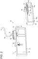
Fig. 2 is a perspective view of a case and a wiring unit that form the electrical junction box; -
Fig. 3 is a perspective view of the wiring unit; -
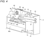
Fig. 4 is a perspective view of an upper portion of a housing provided with a path restricting wall; -
Fig. 5 is a front view of a part of a cable introduction portion of the electrical junction box as viewed from the attachment side to the battery pack; and -
Fig. 6 is a cross-sectional view taken along a line A-A inFig. 5 . - Hereinafter, an example of an embodiment according to the presently disclosed subject matter will be described with reference to the drawings.
Figs. 1A and 1B show an electrical junction box according to the present embodiment, in whichFig. 1A is a perspective view showing the electrical junction box as viewed from an attachment side to a battery pack, andFig. 1B is a perspective view showing the electrical junction box as viewed from a side opposite to the attachment side to the battery pack.Fig. 2 is a perspective view of a case and a wiring unit that form the electrical junction box. - As shown in
Figs. 1A, 1B , and2 , anelectrical junction box 10 according to the present embodiment includes acase 11 and awiring unit 12. Theelectrical junction box 10 is assembled to, for example, a battery pack mounted on a hybrid vehicle or an electric vehicle. - The
case 11 forming theelectrical junction box 10 is molded from, for example, aluminum or an aluminum alloy, and has anaccommodation recess 22 opened at an opening 21 on one side. Thewiring unit 12 is assembled to thecase 11 in a state of being accommodated in the accommodation recess 22 of thecase 11. - The
electrical junction box 10 is assembled to the battery pack by screwing a bolt (not shown) that is inserted into a bolt insertion hole (not shown) formed in thecase 11 into a screw hole of the battery pack and fastening the bolt. Further, when theelectrical junction box 10 is assembled to the battery pack, a space between the battery pack and thecase 11 is sealed by a packing (not shown) attached to an edge portion of theopening 21 of thecase 11. - The
case 11 is provided with asignal line connector 40 at a side portion at a center of thecase 11 in a longitudinal direction. For example, a connector of a wire harness including a signal line extending from a control unit (ECU) is connected to thesignal line connector 40. - The
signal line connector 40 includes aconnector housing 41 that accommodates a terminal (not shown) therein, and theconnector housing 41 is fastened and fixed to the side portion of thecase 11. Thesignal line connector 40 includes asignal cable 42 connected to a terminal provided inside theconnector housing 41, and thesignal cable 42 is drawn into thecase 11. - The
case 11 includes, at an upper portion thereof, acable introduction portion 15 to which a cable lead-inmember 50 is attached. In thecable introduction portion 15,cables member 50, and thesecables case 11 via the cable lead-inmember 50. For example, one of thecables cables member 50 and bundled, and are connected to a connector (not shown) for a seat heater as awire harness 53 for the seat heater. The seat heater is an auxiliary device. Thecables case 11 are connected to a power supply portion of the battery pack and an interlocking short terminal. -
Fig. 3 is a perspective view of the wiring unit. As shown inFig. 3 , thewiring unit 12 includes ahousing 60. Thehousing 60 is molded from an insulating synthetic resin. A positiveelectrode bus bar 61 and a negativeelectrode bus bar 62 are assembled to thehousing 60. For example, a power supply line of a wire harness extending from an inverter is connected to the positiveelectrode bus bar 61 and the negativeelectrode bus bar 62. - An electric and electronic component such as a ferrite or a fuse is assembled to an
accommodation space 60a inside thehousing 60. Further, an opening side of thehousing 60, to which the positiveelectrode bus bar 61, the negativeelectrode bus bar 62, the ferrite, and the fuse are assembled, is covered with a cover (not shown). - The
housing 60 of thewiring unit 12 is assembled and housed in the accommodation recess 22 of thecase 11 from the opening 21, and is fixed in this housed state with, for example, a bolt. - The positive
electrode bus bar 61 and the negativeelectrode bus bar 62 include, at end portions thereof, fasteningportions stud bolts housing 60 hasengagement grooves electrode bus bar 61 and the negativeelectrode bus bar 62 that are assembled to thehousing 60, the fasteningportions engagement grooves -
Fig. 4 is a perspective view of an upper portion of a housing provided with a path restricting wall.Fig. 5 is a front view of a part of a cable introduction portion of the electrical junction box as viewed from the attachment side to the battery pack.Fig. 6 is a cross-sectional view taken along a line A-A inFig. 5 . - As shown in
Figs. 4 to 6 , thehousing 60 forming thewiring unit 12 includes apath restricting wall 90. Thepath restricting wall 90 is formed integrally with the upper portion of thehousing 60. - The
path restricting wall 90 is provided in a vicinity of an inner side surface of thecase 11 below thecable introduction portion 15 to which the cable lead-inmember 50 in thecase 11 is attached and thecables case 11. Further, thepath restricting wall 90 is provided on a back side, which is a rear position with respect to thefastening portions electrode bus bar 61 and the negativeelectrode bus bar 62 that are engaged with theengagement grooves housing 60. - A rear surface of the
path restricting wall 90 is aguide surface 91. Theguide surface 91 is an inclined surface that is gradually inclined laterally toward the front of thehousing 60. - The
cable accommodation recess 22 from thecable introduction portion 15 of thecase 11 is restricted in a wiring direction thereof by thepath restricting wall 90 formed integrally with thehousing 60. Specifically, the wiring direction of thecables housing 60 by theguide surface 91 of thepath restricting wall 90. Accordingly, thecables fastening portions electrode bus bar 61 and the negativeelectrode bus bar 62 that are provided in front of thecable introduction portion 15. - In order to assemble the
electrical junction box 10 having the above-described structure, thehousing 60 of thewiring unit 12 is accommodated in theaccommodation recess 22 of thecase 11 and fastened to thecase 11 with bolts. Accordingly, thewiring unit 12 is fixed in a state of being accommodated in theaccommodation recess 22 of thecase 11. Accordingly, theelectrical junction box 10, in which thewiring unit 12 is assembled, is attained in theaccommodation recess 22 of thecase 11. - As described above, when the
housing 60 of thewiring unit 12 is assembled to theaccommodation recess 22 of thecase 11, thecables accommodation recess 22 from thecable introduction portion 15 of thecase 11 are pushed laterally by thepath restricting wall 90 formed integrally with thehousing 60. Further, thecables guide surface 91 of thepath restricting wall 90. Thepath restricting wall 90 of thehousing 60 is provided at a position where an upper edge portion of thepath restricting wall 90 is close to the inner side surface of thecase 11. Therefore, thecables path restricting wall 90 and an inner surface of thecase 11, to the front where thefastening portions electrode bus bar 61 and the negativeelectrode bus bar 62 are provided. - In order to assemble the
electrical junction box 10 assembled in this manner to the battery pack, a connector or a terminal (not shown) provided at end portions of thesignal cable 42 and thecables fastening portions electrode bus bar 61 and the negativeelectrode bus bar 62 with nuts. At this time, thecables case 11 from thecable introduction portion 15 are wired at positions away from thefastening portions electrode bus bar 61 and the negativeelectrode bus bar 62. Therefore, when the terminals of the power cables on the battery pack side are fastened to thefastening portions cables cables - The
electrical junction box 10 is assembled to the battery pack in a state of being sealed by a packing, by fastening thecase 11 to the battery pack with bolts after wiring with the battery pack. - As described above, according to the
electrical junction box 10 in the present embodiment, thehousing 60 of thewiring unit 12 assembled into theaccommodation recess 22 of thecase 11 includes thepath restricting wall 90 that restricts the wiring direction of thecables accommodation recess 22 of thecase 11. Therefore, thecables accommodation recess 22 of thecase 11 can be wired along a preset path by restricting the wiring direction in a narrow space. - Accordingly, it is possible to prevent interference between the drawn
cables fastening portions electrode bus bar 61 and the negativeelectrode bus bar 62, it is possible to prevent thecables accommodation recess 22 of thecase 11 from being bitten to the fastening positions. Accordingly, it is possible to improve internal wiring workability. - Since the
path restricting wall 90 has theguide surface 91 that guides thecables cables accommodation recess 22 of thecase 11 can be guided by theguide surface 91 of thepath restricting wall 90, and can be wired without difficulty along the preset wiring path. - According to the
electrical junction box 10, thecables case 11 can be smoothly wired to the battery pack side and assembled to the battery pack. - While the presently disclosed subject matter has been described with reference to certain exemplary embodiments thereof, the scope of the presently disclosed subject matter is not limited to the exemplary embodiments described above, and it will be understood by those skilled in the art that various changes and modifications may be made therein without departing from the scope of the presently disclosed subject matter as defined by the appended claims.
- According to an aspect of the embodiments described above, an electrical junction box (10) is configured such that an electric or electronic component (for example, a positive
electrode bus bar 61, a negativeelectrode bus bar 62, a ferrite, and a fuse) is mounted thereon. The electrical junction box (10) includes a case (11) having an accommodation recess (22), a housing (60) configured such that the electric or electronic component (the positiveelectrode bus bar 61, the negativeelectrode bus bar 62, the ferrite, and the fuse) is held therein and configured to be attached in the accommodation recess (22) and a cable (51, 52) configured to be drawn into the accommodation recess (22). The housing (60) includes a path restricting wall (90) configured to restrict a wiring direction of the cable (51, 52). - According to the electrical junction box having the above-described configuration, the housing assembled into the accommodation recess of the case includes the path restricting wall that restricts the wiring direction of the cable drawn into the accommodation recess of the case. Therefore, the cables drawn into the accommodation recess of the case can be wired along a preset path by restricting the wiring direction in a narrow space. Accordingly, it is possible to prevent interference between the drawn cables and the electric and electronic component and the like while achieving a reduction in size. For example, when the electric wire is fastened to the fastening portion of the bus bar, it is possible to prevent the cable drawn into the accommodation recess of the case from being bitten to the fastening position. Accordingly, it is possible to improve internal wiring workability.
- The path restricting wall (90) may have a guide surface (91) configured to guide the cable (51, 52) along a predetermined wiring path.
- With this configuration, the cable drawn into the accommodation recess of the case can be guided by the guide surface of the path restricting wall, and can be wired without difficulty along the preset wiring path.
- The case (11) may be configured such that an opening side of the accommodation recess (22) is attached to a battery pack, and the cable (51, 52) may be configured to be wired to the battery pack.
- With this configuration, the cable that is wired without difficulty in the case can be smoothly wired to the battery pack side and assembled to the battery pack.
Claims (3)
- An electrical junction box (10) configured such that an electric or electronic component (61, 62) is mounted thereon, the electrical junction box (10) comprising:a case (11) having an accommodation recess (22);a housing (60) configured such that the electric or electronic component (61, 62) is held therein and configured to be attached in the accommodation recess (22); anda cable (51, 52) configured to be drawn into the accommodation recess (22),wherein the housing (60) includes a path restricting wall (90) configured to restrict a wiring direction of the cable (51, 52).
- The electrical junction box according to claim 1,
wherein the path restricting wall (90) has a guide surface (91) configured to guide the cable (51, 52) along a predetermined wiring path. - The electrical junction box according to claim 1 or 2,wherein the case (11) is configured such that an opening side of the accommodation recess (22) is attached to a battery pack, andwherein the cable (51, 52) is configured to be wired to the battery pack.
Applications Claiming Priority (1)
| Application Number | Priority Date | Filing Date | Title |
|---|---|---|---|
| JP2021140018A JP7410093B2 (en) | 2021-08-30 | 2021-08-30 | electrical junction box |
Publications (2)
| Publication Number | Publication Date |
|---|---|
| EP4140825A1 true EP4140825A1 (en) | 2023-03-01 |
| EP4140825B1 EP4140825B1 (en) | 2023-10-18 |
Family
ID=83152017
Family Applications (1)
| Application Number | Title | Priority Date | Filing Date |
|---|---|---|---|
| EP22192852.6A Active EP4140825B1 (en) | 2021-08-30 | 2022-08-30 | Electrical junction box |
Country Status (4)
| Country | Link |
|---|---|
| US (1) | US11804701B2 (en) |
| EP (1) | EP4140825B1 (en) |
| JP (1) | JP7410093B2 (en) |
| CN (1) | CN115733106B (en) |
Families Citing this family (1)
| Publication number | Priority date | Publication date | Assignee | Title |
|---|---|---|---|---|
| US12119465B2 (en) * | 2022-11-14 | 2024-10-15 | Archer Aviation Inc. | Heat exchanger assemblies and cooling systems for evtol aircraft |
Citations (4)
| Publication number | Priority date | Publication date | Assignee | Title |
|---|---|---|---|---|
| US20060030176A1 (en) * | 2004-08-04 | 2006-02-09 | Yazaki Corporation | Arrangement structure of electric junction box |
| US20120048617A1 (en) * | 2010-08-25 | 2012-03-01 | Panasonic Electric Works Co., Ltd. | Power supply control device |
| US20120249079A1 (en) * | 2010-12-07 | 2012-10-04 | Bennett Scott K | Compliant tip thermistor for an energy storage system |
| US20170006718A1 (en) * | 2014-01-22 | 2017-01-05 | Sumitomo Wiring Systems, Ltd. | Switching device |
Family Cites Families (13)
| Publication number | Priority date | Publication date | Assignee | Title |
|---|---|---|---|---|
| JPH0741951U (en) * | 1993-12-20 | 1995-07-21 | 住友電装株式会社 | High voltage fuse box |
| JP3845263B2 (en) | 2001-03-07 | 2006-11-15 | 矢崎総業株式会社 | Protective cover and fuse box |
| EP1239506B1 (en) * | 2001-03-07 | 2012-04-25 | Yazaki Corporation | Protective cover and fuse box |
| JP3994810B2 (en) * | 2002-07-09 | 2007-10-24 | 住友電装株式会社 | Box with built-in battery fuse |
| JP5576675B2 (en) | 2010-02-23 | 2014-08-20 | パナソニック株式会社 | Power supply control device |
| US8911253B2 (en) | 2011-06-13 | 2014-12-16 | Tyco Electronics Corporation | Receptacle contact |
| JP5953104B2 (en) * | 2012-05-02 | 2016-07-20 | 矢崎総業株式会社 | Electrical junction box |
| CN105810867B (en) * | 2016-05-10 | 2017-05-17 | 国防科学技术大学 | Solid-state polymer lithium battery pack and preparation method thereof |
| IT201600090442A1 (en) * | 2016-09-07 | 2018-03-07 | Johnson Electric Asti S R L | Electrical connection assembly for an electric motor, particularly for a brushless motor vehicle motor. |
| JP6490729B2 (en) * | 2017-03-22 | 2019-03-27 | 矢崎総業株式会社 | Electrical junction box |
| JP2019067574A (en) * | 2017-09-29 | 2019-04-25 | 矢崎総業株式会社 | Tuning fork terminal and electric connection box |
| JP6936970B2 (en) * | 2017-10-16 | 2021-09-22 | 住友電装株式会社 | Wire harness connection structure to the circuit inside the housing |
| JP7183945B2 (en) * | 2019-05-15 | 2022-12-06 | 住友電装株式会社 | electric junction box |
-
2021
- 2021-08-30 JP JP2021140018A patent/JP7410093B2/en active Active
-
2022
- 2022-08-26 US US17/896,654 patent/US11804701B2/en active Active
- 2022-08-30 CN CN202211058178.2A patent/CN115733106B/en active Active
- 2022-08-30 EP EP22192852.6A patent/EP4140825B1/en active Active
Patent Citations (5)
| Publication number | Priority date | Publication date | Assignee | Title |
|---|---|---|---|---|
| US20060030176A1 (en) * | 2004-08-04 | 2006-02-09 | Yazaki Corporation | Arrangement structure of electric junction box |
| JP2006044443A (en) | 2004-08-04 | 2006-02-16 | Yazaki Corp | Electrical junction box layout |
| US20120048617A1 (en) * | 2010-08-25 | 2012-03-01 | Panasonic Electric Works Co., Ltd. | Power supply control device |
| US20120249079A1 (en) * | 2010-12-07 | 2012-10-04 | Bennett Scott K | Compliant tip thermistor for an energy storage system |
| US20170006718A1 (en) * | 2014-01-22 | 2017-01-05 | Sumitomo Wiring Systems, Ltd. | Switching device |
Also Published As
| Publication number | Publication date |
|---|---|
| JP2023033995A (en) | 2023-03-13 |
| JP7410093B2 (en) | 2024-01-09 |
| US11804701B2 (en) | 2023-10-31 |
| CN115733106A (en) | 2023-03-03 |
| US20230068924A1 (en) | 2023-03-02 |
| EP4140825B1 (en) | 2023-10-18 |
| CN115733106B (en) | 2025-09-05 |
Similar Documents
| Publication | Publication Date | Title |
|---|---|---|
| US10661668B2 (en) | Power conversion apparatus and junction box | |
| US9006939B2 (en) | Wiring harness and a method of providing wiring structure of the same | |
| JP4650691B2 (en) | Electrical connection structure | |
| JP5140414B2 (en) | Corrugated clamp | |
| US9324983B2 (en) | Battery module for vehicle | |
| CN102447083B (en) | Electric storage device | |
| US10391955B2 (en) | Electrical junction box | |
| JP2016192359A (en) | connector | |
| WO2014192859A1 (en) | Bus bar module and power supply device | |
| WO2014192858A1 (en) | Bus bar module and power supply device | |
| EP4140825B1 (en) | Electrical junction box | |
| US9685905B2 (en) | Terminal box and solar cell module | |
| JP2025061741A (en) | Charging connector | |
| CN104093603A (en) | Protector and wire harness | |
| JP3638103B2 (en) | Wire lead-out structure of wire protector | |
| JP2012235623A (en) | Protector | |
| JP2019204596A (en) | Wiring module | |
| JP2018050456A (en) | Electrical connection structure | |
| JP7512992B2 (en) | connector | |
| US20240300430A1 (en) | Cable attachment structure and cable attachment method | |
| JPH035077Y2 (en) | ||
| JP7107659B2 (en) | electric junction box | |
| JP2024072677A (en) | Electrical Junction Box | |
| JP2024089213A (en) | Electrical Junction Box | |
| CN115693268A (en) | Charging connector |
Legal Events
| Date | Code | Title | Description |
|---|---|---|---|
| PUAI | Public reference made under article 153(3) epc to a published international application that has entered the european phase |
Free format text: ORIGINAL CODE: 0009012 |
|
| STAA | Information on the status of an ep patent application or granted ep patent |
Free format text: STATUS: REQUEST FOR EXAMINATION WAS MADE |
|
| 17P | Request for examination filed |
Effective date: 20220830 |
|
| AK | Designated contracting states |
Kind code of ref document: A1 Designated state(s): AL AT BE BG CH CY CZ DE DK EE ES FI FR GB GR HR HU IE IS IT LI LT LU LV MC MK MT NL NO PL PT RO RS SE SI SK SM TR |
|
| RAP3 | Party data changed (applicant data changed or rights of an application transferred) |
Owner name: YAZAKI CORPORATION |
|
| GRAP | Despatch of communication of intention to grant a patent |
Free format text: ORIGINAL CODE: EPIDOSNIGR1 |
|
| RIC1 | Information provided on ipc code assigned before grant |
Ipc: B60R 16/02 20060101ALI20230525BHEP Ipc: H05K 5/02 20060101ALI20230525BHEP Ipc: H02G 3/08 20060101ALI20230525BHEP Ipc: H02B 1/48 20060101ALI20230525BHEP Ipc: B60R 16/023 20060101AFI20230525BHEP |
|
| STAA | Information on the status of an ep patent application or granted ep patent |
Free format text: STATUS: GRANT OF PATENT IS INTENDED |
|
| INTG | Intention to grant announced |
Effective date: 20230706 |
|
| GRAS | Grant fee paid |
Free format text: ORIGINAL CODE: EPIDOSNIGR3 |
|
| GRAA | (expected) grant |
Free format text: ORIGINAL CODE: 0009210 |
|
| STAA | Information on the status of an ep patent application or granted ep patent |
Free format text: STATUS: THE PATENT HAS BEEN GRANTED |
|
| AK | Designated contracting states |
Kind code of ref document: B1 Designated state(s): AL AT BE BG CH CY CZ DE DK EE ES FI FR GB GR HR HU IE IS IT LI LT LU LV MC MK MT NL NO PL PT RO RS SE SI SK SM TR |
|
| REG | Reference to a national code |
Ref country code: GB Ref legal event code: FG4D |
|
| REG | Reference to a national code |
Ref country code: CH Ref legal event code: EP |
|
| REG | Reference to a national code |
Ref country code: DE Ref legal event code: R096 Ref document number: 602022000728 Country of ref document: DE |
|
| REG | Reference to a national code |
Ref country code: IE Ref legal event code: FG4D |
|
| REG | Reference to a national code |
Ref country code: LT Ref legal event code: MG9D |
|
| REG | Reference to a national code |
Ref country code: NL Ref legal event code: MP Effective date: 20231018 |
|
| REG | Reference to a national code |
Ref country code: AT Ref legal event code: MK05 Ref document number: 1622173 Country of ref document: AT Kind code of ref document: T Effective date: 20231018 |
|
| PG25 | Lapsed in a contracting state [announced via postgrant information from national office to epo] |
Ref country code: NL Free format text: LAPSE BECAUSE OF FAILURE TO SUBMIT A TRANSLATION OF THE DESCRIPTION OR TO PAY THE FEE WITHIN THE PRESCRIBED TIME-LIMIT Effective date: 20231018 |
|
| PG25 | Lapsed in a contracting state [announced via postgrant information from national office to epo] |
Ref country code: GR Free format text: LAPSE BECAUSE OF FAILURE TO SUBMIT A TRANSLATION OF THE DESCRIPTION OR TO PAY THE FEE WITHIN THE PRESCRIBED TIME-LIMIT Effective date: 20240119 |
|
| PG25 | Lapsed in a contracting state [announced via postgrant information from national office to epo] |
Ref country code: IS Free format text: LAPSE BECAUSE OF FAILURE TO SUBMIT A TRANSLATION OF THE DESCRIPTION OR TO PAY THE FEE WITHIN THE PRESCRIBED TIME-LIMIT Effective date: 20240218 |
|
| PG25 | Lapsed in a contracting state [announced via postgrant information from national office to epo] |
Ref country code: LT Free format text: LAPSE BECAUSE OF FAILURE TO SUBMIT A TRANSLATION OF THE DESCRIPTION OR TO PAY THE FEE WITHIN THE PRESCRIBED TIME-LIMIT Effective date: 20231018 |
|
| PG25 | Lapsed in a contracting state [announced via postgrant information from national office to epo] |
Ref country code: AT Free format text: LAPSE BECAUSE OF FAILURE TO SUBMIT A TRANSLATION OF THE DESCRIPTION OR TO PAY THE FEE WITHIN THE PRESCRIBED TIME-LIMIT Effective date: 20231018 |
|
| PG25 | Lapsed in a contracting state [announced via postgrant information from national office to epo] |
Ref country code: ES Free format text: LAPSE BECAUSE OF FAILURE TO SUBMIT A TRANSLATION OF THE DESCRIPTION OR TO PAY THE FEE WITHIN THE PRESCRIBED TIME-LIMIT Effective date: 20231018 |
|
| PG25 | Lapsed in a contracting state [announced via postgrant information from national office to epo] |
Ref country code: LT Free format text: LAPSE BECAUSE OF FAILURE TO SUBMIT A TRANSLATION OF THE DESCRIPTION OR TO PAY THE FEE WITHIN THE PRESCRIBED TIME-LIMIT Effective date: 20231018 Ref country code: IS Free format text: LAPSE BECAUSE OF FAILURE TO SUBMIT A TRANSLATION OF THE DESCRIPTION OR TO PAY THE FEE WITHIN THE PRESCRIBED TIME-LIMIT Effective date: 20240218 Ref country code: GR Free format text: LAPSE BECAUSE OF FAILURE TO SUBMIT A TRANSLATION OF THE DESCRIPTION OR TO PAY THE FEE WITHIN THE PRESCRIBED TIME-LIMIT Effective date: 20240119 Ref country code: ES Free format text: LAPSE BECAUSE OF FAILURE TO SUBMIT A TRANSLATION OF THE DESCRIPTION OR TO PAY THE FEE WITHIN THE PRESCRIBED TIME-LIMIT Effective date: 20231018 Ref country code: BG Free format text: LAPSE BECAUSE OF FAILURE TO SUBMIT A TRANSLATION OF THE DESCRIPTION OR TO PAY THE FEE WITHIN THE PRESCRIBED TIME-LIMIT Effective date: 20240118 Ref country code: AT Free format text: LAPSE BECAUSE OF FAILURE TO SUBMIT A TRANSLATION OF THE DESCRIPTION OR TO PAY THE FEE WITHIN THE PRESCRIBED TIME-LIMIT Effective date: 20231018 Ref country code: PT Free format text: LAPSE BECAUSE OF FAILURE TO SUBMIT A TRANSLATION OF THE DESCRIPTION OR TO PAY THE FEE WITHIN THE PRESCRIBED TIME-LIMIT Effective date: 20240219 |
|
| PG25 | Lapsed in a contracting state [announced via postgrant information from national office to epo] |
Ref country code: SE Free format text: LAPSE BECAUSE OF FAILURE TO SUBMIT A TRANSLATION OF THE DESCRIPTION OR TO PAY THE FEE WITHIN THE PRESCRIBED TIME-LIMIT Effective date: 20231018 Ref country code: RS Free format text: LAPSE BECAUSE OF FAILURE TO SUBMIT A TRANSLATION OF THE DESCRIPTION OR TO PAY THE FEE WITHIN THE PRESCRIBED TIME-LIMIT Effective date: 20231018 Ref country code: PL Free format text: LAPSE BECAUSE OF FAILURE TO SUBMIT A TRANSLATION OF THE DESCRIPTION OR TO PAY THE FEE WITHIN THE PRESCRIBED TIME-LIMIT Effective date: 20231018 Ref country code: NO Free format text: LAPSE BECAUSE OF FAILURE TO SUBMIT A TRANSLATION OF THE DESCRIPTION OR TO PAY THE FEE WITHIN THE PRESCRIBED TIME-LIMIT Effective date: 20240118 Ref country code: LV Free format text: LAPSE BECAUSE OF FAILURE TO SUBMIT A TRANSLATION OF THE DESCRIPTION OR TO PAY THE FEE WITHIN THE PRESCRIBED TIME-LIMIT Effective date: 20231018 Ref country code: HR Free format text: LAPSE BECAUSE OF FAILURE TO SUBMIT A TRANSLATION OF THE DESCRIPTION OR TO PAY THE FEE WITHIN THE PRESCRIBED TIME-LIMIT Effective date: 20231018 |
|
| PG25 | Lapsed in a contracting state [announced via postgrant information from national office to epo] |
Ref country code: DK Free format text: LAPSE BECAUSE OF FAILURE TO SUBMIT A TRANSLATION OF THE DESCRIPTION OR TO PAY THE FEE WITHIN THE PRESCRIBED TIME-LIMIT Effective date: 20231018 |
|
| REG | Reference to a national code |
Ref country code: DE Ref legal event code: R097 Ref document number: 602022000728 Country of ref document: DE |
|
| PG25 | Lapsed in a contracting state [announced via postgrant information from national office to epo] |
Ref country code: CZ Free format text: LAPSE BECAUSE OF FAILURE TO SUBMIT A TRANSLATION OF THE DESCRIPTION OR TO PAY THE FEE WITHIN THE PRESCRIBED TIME-LIMIT Effective date: 20231018 |
|
| PG25 | Lapsed in a contracting state [announced via postgrant information from national office to epo] |
Ref country code: SK Free format text: LAPSE BECAUSE OF FAILURE TO SUBMIT A TRANSLATION OF THE DESCRIPTION OR TO PAY THE FEE WITHIN THE PRESCRIBED TIME-LIMIT Effective date: 20231018 |
|
| PG25 | Lapsed in a contracting state [announced via postgrant information from national office to epo] |
Ref country code: SM Free format text: LAPSE BECAUSE OF FAILURE TO SUBMIT A TRANSLATION OF THE DESCRIPTION OR TO PAY THE FEE WITHIN THE PRESCRIBED TIME-LIMIT Effective date: 20231018 Ref country code: SK Free format text: LAPSE BECAUSE OF FAILURE TO SUBMIT A TRANSLATION OF THE DESCRIPTION OR TO PAY THE FEE WITHIN THE PRESCRIBED TIME-LIMIT Effective date: 20231018 Ref country code: RO Free format text: LAPSE BECAUSE OF FAILURE TO SUBMIT A TRANSLATION OF THE DESCRIPTION OR TO PAY THE FEE WITHIN THE PRESCRIBED TIME-LIMIT Effective date: 20231018 Ref country code: IT Free format text: LAPSE BECAUSE OF FAILURE TO SUBMIT A TRANSLATION OF THE DESCRIPTION OR TO PAY THE FEE WITHIN THE PRESCRIBED TIME-LIMIT Effective date: 20231018 Ref country code: EE Free format text: LAPSE BECAUSE OF FAILURE TO SUBMIT A TRANSLATION OF THE DESCRIPTION OR TO PAY THE FEE WITHIN THE PRESCRIBED TIME-LIMIT Effective date: 20231018 Ref country code: DK Free format text: LAPSE BECAUSE OF FAILURE TO SUBMIT A TRANSLATION OF THE DESCRIPTION OR TO PAY THE FEE WITHIN THE PRESCRIBED TIME-LIMIT Effective date: 20231018 Ref country code: CZ Free format text: LAPSE BECAUSE OF FAILURE TO SUBMIT A TRANSLATION OF THE DESCRIPTION OR TO PAY THE FEE WITHIN THE PRESCRIBED TIME-LIMIT Effective date: 20231018 |
|
| PLBE | No opposition filed within time limit |
Free format text: ORIGINAL CODE: 0009261 |
|
| STAA | Information on the status of an ep patent application or granted ep patent |
Free format text: STATUS: NO OPPOSITION FILED WITHIN TIME LIMIT |
|
| 26N | No opposition filed |
Effective date: 20240719 |
|
| PG25 | Lapsed in a contracting state [announced via postgrant information from national office to epo] |
Ref country code: SI Free format text: LAPSE BECAUSE OF FAILURE TO SUBMIT A TRANSLATION OF THE DESCRIPTION OR TO PAY THE FEE WITHIN THE PRESCRIBED TIME-LIMIT Effective date: 20231018 |
|
| PG25 | Lapsed in a contracting state [announced via postgrant information from national office to epo] |
Ref country code: SI Free format text: LAPSE BECAUSE OF FAILURE TO SUBMIT A TRANSLATION OF THE DESCRIPTION OR TO PAY THE FEE WITHIN THE PRESCRIBED TIME-LIMIT Effective date: 20231018 |
|
| REG | Reference to a national code |
Ref country code: DE Ref legal event code: R119 Ref document number: 602022000728 Country of ref document: DE |
|
| PG25 | Lapsed in a contracting state [announced via postgrant information from national office to epo] |
Ref country code: LU Free format text: LAPSE BECAUSE OF NON-PAYMENT OF DUE FEES Effective date: 20240830 |
|
| PG25 | Lapsed in a contracting state [announced via postgrant information from national office to epo] |
Ref country code: MC Free format text: LAPSE BECAUSE OF FAILURE TO SUBMIT A TRANSLATION OF THE DESCRIPTION OR TO PAY THE FEE WITHIN THE PRESCRIBED TIME-LIMIT Effective date: 20231018 |
|
| REG | Reference to a national code |
Ref country code: BE Ref legal event code: MM Effective date: 20240831 |
|
| PG25 | Lapsed in a contracting state [announced via postgrant information from national office to epo] |
Ref country code: DE Free format text: LAPSE BECAUSE OF NON-PAYMENT OF DUE FEES Effective date: 20250301 |
|
| PG25 | Lapsed in a contracting state [announced via postgrant information from national office to epo] |
Ref country code: BE Free format text: LAPSE BECAUSE OF NON-PAYMENT OF DUE FEES Effective date: 20240831 |
|
| PG25 | Lapsed in a contracting state [announced via postgrant information from national office to epo] |
Ref country code: IE Free format text: LAPSE BECAUSE OF NON-PAYMENT OF DUE FEES Effective date: 20240830 |
|
| PG25 | Lapsed in a contracting state [announced via postgrant information from national office to epo] |
Ref country code: FI Free format text: LAPSE BECAUSE OF FAILURE TO SUBMIT A TRANSLATION OF THE DESCRIPTION OR TO PAY THE FEE WITHIN THE PRESCRIBED TIME-LIMIT Effective date: 20231019 |
|
| PGFP | Annual fee paid to national office [announced via postgrant information from national office to epo] |
Ref country code: FR Payment date: 20250703 Year of fee payment: 4 |
|
| PG25 | Lapsed in a contracting state [announced via postgrant information from national office to epo] |
Ref country code: CY Free format text: LAPSE BECAUSE OF FAILURE TO SUBMIT A TRANSLATION OF THE DESCRIPTION OR TO PAY THE FEE WITHIN THE PRESCRIBED TIME-LIMIT; INVALID AB INITIO Effective date: 20220830 |
|
| PG25 | Lapsed in a contracting state [announced via postgrant information from national office to epo] |
Ref country code: HU Free format text: LAPSE BECAUSE OF FAILURE TO SUBMIT A TRANSLATION OF THE DESCRIPTION OR TO PAY THE FEE WITHIN THE PRESCRIBED TIME-LIMIT; INVALID AB INITIO Effective date: 20220830 |
|
| REG | Reference to a national code |
Ref country code: CH Ref legal event code: H13 Free format text: ST27 STATUS EVENT CODE: U-0-0-H10-H13 (AS PROVIDED BY THE NATIONAL OFFICE) Effective date: 20260324 |
|
| PG25 | Lapsed in a contracting state [announced via postgrant information from national office to epo] |
Ref country code: CH Free format text: LAPSE BECAUSE OF NON-PAYMENT OF DUE FEES Effective date: 20250831 |