EP4140800A1 - Electric vehicle charging arrangement with pre-arging and method for charging an electric vehicle - Google Patents
Electric vehicle charging arrangement with pre-arging and method for charging an electric vehicle Download PDFInfo
- Publication number
- EP4140800A1 EP4140800A1 EP21193847.7A EP21193847A EP4140800A1 EP 4140800 A1 EP4140800 A1 EP 4140800A1 EP 21193847 A EP21193847 A EP 21193847A EP 4140800 A1 EP4140800 A1 EP 4140800A1
- Authority
- EP
- European Patent Office
- Prior art keywords
- line
- electric vehicle
- contactor
- power module
- output
- Prior art date
- Legal status (The legal status is an assumption and is not a legal conclusion. Google has not performed a legal analysis and makes no representation as to the accuracy of the status listed.)
- Pending
Links
Images

Classifications
-
- B—PERFORMING OPERATIONS; TRANSPORTING
- B60—VEHICLES IN GENERAL
- B60L—PROPULSION OF ELECTRICALLY-PROPELLED VEHICLES; SUPPLYING ELECTRIC POWER FOR AUXILIARY EQUIPMENT OF ELECTRICALLY-PROPELLED VEHICLES; ELECTRODYNAMIC BRAKE SYSTEMS FOR VEHICLES IN GENERAL; MAGNETIC SUSPENSION OR LEVITATION FOR VEHICLES; MONITORING OPERATING VARIABLES OF ELECTRICALLY-PROPELLED VEHICLES; ELECTRIC SAFETY DEVICES FOR ELECTRICALLY-PROPELLED VEHICLES
- B60L53/00—Methods of charging batteries, specially adapted for electric vehicles; Charging stations or on-board charging equipment therefor; Exchange of energy storage elements in electric vehicles
- B60L53/10—Methods of charging batteries, specially adapted for electric vehicles; Charging stations or on-board charging equipment therefor; Exchange of energy storage elements in electric vehicles characterised by the energy transfer between the charging station and the vehicle
- B60L53/11—DC charging controlled by the charging station, e.g. mode 4
-
- B—PERFORMING OPERATIONS; TRANSPORTING
- B60—VEHICLES IN GENERAL
- B60L—PROPULSION OF ELECTRICALLY-PROPELLED VEHICLES; SUPPLYING ELECTRIC POWER FOR AUXILIARY EQUIPMENT OF ELECTRICALLY-PROPELLED VEHICLES; ELECTRODYNAMIC BRAKE SYSTEMS FOR VEHICLES IN GENERAL; MAGNETIC SUSPENSION OR LEVITATION FOR VEHICLES; MONITORING OPERATING VARIABLES OF ELECTRICALLY-PROPELLED VEHICLES; ELECTRIC SAFETY DEVICES FOR ELECTRICALLY-PROPELLED VEHICLES
- B60L3/00—Electric devices on electrically-propelled vehicles for safety purposes; Monitoring operating variables, e.g. speed, deceleration or energy consumption
- B60L3/0023—Detecting, eliminating, remedying or compensating for drive train abnormalities, e.g. failures within the drive train
- B60L3/0046—Detecting, eliminating, remedying or compensating for drive train abnormalities, e.g. failures within the drive train relating to electric energy storage systems, e.g. batteries or capacitors
-
- B—PERFORMING OPERATIONS; TRANSPORTING
- B60—VEHICLES IN GENERAL
- B60L—PROPULSION OF ELECTRICALLY-PROPELLED VEHICLES; SUPPLYING ELECTRIC POWER FOR AUXILIARY EQUIPMENT OF ELECTRICALLY-PROPELLED VEHICLES; ELECTRODYNAMIC BRAKE SYSTEMS FOR VEHICLES IN GENERAL; MAGNETIC SUSPENSION OR LEVITATION FOR VEHICLES; MONITORING OPERATING VARIABLES OF ELECTRICALLY-PROPELLED VEHICLES; ELECTRIC SAFETY DEVICES FOR ELECTRICALLY-PROPELLED VEHICLES
- B60L53/00—Methods of charging batteries, specially adapted for electric vehicles; Charging stations or on-board charging equipment therefor; Exchange of energy storage elements in electric vehicles
- B60L53/10—Methods of charging batteries, specially adapted for electric vehicles; Charging stations or on-board charging equipment therefor; Exchange of energy storage elements in electric vehicles characterised by the energy transfer between the charging station and the vehicle
- B60L53/14—Conductive energy transfer
-
- H—ELECTRICITY
- H02—GENERATION; CONVERSION OR DISTRIBUTION OF ELECTRIC POWER
- H02J—CIRCUIT ARRANGEMENTS OR SYSTEMS FOR SUPPLYING OR DISTRIBUTING ELECTRIC POWER; SYSTEMS FOR STORING ELECTRIC ENERGY
- H02J7/00—Circuit arrangements for charging or depolarising batteries or for supplying loads from batteries
- H02J7/0069—Charging or discharging for charge maintenance, battery initiation or rejuvenation
-
- H—ELECTRICITY
- H02—GENERATION; CONVERSION OR DISTRIBUTION OF ELECTRIC POWER
- H02M—APPARATUS FOR CONVERSION BETWEEN AC AND AC, BETWEEN AC AND DC, OR BETWEEN DC AND DC, AND FOR USE WITH MAINS OR SIMILAR POWER SUPPLY SYSTEMS; CONVERSION OF DC OR AC INPUT POWER INTO SURGE OUTPUT POWER; CONTROL OR REGULATION THEREOF
- H02M1/00—Details of apparatus for conversion
- H02M1/32—Means for protecting converters other than automatic disconnection
-
- H—ELECTRICITY
- H02—GENERATION; CONVERSION OR DISTRIBUTION OF ELECTRIC POWER
- H02M—APPARATUS FOR CONVERSION BETWEEN AC AND AC, BETWEEN AC AND DC, OR BETWEEN DC AND DC, AND FOR USE WITH MAINS OR SIMILAR POWER SUPPLY SYSTEMS; CONVERSION OF DC OR AC INPUT POWER INTO SURGE OUTPUT POWER; CONTROL OR REGULATION THEREOF
- H02M1/00—Details of apparatus for conversion
- H02M1/36—Means for starting or stopping converters
-
- Y—GENERAL TAGGING OF NEW TECHNOLOGICAL DEVELOPMENTS; GENERAL TAGGING OF CROSS-SECTIONAL TECHNOLOGIES SPANNING OVER SEVERAL SECTIONS OF THE IPC; TECHNICAL SUBJECTS COVERED BY FORMER USPC CROSS-REFERENCE ART COLLECTIONS [XRACs] AND DIGESTS
- Y02—TECHNOLOGIES OR APPLICATIONS FOR MITIGATION OR ADAPTATION AGAINST CLIMATE CHANGE
- Y02T—CLIMATE CHANGE MITIGATION TECHNOLOGIES RELATED TO TRANSPORTATION
- Y02T10/00—Road transport of goods or passengers
- Y02T10/60—Other road transportation technologies with climate change mitigation effect
- Y02T10/70—Energy storage systems for electromobility, e.g. batteries
-
- Y—GENERAL TAGGING OF NEW TECHNOLOGICAL DEVELOPMENTS; GENERAL TAGGING OF CROSS-SECTIONAL TECHNOLOGIES SPANNING OVER SEVERAL SECTIONS OF THE IPC; TECHNICAL SUBJECTS COVERED BY FORMER USPC CROSS-REFERENCE ART COLLECTIONS [XRACs] AND DIGESTS
- Y02—TECHNOLOGIES OR APPLICATIONS FOR MITIGATION OR ADAPTATION AGAINST CLIMATE CHANGE
- Y02T—CLIMATE CHANGE MITIGATION TECHNOLOGIES RELATED TO TRANSPORTATION
- Y02T10/00—Road transport of goods or passengers
- Y02T10/60—Other road transportation technologies with climate change mitigation effect
- Y02T10/7072—Electromobility specific charging systems or methods for batteries, ultracapacitors, supercapacitors or double-layer capacitors
-
- Y—GENERAL TAGGING OF NEW TECHNOLOGICAL DEVELOPMENTS; GENERAL TAGGING OF CROSS-SECTIONAL TECHNOLOGIES SPANNING OVER SEVERAL SECTIONS OF THE IPC; TECHNICAL SUBJECTS COVERED BY FORMER USPC CROSS-REFERENCE ART COLLECTIONS [XRACs] AND DIGESTS
- Y02—TECHNOLOGIES OR APPLICATIONS FOR MITIGATION OR ADAPTATION AGAINST CLIMATE CHANGE
- Y02T—CLIMATE CHANGE MITIGATION TECHNOLOGIES RELATED TO TRANSPORTATION
- Y02T90/00—Enabling technologies or technologies with a potential or indirect contribution to GHG emissions mitigation
- Y02T90/10—Technologies relating to charging of electric vehicles
- Y02T90/12—Electric charging stations
-
- Y—GENERAL TAGGING OF NEW TECHNOLOGICAL DEVELOPMENTS; GENERAL TAGGING OF CROSS-SECTIONAL TECHNOLOGIES SPANNING OVER SEVERAL SECTIONS OF THE IPC; TECHNICAL SUBJECTS COVERED BY FORMER USPC CROSS-REFERENCE ART COLLECTIONS [XRACs] AND DIGESTS
- Y02—TECHNOLOGIES OR APPLICATIONS FOR MITIGATION OR ADAPTATION AGAINST CLIMATE CHANGE
- Y02T—CLIMATE CHANGE MITIGATION TECHNOLOGIES RELATED TO TRANSPORTATION
- Y02T90/00—Enabling technologies or technologies with a potential or indirect contribution to GHG emissions mitigation
- Y02T90/10—Technologies relating to charging of electric vehicles
- Y02T90/14—Plug-in electric vehicles
Definitions
- the invention relates to an electric vehicle charging arrangement for charging an electric vehicle, comprising an electric vehicle supply equipment. Furthermore, the invention relates to a method for charging an electric vehicle by an electric vehicle charging arrangement.
- Such an electric vehicle charging arrangement comprises a power module configured for providing electrical energy to charge the electric vehicle and an output configured for connecting the power module to the electric vehicle for charging the electric vehicle.
- a direct current (DC) bus with a DC+ line and a DC-line is provided between and connected to the power module and the output and configured for transporting electric energy from the power module to the output.
- Each of the DC+ line and the DC- line is provided with a contactor configured for selectively allowing a current flow from the power module to the output.
- a precharge circuit having a precharge resistor, is provided in parallel to the contactor of one of the DC+ line or the DC- line.
- precharging of the output of the electric vehicle supply equipment Before starting the charging of an electric vehicle after connecting the electric vehicle to the electric vehicle supply equipment, precharging of the output of the electric vehicle supply equipment has to be performed.
- the vehicle battery of the electric vehicle is not connected to the DC bus yet, because the contactors of the DC+ line and the DC- line are in the open position.
- Precharging involves charging the voltage at the output near to the battery voltage of the vehicle battery, with a ⁇ 20V tolerance, and charging the internal capacitors at the output to prevent or to limit a high inrush current when the vehicle battery is connected to the DC bus. If the high inrush current is not prevented or limited, the contactors of the DC+ line and the DC- line may get damaged by the high inrush current.
- the precharge circuit is only used on the DC+ line or on the DC- line.
- a disadvantage of the known electric vehicle supply equipment is that a high inrush current has been seen on the line without precharge circuit due to the Y capacitance and unbalance between the electric vehicle supply equipment and the electric vehicle.
- the invention provides an electric vehicle charging arrangement for charging an electric vehicle, comprising an electric vehicle supply equipment (EVSE), wherein the EVSE comprises:
- precharging of the output of the EVSE is performed on each of the DC+ line and the DC- line of the DC bus, in particular simultaneously. Since precharging is performed on both of the DC+ line and the DC- line of the DC bus, a high inrush current occurring at one of the DC+ line and the DC- line can be limited on both of the DC+ line and the DC- line, or the risk of a high inrush current occurring at one of the DC+ line and the DC- line can be eliminated in the ideal case.
- the output may be understood to comprise a charging cable and a charging connector, a pantograph and/or an automatic connection system for connecting an electric vehicle to the EVSE.
- an electric vehicle supply equipment may be referred to as electric vehicle charger, electric vehicle, EV, charging station, electric recharging point, charging point, charge point, charge post or electronic charging station (ECS).
- the electric vehicle charger is an element in an infrastructure that supplies electric energy for recharging of electric vehicles, including electric cars, neighborhood electric vehicles, electric busses and plug-in hybrids, for example via a charging cable and a charging connector, via a pantograph and/or via an automatic connection system to the EV.
- Electric vehicle chargers usually comply with standards for electric vehicle fast charging, such as the so-called Combined Charging System (CCS) protocol according to IEC 61851-23 and SAE J1772 standard for charging electric vehicles both in the US and in the European Union, EU.
- the Combined Charging System (CCS) protocol is a fast charging method for charging electric vehicles delivering high-voltage direct current via a charging connector derived from SAE J1772 standard (IEC Type 1) or IEC Type 2 connector.
- the proposed electric vehicle charging arrangement may be advantageously used with even higher charging currents such as or more than 500A, 600A or 3000A, voltages such as or higher 1000V, 1500V or 3000V and/or in combination with newer standards not yet defined requiring higher currents.
- each of the first precharge circuit and the second precharge circuit comprises a precharge resistor.
- each of the first precharge circuit and the second precharge circuit comprises a precharge relay that is arranged downstream of and in series with the precharge resistor.
- the precharge resistor may be switched to during precharging, when the respective contactor is open and the respective precharge relay is closed, such that no current may flow through the respective contactor and current may flow through the precharge resistor.
- the respective precharge relay is opened and the associated contactor is closed, such that current may flow through the closed contactor for charging the electric vehicle.
- At least one of the first precharge circuit and the second precharge circuit comprises a precharge resistor matrix with a plurality of matrix resistors.
- a number of matrix resistors are arranged in series with each other.
- a number of matrix resistors are arranged in parallel to each other. It may be disadvantageous when the precharge circuit has only a single precharge resistor, since once the precharge resistor is shorted or has another failure, there will be a huge inrush current, for example, when the contactor is closed.
- the precharge resistor matrix has as an advantage that a huge inrush current may still be limited or even may still be prevented from occurring by one or more of the matrix resistors, when one of the matrix resistors is shorted or has another failure.
- each of the first precharge circuit and the second precharge circuit comprises a precharge relay that is arranged downstream of and in series with the precharge resistor matrix.
- the EVSE comprises one or more X capacitors and/or one or more Y capacitors.
- the direct current (DC) transported by the DC bus may be filtered by means of such one or more X capacitors.
- the EVSE comprises an isolation monitoring device, and/or one or more isolating resistors.
- the resistance for example, between the DC+ line and earth suddenly drops below a predetermined value.
- Such a drop of resistance may result in an increased current on the DC bus, which increased current may be detrimental, for example, for the contactors of the DC+ line and the DC- line.
- the isolation monitoring device is intended to give an alert and/or to disconnect the power module, for example by opening the contactors of the DC+ line and the DC- line, in case of a sudden drop of the resistance, for example between the DC+ line and earth. This is advantageous, as it may prevent a too high current from occurring on the DC bus.
- the DC bus is a first DC bus
- the DC+ line is a first DC+ line
- the DC- line is a first DC- line
- the electric vehicle charging arrangement comprises an electric vehicle having a battery, an input configured for being connected or connected to the output of the EVSE, and a second DC bus between the input and the battery, wherein the second DC bus has a second DC+ line and a second DC- line, each provided with a second contactor.
- the second contactors on the second DC+ line and the second DC- line are open such that the battery of the electric vehicle is not directly connected to the first DC bus and the power module of the EVSE upon connection of the electric vehicle to the EVSE. This is advantageous, as it thereby is prevented that the battery of the electric vehicle is connected to the power module via the precharge circuit.
- the DC bus comprises a protective earth line.
- the invention provides a method for charging an electric vehicle by means of an electric vehicle supply equipment (EVSE) comprising
- the method according to the invention has at least the same technical advantage as described in relation to the electric vehicle charging arrangement according to the first aspect of the invention.
- the DC bus is a first DC bus
- the DC+ line is a first DC+ line
- the DC- line is a first DC- line
- the electric vehicle charging arrangement comprises an electric vehicle having a battery, an input configured for being connected or connected to the output of the EVSE, and a second DC bus between the input and the battery, wherein the second DC bus has a second DC+ line and a second DC- line, each provided with a second contactor
- the step of connecting the electric vehicle to the EVSE comprises connecting the electric vehicle to the EVSE, while the second contactor of each of the second DC+ line and the second DC- line is open.
- the step of, when precharging is complete, closing the contactor of each of the DC+ line and the DC- line to start charging the electric vehicle comprises closing the second contactor of each of the second DC+ line and the second DC- line.
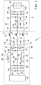
- FIG. 1 A schematic view of an electric vehicle charging arrangement 1 according to an embodiment of the invention is shown in figure 1 .
- the electric vehicle charging arrangement 1 is provided with an electric vehicle supply equipment 2, EVSE, for supplying electric energy to an electric vehicle 3 for charging the electric vehicle 3, in particular the battery 40 thereof.
- EVSE electric vehicle supply equipment
- the EVSE 2 comprises a power module 10 that is configured for receiving electric energy from a not shown power source, wherein the power source may be an alternating current (AC) power source, such as the electricity grid, or a direct current (DC) power source, such as a power cabinet.
- the power module 10 is configured for converting the received electric energy into a direct current (DC) appropriate for charging the electric vehicle 3.
- the EVSE is provided with a first DC bus 11 and a not shown plug, located at the outside of the EVSE 2, to be inserted into a not shown socket of the electric vehicle 3, as schematically indicated by the dotted line.
- the plug defines the output of the EVSE 2, wherein the first DC bus 11 extends between the output and the power module 10 and/or is part of the output of the EVSE 2.
- the socket is at least part of an input of the electric vehicle 3.
- FIG. 1 seems to show that the power module 10 and the battery 40 of the electric vehicle 3 are connected directly to each other, it is noted that the described plug and socket are provided between the EVSE 2 and the electric vehicle 3. Thus, a plug-and-socket connection is present between the EVSE 2 and the electric vehicle 3 in order to connect them releasable to each other.
- the first DC bus 11 comprises a first DC+ line 12, a first DC-line 13 and a first protective earth (PE) line 14.
- the first DC+ line 12 and the first DC- line 13 extend from the power module 10 to the electric vehicle 3, and the PE line 14 extends from an electric earth 15 within the EVSE 2 to the electric vehicle 3.
- the PE line 14 is provided for directing a fault current safely into the earth and away from a user of the electric vehicle charging arrangement 1 in order to prevent the user from getting an electric shock from the electric vehicle charging arrangement 1.
- each of the first DC+ line 12, the first DC- line 13 and the first PE line 14 has a line resistance 16 and a line inductance 17 due to the properties of the material used for manufacturing the first DC+ line 12, the first DC- line 13 and the first PE line 14.
- the first DC+ line 12 has a first DC+ contactor 18 and the first DC- line 13 has a first DC- contactor 19 for selectively connecting the power module 10 of the EVSE 2 to the battery 40 of the electric vehicle 3.
- a first X capacitor 20 is provided between the first DC+ line 12 and the first DC- line 13
- a first Y capacitor 21 is provided between the first DC+ line 12 and the first PE line 14
- a second Y capacitor 22 is provided between the first DC- line 13 and the first PE line 14.
- a first isolating resistor 23 is provided between the first DC+ line 12 and the PE line 14
- a second isolating resistor 24 is provided between the first DC- line 13 and the PE line 14, both downstream of the power module 10 and upstream of the first DC+ contactor 18 and the first DC- contactor 19.
- a second X capacitor 25 is provided between the first DC+ line 12 and the first DC- line 13.
- the second X capacitor 25 is configured to function as a filter for the first DC between the first DC+ line 12 and the first DC- line 13.
- An isolation monitoring device, IMD, 26, having a galvanometer 27 and an isolation monitoring resistor 28, is provided between the first DC+ line 12 and the PE line 14, and between the first DC- line 13 and the PE line 14.
- Each IMD 26 is configured for monitoring at least the EVSE 2 between the first DC+ line 12 and the first PE line 14, or between the first DC- line 13 and the first PE line 14, respectively, and is configured to give an alert and/or to disconnect the power module 10 from the electric vehicle 3 when a resistance between the first DC+ line 12 and the first PE line 14, or between the first DC-line 13 and the first PE line 14, respectively, drops below a predetermined threshold.
- the electric vehicle 3 is provided with a second DC bus 41, having a second DC+ line 42, a second DC- line 43 and a second PE line 44, which is configured to be connected to the first DC bus 11 by means of the plug-and-socket connection.
- Each of the second DC+ line 42 and the second DC- line 43 is provided with a second DC+ contactor 45 and a second DC- contactor 46, respectively, for selectively connecting the battery 40 to the power module 10.
- Upstream of the second contactors 45, 46, a first measure resistor 47 and a second measure resistor 48 are arranged in series between the second DC+ line 42 and the second DC- line 43.
- a third X capacitor 49 is arranged between the second DC+ line 42 and the second DC-line 43
- a third Y capacitor 50 is arranged between the second DC+ line 42 and the second PE line 44
- a fourth Y capacitor 51 is arranged between the second DC- line and the second PE line 44.
- a third isolating resistor 52 is arranged between the second DC+ line 42 and the second PE line 44
- a fourth isolating resistor 53 is arranged between the second DC- line and the second PE line 44.
- the second DC bus 41 and the first DC bus 11 are connected to each other by means of the described plug-and-socket connection, while at least the second contactors 45, 46 are open such that the power module 10 is not directly connected to the battery 40 of the electric vehicle 3 upon plugging the plug into the socket. This is done to prevent high inrush current from occurring.
- the first contactors 18, 19 are also open.
- the output of the EVSE 2 is charged to a voltage near to the battery voltage of the battery 40, with a ⁇ 20V tolerance, and charging the internal capacitors, such as the first and second X capacitors 20, 25 and the first and second Y capacitors 21, 22, at the output to prevent or to limit a high inrush current when the battery 40 is connected to the DC bus 11 and/or to the power module 10.
- the EVSE 2 is provided with a first precharge circuit 60 parallel to the first DC+ contactor 18, and with a second precharge circuit 61 parallel to the first DC- contactor 19.
- the first and second precharge circuits 60, 61 are arranged parallel to the respective first contactor 18, 19, such that the first and second precharge circuits 60, 61 are allowed to precharge capacitances downstream of the first contactors 18, 19 while the first contactors 18, 19 are open.
- each of the first precharge circuit 60 and the second precharge circuit 61 is provided with a precharge resistor 62 and a precharge relay 63, which are arranged in series.
- the precharge relay 63 is configured for moving between an open position, in which the respective precharge circuit 60, 61 is not enabled to precharge, and a closed position, in which the respective precharge circuit 60, 61 is enabled to precharge.
- the precharge resistor 62 as shown in figure 1 is a single precharge resistor 62.
- the precharge resistor 62 may be replaced by a precharge resistor matrix 70 as shown in figure 2 .
- the precharge resistor matrix 70 comprises a plurality of matrix resistors 71-79.
- the matrix resistors 71-79 are arranged in such manner that a number of matrix resistors 71-73, 74-76, 77-79 are in series with each other, and that a number of matrix resistors 71-73, 74-76, 77-79 are parallel to each other.
- the precharge matrix 70 has as an advantage that if one of the matrix resistors 71-79, for example matrix resistor 74 is shorted or has another failure, the other remaining matrix resistors 71-73, 75-79 are available to take over the function of the matrix resistor 74 that is shorted or has another failure. It, thereby, is prevented that a huge inrush currents occurs in case of a precharging resistor that is shorted or has another failure.
Abstract
Description
- The invention relates to an electric vehicle charging arrangement for charging an electric vehicle, comprising an electric vehicle supply equipment. Furthermore, the invention relates to a method for charging an electric vehicle by an electric vehicle charging arrangement.
- Such an electric vehicle charging arrangement is known, wherein the known electric vehicle charging arrangement comprises a power module configured for providing electrical energy to charge the electric vehicle and an output configured for connecting the power module to the electric vehicle for charging the electric vehicle. A direct current (DC) bus with a DC+ line and a DC-line is provided between and connected to the power module and the output and configured for transporting electric energy from the power module to the output. Each of the DC+ line and the DC- line is provided with a contactor configured for selectively allowing a current flow from the power module to the output. Furthermore, a precharge circuit, having a precharge resistor, is provided in parallel to the contactor of one of the DC+ line or the DC- line.
- Before starting the charging of an electric vehicle after connecting the electric vehicle to the electric vehicle supply equipment, precharging of the output of the electric vehicle supply equipment has to be performed. During precharging, the vehicle battery of the electric vehicle is not connected to the DC bus yet, because the contactors of the DC+ line and the DC- line are in the open position. Precharging involves charging the voltage at the output near to the battery voltage of the vehicle battery, with a ±20V tolerance, and charging the internal capacitors at the output to prevent or to limit a high inrush current when the vehicle battery is connected to the DC bus. If the high inrush current is not prevented or limited, the contactors of the DC+ line and the DC- line may get damaged by the high inrush current.
- In the current charging standards, only the precharge between the DC+ line and the DC- line is considered. However, there are actually three connections involved between the electric vehicle supply equipment and the electric vehicle to be charged, namely the DC+ line, the DC- line, and the PE (Protective Earth) line. In the known electric vehicle supply equipment, the precharge circuit is only used on the DC+ line or on the DC- line. A disadvantage of the known electric vehicle supply equipment is that a high inrush current has been seen on the line without precharge circuit due to the Y capacitance and unbalance between the electric vehicle supply equipment and the electric vehicle.
- It is an object of the present invention to provide an electric vehicle charging arrangement or a method for charging an electric vehicle, in which high inrush currents are prevented from occurring.
- According to a first aspect, the invention provides an electric vehicle charging arrangement for charging an electric vehicle, comprising an electric vehicle supply equipment (EVSE), wherein the EVSE comprises:
- a power module configured for providing electrical energy to charge the electric vehicle,
- an output configured for connecting the power module to the electric vehicle for charging the electric vehicle, and
- a direct current (DC) bus having a DC+ line and a DC- line and provided between and connected to the power module and the output and configured for transporting electric energy from the power module to the output,
- wherein each of the DC+ line and the DC- line is provided with a contactor configured for selectively allowing a current flow from the power module to the output, and
- wherein a first precharge circuit is provided in parallel to the contactor of the DC+ line, and a second precharge circuit is provided in parallel to the contactor of the DC- line.
- During use of the electric vehicle charging arrangement according to the invention, precharging of the output of the EVSE is performed on each of the DC+ line and the DC- line of the DC bus, in particular simultaneously. Since precharging is performed on both of the DC+ line and the DC- line of the DC bus, a high inrush current occurring at one of the DC+ line and the DC- line can be limited on both of the DC+ line and the DC- line, or the risk of a high inrush current occurring at one of the DC+ line and the DC- line can be eliminated in the ideal case.
- In the context of the present patent application, the output may be understood to comprise a charging cable and a charging connector, a pantograph and/or an automatic connection system for connecting an electric vehicle to the EVSE.
- Furthermore, in the context of the present application, an electric vehicle supply equipment (EVSE) may be referred to as electric vehicle charger, electric vehicle, EV, charging station, electric recharging point, charging point, charge point, charge post or electronic charging station (ECS). The electric vehicle charger is an element in an infrastructure that supplies electric energy for recharging of electric vehicles, including electric cars, neighborhood electric vehicles, electric busses and plug-in hybrids, for example via a charging cable and a charging connector, via a pantograph and/or via an automatic connection system to the EV. Electric vehicle chargers usually comply with standards for electric vehicle fast charging, such as the so-called Combined Charging System (CCS) protocol according to IEC 61851-23 and SAE J1772 standard for charging electric vehicles both in the US and in the European Union, EU. The Combined Charging System (CCS) protocol is a fast charging method for charging electric vehicles delivering high-voltage direct current via a charging connector derived from SAE J1772 standard (IEC Type 1) or IEC Type 2 connector. The proposed electric vehicle charging arrangement may be advantageously used with even higher charging currents such as or more than 500A, 600A or 3000A, voltages such as or higher 1000V, 1500V or 3000V and/or in combination with newer standards not yet defined requiring higher currents.
- In an embodiment, each of the first precharge circuit and the second precharge circuit comprises a precharge resistor. Preferably, each of the first precharge circuit and the second precharge circuit comprises a precharge relay that is arranged downstream of and in series with the precharge resistor. By arranging the precharge resistor and the precharge relay in series and in parallel to the contactor of the DC+ line and the DC- line, respectively, the precharge resistor may be switched to during precharging, when the respective contactor is open and the respective precharge relay is closed, such that no current may flow through the respective contactor and current may flow through the precharge resistor. When precharging is completed, the respective precharge relay is opened and the associated contactor is closed, such that current may flow through the closed contactor for charging the electric vehicle.
- In an embodiment, at least one of the first precharge circuit and the second precharge circuit comprises a precharge resistor matrix with a plurality of matrix resistors. In an embodiment, a number of matrix resistors are arranged in series with each other. Preferably, a number of matrix resistors are arranged in parallel to each other. It may be disadvantageous when the precharge circuit has only a single precharge resistor, since once the precharge resistor is shorted or has another failure, there will be a huge inrush current, for example, when the contactor is closed. The precharge resistor matrix has as an advantage that a huge inrush current may still be limited or even may still be prevented from occurring by one or more of the matrix resistors, when one of the matrix resistors is shorted or has another failure.
- Preferably, each of the first precharge circuit and the second precharge circuit comprises a precharge relay that is arranged downstream of and in series with the precharge resistor matrix.
- In an embodiment, the EVSE comprises one or more X capacitors and/or one or more Y capacitors. By providing one or more X capacitors between the DC+ line and the DC-line, in particular downstream of the first and second precharge circuits, the direct current (DC) transported by the DC bus may be filtered by means of such one or more X capacitors.
- In an embodiment, the EVSE comprises an isolation monitoring device, and/or one or more isolating resistors. During use, it may occur that the resistance, for example, between the DC+ line and earth suddenly drops below a predetermined value. Such a drop of resistance may result in an increased current on the DC bus, which increased current may be detrimental, for example, for the contactors of the DC+ line and the DC- line. The isolation monitoring device is intended to give an alert and/or to disconnect the power module, for example by opening the contactors of the DC+ line and the DC- line, in case of a sudden drop of the resistance, for example between the DC+ line and earth. This is advantageous, as it may prevent a too high current from occurring on the DC bus.
- In an embodiment, the DC bus is a first DC bus, the DC+ line is a first DC+ line and the DC- line is a first DC- line, wherein the electric vehicle charging arrangement comprises an electric vehicle having a battery, an input configured for being connected or connected to the output of the EVSE, and a second DC bus between the input and the battery, wherein the second DC bus has a second DC+ line and a second DC- line, each provided with a second contactor. When connecting the electric vehicle to the EVSE, the second contactors on the second DC+ line and the second DC- line are open such that the battery of the electric vehicle is not directly connected to the first DC bus and the power module of the EVSE upon connection of the electric vehicle to the EVSE. This is advantageous, as it thereby is prevented that the battery of the electric vehicle is connected to the power module via the precharge circuit.
- In an embodiment, the DC bus comprises a protective earth line.
- According to a second aspect, the invention provides a method for charging an electric vehicle by means of an electric vehicle supply equipment (EVSE) comprising
- a power module configured for providing electrical energy to charge the electric vehicle,
- an output configured for connecting the power module to the electric vehicle for charging the electric vehicle, and
- a direct current (DC) bus having a DC+ line and a DC- line and provided between and connected to the power module and the output and configured for transporting electric energy from the power module to the output,
- wherein each of the DC+ line and the DC- line is provided with a contactor configured for selectively allowing a current flow from the power module to the output, and
- wherein a first precharge circuit is provided in parallel to the contactor of the DC+ line, and a second precharge circuit is provided in parallel to the contactor of the DC- line,
- wherein the method comprises the steps of:
- connecting the electric vehicle to the EVSE, in particular the output thereof, while the contactor of each of the DC+ line and the DC- line is open;
- precharging the output of the EVSE on the DC+ line and the DC- line; and
- when precharging is complete, closing the contactor of each of the DC+ line and the DC- line to start charging the electric vehicle.
- The method according to the invention has at least the same technical advantage as described in relation to the electric vehicle charging arrangement according to the first aspect of the invention.
- In an embodiment, the DC bus is a first DC bus, the DC+ line is a first DC+ line and the DC- line is a first DC- line, wherein the electric vehicle charging arrangement comprises an electric vehicle having a battery, an input configured for being connected or connected to the output of the EVSE, and a second DC bus between the input and the battery, wherein the second DC bus has a second DC+ line and a second DC- line, each provided with a second contactor,
wherein the step of connecting the electric vehicle to the EVSE comprises connecting the electric vehicle to the EVSE, while the second contactor of each of the second DC+ line and the second DC- line is open. - In an embodiment, the step of, when precharging is complete, closing the contactor of each of the DC+ line and the DC- line to start charging the electric vehicle comprises closing the second contactor of each of the second DC+ line and the second DC- line.
- The various aspects and features described and shown in the specification can be applied, individually, wherever possible. These individual aspects, in particular the aspects and features described in the attached dependent claims, can be made subject of divisional patent applications.
- The invention will be elucidated on the basis of an exemplary embodiment shown in the attached drawings, in which:
-
Figure 1 shows a schematic view of an electric vehicle charging arrangement having an electric vehicle supply equipment with a precharge circuit having a precharge resistor according to an embodiment of the invention; and -
Figure 2 shows a schematic view of an alternative for the precharge resistor offigure 1 . - A schematic view of an electric
vehicle charging arrangement 1 according to an embodiment of the invention is shown infigure 1 . The electricvehicle charging arrangement 1 is provided with an electric vehicle supply equipment 2, EVSE, for supplying electric energy to anelectric vehicle 3 for charging theelectric vehicle 3, in particular thebattery 40 thereof. - As shown in
figure 1 , the EVSE 2 comprises apower module 10 that is configured for receiving electric energy from a not shown power source, wherein the power source may be an alternating current (AC) power source, such as the electricity grid, or a direct current (DC) power source, such as a power cabinet. Thepower module 10 is configured for converting the received electric energy into a direct current (DC) appropriate for charging theelectric vehicle 3. In order to establish an electric connected between thepower module 10 and theelectric vehicle 3, the EVSE is provided with afirst DC bus 11 and a not shown plug, located at the outside of the EVSE 2, to be inserted into a not shown socket of theelectric vehicle 3, as schematically indicated by the dotted line. The plug defines the output of the EVSE 2, wherein thefirst DC bus 11 extends between the output and thepower module 10 and/or is part of the output of the EVSE 2. The socket is at least part of an input of theelectric vehicle 3. - Although
figure 1 seems to show that thepower module 10 and thebattery 40 of theelectric vehicle 3 are connected directly to each other, it is noted that the described plug and socket are provided between the EVSE 2 and theelectric vehicle 3. Thus, a plug-and-socket connection is present between the EVSE 2 and theelectric vehicle 3 in order to connect them releasable to each other. - The
first DC bus 11 comprises afirst DC+ line 12, a first DC-line 13 and a first protective earth (PE)line 14. Thefirst DC+ line 12 and the first DC-line 13 extend from thepower module 10 to theelectric vehicle 3, and thePE line 14 extends from anelectric earth 15 within the EVSE 2 to theelectric vehicle 3. ThePE line 14 is provided for directing a fault current safely into the earth and away from a user of the electricvehicle charging arrangement 1 in order to prevent the user from getting an electric shock from the electricvehicle charging arrangement 1. As schematically indicated withinfigure 1 , each of thefirst DC+ line 12, the first DC-line 13 and thefirst PE line 14 has aline resistance 16 and aline inductance 17 due to the properties of the material used for manufacturing thefirst DC+ line 12, the first DC-line 13 and thefirst PE line 14. - As shown in
figure 1 , thefirst DC+ line 12 has afirst DC+ contactor 18 and the first DC-line 13 has a first DC-contactor 19 for selectively connecting thepower module 10 of the EVSE 2 to thebattery 40 of theelectric vehicle 3. Downstream of thepower module 10 and upstream of thefirst DC+ contactor 18 and the first DC-contactor 19, afirst X capacitor 20 is provided between thefirst DC+ line 12 and the first DC-line 13, afirst Y capacitor 21 is provided between thefirst DC+ line 12 and thefirst PE line 14, and asecond Y capacitor 22 is provided between the first DC-line 13 and thefirst PE line 14. Additionally, a first isolatingresistor 23 is provided between thefirst DC+ line 12 and thePE line 14, and a second isolatingresistor 24 is provided between the first DC-line 13 and thePE line 14, both downstream of thepower module 10 and upstream of thefirst DC+ contactor 18 and the first DC-contactor 19. - Downstream of the
first DC+ contactor 18 and the first DC-contactor 19, asecond X capacitor 25 is provided between thefirst DC+ line 12 and the first DC-line 13. Thesecond X capacitor 25 is configured to function as a filter for the first DC between thefirst DC+ line 12 and the first DC-line 13. An isolation monitoring device, IMD, 26, having agalvanometer 27 and anisolation monitoring resistor 28, is provided between thefirst DC+ line 12 and thePE line 14, and between the first DC-line 13 and thePE line 14. EachIMD 26 is configured for monitoring at least the EVSE 2 between thefirst DC+ line 12 and thefirst PE line 14, or between the first DC-line 13 and thefirst PE line 14, respectively, and is configured to give an alert and/or to disconnect thepower module 10 from theelectric vehicle 3 when a resistance between thefirst DC+ line 12 and thefirst PE line 14, or between the first DC-line 13 and thefirst PE line 14, respectively, drops below a predetermined threshold. - As shown in
figure 1 , theelectric vehicle 3 is provided with asecond DC bus 41, having asecond DC+ line 42, a second DC-line 43 and asecond PE line 44, which is configured to be connected to thefirst DC bus 11 by means of the plug-and-socket connection. Each of thesecond DC+ line 42 and the second DC-line 43 is provided with asecond DC+ contactor 45 and a second DC-contactor 46, respectively, for selectively connecting thebattery 40 to thepower module 10. Upstream of thesecond contactors first measure resistor 47 and asecond measure resistor 48 are arranged in series between thesecond DC+ line 42 and the second DC-line 43. Downstream of thesecond contactors third X capacitor 49 is arranged between thesecond DC+ line 42 and the second DC-line 43, athird Y capacitor 50 is arranged between thesecond DC+ line 42 and thesecond PE line 44, and afourth Y capacitor 51 is arranged between the second DC- line and thesecond PE line 44. Furthermore, a third isolatingresistor 52 is arranged between thesecond DC+ line 42 and thesecond PE line 44, and a fourth isolatingresistor 53 is arranged between the second DC- line and thesecond PE line 44. - When the
electric vehicle 3 needs to be charged, thesecond DC bus 41 and thefirst DC bus 11 are connected to each other by means of the described plug-and-socket connection, while at least thesecond contactors power module 10 is not directly connected to thebattery 40 of theelectric vehicle 3 upon plugging the plug into the socket. This is done to prevent high inrush current from occurring. Preferably, thefirst contactors first contactors second contactors battery 40, with a ±20V tolerance, and charging the internal capacitors, such as the first andsecond X capacitors second Y capacitors battery 40 is connected to theDC bus 11 and/or to thepower module 10. - In order to perform precharging, the EVSE 2 is provided with a first
precharge circuit 60 parallel to thefirst DC+ contactor 18, and with a secondprecharge circuit 61 parallel to the first DC-contactor 19. The first and secondprecharge circuits first contactor precharge circuits first contactors first contactors precharge circuit 60 on thefirst DC+ line 12, and the secondprecharge circuit 61 on the first DC-line 13, high inrush currents can be limited or prevented on both of thefirst DC+ line 12 and the first DC-line 13. - As shown in
figure 1 , each of the firstprecharge circuit 60 and the secondprecharge circuit 61 is provided with aprecharge resistor 62 and aprecharge relay 63, which are arranged in series. Theprecharge relay 63 is configured for moving between an open position, in which the respectiveprecharge circuit precharge circuit - The
precharge resistor 62 as shown infigure 1 is a singleprecharge resistor 62. Alternatively, theprecharge resistor 62 may be replaced by aprecharge resistor matrix 70 as shown infigure 2 . Theprecharge resistor matrix 70 comprises a plurality of matrix resistors 71-79. The matrix resistors 71-79 are arranged in such manner that a number of matrix resistors 71-73, 74-76, 77-79 are in series with each other, and that a number of matrix resistors 71-73, 74-76, 77-79 are parallel to each other. Theprecharge matrix 70 has as an advantage that if one of the matrix resistors 71-79, forexample matrix resistor 74 is shorted or has another failure, the other remaining matrix resistors 71-73, 75-79 are available to take over the function of thematrix resistor 74 that is shorted or has another failure. It, thereby, is prevented that a huge inrush currents occurs in case of a precharging resistor that is shorted or has another failure. - It is to be understood that the above description is included to illustrate the operation of the preferred embodiments and is not meant to limit the scope of the invention. From the above discussion, many variations will be apparent to one skilled in the art that would yet be encompassed by the scope of the present invention.
-
- 1
- electric vehicle charging arrangement
- 2
- electric vehicle supply equipment
- 3
- electric vehicle
- 10
- power module
- 11
- first DC bus
- 12
- first DC+ line
- 13
- first DC- line
- 14
- first PE line
- 15
- electric earth
- 16
- line resistance
- 17
- line inductance
- 18
- first DC+ contactor
- 19
- first DC- contactor
- 20
- first X capacitor
- 21
- first Y capacitor
- 22
- second Y capacitor
- 23
- first isolating resistor
- 24
- second isolating resistor
- 25
- second X capacitor
- 26
- isolation monitoring device
- 27
- galvanometer
- 28
- isolation monitoring resistor
- 40
- battery
- 41
- second DC bus
- 42
- second DC+ line
- 43
- second DC- line
- 44
- second PE line
- 45
- second DC+ contactor
- 46
- second DC- contactor
- 47
- first measure resistor
- 48
- second measure resistor
- 49
- third X capacitor
- 50
- third Y capacitor
- 51
- fourth Y capacitor
- 52
- third isolating resistor
- 53
- fourth isolating resistor
- 60
- first precharge circuit
- 61
- second precharge circuit
- 62
- precharge resistor
- 63
- precharge relay
- 70
- precharge resistor matrix
- 71-79
- matrix resistors
Claims (14)
- Electric vehicle charging arrangement (1) for charging an electric vehicle (3), comprising an electric vehicle supply equipment (EVSE) (2), wherein the EVSE comprises (2):a power module (10) configured for providing electrical energy to charge the electric vehicle,an output configured for connecting the power module (10) to the electric vehicle (3) for charging the electric vehicle (3), anda direct current (DC) (11) bus having a DC+ line (12) and a DC- line (13) and provided between and connected to the power module (10) and the output and configured for transporting electric energy from the power module (10) to the output,wherein each of the DC+ line (12) and the DC-line (13) is provided with a contactor (18, 19) configured for selectively allowing a current flow from the power module (10) to the output, andwherein a first precharge circuit (60) is provided in parallel to the contactor (18) of the DC+ line (12), and a second precharge circuit (61) is provided in parallel to the contactor (19) of the DC- line (13).
- Electric vehicle charging arrangement (1) according to claim 1, wherein each of the first precharge circuit (60) and the second precharge circuit (61) comprises a precharge resistor (62).
- Electric vehicle charging arrangement (1) according to claim 2, wherein each of the first precharge circuit (60) and the second precharge circuit (61) comprises a precharge relay (63) that is arranged downstream of and in series with the precharge resistor (62) .
- Electric vehicle charging arrangement (1) according to claim 1, wherein at least one of the first precharge circuit (60) and the second precharge circuit (61) comprises a precharge resistor matrix (70) with a plurality of matrix resistors (71-79).
- Electric vehicle charging arrangement (1) according to claim 4, wherein a number of matrix resistors (71-73; 74-76; 77-79) are arranged in series with each other.
- Electric vehicle charging arrangement (1) according to claim 4 or 5, wherein a number of matrix resistors (71-73; 74-76; 77-79) are arranged in parallel to each other.
- Electric vehicle charging arrangement (1) according to any one of claims 4-6, wherein each of the first precharge circuit (60) and the second precharge circuit (61) comprises a precharge relay (63) that is arranged downstream of and in series with the precharge resistor matrix (70).
- Electric vehicle charging arrangement (1) according to any one of the preceding claims, wherein the EVSE (2) comprises one or more X capacitors (20, 25) and/or one or more Y capacitors (21, 22).
- Electric vehicle charging arrangement (1) according to any one of the preceding claims, wherein the EVSE (2) comprises an isolation monitoring device (26), and/or one or more isolating resistors (23, 24).
- Electric vehicle charging arrangement (1) according to any one of the preceding claims, wherein the DC bus (11) is a first DC bus (11), the DC+ line (12) is a first DC+ line (12) and the DC- line (13) is a first DC-line (13), wherein the electric vehicle charging arrangement (1) comprises an electric vehicle (3) having a battery (40), an input configured for being connected or connected to the output of the EVSE (2), and a second DC bus (41) between the input and the battery (40), wherein the second DC bus (41) has a second DC+ line (42) and a second DC- line (43), each provided with a second contactor (45, 46) .
- Electric vehicle charging arrangement (1) according to any one of the preceding claims, wherein the DC bus (11) comprises a protective earth (PE) line (14).
- Method for charging an electric vehicle (3) by means of an electric vehicle supply equipment (EVSE) (2) comprisinga power module (10) configured for providing electrical energy to charge the electric vehicle,an output configured for connecting the power module (10) to the electric vehicle (3) for charging the electric vehicle (3), anda direct current (DC) (11) bus having a DC+ line (12) and a DC- line (13) and provided between and connected to the power module (10) and the output and configured for transporting electric energy from the power module (10) to the output,wherein each of the DC+ line (12) and the DC-line (13) is provided with a contactor (18, 19) configured for selectively allowing a current flow from the power module (10) to the output, andwherein a first precharge circuit (60) is provided in parallel to the contactor (18) of the DC+ line (12), and a second precharge circuit (61) is provided in parallel to the contactor (19) of the DC- line (13),wherein the method comprises the steps of:- connecting the electric vehicle (3) to the EVSE (2), in particular the output thereof, while the contactor (18, 19) of each of the DC+ line (12) and the DC-line (13) is open;- precharging the output of the EVSE (2) on the DC+ line (12) and the DC- line (13); and- when precharging is complete, closing the contactor (18, 19) of each of the DC+ line (12) and the DC-line (13) to start charging the electric vehicle (3).
- Method according to claim 12, wherein the DC bus (11) is a first DC bus (11), the DC+ line (12) is a first DC+ line (12) and the DC- line (13) is a first DC-line (13), wherein the electric vehicle charging arrangement (1) comprises an electric vehicle (3) having a battery (40), an input configured for being connected or connected to the output of the EVSE (2), and a second DC bus (41) between the input and the battery (40), wherein the second DC bus (41) has a second DC+ line (42) and a second DC- line (43), each provided with a second contactor (45, 46),
wherein the step of connecting the electric vehicle (3) to the EVSE (2) comprises connecting the electric vehicle (3) to the EVSE (2), while the second contactor of each of the second DC+ line (42) and the second DC- line (43) is open. - Method according to claim 13, wherein the step of, when precharging is complete, closing the contactor (18, 19) of each of the DC+ line (12) and the DC-line (13) to start charging the electric vehicle (3) comprises closing the second contactor of each of the second DC+ line (42) and the second DC- line (43).
Priority Applications (3)
| Application Number | Priority Date | Filing Date | Title |
|---|---|---|---|
| EP21193847.7A EP4140800A1 (en) | 2021-08-30 | 2021-08-30 | Electric vehicle charging arrangement with pre-arging and method for charging an electric vehicle |
| CN202211050699.3A CN115723595A (en) | 2021-08-30 | 2022-08-29 | Electric vehicle charging device and method for charging electric vehicle |
| US17/898,673 US20230061714A1 (en) | 2021-08-30 | 2022-08-30 | Electric vehicle charging arrangement and method for charging an electric vehicle |
Applications Claiming Priority (1)
| Application Number | Priority Date | Filing Date | Title |
|---|---|---|---|
| EP21193847.7A EP4140800A1 (en) | 2021-08-30 | 2021-08-30 | Electric vehicle charging arrangement with pre-arging and method for charging an electric vehicle |
Publications (1)
| Publication Number | Publication Date |
|---|---|
| EP4140800A1 true EP4140800A1 (en) | 2023-03-01 |
Family
ID=77543423
Family Applications (1)
| Application Number | Title | Priority Date | Filing Date |
|---|---|---|---|
| EP21193847.7A Pending EP4140800A1 (en) | 2021-08-30 | 2021-08-30 | Electric vehicle charging arrangement with pre-arging and method for charging an electric vehicle |
Country Status (3)
| Country | Link |
|---|---|
| US (1) | US20230061714A1 (en) |
| EP (1) | EP4140800A1 (en) |
| CN (1) | CN115723595A (en) |
Citations (5)
| Publication number | Priority date | Publication date | Assignee | Title |
|---|---|---|---|---|
| US20140021916A1 (en) * | 2012-07-23 | 2014-01-23 | Ford Global Technologies, Llc | Low Cost Charger Circuit with Precharge |
| US20150274024A1 (en) * | 2012-10-30 | 2015-10-01 | Valeo Systemes De Controle Moteur | Charge transfer method and related electric device |
| US20170166075A1 (en) * | 2015-12-15 | 2017-06-15 | Faraday&Future Inc. | Systems and methods for connecting battery strings to a dc bus |
| EP3564059A1 (en) * | 2018-04-30 | 2019-11-06 | ABB Schweiz AG | Pe loss detection |
| US20200406768A1 (en) * | 2018-03-08 | 2020-12-31 | Vitesco Technologies GmbH | Alternating-current charging device for a motor vehicle, and method for operating an alternating-current charging device for a motor vehicle |
-
2021
- 2021-08-30 EP EP21193847.7A patent/EP4140800A1/en active Pending
-
2022
- 2022-08-29 CN CN202211050699.3A patent/CN115723595A/en active Pending
- 2022-08-30 US US17/898,673 patent/US20230061714A1/en active Pending
Patent Citations (5)
| Publication number | Priority date | Publication date | Assignee | Title |
|---|---|---|---|---|
| US20140021916A1 (en) * | 2012-07-23 | 2014-01-23 | Ford Global Technologies, Llc | Low Cost Charger Circuit with Precharge |
| US20150274024A1 (en) * | 2012-10-30 | 2015-10-01 | Valeo Systemes De Controle Moteur | Charge transfer method and related electric device |
| US20170166075A1 (en) * | 2015-12-15 | 2017-06-15 | Faraday&Future Inc. | Systems and methods for connecting battery strings to a dc bus |
| US20200406768A1 (en) * | 2018-03-08 | 2020-12-31 | Vitesco Technologies GmbH | Alternating-current charging device for a motor vehicle, and method for operating an alternating-current charging device for a motor vehicle |
| EP3564059A1 (en) * | 2018-04-30 | 2019-11-06 | ABB Schweiz AG | Pe loss detection |
Also Published As
| Publication number | Publication date |
|---|---|
| US20230061714A1 (en) | 2023-03-02 |
| CN115723595A (en) | 2023-03-03 |
Similar Documents
| Publication | Publication Date | Title |
|---|---|---|
| CN111284361B (en) | Power supply system | |
| CN103119822B (en) | Electrical storage system and method for controlling electrical storage system | |
| CN110521080B (en) | Circuit arrangement for an electrical energy storage system and charging method | |
| CN102474172B (en) | Method for discharging intermediate circuit capacitor of intermediate voltage circuit converter | |
| CN103858297B (en) | Electric vehicles charge and discharge device | |
| US10513185B2 (en) | Electrified vehicle ground fault monitoring system | |
| CN110091733B (en) | Charging device and vehicle | |
| KR20180066611A (en) | Apparatus for charge controlling of electric vehicle | |
| US9401597B2 (en) | Method and device for discharging an intermediate circuit of a power supply network | |
| JP6178328B2 (en) | DC voltage source including an electrochemical cell | |
| CN103072490A (en) | Automotive power source apparatus and vehicle equipped with the power source apparatus | |
| CN104221244A (en) | Method for balancing the charge and discharge level of a battery by switching its blocks of cells | |
| JP2013076602A (en) | Power storage system | |
| KR102654831B1 (en) | Apparatus and method for controlling charging a high voltage power grid structure of a vehicle | |
| US11351876B2 (en) | Vehicle power supply system | |
| DE102010063126A1 (en) | Device for charging high volt battery of motor vehicle e.g. electric vehicle, has monitoring device monitoring hazardous condition of device, and separating and/or discharge device transmitting control signal based on hazardous condition | |
| EP3800083A1 (en) | Power-supply and recharge groups of an electric vehicle and methods thereof | |
| EP4140800A1 (en) | Electric vehicle charging arrangement with pre-arging and method for charging an electric vehicle | |
| CN115003546A (en) | Electric vehicle charging apparatus and corresponding method | |
| CN105846519A (en) | Method and apparatus for electrically charging a high-voltage battery from an AC power supply system | |
| CN110098424A (en) | A kind of fuel cell high pressure integrating device, system and automobile | |
| EP4122750A1 (en) | Electric vehicle charging arrangement and respective method | |
| CN115803218A (en) | Method for connecting one or more battery cells to an electrical system | |
| KR20210115479A (en) | Electric vehicle charging controller and apparatus for charging electric vehicle comprising the same | |
| CN110816316B (en) | Method for testing a charging process |
Legal Events
| Date | Code | Title | Description |
|---|---|---|---|
| PUAI | Public reference made under article 153(3) epc to a published international application that has entered the european phase |
Free format text: ORIGINAL CODE: 0009012 |
|
| STAA | Information on the status of an ep patent application or granted ep patent |
Free format text: STATUS: THE APPLICATION HAS BEEN PUBLISHED |
|
| AK | Designated contracting states |
Kind code of ref document: A1 Designated state(s): AL AT BE BG CH CY CZ DE DK EE ES FI FR GB GR HR HU IE IS IT LI LT LU LV MC MK MT NL NO PL PT RO RS SE SI SK SM TR |
|
| STAA | Information on the status of an ep patent application or granted ep patent |
Free format text: STATUS: REQUEST FOR EXAMINATION WAS MADE |
|
| 17P | Request for examination filed |
Effective date: 20230901 |
|
| RBV | Designated contracting states (corrected) |
Designated state(s): AL AT BE BG CH CY CZ DE DK EE ES FI FR GB GR HR HU IE IS IT LI LT LU LV MC MK MT NL NO PL PT RO RS SE SI SK SM TR |