EP4140790A1 - Motor vehicle battery support - Google Patents
Motor vehicle battery support Download PDFInfo
- Publication number
- EP4140790A1 EP4140790A1 EP21194163.8A EP21194163A EP4140790A1 EP 4140790 A1 EP4140790 A1 EP 4140790A1 EP 21194163 A EP21194163 A EP 21194163A EP 4140790 A1 EP4140790 A1 EP 4140790A1
- Authority
- EP
- European Patent Office
- Prior art keywords
- flange
- motor vehicle
- battery
- battery support
- vehicle according
- Prior art date
- Legal status (The legal status is an assumption and is not a legal conclusion. Google has not performed a legal analysis and makes no representation as to the accuracy of the status listed.)
- Granted
Links
Images

Classifications
-
- B—PERFORMING OPERATIONS; TRANSPORTING
- B60—VEHICLES IN GENERAL
- B60K—ARRANGEMENT OR MOUNTING OF PROPULSION UNITS OR OF TRANSMISSIONS IN VEHICLES; ARRANGEMENT OR MOUNTING OF PLURAL DIVERSE PRIME-MOVERS IN VEHICLES; AUXILIARY DRIVES FOR VEHICLES; INSTRUMENTATION OR DASHBOARDS FOR VEHICLES; ARRANGEMENTS IN CONNECTION WITH COOLING, AIR INTAKE, GAS EXHAUST OR FUEL SUPPLY OF PROPULSION UNITS IN VEHICLES
- B60K1/00—Arrangement or mounting of electrical propulsion units
- B60K1/04—Arrangement or mounting of electrical propulsion units of the electric storage means for propulsion
-
- B—PERFORMING OPERATIONS; TRANSPORTING
- B60—VEHICLES IN GENERAL
- B60R—VEHICLES, VEHICLE FITTINGS, OR VEHICLE PARTS, NOT OTHERWISE PROVIDED FOR
- B60R16/00—Electric or fluid circuits specially adapted for vehicles and not otherwise provided for; Arrangement of elements of electric or fluid circuits specially adapted for vehicles and not otherwise provided for
- B60R16/02—Electric or fluid circuits specially adapted for vehicles and not otherwise provided for; Arrangement of elements of electric or fluid circuits specially adapted for vehicles and not otherwise provided for electric constitutive elements
- B60R16/03—Electric or fluid circuits specially adapted for vehicles and not otherwise provided for; Arrangement of elements of electric or fluid circuits specially adapted for vehicles and not otherwise provided for electric constitutive elements for supply of electrical power to vehicle subsystems or for
- B60R16/033—Electric or fluid circuits specially adapted for vehicles and not otherwise provided for; Arrangement of elements of electric or fluid circuits specially adapted for vehicles and not otherwise provided for electric constitutive elements for supply of electrical power to vehicle subsystems or for characterised by the use of electrical cells or batteries
-
- B—PERFORMING OPERATIONS; TRANSPORTING
- B60—VEHICLES IN GENERAL
- B60R—VEHICLES, VEHICLE FITTINGS, OR VEHICLE PARTS, NOT OTHERWISE PROVIDED FOR
- B60R25/00—Fittings or systems for preventing or indicating unauthorised use or theft of vehicles
- B60R25/01—Fittings or systems for preventing or indicating unauthorised use or theft of vehicles operating on vehicle systems or fittings, e.g. on doors, seats or windscreens
-
- H—ELECTRICITY
- H01—ELECTRIC ELEMENTS
- H01M—PROCESSES OR MEANS, e.g. BATTERIES, FOR THE DIRECT CONVERSION OF CHEMICAL ENERGY INTO ELECTRICAL ENERGY
- H01M50/00—Constructional details or processes of manufacture of the non-active parts of electrochemical cells other than fuel cells, e.g. hybrid cells
- H01M50/20—Mountings; Secondary casings or frames; Racks, modules or packs; Suspension devices; Shock absorbers; Transport or carrying devices; Holders
- H01M50/249—Mountings; Secondary casings or frames; Racks, modules or packs; Suspension devices; Shock absorbers; Transport or carrying devices; Holders specially adapted for aircraft or vehicles, e.g. cars or trains
-
- H—ELECTRICITY
- H01—ELECTRIC ELEMENTS
- H01M—PROCESSES OR MEANS, e.g. BATTERIES, FOR THE DIRECT CONVERSION OF CHEMICAL ENERGY INTO ELECTRICAL ENERGY
- H01M50/00—Constructional details or processes of manufacture of the non-active parts of electrochemical cells other than fuel cells, e.g. hybrid cells
- H01M50/20—Mountings; Secondary casings or frames; Racks, modules or packs; Suspension devices; Shock absorbers; Transport or carrying devices; Holders
- H01M50/262—Mountings; Secondary casings or frames; Racks, modules or packs; Suspension devices; Shock absorbers; Transport or carrying devices; Holders with fastening means, e.g. locks
- H01M50/264—Mountings; Secondary casings or frames; Racks, modules or packs; Suspension devices; Shock absorbers; Transport or carrying devices; Holders with fastening means, e.g. locks for cells or batteries, e.g. straps, tie rods or peripheral frames
-
- B—PERFORMING OPERATIONS; TRANSPORTING
- B60—VEHICLES IN GENERAL
- B60R—VEHICLES, VEHICLE FITTINGS, OR VEHICLE PARTS, NOT OTHERWISE PROVIDED FOR
- B60R16/00—Electric or fluid circuits specially adapted for vehicles and not otherwise provided for; Arrangement of elements of electric or fluid circuits specially adapted for vehicles and not otherwise provided for
- B60R16/02—Electric or fluid circuits specially adapted for vehicles and not otherwise provided for; Arrangement of elements of electric or fluid circuits specially adapted for vehicles and not otherwise provided for electric constitutive elements
- B60R16/04—Arrangement of batteries
-
- H—ELECTRICITY
- H01—ELECTRIC ELEMENTS
- H01M—PROCESSES OR MEANS, e.g. BATTERIES, FOR THE DIRECT CONVERSION OF CHEMICAL ENERGY INTO ELECTRICAL ENERGY
- H01M2220/00—Batteries for particular applications
- H01M2220/20—Batteries in motive systems, e.g. vehicle, ship, plane
-
- Y—GENERAL TAGGING OF NEW TECHNOLOGICAL DEVELOPMENTS; GENERAL TAGGING OF CROSS-SECTIONAL TECHNOLOGIES SPANNING OVER SEVERAL SECTIONS OF THE IPC; TECHNICAL SUBJECTS COVERED BY FORMER USPC CROSS-REFERENCE ART COLLECTIONS [XRACs] AND DIGESTS
- Y02—TECHNOLOGIES OR APPLICATIONS FOR MITIGATION OR ADAPTATION AGAINST CLIMATE CHANGE
- Y02E—REDUCTION OF GREENHOUSE GAS [GHG] EMISSIONS, RELATED TO ENERGY GENERATION, TRANSMISSION OR DISTRIBUTION
- Y02E60/00—Enabling technologies; Technologies with a potential or indirect contribution to GHG emissions mitigation
- Y02E60/10—Energy storage using batteries
Definitions
- the invention relates to a motor vehicle battery support and more particularly to the device for clamping the battery on the battery support according to the invention.
- the invention also relates to an anti-theft device fitted to the battery support to prevent theft of the battery or batteries mounted on the holder according to the invention.
- the invention can be applied in heavy-duty vehicles, such as trucks, buses, and construction equipment. Although the invention will be described with respect to an X, the invention is not restricted to this vehicle. The invention is also applicable on working machines within the fields of industrial construction machines or construction equipment, in particular wheel loaders.
- a vehicle battery support comprises a tray on which the battery is placed, and a flange used to hold the battery on the holder.
- the flange generally rests on the top or on a corner of the battery.
- the battery is held on the support by a threaded rod/nut system that clamps the flange on the battery.
- This system has several drawbacks. First of all, if the flange is tightened too much on the battery it will deform under the tightening action. Also, if the clamp is not tight enough, the battery will have some play and cause the clamp to loosen or even come off and the battery may fall.
- the object of the invention is therefore to provide a battery support comprising a device for clamping the battery to the holder ensuring optimum retention of the battery over time without deterioration thereof.
- a battery support for a motor vehicle comprising a tray for receiving at least one battery, a device for holding the battery or batteries on the tray, the holding device comprising a flange on a threaded rod and a device for clamping the flange on the battery or batteries, the clamping device comprising a sleeve slidably mounted on the threaded rod and comprising a collar bearing on the flange, a nut mounted on the threaded rod and bearing on the collar of the sleeve the contact surfaces between the nut and the collar of the bushing comprises serrations.
- the contact surface between the flange and the flange comprises serrations. Serrations made on contact surface ensure positive lock and ensure preload is maintained even under induced road vibrations. Due to this geometrical locking (and not friction locking), the clamp load remains as is after initial settlement.
- the teeth of the toothing are formed by a flap inclined with respect to the contact surface and a flap substantially perpendicular to the contact surface.
- the angle of the inclined plane of the gear teeth is strictly greater than angle of the thread of the threaded rod.
- the threaded rod is mounted substantially perpendicular to the plate.
- the flange is substantially parallel to the plate.
- the threaded rod comprises a stop for sliding the sleeve.
- the tray comprises side walls.
- the cross-section of the flange is U-shaped.
- the battery support comprises two flanges and an anti-theft device ensuring the connection and locking of the two flanges to at least two threaded rods.
- anti-theft device comprises a bar, each end of the bar being mounted on a flange via the clamping device so that the collar of the sleeve comes to rest on the bar.
- the anti-theft device comprises a rod, each end of which being mounted on the threaded rods, the rod comprising a portion forming an arch, the bar comprising a slot arranged to receive the arch-shaped portion of the rod.
- the battery support 1 includes a tray 10 for receiving one or more batteries.
- the tray 10 is substantially horizontal.
- the tray 10 comprises, for example, and anti-slip surface 11 to ensure the stability of the battery.
- the non-slip surface 11 comprises grooves or embossments.
- the battery support 1 also comprises at least two side walls 12 mounted on two opposite sides of the tray 10.
- the side walls 12 are substantially perpendicular to the tray 10.
- the side walls 12 may include means for attaching the battery support to the vehicle chassis.
- the battery or batteries placed on the tray 10 are held on the battery support 1 by a holding device.
- the holding device comprises a flange 2 and at least one rod 3, a first end 30 of which is threaded.
- the flange 2 comprises a hole 21 for the passage of the first end 30 of the rod 3.
- the second end of the rod 3 is mounted on the tray 10 of the battery support 1.
- the mounting of the rod 3 on the plate 11 is for example done by screwing.
- the flange 2 is held in place on the upper side of the battery or batteries by means of a clamping device 31, 32 mounted on the thread of the rod 3.
- the clamping device is shown in detail in Figure 2 and comprises a sleeve 31 and a nut 32.
- the sleeve 31 comprises a flange 34.
- the sleeve 31 is inserted onto the first end 30 of the rod 3 so that the flange 34 of the sleeve 31 comes to rest on the flange 2.
- the dimensions of the hole 21 in the flange are at least slightly larger than the diameter of the sleeve 31 and strictly smaller than the diameter of the flange 34 of the sleeve 31.
- the nut 32 is then screwed onto the first end 30 of the rod 3 until it comes into contact with the collar 34 of the sleeve 31.
- the surface of the nut 33 in contact with the flange 34 of the sleeve 31 comprises a toothing.
- the surface of the collar 34 of the bushing 31 in contact with the nut during assembly includes a toothing.
- the teeth of the nut 32 and the flange 34 are shaped to engage each other.
- the teeth of the toothing are formed with a flank inclined with respect to the contact surface and a flank substantially perpendicular to the contact surface.
- the angle of the inclined surface of the teeth of the teeth is strictly greater than the angle of the thread of the threaded rod 30.
- the contact surface of the collar 34 of the sleeve 31 with the flange 2 also comprises a toothing.
- This toothing prevents the bushing 31 from sliding on the contact surface of the flange 2 and thus limits overtightening of the nut 32 on the flange 2.
- the hole of the bushing 31 may include a groove 38 shaped to slide on grooves 37 formed on the rod 30.
- the grooves 37 are formed on a portion of the shaft 30 beyond the thread 35.
- Figure 3 shows the relative position of the flange 2, the rod 30, the nut 31, and the bushing 31 when the flange 2 is mounted on a battery 4 that is placed on the battery support.
- the flange 2 is mounted on at least one rod 30 through the hole in the flange 2.
- the bushing 31 is then mounted on the rod 30.
- the spline of the bushing 31 slides over the grooves of the rod 30.
- the shoulder 36 holds the bushing 31 onto the threaded rod 30.
- the nut 32 is then screwed onto the thread 35 of the rod 30 until it comes into contact with the teeth of the flange 34 of the sleeve 31.
- the engagement of the teeth of the nut 32 with the teeth of the sleeve 31 forms a mechanical stop ensuring optimal tightening of the flange 2 on the battery and reducing the risk of loosening of the nut 32.
- the battery support according to the invention also comprises an anti-theft device 50, 51.
- This anti-theft device is intended to prevent the removal of the flanges 2 holding the battery or batteries 4 on the tray 10 of the battery support.
- the anti-theft device comprises, for example, a bar 50 ensuring the connection between at least two flanges 2.
- the bar 50 of the anti-theft device is, for example, fixed to the flanges 2 via the nuts 32 of the clamping device.
- the bar 50 can also be fixed by other means which prevent it from being dismantled with conventional tools.
- the nuts 32 of the device can be replaced by nuts having a specific shape incompatible with usual tools and requiring a specific tool for disassembly.
- the bar 50 includes a slot 52 allowing the passage of an arch (or loop) of a rod 51.
- a lock 6 e.g., a padlock
- the rod 51 has two ends 53 each of which is mounted on a threaded rod 30 of the battery support 1.
- each end of the rod 51 may comprise a ring into which the threaded rod 30 is slid.
- the rod 51 is mounted on two adjacent threaded rods 30 before the nuts 32 are placed on the threaded rods 30.
- the flanges 2 are then inserted onto the threaded rods 30.
- the bar 50 is then placed on the two adjacent threaded rods 30 to connect two adjacent flanges 2.
- the arch of the rod 51 is inserted into the slot 52 of the bar 50.
- the sleeves 31 of the locking device are then mounted on the threaded rods 30 so that the bar 50 is gripped between the flange 2 and a sleeve 31.
- the nuts 32 are then screwed onto the threaded rods 30.
- the lock 6 can then be attached to the rod arch 51.
Landscapes
- Engineering & Computer Science (AREA)
- Chemical & Material Sciences (AREA)
- Chemical Kinetics & Catalysis (AREA)
- Electrochemistry (AREA)
- General Chemical & Material Sciences (AREA)
- Mechanical Engineering (AREA)
- Aviation & Aerospace Engineering (AREA)
- Combustion & Propulsion (AREA)
- Transportation (AREA)
- Battery Mounting, Suspending (AREA)
Abstract
Description
- The invention relates to a motor vehicle battery support and more particularly to the device for clamping the battery on the battery support according to the invention. The invention also relates to an anti-theft device fitted to the battery support to prevent theft of the battery or batteries mounted on the holder according to the invention.
- The invention can be applied in heavy-duty vehicles, such as trucks, buses, and construction equipment. Although the invention will be described with respect to an X, the invention is not restricted to this vehicle. The invention is also applicable on working machines within the fields of industrial construction machines or construction equipment, in particular wheel loaders.
- According to the known prior art, for example from
US20150089981 , a vehicle battery support comprises a tray on which the battery is placed, and a flange used to hold the battery on the holder. The flange generally rests on the top or on a corner of the battery. The battery is held on the support by a threaded rod/nut system that clamps the flange on the battery. This system has several drawbacks. First of all, if the flange is tightened too much on the battery it will deform under the tightening action. Also, if the clamp is not tight enough, the battery will have some play and cause the clamp to loosen or even come off and the battery may fall. Even if the flange is tightened to the optimum on the battery at the time of installation, the vibrations caused by the movement of the vehicle will cause the nut to loosen and consequently the flange to loosen, which will generate noise or a movement of the battery on its support. - The object of the invention is therefore to provide a battery support comprising a device for clamping the battery to the holder ensuring optimum retention of the battery over time without deterioration thereof.
- The object is achieved by a battery support for a motor vehicle comprising a tray for receiving at least one battery, a device for holding the battery or batteries on the tray, the holding device comprising a flange on a threaded rod and a device for clamping the flange on the battery or batteries, the clamping device comprising a sleeve slidably mounted on the threaded rod and comprising a collar bearing on the flange, a nut mounted on the threaded rod and bearing on the collar of the sleeve the contact surfaces between the nut and the collar of the bushing comprises serrations.
- According to one embodiment, the contact surface between the flange and the flange comprises serrations. Serrations made on contact surface ensure positive lock and ensure preload is maintained even under induced road vibrations. Due to this geometrical locking (and not friction locking), the clamp load remains as is after initial settlement.
- According to a further embodiment, the teeth of the toothing are formed by a flap inclined with respect to the contact surface and a flap substantially perpendicular to the contact surface.
- According to a further embodiment, the angle of the inclined plane of the gear teeth is strictly greater than angle of the thread of the threaded rod.
- According to a further embodiment, the threaded rod is mounted substantially perpendicular to the plate.
- According to a further embodiment, the flange is substantially parallel to the plate.
- According to a further embodiment, the threaded rod comprises a stop for sliding the sleeve.
- According to a further embodiment, the tray comprises side walls.
- According to a further embodiment, the cross-section of the flange is U-shaped.
- According to a further embodiment, the battery support comprises two flanges and an anti-theft device ensuring the connection and locking of the two flanges to at least two threaded rods.
- According to a further embodiment anti-theft device comprises a bar, each end of the bar being mounted on a flange via the clamping device so that the collar of the sleeve comes to rest on the bar.
- According to a further embodiment, the anti-theft device comprises a rod, each end of which being mounted on the threaded rods, the rod comprising a portion forming an arch, the bar comprising a slot arranged to receive the arch-shaped portion of the rod.
- Further advantages and advantageous features of the invention are disclosed in the following description and in the dependent claims.
- With reference to the appended drawings, below follows a more detailed description of embodiments of the invention cited as examples.
- In the drawings:
-
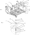
Fig. 1 represents an exploded perspective view of the battery support according to the invention, -
Fig. 2 represents a detail view A offigure 1 , corresponding to a battery clamping device according to the invention -
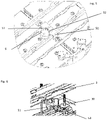
Fig. 3 represents a longitudinal sectional view of the battery clamping device according to the invention -
Fig. 4 represents a perspective view of the battery support according to the invention equipped with an anti-theft device -
Fig. 5 and Fig. 6 represents a detail view of the anti-theft device - With reference to
Figure 1 , thebattery support 1 according to the invention includes atray 10 for receiving one or more batteries. Thetray 10 is substantially horizontal. Thetray 10 comprises, for example, andanti-slip surface 11 to ensure the stability of the battery. According to the embodiment shown, thenon-slip surface 11 comprises grooves or embossments. - The
battery support 1 also comprises at least twoside walls 12 mounted on two opposite sides of thetray 10. Theside walls 12 are substantially perpendicular to thetray 10. Theside walls 12 may include means for attaching the battery support to the vehicle chassis. - The battery or batteries placed on the
tray 10 are held on thebattery support 1 by a holding device. The holding device comprises aflange 2 and at least onerod 3, afirst end 30 of which is threaded. Theflange 2 comprises ahole 21 for the passage of thefirst end 30 of therod 3. The second end of therod 3 is mounted on thetray 10 of thebattery support 1. The mounting of therod 3 on theplate 11 is for example done by screwing. Theflange 2 is held in place on the upper side of the battery or batteries by means of aclamping device rod 3. - The clamping device is shown in detail in
Figure 2 and comprises asleeve 31 and anut 32. Thesleeve 31 comprises aflange 34. During assembly, thesleeve 31 is inserted onto thefirst end 30 of therod 3 so that theflange 34 of thesleeve 31 comes to rest on theflange 2. To do this, the dimensions of thehole 21 in the flange are at least slightly larger than the diameter of thesleeve 31 and strictly smaller than the diameter of theflange 34 of thesleeve 31. Thenut 32 is then screwed onto thefirst end 30 of therod 3 until it comes into contact with thecollar 34 of thesleeve 31. According to the invention, the surface of thenut 33 in contact with theflange 34 of thesleeve 31 comprises a toothing. Similarly, the surface of thecollar 34 of thebushing 31 in contact with the nut during assembly includes a toothing. - The teeth of the
nut 32 and theflange 34 are shaped to engage each other. According to the embodiment shown, the teeth of the toothing are formed with a flank inclined with respect to the contact surface and a flank substantially perpendicular to the contact surface. Thus, at the end of tightening, of thenut 32, the engagement of the teeth of thenut 32 and thecollar 34 during assembly reduces the risk of loosening due to vibrations of thebattery support 1. According to one variant, the angle of the inclined surface of the teeth of the teeth is strictly greater than the angle of the thread of the threadedrod 30. - According to the illustrated embodiment, the contact surface of the
collar 34 of thesleeve 31 with theflange 2 also comprises a toothing. This toothing prevents thebushing 31 from sliding on the contact surface of theflange 2 and thus limits overtightening of thenut 32 on theflange 2. In addition, the hole of thebushing 31 may include agroove 38 shaped to slide ongrooves 37 formed on therod 30. Thegrooves 37 are formed on a portion of theshaft 30 beyond thethread 35. When thebushing 31 is mounted on therod 30, thespline 38 of thebushing 31 is engaged in the grooves of therod 30 which prevents rotation of thebushing 31 relative to therod 30. Therod 30 may also include ashoulder 36 intended to form a stop for thebushing 31 when thebushing 31 is mounted on therod 30. - More specifically,
Figure 3 shows the relative position of theflange 2, therod 30, thenut 31, and thebushing 31 when theflange 2 is mounted on abattery 4 that is placed on the battery support. When thebattery 4 is mounted on the rack, theflange 2 is mounted on at least onerod 30 through the hole in theflange 2. Thebushing 31 is then mounted on therod 30. The spline of thebushing 31 slides over the grooves of therod 30. When present, theshoulder 36 holds thebushing 31 onto the threadedrod 30. - The
nut 32 is then screwed onto thethread 35 of therod 30 until it comes into contact with the teeth of theflange 34 of thesleeve 31. The engagement of the teeth of thenut 32 with the teeth of thesleeve 31 forms a mechanical stop ensuring optimal tightening of theflange 2 on the battery and reducing the risk of loosening of thenut 32. - According to the embodiment shown in
Figures 4 ,5 and 6 , the battery support according to the invention also comprises ananti-theft device flanges 2 holding the battery orbatteries 4 on thetray 10 of the battery support. - The anti-theft device comprises, for example, a
bar 50 ensuring the connection between at least twoflanges 2. Thebar 50 of the anti-theft device is, for example, fixed to theflanges 2 via thenuts 32 of the clamping device. Thebar 50 can also be fixed by other means which prevent it from being dismantled with conventional tools. Thus, thenuts 32 of the device can be replaced by nuts having a specific shape incompatible with usual tools and requiring a specific tool for disassembly. - In order to prevent the removal of the
bar 50, thebar 50 includes aslot 52 allowing the passage of an arch (or loop) of arod 51. When a lock 6 (e.g., a padlock) is attached in therod 51 it is no longer possible to remove thebar 50 from the anti-theft device. Therod 51 has two ends 53 each of which is mounted on a threadedrod 30 of thebattery support 1. For this purpose, each end of therod 51 may comprise a ring into which the threadedrod 30 is slid. - When mounting the anti-theft device, the
rod 51 is mounted on two adjacent threadedrods 30 before the nuts 32 are placed on the threadedrods 30. Theflanges 2 are then inserted onto the threadedrods 30. Thebar 50 is then placed on the two adjacent threadedrods 30 to connect twoadjacent flanges 2. The arch of therod 51 is inserted into theslot 52 of thebar 50. Thesleeves 31 of the locking device are then mounted on the threadedrods 30 so that thebar 50 is gripped between theflange 2 and asleeve 31. The nuts 32 are then screwed onto the threadedrods 30. Thelock 6 can then be attached to therod arch 51. - It is to be understood that the present invention is not limited to the embodiments described above and illustrated in the drawings; rather, the skilled person will recognize that many changes and modifications may be made within the scope of the appended claims.
Claims (13)
- A Battery support (1) for a motor vehicle comprising a tray (10) for receiving at least one battery (4), a device for holding the battery or batteries on the tray, the holding device comprising a flange (2) on a threaded rod (30) and a device (31, 32) for clamping the flange (2) on the battery or batteries, characterized in that the clamping device comprises:- a sleeve (31) slidably mounted on the threaded rod (30) and comprising a collar (34) bearing on the flange,- a nut (32) mounted on the threaded rod and bearing on the collar of the sleeve- the contact surfaces between the nut (32) and the collar (34) of the bushing comprises serrations.
- The battery support (1) for a motor vehicle according to claim 1, characterized in that the contact surface between the flange (34) and the flange (2) comprises serrations.
- The battery support (1) for a motor vehicle according to claim 2, characterized in that the teeth of the toothing are formed by a flap inclined with respect to the contact surface and a flap substantially perpendicular to the contact surface.
- The battery support (1) for a motor vehicle according to claim 3, characterized in that the angle of the inclined plane of the gear teeth is strictly greater than the angle of the thread of the threaded rod (30).
- The battery support (1) for motor vehicle according to one of the preceding claims, characterized in that the threaded rod (30) is mounted substantially perpendicular to the plate (10).
- The battery support (1) for a motor vehicle according to one of the preceding claims, characterized in that the flange (2) is substantially parallel to the plate (10).
- The battery support (1) for a motor vehicle according to one of the preceding claims, characterized in that the threaded rod (30) comprises a stop (36) for sliding the sleeve (31).
- The battery support (1) for a motor vehicle according to any of the preceding claims, characterized in that the tray (10) comprises side walls (12).
- The battery support (1) for a motor vehicle according to any of the preceding claims characterized in that the cross-section of the flange (2) is U-shaped.
- The battery support (1) for a motor vehicle according to one of the preceding claims, characterized in that it comprises two flanges (2) and an anti-theft device ensuring the connection and locking of the two flanges to at least two threaded rods (30).
- The battery support (1) for a motor vehicle according to the preceding claim, characterized in that the anti-theft device comprises:- a bar (50), each end of the bar being mounted on a flange (2) via the clamping device so that the collar of the sleeve (31) comes to rest on the bar (50).
- The battery support (1) for a motor vehicle according to the preceding claim, characterized in that the anti-theft device comprises:- a rod (51), each end (53) of which being mounted on the threaded rods (30)- the rod (51) comprising a portion forming an arch- the bar comprising a slot (52) arranged to receive the arch-shaped portion of the rod.
- A motor vehicle including a battery support according to any of the preceding claims.
Priority Applications (3)
| Application Number | Priority Date | Filing Date | Title |
|---|---|---|---|
| EP21194163.8A EP4140790B1 (en) | 2021-08-31 | 2021-08-31 | Motor vehicle battery support |
| US17/894,340 US12272835B2 (en) | 2021-08-31 | 2022-08-24 | Motor vehicle battery support |
| CN202211049558.XA CN115732838A (en) | 2021-08-31 | 2022-08-30 | Battery support for motor vehicles |
Applications Claiming Priority (1)
| Application Number | Priority Date | Filing Date | Title |
|---|---|---|---|
| EP21194163.8A EP4140790B1 (en) | 2021-08-31 | 2021-08-31 | Motor vehicle battery support |
Publications (3)
| Publication Number | Publication Date |
|---|---|
| EP4140790A1 true EP4140790A1 (en) | 2023-03-01 |
| EP4140790C0 EP4140790C0 (en) | 2024-10-09 |
| EP4140790B1 EP4140790B1 (en) | 2024-10-09 |
Family
ID=77910526
Family Applications (1)
| Application Number | Title | Priority Date | Filing Date |
|---|---|---|---|
| EP21194163.8A Active EP4140790B1 (en) | 2021-08-31 | 2021-08-31 | Motor vehicle battery support |
Country Status (3)
| Country | Link |
|---|---|
| US (1) | US12272835B2 (en) |
| EP (1) | EP4140790B1 (en) |
| CN (1) | CN115732838A (en) |
Families Citing this family (3)
| Publication number | Priority date | Publication date | Assignee | Title |
|---|---|---|---|---|
| JP7322914B2 (en) * | 2021-03-24 | 2023-08-08 | いすゞ自動車株式会社 | In-vehicle equipment mounting device |
| CN115958629B (en) * | 2021-10-11 | 2025-03-28 | 富泰京精密电子(烟台)有限公司 | Battery fixture and mobile robot |
| WO2025012656A1 (en) * | 2023-07-11 | 2025-01-16 | Locks4Vans Ltd | Vehicle battery security |
Citations (3)
| Publication number | Priority date | Publication date | Assignee | Title |
|---|---|---|---|---|
| US3498400A (en) * | 1967-11-24 | 1970-03-03 | Herbert Hysmith | Battery locking means |
| US4535863A (en) * | 1983-08-26 | 1985-08-20 | Becker John R | Battery security and hold-down device |
| US20150089981A1 (en) | 2013-09-27 | 2015-04-02 | Cecil W. Renfro | Commercial motor vehicle and heavy equipment battery locking device and system for use |
Family Cites Families (36)
| Publication number | Priority date | Publication date | Assignee | Title |
|---|---|---|---|---|
| US1208236A (en) * | 1916-01-19 | 1916-12-12 | Frank H Thompson | Lock for coupling-nuts. |
| US1577292A (en) * | 1925-01-15 | 1926-03-16 | Claude P Obreiter | Storage-battery theftproof locking device |
| US2791898A (en) * | 1955-07-29 | 1957-05-14 | James R Pegg | Battery lock |
| US2833363A (en) * | 1955-10-07 | 1958-05-06 | Gen Motors Corp | Retainer means for batteries and the like |
| US2849074A (en) * | 1956-07-12 | 1958-08-26 | Gen Motors Corp | Battery retainer means |
| US3826115A (en) * | 1972-09-12 | 1974-07-30 | B Davis | Battery locking device |
| US4038843A (en) * | 1976-08-16 | 1977-08-02 | Daley Jr Richard John | Security devices for mounting CB radio, tape player, stereo or the like in motor vehicles |
| US4129194A (en) * | 1977-07-28 | 1978-12-12 | Eaton Corporation | Hold-down device for storage batteries |
| US4191034A (en) * | 1977-10-31 | 1980-03-04 | Jacob Froess | Battery lock |
| US4249403A (en) * | 1979-07-25 | 1981-02-10 | Calvin Littlejohn | Battery locking means |
| US4520887A (en) * | 1983-02-04 | 1985-06-04 | D & S Plug Corporation | Battery holddown arrangement |
| JPS60156053U (en) * | 1984-03-28 | 1985-10-17 | 日産自動車株式会社 | Automobile battery mounting structure |
| US4926953A (en) * | 1984-12-24 | 1990-05-22 | Platt Richard B | Battery hold-down structure |
| US5052198A (en) * | 1990-07-30 | 1991-10-01 | Elektrek Partnership | Battery lock and hold-down device |
| US5409338A (en) * | 1993-05-04 | 1995-04-25 | Hong Kong Disc Lock Company, Limited | Wedge-action lock washer assembly having coupled washers |
| US5377947A (en) * | 1993-08-23 | 1995-01-03 | Johnson; Jerome | Battery holddown |
| JP2922792B2 (en) * | 1994-09-09 | 1999-07-26 | 株式会社クボタ | Electric cart battery support structure |
| CN2559823Y (en) * | 2002-07-31 | 2003-07-09 | 朴明基 | Anti-loosing self-locking washer |
| JP3754016B2 (en) * | 2002-10-16 | 2006-03-08 | 川崎重工業株式会社 | Vehicle battery mounting structure |
| FR2894388B1 (en) * | 2005-12-02 | 2016-01-22 | Renault Sas | ELECTRICITY GENERATION MODULE COMPRISING A PLURALITY OF ELECTROCHEMICAL CELLS |
| AU2008200632B2 (en) * | 2007-02-09 | 2011-06-30 | Kangas, Eila Anneli | Locking washer |
| KR20100048444A (en) * | 2008-10-31 | 2010-05-11 | 현대자동차주식회사 | Cam washer with saw tooth and structure for connecting timing chain cover to cylinder block using same in vehicle |
| FR2961869B1 (en) * | 2010-06-25 | 2012-08-03 | Ct Tech Des Ind Mecaniques | DOUBLE EFFECT LOCK WASHER |
| FR2968370B1 (en) * | 2010-12-06 | 2013-09-06 | Airbus Operations Sas | NUT COMPRISING AN ANTI-ROTATION SYSTEM AND FIXING DEVICE EQUIPPED WITH SAID NUT |
| CN102705344B (en) * | 2012-05-23 | 2014-06-25 | 上海萨美锐工业机械有限公司 | Combined lock washer |
| KR102076971B1 (en) * | 2012-11-27 | 2020-04-07 | 에스케이이노베이션 주식회사 | Connection Apparatus for Power Source and Battery Pack having the Same |
| CN103560340A (en) * | 2013-10-29 | 2014-02-05 | 江苏士林电气设备有限公司 | Anti-loosening wind power bus connecting component |
| CN103531922A (en) * | 2013-10-29 | 2014-01-22 | 江苏士林电气设备有限公司 | A wind power bus connection component |
| CN104454912A (en) * | 2014-12-16 | 2015-03-25 | 武汉武船机电设备有限责任公司 | Vibration resistant anti-loose washer and screw thread pair |
| DE102015204724A1 (en) * | 2015-03-16 | 2016-09-22 | Volkswagen Aktiengesellschaft | Means of transport and arrangement for connecting an electrochemical energy store to a vehicle electrical system of an electrically driven means of transportation |
| JP2017013557A (en) * | 2015-06-29 | 2017-01-19 | スズキ株式会社 | Battery tray structure |
| DE102016015024A1 (en) * | 2016-12-16 | 2017-07-06 | Daimler Ag | Tolerance-compensating detachable connection of highly loaded components |
| CN106763092A (en) * | 2017-03-11 | 2017-05-31 | 王金娣 | A kind of stop nut |
| KR20180131038A (en) | 2017-05-31 | 2018-12-10 | 천병환 | Fastening structure of prevent bolt loosing with lock washer |
| DE102017215086A1 (en) * | 2017-08-29 | 2019-02-28 | Volkswagen Aktiengesellschaft | Device for fastening at least one battery module to a housing bottom of a battery housing |
| AT521809A1 (en) * | 2018-11-22 | 2020-05-15 | Avl List Gmbh | Isolation and fastening device for a fuel cell system |
-
2021
- 2021-08-31 EP EP21194163.8A patent/EP4140790B1/en active Active
-
2022
- 2022-08-24 US US17/894,340 patent/US12272835B2/en active Active
- 2022-08-30 CN CN202211049558.XA patent/CN115732838A/en active Pending
Patent Citations (3)
| Publication number | Priority date | Publication date | Assignee | Title |
|---|---|---|---|---|
| US3498400A (en) * | 1967-11-24 | 1970-03-03 | Herbert Hysmith | Battery locking means |
| US4535863A (en) * | 1983-08-26 | 1985-08-20 | Becker John R | Battery security and hold-down device |
| US20150089981A1 (en) | 2013-09-27 | 2015-04-02 | Cecil W. Renfro | Commercial motor vehicle and heavy equipment battery locking device and system for use |
Also Published As
| Publication number | Publication date |
|---|---|
| US20230068558A1 (en) | 2023-03-02 |
| US12272835B2 (en) | 2025-04-08 |
| EP4140790C0 (en) | 2024-10-09 |
| EP4140790B1 (en) | 2024-10-09 |
| CN115732838A (en) | 2023-03-03 |
Similar Documents
| Publication | Publication Date | Title |
|---|---|---|
| US12272835B2 (en) | Motor vehicle battery support | |
| US3241408A (en) | Vehicle wheel nut or bolt | |
| US5716154A (en) | Attachment device | |
| US4284114A (en) | Locking member for a clamping bolt | |
| EP3571081B1 (en) | A suspension device | |
| CN110576801B (en) | Expansion module for load carrier | |
| CA2063268A1 (en) | Lock and hexagonal nut combination for mounting vehicle wheels | |
| US6908254B2 (en) | Cam nut adjustment apparatus and method | |
| WO2000023288A1 (en) | A fastener device | |
| WO2010037547A1 (en) | Wheel nut locks | |
| EP1498616B1 (en) | Securing spaced elements to one another | |
| US6454486B2 (en) | Device for the detachable fastening of a steering wheel on a steering shaft | |
| JP7620729B2 (en) | Mounting structure for a hook shock absorber that can be pushed up with small tightening torque in a compact space | |
| JP3572491B2 (en) | Nuts and tools for fastening them | |
| JPH01269784A (en) | Pipe holder and method of using thereof | |
| KR100325752B1 (en) | a mounting apparatus for battery of vehicles | |
| GB2327401A (en) | Mudflaps for vehicles | |
| JP2009034733A (en) | Bolt-nut corotation prevention tool | |
| JPH0662466U (en) | Terminal mounting structure | |
| KR0137398Y1 (en) | Steering wheel clearance adjustment tool | |
| JPH0347826Y2 (en) | ||
| KR0112542Y1 (en) | Fastening arrangement of aluminium-wheel-nut for a car | |
| US4371212A (en) | Wheel rim bolt attachment | |
| KR0122209Y1 (en) | Combined structure of automobile stabilizer shaft | |
| JP2588089B2 (en) | Automotive repair aids |
Legal Events
| Date | Code | Title | Description |
|---|---|---|---|
| PUAI | Public reference made under article 153(3) epc to a published international application that has entered the european phase |
Free format text: ORIGINAL CODE: 0009012 |
|
| STAA | Information on the status of an ep patent application or granted ep patent |
Free format text: STATUS: THE APPLICATION HAS BEEN PUBLISHED |
|
| AK | Designated contracting states |
Kind code of ref document: A1 Designated state(s): AL AT BE BG CH CY CZ DE DK EE ES FI FR GB GR HR HU IE IS IT LI LT LU LV MC MK MT NL NO PL PT RO RS SE SI SK SM TR |
|
| STAA | Information on the status of an ep patent application or granted ep patent |
Free format text: STATUS: REQUEST FOR EXAMINATION WAS MADE |
|
| 17P | Request for examination filed |
Effective date: 20230830 |
|
| RBV | Designated contracting states (corrected) |
Designated state(s): AL AT BE BG CH CY CZ DE DK EE ES FI FR GB GR HR HU IE IS IT LI LT LU LV MC MK MT NL NO PL PT RO RS SE SI SK SM TR |
|
| GRAP | Despatch of communication of intention to grant a patent |
Free format text: ORIGINAL CODE: EPIDOSNIGR1 |
|
| STAA | Information on the status of an ep patent application or granted ep patent |
Free format text: STATUS: GRANT OF PATENT IS INTENDED |
|
| RIC1 | Information provided on ipc code assigned before grant |
Ipc: H01M 50/264 20210101ALN20231218BHEP Ipc: H01M 50/249 20210101ALN20231218BHEP Ipc: H01M 50/20 20210101ALN20231218BHEP Ipc: B60R 16/04 20060101ALI20231218BHEP Ipc: B60K 1/04 20190101AFI20231218BHEP |
|
| INTG | Intention to grant announced |
Effective date: 20240112 |
|
| GRAJ | Information related to disapproval of communication of intention to grant by the applicant or resumption of examination proceedings by the epo deleted |
Free format text: ORIGINAL CODE: EPIDOSDIGR1 |
|
| STAA | Information on the status of an ep patent application or granted ep patent |
Free format text: STATUS: REQUEST FOR EXAMINATION WAS MADE |
|
| INTC | Intention to grant announced (deleted) | ||
| RIC1 | Information provided on ipc code assigned before grant |
Ipc: H01M 50/264 20210101ALN20240415BHEP Ipc: H01M 50/249 20210101ALN20240415BHEP Ipc: H01M 50/20 20210101ALN20240415BHEP Ipc: B60R 16/04 20060101ALI20240415BHEP Ipc: B60K 1/04 20190101AFI20240415BHEP |
|
| GRAP | Despatch of communication of intention to grant a patent |
Free format text: ORIGINAL CODE: EPIDOSNIGR1 |
|
| STAA | Information on the status of an ep patent application or granted ep patent |
Free format text: STATUS: GRANT OF PATENT IS INTENDED |
|
| INTG | Intention to grant announced |
Effective date: 20240607 |
|
| RIC1 | Information provided on ipc code assigned before grant |
Ipc: H01M 50/264 20210101ALN20240524BHEP Ipc: H01M 50/249 20210101ALN20240524BHEP Ipc: H01M 50/20 20210101ALN20240524BHEP Ipc: B60R 16/04 20060101ALI20240524BHEP Ipc: B60K 1/04 20190101AFI20240524BHEP |
|
| GRAS | Grant fee paid |
Free format text: ORIGINAL CODE: EPIDOSNIGR3 |
|
| GRAA | (expected) grant |
Free format text: ORIGINAL CODE: 0009210 |
|
| STAA | Information on the status of an ep patent application or granted ep patent |
Free format text: STATUS: THE PATENT HAS BEEN GRANTED |
|
| AK | Designated contracting states |
Kind code of ref document: B1 Designated state(s): AL AT BE BG CH CY CZ DE DK EE ES FI FR GB GR HR HU IE IS IT LI LT LU LV MC MK MT NL NO PL PT RO RS SE SI SK SM TR |
|
| REG | Reference to a national code |
Ref country code: CH Ref legal event code: EP |
|
| REG | Reference to a national code |
Ref country code: DE Ref legal event code: R096 Ref document number: 602021019843 Country of ref document: DE |
|
| REG | Reference to a national code |
Ref country code: IE Ref legal event code: FG4D |
|
| U01 | Request for unitary effect filed |
Effective date: 20241029 |
|
| U07 | Unitary effect registered |
Designated state(s): AT BE BG DE DK EE FI FR IT LT LU LV MT NL PT RO SE SI Effective date: 20241111 |
|
| PG25 | Lapsed in a contracting state [announced via postgrant information from national office to epo] |
Ref country code: HR Free format text: LAPSE BECAUSE OF FAILURE TO SUBMIT A TRANSLATION OF THE DESCRIPTION OR TO PAY THE FEE WITHIN THE PRESCRIBED TIME-LIMIT Effective date: 20241009 Ref country code: IS Free format text: LAPSE BECAUSE OF FAILURE TO SUBMIT A TRANSLATION OF THE DESCRIPTION OR TO PAY THE FEE WITHIN THE PRESCRIBED TIME-LIMIT Effective date: 20250209 |
|
| PG25 | Lapsed in a contracting state [announced via postgrant information from national office to epo] |
Ref country code: ES Free format text: LAPSE BECAUSE OF FAILURE TO SUBMIT A TRANSLATION OF THE DESCRIPTION OR TO PAY THE FEE WITHIN THE PRESCRIBED TIME-LIMIT Effective date: 20241009 |
|
| PG25 | Lapsed in a contracting state [announced via postgrant information from national office to epo] |
Ref country code: NO Free format text: LAPSE BECAUSE OF FAILURE TO SUBMIT A TRANSLATION OF THE DESCRIPTION OR TO PAY THE FEE WITHIN THE PRESCRIBED TIME-LIMIT Effective date: 20250109 |
|
| PG25 | Lapsed in a contracting state [announced via postgrant information from national office to epo] |
Ref country code: GR Free format text: LAPSE BECAUSE OF FAILURE TO SUBMIT A TRANSLATION OF THE DESCRIPTION OR TO PAY THE FEE WITHIN THE PRESCRIBED TIME-LIMIT Effective date: 20250110 |
|
| PG25 | Lapsed in a contracting state [announced via postgrant information from national office to epo] |
Ref country code: PL Free format text: LAPSE BECAUSE OF FAILURE TO SUBMIT A TRANSLATION OF THE DESCRIPTION OR TO PAY THE FEE WITHIN THE PRESCRIBED TIME-LIMIT Effective date: 20241009 |
|
| PG25 | Lapsed in a contracting state [announced via postgrant information from national office to epo] |
Ref country code: RS Free format text: LAPSE BECAUSE OF FAILURE TO SUBMIT A TRANSLATION OF THE DESCRIPTION OR TO PAY THE FEE WITHIN THE PRESCRIBED TIME-LIMIT Effective date: 20250109 |
|
| PG25 | Lapsed in a contracting state [announced via postgrant information from national office to epo] |
Ref country code: SM Free format text: LAPSE BECAUSE OF FAILURE TO SUBMIT A TRANSLATION OF THE DESCRIPTION OR TO PAY THE FEE WITHIN THE PRESCRIBED TIME-LIMIT Effective date: 20241009 |
|
| PG25 | Lapsed in a contracting state [announced via postgrant information from national office to epo] |
Ref country code: SK Free format text: LAPSE BECAUSE OF FAILURE TO SUBMIT A TRANSLATION OF THE DESCRIPTION OR TO PAY THE FEE WITHIN THE PRESCRIBED TIME-LIMIT Effective date: 20241009 |
|
| PG25 | Lapsed in a contracting state [announced via postgrant information from national office to epo] |
Ref country code: CZ Free format text: LAPSE BECAUSE OF FAILURE TO SUBMIT A TRANSLATION OF THE DESCRIPTION OR TO PAY THE FEE WITHIN THE PRESCRIBED TIME-LIMIT Effective date: 20241009 |
|
| PLBE | No opposition filed within time limit |
Free format text: ORIGINAL CODE: 0009261 |
|
| STAA | Information on the status of an ep patent application or granted ep patent |
Free format text: STATUS: NO OPPOSITION FILED WITHIN TIME LIMIT |
|
| 26N | No opposition filed |
Effective date: 20250710 |
|
| U20 | Renewal fee for the european patent with unitary effect paid |
Year of fee payment: 5 Effective date: 20250825 |
|
| REG | Reference to a national code |
Ref country code: CH Ref legal event code: H13 Free format text: ST27 STATUS EVENT CODE: U-0-0-H10-H13 (AS PROVIDED BY THE NATIONAL OFFICE) Effective date: 20260324 |
|
| PG25 | Lapsed in a contracting state [announced via postgrant information from national office to epo] |
Ref country code: MC Free format text: LAPSE BECAUSE OF FAILURE TO SUBMIT A TRANSLATION OF THE DESCRIPTION OR TO PAY THE FEE WITHIN THE PRESCRIBED TIME-LIMIT Effective date: 20241009 |
|
| PG25 | Lapsed in a contracting state [announced via postgrant information from national office to epo] |
Ref country code: CH Free format text: LAPSE BECAUSE OF NON-PAYMENT OF DUE FEES Effective date: 20250831 |